EP3645801B1 - Expandable container shelter - Google Patents
Expandable container shelter Download PDFInfo
- Publication number
- EP3645801B1 EP3645801B1 EP18756310.1A EP18756310A EP3645801B1 EP 3645801 B1 EP3645801 B1 EP 3645801B1 EP 18756310 A EP18756310 A EP 18756310A EP 3645801 B1 EP3645801 B1 EP 3645801B1
- Authority
- EP
- European Patent Office
- Prior art keywords
- container
- shelter
- roof
- expandable
- supporting frames
- Prior art date
- Legal status (The legal status is an assumption and is not a legal conclusion. Google has not performed a legal analysis and makes no representation as to the accuracy of the status listed.)
- Active
Links
Images


Classifications
-
- E—FIXED CONSTRUCTIONS
- E04—BUILDING
- E04B—GENERAL BUILDING CONSTRUCTIONS; WALLS, e.g. PARTITIONS; ROOFS; FLOORS; CEILINGS; INSULATION OR OTHER PROTECTION OF BUILDINGS
- E04B1/00—Constructions in general; Structures which are not restricted either to walls, e.g. partitions, or floors or ceilings or roofs
- E04B1/343—Structures characterised by movable, separable, or collapsible parts, e.g. for transport
- E04B1/344—Structures characterised by movable, separable, or collapsible parts, e.g. for transport with hinged parts
- E04B1/3442—Structures characterised by movable, separable, or collapsible parts, e.g. for transport with hinged parts folding out from a core cell
- E04B1/3444—Structures characterised by movable, separable, or collapsible parts, e.g. for transport with hinged parts folding out from a core cell with only lateral unfolding
-
- E—FIXED CONSTRUCTIONS
- E04—BUILDING
- E04B—GENERAL BUILDING CONSTRUCTIONS; WALLS, e.g. PARTITIONS; ROOFS; FLOORS; CEILINGS; INSULATION OR OTHER PROTECTION OF BUILDINGS
- E04B1/00—Constructions in general; Structures which are not restricted either to walls, e.g. partitions, or floors or ceilings or roofs
- E04B1/343—Structures characterised by movable, separable, or collapsible parts, e.g. for transport
- E04B1/34336—Structures movable as a whole, e.g. mobile home structures
-
- E—FIXED CONSTRUCTIONS
- E04—BUILDING
- E04B—GENERAL BUILDING CONSTRUCTIONS; WALLS, e.g. PARTITIONS; ROOFS; FLOORS; CEILINGS; INSULATION OR OTHER PROTECTION OF BUILDINGS
- E04B7/00—Roofs; Roof construction with regard to insulation
- E04B7/02—Roofs; Roof construction with regard to insulation with plane sloping surfaces, e.g. saddle roofs
- E04B7/022—Roofs; Roof construction with regard to insulation with plane sloping surfaces, e.g. saddle roofs consisting of a plurality of parallel similar trusses or portal frames
-
- E—FIXED CONSTRUCTIONS
- E04—BUILDING
- E04H—BUILDINGS OR LIKE STRUCTURES FOR PARTICULAR PURPOSES; SWIMMING OR SPLASH BATHS OR POOLS; MASTS; FENCING; TENTS OR CANOPIES, IN GENERAL
- E04H1/00—Buildings or groups of buildings for dwelling or office purposes; General layout, e.g. modular co-ordination or staggered storeys
- E04H1/12—Small buildings or other erections for limited occupation, erected in the open air or arranged in buildings, e.g. kiosks, waiting shelters for bus stops or for filling stations, roofs for railway platforms, watchmen's huts or dressing cubicles
- E04H1/1205—Small buildings erected in the open air
-
- E—FIXED CONSTRUCTIONS
- E04—BUILDING
- E04B—GENERAL BUILDING CONSTRUCTIONS; WALLS, e.g. PARTITIONS; ROOFS; FLOORS; CEILINGS; INSULATION OR OTHER PROTECTION OF BUILDINGS
- E04B1/00—Constructions in general; Structures which are not restricted either to walls, e.g. partitions, or floors or ceilings or roofs
- E04B1/343—Structures characterised by movable, separable, or collapsible parts, e.g. for transport
- E04B1/34315—Structures characterised by movable, separable, or collapsible parts, e.g. for transport characterised by separable parts
- E04B1/34317—Set of building elements forming a self-contained package for transport before assembly
-
- E—FIXED CONSTRUCTIONS
- E04—BUILDING
- E04H—BUILDINGS OR LIKE STRUCTURES FOR PARTICULAR PURPOSES; SWIMMING OR SPLASH BATHS OR POOLS; MASTS; FENCING; TENTS OR CANOPIES, IN GENERAL
- E04H1/00—Buildings or groups of buildings for dwelling or office purposes; General layout, e.g. modular co-ordination or staggered storeys
- E04H1/12—Small buildings or other erections for limited occupation, erected in the open air or arranged in buildings, e.g. kiosks, waiting shelters for bus stops or for filling stations, roofs for railway platforms, watchmen's huts or dressing cubicles
- E04H2001/1283—Small buildings of the ISO containers type
-
- E—FIXED CONSTRUCTIONS
- E04—BUILDING
- E04H—BUILDINGS OR LIKE STRUCTURES FOR PARTICULAR PURPOSES; SWIMMING OR SPLASH BATHS OR POOLS; MASTS; FENCING; TENTS OR CANOPIES, IN GENERAL
- E04H3/00—Buildings or groups of buildings for public or similar purposes; Institutions, e.g. infirmaries or prisons
- E04H3/08—Hospitals, infirmaries, or the like; Schools; Prisons
Definitions
- the technical solution relates to expandable container shelters, particularly those which use transportation container as a container, for example made on the basis of intermodal container, also known as the ISO container, with lengths of 6 m and 12 m, 20 ft and 40 ft, respectively. More particularly, the technical solution relates to mentioned expandable container shelters, those which include parts for the construction of a shelter structure associated with this container that are connected to the container and stored in this container during its transportation and storage.
- Extendable or expandable containers are standard product, mainly used for field applications as mobile hospital buildings, but also as accommodation, administrative or service units.
- lateral extension is approximately equal to the width of the container and as the container is usually extended to both sides, resulting object, including the container, is thereby substantially three times as wide as the container itself.
- one or both of the longitudinal walls of the container are usually lowered, where the lowered wall at the same time serves as a floor for the shelter extension of the container.
- Such shelter is then formed by a cover, supported by a metal or inflatable structure.
- the lateral extension is approximately equal to the height of the container, and as the container is usually such expanded along both longitudinal sides, resulting shelter/building has thereby the width of the container substantially increased by double the height of the container.
- Expandable container shelter having inflatable structure of the shelter is disclosed for example in WO2017/048777 A1 .
- WO2014/082104 A1 discloses a structure which includes a container which forms a housing and, mounted to the housing a plurality of walls which are pivotally interconnected and which are movable between a compact stored configuration and an extended operative configuration. These walls are being extended from longitudinal sides of the container by means of vertical hinging supports at the ends of the longitudinal sides of the container and vertical pivotal supports with which the walls are mutually connected.
- This solution allows for enclosing larger area, however, if this area is to be covered, said walls cannot be used as supporting for attaching a roof supports.
- Roof support in this case a canvas, is provided in this solution in the form of a mast embedded in the ground and centrally positioned within the enclosure formed by the walls. Then, the canvas is stretched from the mast, and attached to the walls.
- Document DE 26 20 689 B1 discloses transportable building, which has floor, side walls and roof.
- the room cell enclosing walls, ceiling and floor elements are hinged to a central stiffened support core. These hinged elements can be folded against the support core for transporting purposes.
- the hinged elements incorporate also fittings and service cables and pipes. This arrangement of hinged elements allows for creating a building widened from central part on both sides for no more than is the height of the building.
- the central stiffened support core is an original structure to be built with each building, which does not make use of or profit from existing standardized transportation container.
- Document WO 98/10954 A1 discloses arrangement of an expandable, mobile accommodation of activities comprising a central structure having along at least one of its longitudinal sides a longitudinal side wall that is movable in parallel motion outwards together with folding floor and roof sections.
- Front and rear side walls are arranged to be swung out and connected to other parts.
- the front and rear side walls are arranged to initially be swung out and at the top portions and bottom portions of the inner sides provided with guide means for the movement of the longitudinal side wall.
- the guide means consist of rails attached to the front and rear side walls and provided with rack rail surfaces, which mesh with driven pinions attached to the end edges of the longitudinal side wall.
- the central structure does not make use of or profit from existing standardized transportation container, rather it is individual mobile platform. Further this expandable mobile structure utilizes the arrangement of mutually connected wall, foldable roof and floor sections to be extended by use of power driving means, which makes the structure rather complex.
- Document WO 2007/067153 A2 discloses a mobile multi-purpose unit in a cuboid form.
- Said unit consists of a lower part, two fixed front walls optionally a top, and mobile bottom parts, optionally a mechanism for the unfolding thereof, and optionally supporting strips.
- the mobile unit can also be formed from wall parts. It can also be formed from lateral parts, optionally from roof carriers and optionally from roof parts. Once unfolded, the mobile bottom parts form a bottom with the central bottom part, the surface of said bottom being no larger than seven times the cuboid surface. All of said parts, optionally the mechanism for the unfolding thereof, optionally the supporting strips, optionally the roof carrier, and optionally the roof parts, are incorporated into the cuboid.
- This mobile unit utilizes the arrangement of mutually connected foldable side walls, foldable floor plates, and separate roof parts that are designed to be able to provide support for another such mobile unit to be built atop.
- the unit does not make use of or profit from existing standardized transportation container, rather it is specifically built structure.
- Object of this solution is to provide improved expandable container shelter, entirely transportable and storable in a single transportation container, which is able to provide maximum possible covered area when the container is expanded to its working configuration, without a need for adding external elements not comprised within this container.
- Proposed solution maximizes applicability of expandable container shelters.
- expandable container shelter according to appended claim 1, particularly such that uses transportation container as a container, for example made on the basis of intermodal container, also known as the ISO container, with lengths of 6 m and 12 m, 20 ft and 40 ft, respectively, where this container comprises elements pivotally connected to the container in vertical mounts at the ends of longitudinal side of the container, provided for creating a structure designed for extending the inner space of the container to a shelter connected with this container at the longitudinal side of the container.
- Expandable container shelter according to this technical solution is characterized in that elements provided for creating the structure designed for extending the inner space of the container to the shelter connected with this container are at least on one longitudinal side of the container composed of one pair of supporting frames.
- the supporting frame comprises at least one horizontal beam and has length in the range up to dimension equal to inner length of the container.
- the shelter roof supports which are inflatable beams, are then connected to said supporting frames.
- a connection of the roof supports to the supporting frame is of course understood also the connection of these supports to the supporting frame through other elements which can be present on this frame and can form a part of said supporting frame, such as various auxiliary beams, slats, shaped mounts, profile anchors and similar.
- the supporting frame is at least at one point of its length from its pivotal mount in the container provided by a member for securing its horizontal position.
- an auxiliary frame for providing transversal connection of the supporting frames in their opened position is mounted on the supporting frame in the area of its end opposite to its pivotal mount in the container. Then the shelter roof supports can be oriented in direction transversal to the length of the container, whereby they are connected to the auxiliary frame and the container. The auxiliary frame in its folded position can be inserted in the supporting frame in order to save space.
- Supporting frames can be placed inside the container in one plane, whereby applies that maximal sum of lengths of the supporting frames is equal to the value of the inner length of the container; in other words maximal value of the sum of lengths of the supporting frames is equal to the value of the inner length of the container.
- the supporting frames can be placed inside the container in different planes, whereby maximal length of single supporting frame can be equal up to the value of the inner length of the container.
- the inflatable beams are permanently connected to at least one supporting frame or to the container.
- the supporting frame, the auxiliary frame, roof supports and roof are in transport or storage configuration of the container placed in the inner space of the container such that they do not project out over the outline of the container.
- FIG.1 to Fig. 14 Further described examples of embodiments of expandable container shelters according to this technical solution refer to Fig.1 to Fig. 14 .
- Said figures show shelters 2, or their parts on one side of a container 1, however, these figures, at the same time, illustrate also examples of embodiments with the shelters 2 at both sides of the container 1 because building of the shelter 2 at the other side of the container 1 is in fact analogous.
- the invention concerns only arrangements whereby the shelter roof supports are inflatable beams, other disclosures are provided for information only.
- embodiment of the expandable container shelter which is the most preferred in regard of maximal area covered and handling, comprises the container 1 , two pairs of horizontally swivelling supporting frames 3 comprising auxiliary swivelling frames 4 and two roofs 6, attached on inflatable beams 5, where one pair of swivelling supporting frames 3 together with one roof 6 attached on the inflatable beams 5 is placed at one long side of the container 1, and the other pair of the swivelling frames 3 together with the other roof 6 attached on the inflatable beams 5 is placed at the opposite long side of the container 1.
- symmetrical, sufficiently rigid structure composed of the container 1 and two shelters 2 placed by long sides of said container 1 is created.
- opened supporting frames 3 is mutually parallel and perpendicular to the container 1.
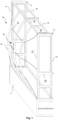
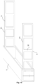
- FIG. 1 The first example of embodiment of the expanded container shelter according to this technical solution described hereinafter, is shown in Fig. 1 and Fig. 2 .
- Pair of supporting frames 3 is mounted in vertical pivotal mounts on the opposite ends of the container 1 on each longitudinal side of the container 1 .
- each one of the supporting frames 3 is with its one end mounted in one pivotal mount.
- Each supporting frame 3 comprises a pair of horizontal beams 31 with vertical reinforcements 32 and auxiliary frames 4 at free ends of the supporting frames 3.
- These auxiliary frames 4 have in this example similar structure as supporting frames 3, thus comprise a pair of horizontal beams 41 with vertical reinforcements 42. This particular arrangement of supporting frames 3 and auxiliary frames 4 is shown in Fig. 9 .
- the supporting frames 3 are placed inside the container 1 in different planes and thus maximal length of one supporting frame 3 can practically be equal to dimension of the inner length of the container 1.
- the auxiliary frame 4 of the supporting frame 3 is in this example provided such that it does not project out over the thickness of the supporting frame 3. This is advantageous in regard of space saving when the supporting frame 3 is folded.
- the auxiliary frame 4 is in this example pivotally mounted in the supporting frame 3 by its one edge. Length of the auxiliary frame 4 is in this example equal to half of the distance between the supporting frames 3 in opened working position, i.e. when unfolded supporting frames 3 are parallel.
- supporting frames 3 are one after the other opened.
- the auxiliary frames 4 are unfolded from these frames 3. It is preferred to secure opened supporting frames 3, and if appropriate, also the auxiliary frames 4 in their pivotal mounts. It is possible the structure such created further preferably stabilize by connecting the ends of the auxiliary frames 4 with members 7 for securing of horizontal position of the supporting frames 3 and/or the auxiliary frames 4, which can be commonly used, preferably height-adjustable, supports, legs, baseplates, and similar, or also wheels, runners and similar, which can help even during the step of unfolding of the frames 3 , 4.
- This structure if necessary, can be further strengthened also using corner reinforcements 9 which can stabilize the frames 3 , 4 against each other, or the supporting frames 3 against the container 1 , or diagonal reinforcements 33 , 43 which reinforce the frames 3 , 4 individually. Said steps are schematically shown in Fig. 6 , 7 and 8 . Sides of the frames 3 , 4 can be preferably in advance covered by solid or flexible material, thereby preparing walls of future object and saving time for installation.
- the roof 6 comprises, in this example, beam 5 which are at one end connected to the container 1 and at the other end to the auxiliary frames 4, as shown in Fig. 1 , or the beams 5 are connected to opposite supporting frames 3, as shown in Fig. 2 .
- roof 6 supports 5 are arcuate inflatable beams.
- the roof 6 is conventionally of canvas type, made of flexible material, or combination of flexible and not flexible material, preferably impregnated or coated fabric.
- the arcuate inflatable beam 5 is easily transportable, folded or rolled, together with the shelter 2 roof 6.
- the beam 5 can be permanently connected with material of the roof 6.
- Folded or rolled roof 6 including deflated beams 5 can be stored in the container 1 separately.
- the roof 6 Preferably it is however possible to connect at least one side of the roof 6 together with one side of the roof beams 5 permanently to the container 1, in the case the beams 5 are arranged in direction transversal to the length of the container 1; or the beams 5 can be permanently connected to at least one supporting frame 3 in the case when the beams 5 are arranged in direction accordant to the length of the container 1.
- deflated beams 5 are contained inside the container 1.
- One side of deflated beams 5 is then preferably suspended under a ceiling of the container 1 in holders, for example in guiding grooves, to be possible for the ends of the beams to be easily moved to the edge of the container 1 , i.e. to working position, when the shelter 2 roof 6 is being assembled.
- Remaining part of the beams 5 and the roofs 6 is then hanging folded under the ceiling of the container 1 , or this part of the beams 5 and roofs 6 is lying folded at the bottom of the container 1 and only a part of said beams 5 and roofs 6 corresponding approximately to the height of the container is hanging. It is preferred to suspend the roofs 6 completely, because a space is then left at the bottom of the container 1 for storing of other possible parts of the shelters 2, for example floor, or if necessary auxiliary inflatable tent, as well as technical equipment such as air conditioning unit, power generators or air compressor that can be used also for inflating the beams 5. Said arrangement is not shown in figures, as it is sufficiently clearly described and conceivable.
- the roofs 6 such placed and accessories are during transportation thus practically situated in central part of the container 1 and closed by pair of supporting frames 3 from both sides. It is preferred, in order to maintain standard dimensions of the container 1, especially in the case of ISO container, when outer side of the outer supporting frame 3 does not project out over the outline of the container 1.
- roof 6 with beams 5 is unfolded, free end of the beams 5 is attached, with known anchoring members, to the opposite side of the structure, i.e. to the auxiliary frames 4, or to the opposite supporting frame 3.
- the roof 6 is attached on the periphery with commonly available attaching means used for canvas type roofs, usually to the edges of the shelter 2 structure, which are in this case the container 1, supporting frames 3 and auxiliary frames 4.
- attaching of roof 6 periphery vary upon requirements for waterproofing, air-proofing, time of installation and other conditions, while their embodiment, if it is over the entire periphery, does not influence functionality of the assembly itself.
- a floor is also a part of the container 1, preferably coiled on a roll inside the container 1 , it is unrolled as the first to protect the roof 6 against dirtying of its inner side. Afterwards, the roof 6 is unfolded on the floor and further work continues as described in preceding paragraph.
- Roof beams 5 are then inflated, thereby stretching the roof and strengthening the entire structure of the shelter 2.
- Inflating the beams 5 is carried out in known ways form known sources of compressed air, for example by means of standardized compressor hoses and connectors from a compressor or air cylinder, if appropriate by means of electric blower and similar.
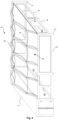
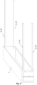
- FIG. 3 and Fig. 4 Another example of embodiment of expandable container shelter according to this technical solution described hereinafter is shown in Fig. 3 and Fig. 4 .
- the bottom structure of the shelter 2 composed basically of the container 1, supporting frames 3 and auxiliary frames 4, is substantially identical with that as described above in the example of embodiment according to Fig. 1 and Fig. 2 .
- the support 5 is provided as solid beam.
- Various knows forms of arcuate, bent or straight beams, made of metal, composite, wood, or other suitable material can be used as the solid beam 5.
- the beams 5 are attached to the bottom structure of the shelter 2 and the roof 6 is stretched upon their surface, or in suspended configuration, the roof 6 is pulled to the beam 5, or the beams 5 are installed from the underside as the last ones and the entire roof 6 is stretched by pushing the beams 5 into their given position on the bottom structure of the shelter 2.
- the roof 6 can be installed between the beams 5 by means of Keder slid into a luff groove provided in the beams 5.
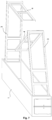
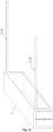
- FIG. 5 Another example of embodiment of expandable container shelter according to this technical solution described hereinafter is shown in Fig. 5
- straight beams 5 are used whose upper edge has approximately the same length as is the roof 6 span, that is in this example the distance between the supporting frames 3.
- the roof 6 is permanently attached to the beams 5 and is stored inside the container in folded or so called accordion shape. In such case, installation would be most preferably carried out by unfolding the roof 6 by means of a guiding rail or groove in the supporting frames 3 guiding the ends of straight beams 5.
- the supporting frames 3 can be shaped as shown in Fig. 12 . It is preferred then, in order to increase rigidity of such structure to provide the supporting frames 3 at their end with members 7 for securing their horizontal position, e.g. in the form of legs.
- the roof supports 5 can be arranged parallel to the supporting frame 3. Then, the roof 6 would unfold by means of guiding rail or groove on the container 1 and the auxiliary frame 4.
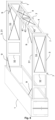
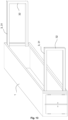
- Example of embodiment of expandable container shelter according to this technical solution where the supporting frames 3 are placed in closed configuration inside the container 1 in one plane and maximal value of the sum of lengths of the supporting frames 3 is equal to the value of the inner length of the container 1, is shown in Fig. 13 and Fig. 14 .
- length of the supporting frame 3 is equal to the half of the inner length of the container 1.
- the supporting frames 3 can be provided as extendable. It means that sliding extension part 8 is slid in the supporting frame 3, which, after the supporting frame 3 is opened, slides out and extends the supporting frame 3 by the length of this extension part 8 .
- This particular embodiment is shown in Fig. 14 .
Landscapes
- Engineering & Computer Science (AREA)
- Architecture (AREA)
- Civil Engineering (AREA)
- Structural Engineering (AREA)
- Physics & Mathematics (AREA)
- Electromagnetism (AREA)
- Health & Medical Sciences (AREA)
- Public Health (AREA)
- Tents Or Canopies (AREA)
- Buildings Adapted To Withstand Abnormal External Influences (AREA)
- Roof Covering Using Slabs Or Stiff Sheets (AREA)
Applications Claiming Priority (2)
| Application Number | Priority Date | Filing Date | Title |
|---|---|---|---|
| SK50059-2017U SK8396Y1 (sk) | 2017-06-27 | 2017-06-27 | Kontajnerový rozkladací prístrešok |
| PCT/SK2018/050009 WO2019004948A2 (en) | 2017-06-27 | 2018-06-26 | SHELTER OF EXTENSIBLE CONTAINER |
Publications (3)
| Publication Number | Publication Date |
|---|---|
| EP3645801A2 EP3645801A2 (en) | 2020-05-06 |
| EP3645801C0 EP3645801C0 (en) | 2024-09-04 |
| EP3645801B1 true EP3645801B1 (en) | 2024-09-04 |
Family
ID=63639673
Family Applications (1)
| Application Number | Title | Priority Date | Filing Date |
|---|---|---|---|
| EP18756310.1A Active EP3645801B1 (en) | 2017-06-27 | 2018-06-26 | Expandable container shelter |
Country Status (10)
| Country | Link |
|---|---|
| US (1) | US11473292B2 (pl) |
| EP (1) | EP3645801B1 (pl) |
| AU (1) | AU2018291609B2 (pl) |
| CA (1) | CA3067739A1 (pl) |
| EA (1) | EA202090035A1 (pl) |
| ES (1) | ES2996738T3 (pl) |
| PL (1) | PL3645801T3 (pl) |
| SK (1) | SK8396Y1 (pl) |
| WO (1) | WO2019004948A2 (pl) |
| ZA (1) | ZA202000080B (pl) |
Families Citing this family (10)
| Publication number | Priority date | Publication date | Assignee | Title |
|---|---|---|---|---|
| WO2021062515A1 (en) * | 2019-10-01 | 2021-04-08 | Concepts To Solutions Inc. | Portable containment structure having inflated sealed interior space |
| GB2591096B (en) * | 2020-01-14 | 2024-09-04 | Dawsongroup Plc | An inflatable structure and method of transporting an inflatable structure |
| US20220025664A1 (en) * | 2020-07-23 | 2022-01-27 | Lifebox | Portable enclosed-structure deployment system |
| US20240141639A1 (en) * | 2021-03-03 | 2024-05-02 | Rohe Homes Ltd. | Systems and methods for manufacturing anddeploying modular buildings |
| US20220396947A1 (en) * | 2021-03-30 | 2022-12-15 | John D. Moore | Compactible and foldable Drop shop building |
| US20220372779A1 (en) * | 2021-05-05 | 2022-11-24 | Deployed Resources, LLC | Expandable expeditionary container system |
| US12378761B2 (en) | 2021-10-15 | 2025-08-05 | Gti Ip Corp. | Expandable portable shelter and structures of multiple expandable portable shelters |
| US20240125109A1 (en) * | 2022-10-12 | 2024-04-18 | A&C Future, Inc. | Movable home with retractable structures |
| US20250305315A1 (en) * | 2023-05-12 | 2025-10-02 | Cuby Technologies, Inc. | Intermodal-container-based factory |
| US20250084633A1 (en) * | 2023-09-08 | 2025-03-13 | A&C Future, Inc. | Expandable housing structure with stacking walls |
Family Cites Families (29)
| Publication number | Priority date | Publication date | Assignee | Title |
|---|---|---|---|---|
| DE2620689C2 (de) * | 1976-05-11 | 1978-06-08 | Fa. Wilhelm Nusser, 7057 Winnenden | Transportables Gebäude |
| IT1192455B (it) * | 1982-06-18 | 1988-04-13 | Giovanna Maria Fagnoni | Struttura trasportabile per formare abitazione od altro,adatta per interventi immediati |
| FR2634184B1 (fr) * | 1988-07-13 | 1990-09-07 | Sodeteg | Conteneur deployable adaptable aux usages a fins extra-economiques ou industrielles |
| US5596844A (en) * | 1995-02-03 | 1997-01-28 | Kalinowski; Juan R. | Foldable portable building |
| SE505866C2 (sv) * | 1996-09-06 | 1997-10-20 | Innovation Dev Enterprise I St | Anordning vid en mobil verksamhetslokal |
| US5966956A (en) * | 1996-11-20 | 1999-10-19 | Shelter Technologies, Inc. | Portable refrigerated storage unit |
| US6029404A (en) * | 1998-07-02 | 2000-02-29 | Lewis; Edward F. | Inflatable structure with sealable compartment therein |
| US20020116878A1 (en) * | 2000-09-29 | 2002-08-29 | Ciotti Theodore T. | Containerized habitable structures |
| DE10356455B4 (de) * | 2003-12-03 | 2005-09-15 | Eads Deutschland Gmbh | Container |
| PE20120634A1 (es) * | 2005-09-26 | 2012-05-29 | Weatherhaven Global Resources Ltd | Refugio modular plegable para transporte en contenedores |
| SK1272005A3 (sk) * | 2005-12-05 | 2007-08-02 | Reinhard Hessel | Mobilná viacúčelová jednotka |
| US20080236055A1 (en) * | 2007-03-30 | 2008-10-02 | Laprise Daniel | Foldable habitation |
| US8347560B2 (en) * | 2008-04-23 | 2013-01-08 | Modular Container Solutions Llc | Modular assembly |
| US7882659B2 (en) * | 2008-04-23 | 2011-02-08 | Modular Container Solutions Llc | Modular assembly |
| US8141304B2 (en) * | 2009-02-05 | 2012-03-27 | Kangna Nelson Shen | Prefabricated container house |
| US20120255240A1 (en) * | 2009-02-05 | 2012-10-11 | Kangna Nelson Shen | Prefabricated container house |
| US9085890B2 (en) * | 2011-05-05 | 2015-07-21 | Rapid Fabrications IP LLC | Collapsible transportable structures and related systems and methods |
| US8720126B2 (en) * | 2012-05-07 | 2014-05-13 | Jack Dempsey Stone & Rapid Fabrications Ip Llc | Transportable, expandable containers and emergency structures for habitat and field use |
| US9187894B2 (en) * | 2011-07-22 | 2015-11-17 | Elite Aluminum Corporation | Collapsible portable shelter unit |
| WO2014022651A1 (en) * | 2012-08-01 | 2014-02-06 | Matthew Merchant | Modular living structure |
| US9458623B2 (en) * | 2012-11-20 | 2016-10-04 | Douglas Malcolm DUNCAN | Housing structure WTH pivotally movable walls |
| TWM457048U (zh) * | 2012-11-30 | 2013-07-11 | Yun Far Co Ltd | 折疊屋 |
| US9103111B2 (en) * | 2013-01-18 | 2015-08-11 | Nippon Trex Co., Ltd. | Deployment shelter |
| US20140202088A1 (en) * | 2013-01-18 | 2014-07-24 | Nippon Trex Co., Ltd. | Deployment shelter |
| US8650806B1 (en) * | 2013-03-15 | 2014-02-18 | Berg Companies, Inc. | Hard-sided expandable shelter |
| US9611637B2 (en) * | 2013-04-15 | 2017-04-04 | Matthew Dynon | Prefabricated foldable building module |
| US9051725B2 (en) * | 2013-04-18 | 2015-06-09 | James Bert FARMER | Portable building |
| WO2015199691A1 (en) * | 2014-06-26 | 2015-12-30 | Heskamp United Collapsable Containers, Llc | Method and apparatus for collapsible container |
| AU2016322794A1 (en) * | 2015-09-18 | 2018-03-22 | Aar Manufacturing, Inc. | Air frame expandable shelter |
-
2017
- 2017-06-27 SK SK50059-2017U patent/SK8396Y1/sk unknown
-
2018
- 2018-06-26 EA EA202090035A patent/EA202090035A1/ru unknown
- 2018-06-26 US US16/626,986 patent/US11473292B2/en active Active
- 2018-06-26 AU AU2018291609A patent/AU2018291609B2/en active Active
- 2018-06-26 WO PCT/SK2018/050009 patent/WO2019004948A2/en not_active Ceased
- 2018-06-26 ES ES18756310T patent/ES2996738T3/es active Active
- 2018-06-26 CA CA3067739A patent/CA3067739A1/en active Pending
- 2018-06-26 EP EP18756310.1A patent/EP3645801B1/en active Active
- 2018-06-26 PL PL18756310.1T patent/PL3645801T3/pl unknown
-
2020
- 2020-01-07 ZA ZA2020/00080A patent/ZA202000080B/en unknown
Also Published As
| Publication number | Publication date |
|---|---|
| EA202090035A1 (ru) | 2020-05-19 |
| AU2018291609A1 (en) | 2020-02-06 |
| AU2018291609B2 (en) | 2024-07-04 |
| EP3645801C0 (en) | 2024-09-04 |
| US20200224406A1 (en) | 2020-07-16 |
| ZA202000080B (en) | 2021-09-29 |
| PL3645801T3 (pl) | 2025-03-17 |
| SK8396Y1 (sk) | 2019-03-01 |
| WO2019004948A3 (en) | 2019-04-04 |
| CA3067739A1 (en) | 2019-01-03 |
| EP3645801A2 (en) | 2020-05-06 |
| US11473292B2 (en) | 2022-10-18 |
| ES2996738T3 (en) | 2025-02-13 |
| SK500592017U1 (sk) | 2018-10-01 |
| WO2019004948A2 (en) | 2019-01-03 |
Similar Documents
| Publication | Publication Date | Title |
|---|---|---|
| EP3645801B1 (en) | Expandable container shelter | |
| US4630627A (en) | Collapsible frame structure | |
| US4635412A (en) | Folding house transportable in the form of a stackable container | |
| US6712414B2 (en) | Mobile, expandable structure, assembly support system | |
| EP2764170B1 (en) | Modular living unit | |
| US20150267396A1 (en) | Expandable iso shelters | |
| US20200392722A1 (en) | Expandable shelter assembly | |
| JP2009510282A (ja) | コンテナ輸送用折り畳み可能モジュール式シェルター | |
| JP2014507585A (ja) | 折り畳み可能な移動式シェルターユニット | |
| US20230082695A1 (en) | A portable building structure | |
| CN101326335B (zh) | 用于可折叠结构的伸缩式立柱和一种这样的结构 | |
| CN216195453U (zh) | 移动式保障箱 | |
| US20240309631A1 (en) | Transportable expandable structure | |
| US8596707B2 (en) | Roof assembly | |
| GB2290567A (en) | Rapid on-site assembly portable building | |
| CN115434430B (zh) | 收缩式建筑 | |
| RU176064U1 (ru) | Транспортируемый складной жилой модуль | |
| EP2277739A1 (en) | Stage trailer | |
| EA046067B1 (ru) | Раскладной контейнер-укрытие | |
| CN219298884U (zh) | 大扩增比多级扩展方舱 | |
| RU2469155C2 (ru) | Раскладное фортификационное сооружение | |
| CN101538953A (zh) | 板块折叠式帐篷拖车 | |
| GB2267919A (en) | Readily-erectable building structures | |
| CN223434170U (zh) | 充气帐篷和组合帐篷 | |
| SU762318A1 (ru) | Кузов транспортного средства ,-£л т б { |
Legal Events
| Date | Code | Title | Description |
|---|---|---|---|
| STAA | Information on the status of an ep patent application or granted ep patent |
Free format text: STATUS: UNKNOWN |
|
| STAA | Information on the status of an ep patent application or granted ep patent |
Free format text: STATUS: THE INTERNATIONAL PUBLICATION HAS BEEN MADE |
|
| PUAI | Public reference made under article 153(3) epc to a published international application that has entered the european phase |
Free format text: ORIGINAL CODE: 0009012 |
|
| STAA | Information on the status of an ep patent application or granted ep patent |
Free format text: STATUS: REQUEST FOR EXAMINATION WAS MADE |
|
| 17P | Request for examination filed |
Effective date: 20200121 |
|
| AK | Designated contracting states |
Kind code of ref document: A2 Designated state(s): AL AT BE BG CH CY CZ DE DK EE ES FI FR GB GR HR HU IE IS IT LI LT LU LV MC MK MT NL NO PL PT RO RS SE SI SK SM TR |
|
| AX | Request for extension of the european patent |
Extension state: BA ME |
|
| DAV | Request for validation of the european patent (deleted) | ||
| DAX | Request for extension of the european patent (deleted) | ||
| STAA | Information on the status of an ep patent application or granted ep patent |
Free format text: STATUS: EXAMINATION IS IN PROGRESS |
|
| 17Q | First examination report despatched |
Effective date: 20210325 |
|
| REG | Reference to a national code |
Ref country code: DE Ref legal event code: R079 Free format text: PREVIOUS MAIN CLASS: E04B0001344000 Ipc: E04H0003080000 Ref document number: 602018073974 Country of ref document: DE |
|
| GRAP | Despatch of communication of intention to grant a patent |
Free format text: ORIGINAL CODE: EPIDOSNIGR1 |
|
| STAA | Information on the status of an ep patent application or granted ep patent |
Free format text: STATUS: GRANT OF PATENT IS INTENDED |
|
| RIC1 | Information provided on ipc code assigned before grant |
Ipc: E04H 1/12 20060101ALI20240312BHEP Ipc: E04B 1/344 20060101ALI20240312BHEP Ipc: E04H 3/08 20060101AFI20240312BHEP |
|
| INTG | Intention to grant announced |
Effective date: 20240328 |
|
| GRAS | Grant fee paid |
Free format text: ORIGINAL CODE: EPIDOSNIGR3 |
|
| GRAA | (expected) grant |
Free format text: ORIGINAL CODE: 0009210 |
|
| STAA | Information on the status of an ep patent application or granted ep patent |
Free format text: STATUS: THE PATENT HAS BEEN GRANTED |
|
| AK | Designated contracting states |
Kind code of ref document: B1 Designated state(s): AL AT BE BG CH CY CZ DE DK EE ES FI FR GB GR HR HU IE IS IT LI LT LU LV MC MK MT NL NO PL PT RO RS SE SI SK SM TR |
|
| REG | Reference to a national code |
Ref country code: GB Ref legal event code: FG4D |
|
| REG | Reference to a national code |
Ref country code: CH Ref legal event code: EP |
|
| REG | Reference to a national code |
Ref country code: IE Ref legal event code: FG4D |
|
| REG | Reference to a national code |
Ref country code: DE Ref legal event code: R096 Ref document number: 602018073974 Country of ref document: DE |
|
| U01 | Request for unitary effect filed |
Effective date: 20241003 |
|
| U07 | Unitary effect registered |
Designated state(s): AT BE BG DE DK EE FI FR IT LT LU LV MT NL PT RO SE SI Effective date: 20241025 |
|
| PG25 | Lapsed in a contracting state [announced via postgrant information from national office to epo] |
Ref country code: HR Free format text: LAPSE BECAUSE OF FAILURE TO SUBMIT A TRANSLATION OF THE DESCRIPTION OR TO PAY THE FEE WITHIN THE PRESCRIBED TIME-LIMIT Effective date: 20240904 |
|
| PG25 | Lapsed in a contracting state [announced via postgrant information from national office to epo] |
Ref country code: RS Free format text: LAPSE BECAUSE OF FAILURE TO SUBMIT A TRANSLATION OF THE DESCRIPTION OR TO PAY THE FEE WITHIN THE PRESCRIBED TIME-LIMIT Effective date: 20241204 |
|
| REG | Reference to a national code |
Ref country code: GR Ref legal event code: EP Ref document number: 20240402822 Country of ref document: GR Effective date: 20250120 |
|
| PG25 | Lapsed in a contracting state [announced via postgrant information from national office to epo] |
Ref country code: RS Free format text: LAPSE BECAUSE OF FAILURE TO SUBMIT A TRANSLATION OF THE DESCRIPTION OR TO PAY THE FEE WITHIN THE PRESCRIBED TIME-LIMIT Effective date: 20241204 Ref country code: HR Free format text: LAPSE BECAUSE OF FAILURE TO SUBMIT A TRANSLATION OF THE DESCRIPTION OR TO PAY THE FEE WITHIN THE PRESCRIBED TIME-LIMIT Effective date: 20240904 |
|
| REG | Reference to a national code |
Ref country code: SK Ref legal event code: T3 Ref document number: E 45545 Country of ref document: SK |
|
| REG | Reference to a national code |
Ref country code: ES Ref legal event code: FG2A Ref document number: 2996738 Country of ref document: ES Kind code of ref document: T3 Effective date: 20250213 |
|
| PG25 | Lapsed in a contracting state [announced via postgrant information from national office to epo] |
Ref country code: IS Free format text: LAPSE BECAUSE OF FAILURE TO SUBMIT A TRANSLATION OF THE DESCRIPTION OR TO PAY THE FEE WITHIN THE PRESCRIBED TIME-LIMIT Effective date: 20250104 |
|
| PG25 | Lapsed in a contracting state [announced via postgrant information from national office to epo] |
Ref country code: SM Free format text: LAPSE BECAUSE OF FAILURE TO SUBMIT A TRANSLATION OF THE DESCRIPTION OR TO PAY THE FEE WITHIN THE PRESCRIBED TIME-LIMIT Effective date: 20240904 |
|
| PGFP | Annual fee paid to national office [announced via postgrant information from national office to epo] |
Ref country code: PL Payment date: 20250526 Year of fee payment: 8 |
|
| PGFP | Annual fee paid to national office [announced via postgrant information from national office to epo] |
Ref country code: GB Payment date: 20250627 Year of fee payment: 8 |
|
| PLBE | No opposition filed within time limit |
Free format text: ORIGINAL CODE: 0009261 |
|
| STAA | Information on the status of an ep patent application or granted ep patent |
Free format text: STATUS: NO OPPOSITION FILED WITHIN TIME LIMIT |
|
| PGFP | Annual fee paid to national office [announced via postgrant information from national office to epo] |
Ref country code: NO Payment date: 20250523 Year of fee payment: 8 |
|
| PGFP | Annual fee paid to national office [announced via postgrant information from national office to epo] |
Ref country code: GR Payment date: 20250611 Year of fee payment: 8 |
|
| PGFP | Annual fee paid to national office [announced via postgrant information from national office to epo] |
Ref country code: TR Payment date: 20250522 Year of fee payment: 8 Ref country code: SK Payment date: 20250625 Year of fee payment: 8 |
|
| PGFP | Annual fee paid to national office [announced via postgrant information from national office to epo] |
Ref country code: CZ Payment date: 20250522 Year of fee payment: 8 |
|
| U20 | Renewal fee for the european patent with unitary effect paid |
Year of fee payment: 8 Effective date: 20250625 |
|
| 26N | No opposition filed |
Effective date: 20250605 |
|
| REG | Reference to a national code |
Ref country code: CH Ref legal event code: H13 Free format text: ST27 STATUS EVENT CODE: U-0-0-H10-H13 (AS PROVIDED BY THE NATIONAL OFFICE) Effective date: 20260127 |
|
| PG25 | Lapsed in a contracting state [announced via postgrant information from national office to epo] |
Ref country code: MC Free format text: LAPSE BECAUSE OF FAILURE TO SUBMIT A TRANSLATION OF THE DESCRIPTION OR TO PAY THE FEE WITHIN THE PRESCRIBED TIME-LIMIT Effective date: 20240904 |
|
| PGFP | Annual fee paid to national office [announced via postgrant information from national office to epo] |
Ref country code: ES Payment date: 20251120 Year of fee payment: 8 |