EP3644133A1 - Chiming watch - Google Patents
Chiming watch Download PDFInfo
- Publication number
- EP3644133A1 EP3644133A1 EP19205084.7A EP19205084A EP3644133A1 EP 3644133 A1 EP3644133 A1 EP 3644133A1 EP 19205084 A EP19205084 A EP 19205084A EP 3644133 A1 EP3644133 A1 EP 3644133A1
- Authority
- EP
- European Patent Office
- Prior art keywords
- watch
- membrane
- movement
- heel
- stamp
- Prior art date
- Legal status (The legal status is an assumption and is not a legal conclusion. Google has not performed a legal analysis and makes no representation as to the accuracy of the status listed.)
- Granted
Links
- 239000012528 membrane Substances 0.000 claims abstract description 53
- 230000005540 biological transmission Effects 0.000 claims abstract description 25
- 239000013078 crystal Substances 0.000 claims abstract description 4
- 238000010276 construction Methods 0.000 description 4
- 239000011521 glass Substances 0.000 description 2
- 230000002093 peripheral effect Effects 0.000 description 2
- 239000000725 suspension Substances 0.000 description 2
- 238000003466 welding Methods 0.000 description 2
- 238000004804 winding Methods 0.000 description 2
- RTAQQCXQSZGOHL-UHFFFAOYSA-N Titanium Chemical compound [Ti] RTAQQCXQSZGOHL-UHFFFAOYSA-N 0.000 description 1
- 238000004026 adhesive bonding Methods 0.000 description 1
- 230000002238 attenuated effect Effects 0.000 description 1
- 230000000052 comparative effect Effects 0.000 description 1
- 230000005284 excitation Effects 0.000 description 1
- 239000003292 glue Substances 0.000 description 1
- 238000012074 hearing test Methods 0.000 description 1
- 230000003993 interaction Effects 0.000 description 1
- 239000000463 material Substances 0.000 description 1
- 229910052751 metal Inorganic materials 0.000 description 1
- 239000002184 metal Substances 0.000 description 1
- 239000005300 metallic glass Substances 0.000 description 1
- 229920000642 polymer Polymers 0.000 description 1
- 239000007787 solid Substances 0.000 description 1
- 239000010936 titanium Substances 0.000 description 1
- 229910052719 titanium Inorganic materials 0.000 description 1
- XLYOFNOQVPJJNP-UHFFFAOYSA-N water Substances O XLYOFNOQVPJJNP-UHFFFAOYSA-N 0.000 description 1
- 238000004078 waterproofing Methods 0.000 description 1
- 210000000707 wrist Anatomy 0.000 description 1
Images

Classifications
-
- G—PHYSICS
- G04—HOROLOGY
- G04B—MECHANICALLY-DRIVEN CLOCKS OR WATCHES; MECHANICAL PARTS OF CLOCKS OR WATCHES IN GENERAL; TIME PIECES USING THE POSITION OF THE SUN, MOON OR STARS
- G04B21/00—Indicating the time by acoustic means
- G04B21/02—Regular striking mechanisms giving the full hour, half hour or quarter hour
- G04B21/08—Sounding bodies; Whistles; Musical apparatus
-
- G—PHYSICS
- G04—HOROLOGY
- G04B—MECHANICALLY-DRIVEN CLOCKS OR WATCHES; MECHANICAL PARTS OF CLOCKS OR WATCHES IN GENERAL; TIME PIECES USING THE POSITION OF THE SUN, MOON OR STARS
- G04B21/00—Indicating the time by acoustic means
-
- G—PHYSICS
- G04—HOROLOGY
- G04B—MECHANICALLY-DRIVEN CLOCKS OR WATCHES; MECHANICAL PARTS OF CLOCKS OR WATCHES IN GENERAL; TIME PIECES USING THE POSITION OF THE SUN, MOON OR STARS
- G04B23/00—Arrangements producing acoustic signals at preselected times
- G04B23/02—Alarm clocks
- G04B23/12—Alarm watches to be worn in pockets or on the wrist
-
- G—PHYSICS
- G04—HOROLOGY
- G04B—MECHANICALLY-DRIVEN CLOCKS OR WATCHES; MECHANICAL PARTS OF CLOCKS OR WATCHES IN GENERAL; TIME PIECES USING THE POSITION OF THE SUN, MOON OR STARS
- G04B37/00—Cases
- G04B37/0075—Cases with means to enhance sound transmission
-
- G—PHYSICS
- G04—HOROLOGY
- G04B—MECHANICALLY-DRIVEN CLOCKS OR WATCHES; MECHANICAL PARTS OF CLOCKS OR WATCHES IN GENERAL; TIME PIECES USING THE POSITION OF THE SUN, MOON OR STARS
- G04B37/00—Cases
- G04B37/08—Hermetic sealing of openings, joints, passages or slits
- G04B37/11—Hermetic sealing of openings, joints, passages or slits of the back cover of pocket or wrist watches
-
- G—PHYSICS
- G04—HOROLOGY
- G04B—MECHANICALLY-DRIVEN CLOCKS OR WATCHES; MECHANICAL PARTS OF CLOCKS OR WATCHES IN GENERAL; TIME PIECES USING THE POSITION OF THE SUN, MOON OR STARS
- G04B23/00—Arrangements producing acoustic signals at preselected times
- G04B23/02—Alarm clocks
- G04B23/028—Sounding bodies; boxes used as sounding cases; fixation on or in the case
Definitions
- the present invention relates to the field of watchmaking. It relates, more particularly, to a watch comprising a ringing device with improved acoustics.
- the recurring problem that arises is the perceptible loudness outside the case. Since it is essential to protect the movement and the striking device from humidity and dirt, the case is typically sealed by means of a solid bottom or a waterproofing membrane, the stamps being arranged inside the waterproof envelope thus created.
- the document EP2942675 reveals a striking timepiece in which the base of the stamp transmits vibrations directly around a membrane located between a perforated bottom and the movement. In doing so, the amplitude of the vibrations of the membrane is increased.
- the document CH710200 reveals a watch with a stamp on the bezel, which makes the glass vibrate when the latter rings and thus transmits sound vibrations to the outside environment.
- the document CH698742 reveals another striking timepiece in which a mechanical link is established between the stamp holder and the glass via a pillar, in order to vibrate the latter.
- the document FR2777095 describes a musical watch in which a keyboard is fixed on an annular resonance cavity, itself in contact with a dial in order to increase the amplitude of vibration of the latter.
- the object of the invention is therefore to propose a striking timepiece in which the above-mentioned faults are at least partially overcome.
- the invention relates to a striking watch, in particular a wristwatch, pocket watch or other watch intended to be worn daily by a user.
- This watch comprises a case comprising a middle part enclosed, on the one hand, by a back and, on the other hand, by a crystal in a conventional manner.
- This case houses a watch movement of any kind, a striking mechanism, integrated or not to said movement, as well as a waterproof sound transmission membrane located between said movement and said back.
- the system comprises at least one stamp carried by a heel, said at least one stamp being arranged to be struck by at least one hammer that comprises said striking mechanism. It is also possible to provide several heels, each carrying one or more stamps.
- said heel is associated with a movable part that includes a support, said heel being for example made of one piece with, fixed to or in contact with said movable part.
- the latter is arranged to present substantially only one degree of freedom in rotation, for example about an axis of rotation.
- the watch further comprises a sound transmission bridge integral with said support and extending in the space formed between said movement and said membrane, said sound transmission bridge comprising a free end in direct or indirect contact with said membrane in a predefined contact area.
- This sound transmission bridge transmits vibrations from the heel, generated by those of the gong, when struck by the hammer, directly to said membrane in an optimal direction of vibration to vibrate the latter, which increases the volume of the perceptible sound. on the outside of the watch.
- the bridge can even constitute a mechanical amplifier in the case where the lever arm, considered between the axis of rotation and the zone of contact with the membrane, is greater than that considered between the axis of rotation and the junction between the gong and the heel, which increases the amplitude of the vibrations of the membrane, and thus the sound volume even more significantly.
- said heel is integral with said movable part of said support, by being fixed to, or coming integrally with the latter.
- the vast majority of the vibrations generated by the patch and transmitted to the heel are also transmitted to said movable part of said support, and thus to the bridge and to the membrane. The volume of the sound is thus increased.
- said support is attached to a fixed element of said watch, such as for example a frame element (plate, bridge) or an element of the watch case (middle or other) by means of a pair of bars.
- torsion extending on either side of said movable part, said torsion bars being arranged to define said axis of rotation.
- These torsion bars can for example be coaxial with respect to each other and can extend parallel to the plane of said movement. This arrangement is very compact, especially in the height of the watch. Other suspension arrangements of the mobile part are also possible.
- the contact zone between said free end of said sound transmission bridge and said membrane is located substantially in the center of the latter, which optimizes the transmission of vibrations between said transmission bridge and said membrane.
- this contact zone can be located anywhere on the membrane, preferably within a radius equal to half that of the membrane.
- said free end of said sound transmission bridge comprises a stud adjustable in height, that is to say in a direction perpendicular to the membrane at the contact area between the stud and the membrane, which allows the watchmaker optimize the contact force between these two elements and thus optimize the volume and / or sound quality.
- the ratio between, on the one hand, the lever arm acting between said axis of rotation and said contact zone and, on the other hand, the lever arm acting between said axis of rotation and the heel is at least two, preferably at least three, in order to maximize the volume of sound perceptible to the user.
- said stamp extends along a groove formed in a frame element linked to said movement, which represents a very compact construction.
- a support board is arranged between said membrane and said movement so as to form a stop for said membrane in the event of external overpressure. Damage to the membrane due to such overpressure (for example during a dive) is thus avoided.
- said support board has an elongated opening in which takes place at least part of said transmission bridge, which represents a compact construction in height, since it is not necessary to arrange the support board in superposition of the transmission bridge.
- the figures 1 to 4 illustrate a watch 1 according to the invention.
- this watch 1 comprises a case formed by a peripheral middle part 3 closed on the "front" side by a crystal 5 and closed on the "rear” side by a bottom 7, intended to be in contact with the arm or the wrist of the wearer when watch 1 is worn.
- the middle part 3 also carries horns 9 arranged for the attachment of a bracelet strand.
- watch 1 can be a pocket watch, a pendant watch or the like, and can thus include a bail or other means for attaching a chain or the like instead of horns 9.
- the bottom 7 has openings 7a which allow the passage of sound waves, and the casing is sealed by means of a membrane 8 sandwiched between the bottom 7 and a bottom-holding ring 10 which is itself integral with the middle part 3.
- Various seals 14 are provided in a conventional manner in order to make the membrane 8 waterproof with respect to the base-holder ring 10 and also to make the latter waterproof with respect to the middle part.
- the membrane 8 can be welded or glued to the bottom-holder ring 10 or the bottom 7 can be fixed directly to the middle part 3, the membrane 8 being held sandwiched between these two elements.
- the membrane 8 can be made of metal (in particular titanium or amorphous metal), polymer, or any other material known to those skilled in the art for this application.
- the case houses a movement 13, which can be of the mechanical, electrical, electronic or hybrid type.
- the movement 13 is mechanical and self-winding, an automatic winding device being arranged on the bottom side of the movement 13 and arranged to wind a barrel that comprises the movement 11.
- the movement 13 is linked to a frame 12 which is fixed in the middle part in a conventional manner and which supports a striking mechanism 21.
- the frame 12 at least partially defines a peripheral cavity 15 in which a heel 17 is located at least partially as well as 'a stamp 19 secured to said heel 17.
- This cavity 15 serves as a sounding box and, in a construction variant not shown, at least part of the cavity 15 may be constituted by an annular gap formed between, of on the one hand, the external wall of the frame 12 and, on the other hand, the internal wall of the middle part 3. In such a case, the heel 17 and the stamp 19 can be contained at least partially in this gap.
- the stamp 19 is arranged to be struck by a hammer 21a (see the figure 2 ) forming part of said striking mechanism 21.
- the latter is represented here as an additional module, distinct from movement 13, but can alternatively be integrated into said movement 13.
- striking mechanism 21 can be of any type (alarm clock, repetition, ringing by the way, big ringing), and may also include several stamps 19, extending on either side of said heel 17, or in superposition relative to one another, in order to ring two different tones. Arrangements of three, four or even more stamps fixed to the same heel 17 are also possible, and it is also possible to provide several heels 17 on the same movable part 23a.
- the latter In order to support the heel 17, the latter is associated with a support 23 and is fixed to a movable part 23a which the latter comprises.
- the heel 17 In the mode of illustrated embodiment, the heel 17 is fixed to said movable part 23a by means of screws (then not visible), by welding or by gluing. It is also possible that the heel 17 can be integrated into the movable part 23a by coming integrally with this movable part 23a. In doing so, the heel 17 and the stamp 19 are completely free from contact with any element other than said movable part 23a, and are thus suspended by the support 23; the vast majority of the vibrations of the heel 17, generated by the gong 19, being thus transmitted to the mobile part 23a of the support 23.
- the heel 17 can be fixed to another fixed element such as a frame element 12, the middle part 3 or the like, said movable part 23a being in contact with said heel 17
- the results are mixed compared to the illustrated variant since a significant part of the vibrations of the heel 17 will be lost due to the interaction between the heel 17 and the fixed element of which it is integral.
- the mobile part 23a of the support 23 is suspended on the frame by means of two torsion bars 23b each extending between said mobile part 23a and a corresponding fixing element 23c.
- These two fastening elements 23c located on either side of said movable part 23a, and are arranged to be fixed to a frame element 12 or of the case (for example the middle part 3).
- the fastening elements 23c are screwed onto the frame 12 (see the figure 3 ), the torsion bars 23b are straight and extend along an axis of rotation 23d, which represents the only substantial degree of freedom of the movable part 23a.
- the torsion bars 23b can be curved, inclined relative to the plane of the membrane 8 or the like.
- only substantial degree of freedom is meant that this degree of freedom has a stiffness at least five times, preferably at least ten times, smaller than the stiffness along the other orthogonal axes of rotation.
- the torsion bars 23b can be replaced by a flexible ball joint, an RCC (remote center compliance) pivot or other flexible ad hoc guide fixed to the middle part 3 or to a frame element, or even a pin hinge provided a return spring.
- RCC remote center compliance
- the applicant refers to the work Design of flexible guides, Simon Henein, PPUR 2003 , which reveals several guides suitable for the present case.
- a sound transmission bridge 25 is fixed at its proximal end 25a to said movable part 23a, by being screwed, glued, welded or the like.
- Said bridge 25 is of elongated shape and extends in the gap formed between the movement 13 and the membrane 8, being in permanent contact with the latter in a predetermined contact zone near its distal end 25b, which is its end. free. This contact can, of course, be direct or indirect via any intermediary element.
- said distal end 25b can carry an adjustable stud 25c (see the figure 2 ), which can be adjusted (for example by screwing it to approach or move away from the movement 13) to press against the membrane 8 with a predetermined force.
- this stud 25c is not compulsory and the figures 3 and 4 illustrate bridges 25 devoid of studs, and the distal ends 25b of which simply have planar circular surfaces defining contact with the membrane 8.
- other shapes of surfaces are also possible, whether they be planar, curved surfaces, annulars or bumps projecting from bridge 25 or the like.
- said contact zone is located substantially in the middle of the membrane 8, or at least within a radius of 50%, 75% or even 90% less than that of the membrane 8, but nothing prevents that the contact can be closer to the periphery of the latter.
- the membrane 8 can be made integral with the distal end 25b of the bridge 25 by means of a screw, welding, a shore, a rivet, by glue or by any other appropriate means.
- the bridge 25 serves as a transformer for the direction of action of the vibrations of the stamp 19.
- These vibrations take place mainly (but not exclusively) in the plane of the stamp 19, in particular since it is struck by the hammer 21a in a direction which is in this same plane.
- the optimal direction of excitation of the membrane 8 is perpendicular to the plane of the latter, that is to say orthogonal to the main vibrations of the timbre 19.
- the substantially L-shaped shape of the bridge 25 - part mobile 23a thus modifies the direction of action of the vibrations by 90 °, in order to make the membrane 8 vibrate better.
- the elongated shape of said transmission bridge 25 can act as a mechanical amplifier, the amplitude of the vibrations of the heel 17 being magnified due to the ratio between, on the one hand, the lever arm of the contact zone between the bridge 25 and the membrane 8 and, on the other hand, the lever arm of the stamp, according to the elementary law of the levers.
- These lever arms are shown schematically on the figure 2 .
- the lever arm B1 extends between the axis of rotation 23d and an axis passing through the midpoint of the section of the patch 19 at the place where the latter meets the heel 17, this axis 27a being substantially parallel to the axis of rotation 23d.
- the lever arm B2 intersects said axis of rotation 23d as well as an axis 27b which is orthogonal to the membrane 8 at the center of the contact zone between the stud 25c and the membrane 8, the lever arm B2 also being orthogonal to the 'axis 27b.
- the B2 / B1 ratio between these two lever arms is at least 2, preferably at least 3. In the illustrated embodiment, this ratio is 3.2.
- the bottom support ring 10 has come integrally with a support board 29, provided with openings 29a which pass through its thickness to allow the transmission of sound waves from inside the box to the membrane 8.
- the membrane 8 is pushed by the pressure of ambient water against said board 29, which limits its travel and thus the constraints it undergoes.
- the support board 29 can alternatively be formed of a separate piece, fixed to said bottom-holder ring 10, or, in the absence of the latter (for example in the case of the middle part 3 bears directly the bottom 7), may be an element fixed to the middle part 3 or to the bottom 7, or held sandwiched between the latter. That said, the presence of said board 29 is not compulsory.
Abstract
Montre (1) à sonnerie comportant :• un boitier comprenant une carrure (3) renfermée, d'une part, par un fond (7) et, d'autre part, par une glace (5), ledit boitier logeant un mouvement horloger (13), un mécanisme de sonnerie (21) ainsi qu'une membrane de transmission sonore (8) étanche située entre ledit mouvement (13) et ledit fond (7) ;• au moins un timbre (19) porté par un talon (17), ledit au moins un timbre (19) étant agencé pour être frappé par au moins un marteau (21a) que comporte ledit mécanisme de sonnerie (21) ;caractérisé en ce que ledit talon (17) est associé à une partie mobile (23a) que comporte un support 23, ladite partie mobile (23a) ayant substantiellement un seul degré de liberté en rotation,et en ce qu'un pont de transmission sonore (25) est solidaire de ladite partie mobile (23a), ledit pont de transmission (25) s'étendant dans un interstice formé entre ledit mouvement (13) et ladite membrane (8) et comprenant une extrémité libre (25b) en contact avec ladite membrane (8) en une zone de contact prédéfinie.Watch (1) with striking ring comprising: • a case comprising a middle part (3) enclosed, on the one hand, by a base (7) and, on the other hand, by a crystal (5), said case housing a watch movement (13), a striking mechanism (21) and a waterproof sound transmission membrane (8) located between said movement (13) and said bottom (7); • at least one stamp (19) carried by a heel ( 17), said at least one stamp (19) being arranged to be struck by at least one hammer (21a) which comprises said striking mechanism (21); characterized in that said heel (17) is associated with a movable part ( 23a) that comprises a support 23, said movable part (23a) having substantially only one degree of freedom in rotation, and in that a sound transmission bridge (25) is integral with said movable part (23a), said bridge transmission (25) extending in a gap formed between said movement (13) and said membrane (8) and comprising a free end (25b) in contact with said membrane (8) in a predefined contact zone.
Description
La présente invention se rapporte au domaine de l'horlogerie. Elle concerne, plus particulièrement, une montre comprenant un dispositif de sonnerie à acoustique améliorée.The present invention relates to the field of watchmaking. It relates, more particularly, to a watch comprising a ringing device with improved acoustics.
Dans les montres à sonnerie, le problème récurrent qui se présente est l'intensité sonore perceptible à l'extérieur du boitier. Puisqu'il est primordial de protéger le mouvement et le dispositif de sonnerie de l'humidité et des saletés, le boitier est typiquement rendu étanche par l'intermédiaire d'un fond plein ou d'une membrane d'étanchéité, le timbres étant disposés à l'intérieur de l'enveloppe étanche ainsi créée.In ringing watches, the recurring problem that arises is the perceptible loudness outside the case. Since it is essential to protect the movement and the striking device from humidity and dirt, the case is typically sealed by means of a solid bottom or a waterproofing membrane, the stamps being arranged inside the waterproof envelope thus created.
Par conséquent, les sons produits lorsque les timbres sont frappés par des marteaux sont atténués lorsqu'ils traversent le boitier et/ou la membrane.Consequently, the sounds produced when the gongs are struck by hammers are attenuated when they pass through the case and / or the membrane.
Diverses solutions ont été proposées afin de minimiser cette atténuation. Le document
Le document
Finalement, le document
Cependant, ces solutions ne donnent pas entièrement satisfaction puisque la transmission sonore vers l'extérieur du boitier reste toujours insatisfaisante, les sonneries étant ainsi trop faibles. Par ailleurs, l'encombrement des agencements acoustiques dévoilés dans ces documents est relativement élevé. Une solution visant à maximiser l'intensité du bruit produit est dévoilé par le document
Le but de l'invention est par conséquent de proposer une pièce d'horlogerie à sonnerie dans laquelle les défauts susmentionnés sont au moins partiellement surmontés.The object of the invention is therefore to propose a striking timepiece in which the above-mentioned faults are at least partially overcome.
De façon plus précise, l'invention concerne une montre à sonnerie, notamment une montre-bracelet, montre de poche ou autre montre destinée à être portée quotidiennement par un utilisateur. Cette montre comporte un boitier comprenant une carrure renfermée, d'une part, par un fond et, d'autre part, par une glace de manière classique. Ce boitier loge un mouvement horloger de genre quelconque, un mécanisme de sonnerie, intégré ou non audit mouvement, ainsi qu'une membrane de transmission sonore étanche située entre ledit mouvement et ledit fond. Afin de fournir des sons, le système comporte au moins un timbre porté par un talon, ledit au moins un timbre étant agencé pour être frappé par au moins un marteau que comporte ledit mécanisme de sonnerie. Il est également possible de prévoir plusieurs talons, portant chacun un ou plusieurs timbres.More specifically, the invention relates to a striking watch, in particular a wristwatch, pocket watch or other watch intended to be worn daily by a user. This watch comprises a case comprising a middle part enclosed, on the one hand, by a back and, on the other hand, by a crystal in a conventional manner. This case houses a watch movement of any kind, a striking mechanism, integrated or not to said movement, as well as a waterproof sound transmission membrane located between said movement and said back. In order to provide sounds, the system comprises at least one stamp carried by a heel, said at least one stamp being arranged to be struck by at least one hammer that comprises said striking mechanism. It is also possible to provide several heels, each carrying one or more stamps.
Selon l'invention, ledit talon est associé à une partie mobile que comporte un support, ledit talon étant par exemple venu de matière avec, fixé à ou en contact avec ladite partie mobile. Cette dernière est agencée pour présenter substantiellement un seul degré de liberté en rotation, par exemple autour d'un axe de rotation.According to the invention, said heel is associated with a movable part that includes a support, said heel being for example made of one piece with, fixed to or in contact with said movable part. The latter is arranged to present substantially only one degree of freedom in rotation, for example about an axis of rotation.
La montre comporte, en outre, un pont de transmission sonore solidaire dudit support et s'étendant dans l'espace formé entre ledit mouvement et ladite membrane, ledit pont de transmission sonore comprenant une extrémité libre en contact direct ou indirect avec ladite membrane en une zone de contact prédéfinie.The watch further comprises a sound transmission bridge integral with said support and extending in the space formed between said movement and said membrane, said sound transmission bridge comprising a free end in direct or indirect contact with said membrane in a predefined contact area.
Ce pont de transmission sonore transmet des vibrations du talon, engendrées par celles du timbre, lorsqu'il est frappé par le marteau, directement à ladite membrane selon une direction de vibration optimale pour faire vibrer cette dernière, ce qui augmente le volume du son perceptible à l'extérieur de la montre. Le pont peut même constituer un amplificateur mécanique dans le cas où le bras de levier, considéré entre l'axe de rotation et la zone de contact avec la membrane, est supérieur à celui considéré entre l'axe de rotation et la jonction entre le timbre et le talon, ce qui augmente l'amplitude des vibrations de la membrane, et ainsi le volume sonore de manière encore plus significative.This sound transmission bridge transmits vibrations from the heel, generated by those of the gong, when struck by the hammer, directly to said membrane in an optimal direction of vibration to vibrate the latter, which increases the volume of the perceptible sound. on the outside of the watch. The bridge can even constitute a mechanical amplifier in the case where the lever arm, considered between the axis of rotation and the zone of contact with the membrane, is greater than that considered between the axis of rotation and the junction between the gong and the heel, which increases the amplitude of the vibrations of the membrane, and thus the sound volume even more significantly.
Avantageusement, ledit talon est solidaire de ladite partie mobile dudit support, en étant fixé à, ou venu de matière avec cette dernière. Ce faisant, la grande majorité des vibrations engendrées par le timbre et transmises au talon sont également transmises à ladite partie mobile dudit support, et ainsi au pont et à la membrane. Le volume du son est ainsi augmenté.Advantageously, said heel is integral with said movable part of said support, by being fixed to, or coming integrally with the latter. In doing so, the vast majority of the vibrations generated by the patch and transmitted to the heel are also transmitted to said movable part of said support, and thus to the bridge and to the membrane. The volume of the sound is thus increased.
Avantageusement, ledit support est rattaché à un élément fixe de ladite montre, comme par exemple un élément de bâti (platine, pont) ou un élément de la boite de montre (carrure ou autre) par l'intermédiaire d'une paire de barres de torsion s'étendant de part et d'autre de ladite partie mobile, lesdites barres de torsion étant agencées pour définir ledit axe de rotation. Ces barres de torsion peuvent par exemple être coaxiales l'une par rapport à l'autre et peuvent s'étendre parallèlement au plan dudit mouvement. Cet agencement est très compact, notamment dans la hauteur de la montre. D'autres agencements de suspensions de la partie mobile sont également possibles.Advantageously, said support is attached to a fixed element of said watch, such as for example a frame element (plate, bridge) or an element of the watch case (middle or other) by means of a pair of bars. torsion extending on either side of said movable part, said torsion bars being arranged to define said axis of rotation. These torsion bars can for example be coaxial with respect to each other and can extend parallel to the plane of said movement. This arrangement is very compact, especially in the height of the watch. Other suspension arrangements of the mobile part are also possible.
Avantageusement, la zone de contact, entre ladite extrémité libre dudit pont de transmission sonore et ladite membrane, se trouve substantiellement au centre de cette dernière, ce qui optimise la transmission de vibrations entre ledit pont de transmission et ladite membrane. Cependant, cette zone de contact peut se trouver à n'importe quel endroit sur la membrane, de préférence à l'intérieur d'un rayon égal à la moitié de celui de la membrane.Advantageously, the contact zone between said free end of said sound transmission bridge and said membrane is located substantially in the center of the latter, which optimizes the transmission of vibrations between said transmission bridge and said membrane. However, this contact zone can be located anywhere on the membrane, preferably within a radius equal to half that of the membrane.
Avantageusement, ladite extrémité libre dudit pont de transmission sonore comporte un plot réglable en hauteur, c'est-à-dire selon une direction perpendiculaire à la membrane à la zone de contact entre le plot et la membrane, ce qui permet à l'horloger d'optimiser la force de contact entre ces deux éléments et ainsi d'optimiser le volume et/ou la qualité sonore.Advantageously, said free end of said sound transmission bridge comprises a stud adjustable in height, that is to say in a direction perpendicular to the membrane at the contact area between the stud and the membrane, which allows the watchmaker optimize the contact force between these two elements and thus optimize the volume and / or sound quality.
Avantageusement, le rapport entre, d'une part, le bras de levier agissant entre ledit axe de rotation et ladite zone de contact et, d'autre part, le bras de levier agissant entre ledit axe de rotation et le talon, est d'au moins deux, de préférence d'au moins trois, afin de maximiser le volume du son perceptible à l'utilisateur.Advantageously, the ratio between, on the one hand, the lever arm acting between said axis of rotation and said contact zone and, on the other hand, the lever arm acting between said axis of rotation and the heel, is at least two, preferably at least three, in order to maximize the volume of sound perceptible to the user.
Avantageusement, ledit timbre s'étend le long d'une rainure formée dans un élément de bâti lié audit mouvement, ce qui représente une construction très compacte.Advantageously, said stamp extends along a groove formed in a frame element linked to said movement, which represents a very compact construction.
Avantageusement, une planche de support est agencée entre ladite membrane et ledit mouvement de telle sorte à former une butée pour ladite membrane en cas de surpression extérieure. Un endommagement de la membrane dû à une telle surpression (par exemple lors d'une plongée) est ainsi évité.Advantageously, a support board is arranged between said membrane and said movement so as to form a stop for said membrane in the event of external overpressure. Damage to the membrane due to such overpressure (for example during a dive) is thus avoided.
Avantageusement, ladite planche de support comporte une ouverture allongée dans laquelle prend place au moins une partie dudit pont de transmission, ce qui représente une construction compacte dans la hauteur, puisqu'il n'est pas nécessaire d'agencer la planche de support en superposition du pont de transmission.Advantageously, said support board has an elongated opening in which takes place at least part of said transmission bridge, which represents a compact construction in height, since it is not necessary to arrange the support board in superposition of the transmission bridge.
D'autres détails de l'invention apparaîtront plus clairement à la lecture de la description qui suit, faite en référence aux dessins annexés dans lesquels :
-
Fig. 1 est une vue isométrique coupée d'une montre selon l'invention ; -
Fig. 2 est une vue isométrique du timbre, talon, support etc. de ladite montre ; -
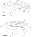
Fig. 3 est une vue isométrique de ladite montre, les éléments d'habillage ayant été supprimés ; et -
Fig. 4 est une vue similaire à celle de lafig. 3 , la bague porte-fond ainsi que la planche de support étant représentées.
-
Fig. 1 is an isometric view cut from a watch according to the invention; -
Fig. 2 is an isometric view of the stamp, heel, support etc. of said watch; -
Fig. 3 is an isometric view of said watch, the covering elements having been removed; and -
Fig. 4 is a view similar to that of thefig. 3 , the bottom support ring and the support board being shown.
Les
Le fond 7 comporte des ouvertures 7a qui permettent le passage d'ondes sonores, et le boitier est rendu étanche par l'intermédiaire d'une membrane 8 tenue en sandwich entre le fond 7 et une bague porte-fond 10 qui est elle-même solidaire de la carrure 3. Divers joints d'étanchéité 14 sont prévus de manière classique afin de rendre la membrane 8 étanche par rapport à la bague porte-fond 10 et également de rendre cette dernière étanche par rapport à la carrure. D'autres constructions sont également possibles. Par exemple, la membrane 8 peut être soudée ou collée sur la bague porte-fond 10 ou le fond 7 peut être fixé directement sur la carrure 3, la membrane 8 étant tenue en sandwich entre ces deux éléments. On note que la membrane 8 peut être faite en métal (notamment en titane ou en métal amorphe), polymère, ou tout autre matériau connu de l'homme du métier pour cette application.The
Le boitier loge un mouvement 13, qui peut être de genre mécanique, électrique, électronique ou hybride. Dans le mode de réalisation illustré, le mouvement 13 est mécanique et à remontage automatique, un dispositif de remontage automatique étant disposé côté fond du mouvement 13 et agencé pour remonter un barillet que comporte le mouvement 11.The case houses a
Le mouvement 13 est lié à un bâti 12 qui est fixé dans la carrure de manière conventionnelle et qui supporte un mécanisme de sonnerie 21. Le bâti 12 définit au moins partiellement une cavité périphérique 15 dans laquelle se situent au moins partiellement un talon 17 ainsi qu'un timbre 19 solidaire dudit talon 17. Cette cavité 15 sert en tant que caisse de résonance et, dans une variante de construction non représentée, au moins une partie de la cavité 15 peut être constituée par un interstice annulaire formée entre, d'une part, la paroi extérieure du bâti 12 et, d'autre part, la paroi interne de la carrure 3. Dans un tel cas, le talon 17 et le timbre 19 peuvent être contenus au moins partiellement dans cet interstice.The
Le timbre 19 est agencé pour être frappé par un marteau 21a (voir la
Afin de supporter le talon 17, ce dernier est associé à un support 23 et est fixé à une partie mobile 23a que comporte ce dernier. Dans le mode de réalisation illustré, le talon 17 est fixé sur ladite partie mobile 23a par l'intermédiaire de vis (alors non visibles), par soudage ou par collage. Il est également possible que le talon 17 puisse être intégré à la partie mobile 23a en étant venu de matière avec cette partie mobile 23a. Ce faisant, le talon 17 ainsi que le timbre 19 sont entièrement libres de tout contact avec un autre élément que ladite partie mobile 23a, et sont ainsi suspendus par le support 23 ; la grande majorité des vibrations du talon 17, engendrées par le timbre 19, étant ainsi transmises à la partie mobile 23a du support 23.In order to support the
Cependant, dans une variante non illustrée, il est également possible que le talon 17 puisse être fixé à un autre élément fixe tel qu'un élément de bâti 12, la carrure 3 ou similaire, ladite partie mobile 23a étant en contact avec ledit talon 17. Néanmoins, même si un tel agencement alternatif représente une amélioration par rapport à l'art antérieur, les résultats sont mitigés par rapport à la variante illustrée puisqu'une partie, non négligeable, des vibrations du talon 17 seront perdues à cause de l'interaction entre le talon 17 et l'élément fixe duquel il est solidaire.However, in a variant not illustrated, it is also possible that the
La partie mobile 23a du support 23 est suspendue sur le bâti par l'intermédiaire de deux barres de torsion 23b s'étendant chacune entre ladite partie mobile 23a et un élément de fixation 23c correspondant. Ces deux éléments de fixation 23c se situant de part et d'autre de ladite partie mobile 23a, et sont agencés pour être fixés à un élément de bâti 12 ou du boitier (par exemple la carrure 3).The
Dans le mode de réalisation illustré, les éléments de fixation 23c sont vissés sur le bâti 12 (voir la
Alternativement, les barres de torsion 23b peuvent être remplacées par une rotule flexible, un pivot RCC (« remote centre compliance ») ou autre guidage flexible ad hoc fixé à la carrure 3 ou à un élément de bâti, ou même une charnière à goupille munie d'un ressort de rappel. En matière de pivots flexibles, la demanderesse fait référence à l'ouvrage
Un pont de transmission sonore 25 est fixé à son extrémité proximale 25a à ladite partie mobile 23a, en étant vissé, collé, soudé ou similaire à cette dernière. Ledit pont 25 est de forme allongée et s'étend dans l'interstice formé entre le mouvement 13 et la membrane 8, en étant en contact permanent avec cette dernière en une zone de contact prédéterminé près de son extrémité distale 25b, qui est son extrémité libre. Ce contact peut être, bien entendu, direct ou indirect par l'intermédiaire d'un élément intermédiaire quelconque.A
À cet effet, ladite extrémité distale 25b peut porter un plot 25c réglable (voir la
Avantageusement, ladite zone de contact se situe substantiellement au milieu de la membrane 8, ou au moins à l'intérieur d'un rayon de 50%, 75% ou même 90% inférieur à celui de la membrane 8, mais rien n'empêche que le contact puisse être plus proche du pourtour de cette dernière.Advantageously, said contact zone is located substantially in the middle of the
On note par ailleurs que la membrane 8 peut être rendue solidaire de l'extrémité distale 25b du pont 25 par l'intermédiaire d'une vis, d'un soudage, d'un rivage, d'un rivet, par de la colle ou par tout autre moyen approprié.It should also be noted that the
Puisque la partie mobile 23a du support est supportée de manière à pivoter autour d'un seul axe de rotation 23d substantiellement parallèle au plan de la membrane 8, et que le pont 25 est plus long que la distance entre l'axe 23d et le point d'attache du timbre 19 au talon 17, le pont sert de transformateur de la direction d'action des vibrations du timbre 19. Ces vibrations s'effectuent principalement (mais pas exclusivement) dans le plan du timbre 19, notamment puisqu'il est frappé par le marteau 21a selon une direction qui se trouve dans ce même plan. Cependant, la direction optimale d'excitation de la membrane 8 est perpendiculaire au plan de cette dernière, c'est-à-dire orthogonal aux vibrations principales du timbre 19. La forme substantiellement en « L » de l'ensemble pont 25 - partie mobile 23a modifie ainsi la direction d'action des vibrations par 90°, afin de mieux faire vibrer la membrane 8 de manière optimale.Since the
Par ailleurs, la forme allongée dudit pont de transmission 25 peut agir comme amplificateur mécanique, l'amplitude des vibrations du talon 17 étant magnifiées à raison du rapport entre, d'une part, le bras de levier de la zone de contact entre le pont 25 et la membrane 8 et, d'autre part, le bras de levier du timbre, selon la loi élémentaire des leviers. Ces bras de levier sont représentés schématiquement sur la
Des essais auditifs comparatifs ont montré que l'agencement de l'invention augmente le volume sonore perceptible de manière significative par rapport à une montre à sonnerie classique.Comparative hearing tests have shown that the arrangement of the invention increases the perceptible sound volume significantly compared to a conventional striking watch.
Afin de protéger la membrane 8 d'une surpression, par exemple lors d'une plongée, la bague porte-fond 10 est venue de matière avec une planche de support 29, munie d'ouvertures 29a qui traversent son épaisseur pour permettre la transmission d'ondes sonores depuis l'intérieur de la boite à la membrane 8. Lors d'une plongée, par exemple, la membrane 8 est poussée par la pression de l'eau ambiante contre ladite planche 29, ce qui limite son débattement et ainsi les contraintes qu'elle subit.In order to protect the
Bien qu'il soit possible d'agencer la planche 29 de telle sorte que seule l'extrémité distale 25c du pont de transmission 25 la traverse, il est avantageux de prévoir une ouverture 29b en forme de fente allongée agencée pour loger au moins partiellement ledit pont de transmission 25 dans l'épaisseur de ladite planche 29. Ce faisant, la hauteur du système peut être minimisée.Although it is possible to arrange the
Il va sans dire que la planche de support 29 peut alternativement être formée d'une pièce séparée, fixée à ladite bague porte-fond 10, ou, en l'absence de cette dernière (par exemple dans le cas où la carrure 3 porte directement le fond 7), peut être un élément fixé à la carrure 3 ou au fond 7, ou tenu en sandwich entre ces derniers. Ceci étant dit, la présence de ladite planche 29 n'est pas obligatoire.It goes without saying that the
Bien que l'invention ait été décrite ci-dessus en lien avec des modes de réalisation spécifiques, des variantes supplémentaires sont également envisageables sans sortir de la portée de l'invention comme définie par les revendications.Although the invention has been described above in connection with specific embodiments, additional variants are also possible without departing from the scope of the invention as defined by the claims.
Claims (10)
et en ce qu'un pont de transmission sonore (25) est solidaire de ladite partie mobile (23a), ledit pont de transmission (25) s'étendant dans un interstice formé entre ledit mouvement (13) et ladite membrane (8) et comprenant une extrémité libre (25b) en contact avec ladite membrane (8) en une zone de contact prédéfinie.Watch (1) with striking mechanism comprising:
and in that a sound transmission bridge (25) is integral with said movable part (23a), said transmission bridge (25) extending in a gap formed between said movement (13) and said membrane (8) and comprising a free end (25b) in contact with said membrane (8) in a predefined contact zone.
Applications Claiming Priority (1)
| Application Number | Priority Date | Filing Date | Title |
|---|---|---|---|
| CH01303/18A CH715470A1 (en) | 2018-10-25 | 2018-10-25 | Ringing watch. |
Publications (2)
| Publication Number | Publication Date |
|---|---|
| EP3644133A1 true EP3644133A1 (en) | 2020-04-29 |
| EP3644133B1 EP3644133B1 (en) | 2021-08-18 |
Family
ID=64745817
Family Applications (1)
| Application Number | Title | Priority Date | Filing Date |
|---|---|---|---|
| EP19205084.7A Active EP3644133B1 (en) | 2018-10-25 | 2019-10-24 | Chiming watch |
Country Status (2)
| Country | Link |
|---|---|
| EP (1) | EP3644133B1 (en) |
| CH (1) | CH715470A1 (en) |
Cited By (3)
| Publication number | Priority date | Publication date | Assignee | Title |
|---|---|---|---|---|
| WO2022002622A1 (en) | 2020-07-01 | 2022-01-06 | Patek Philippe Sa Genève | Timepiece comprising a vibration-amplifying device |
| EP4167032A1 (en) | 2021-10-14 | 2023-04-19 | Manufacture et fabrique de montres et chronomètres, Ulysse Nardin Le Locle S.A. | Chiming timepiece |
| EP4167033A1 (en) * | 2021-10-18 | 2023-04-19 | Patek Philippe SA Genève | Bell and lug assembly for a chiming mechanism of a timepiece |
Citations (5)
| Publication number | Priority date | Publication date | Assignee | Title |
|---|---|---|---|---|
| FR1042749A (en) | 1949-09-17 | 1953-11-03 | Junghans Geb Ag | Alarm clock watch |
| FR2777095A1 (en) | 1998-04-02 | 1999-10-08 | Christophe Claret Sa | Watch with much louder audible alarms and time periods |
| CH698742B1 (en) | 2005-09-28 | 2009-10-15 | Richemont Int Sa | Strike sounding spring connecting device for e.g. wristwatch, has elastic ring with external edge locked between bezel and middle of timepiece, where ring's part not located below glass is entirely housed below bezel |
| EP2942675A1 (en) | 2014-05-07 | 2015-11-11 | Société anonyme de la Manufacture d'Horlogerie Audemars Piguet & Cie | Chiming watch |
| CH710200A2 (en) | 2014-10-01 | 2016-04-15 | Montres Breguet Sa | watch bezel for musical shows. |
-
2018
- 2018-10-25 CH CH01303/18A patent/CH715470A1/en unknown
-
2019
- 2019-10-24 EP EP19205084.7A patent/EP3644133B1/en active Active
Patent Citations (5)
| Publication number | Priority date | Publication date | Assignee | Title |
|---|---|---|---|---|
| FR1042749A (en) | 1949-09-17 | 1953-11-03 | Junghans Geb Ag | Alarm clock watch |
| FR2777095A1 (en) | 1998-04-02 | 1999-10-08 | Christophe Claret Sa | Watch with much louder audible alarms and time periods |
| CH698742B1 (en) | 2005-09-28 | 2009-10-15 | Richemont Int Sa | Strike sounding spring connecting device for e.g. wristwatch, has elastic ring with external edge locked between bezel and middle of timepiece, where ring's part not located below glass is entirely housed below bezel |
| EP2942675A1 (en) | 2014-05-07 | 2015-11-11 | Société anonyme de la Manufacture d'Horlogerie Audemars Piguet & Cie | Chiming watch |
| CH710200A2 (en) | 2014-10-01 | 2016-04-15 | Montres Breguet Sa | watch bezel for musical shows. |
Cited By (4)
| Publication number | Priority date | Publication date | Assignee | Title |
|---|---|---|---|---|
| WO2022002622A1 (en) | 2020-07-01 | 2022-01-06 | Patek Philippe Sa Genève | Timepiece comprising a vibration-amplifying device |
| EP4167032A1 (en) | 2021-10-14 | 2023-04-19 | Manufacture et fabrique de montres et chronomètres, Ulysse Nardin Le Locle S.A. | Chiming timepiece |
| WO2023062117A1 (en) | 2021-10-14 | 2023-04-20 | Manufacture Et Fabrique De Montres Et Chronomètres Ulysse Nardin Le Locle S.A. | Chiming timepiece |
| EP4167033A1 (en) * | 2021-10-18 | 2023-04-19 | Patek Philippe SA Genève | Bell and lug assembly for a chiming mechanism of a timepiece |
Also Published As
| Publication number | Publication date |
|---|---|
| CH715470A1 (en) | 2020-04-30 |
| EP3644133B1 (en) | 2021-08-18 |
Similar Documents
| Publication | Publication Date | Title |
|---|---|---|
| EP3644133B1 (en) | Chiming watch | |
| EP2367078B1 (en) | Alarm watch provided with an acoustic membrane | |
| CH698533B1 (en) | Device for fixing at least one ringing tone in a timepiece and a method of attaching at least one ringing tone in a timepiece. | |
| EP3002639B1 (en) | Musical watch bezel with improved acoustic performance | |
| EP3537229B1 (en) | Musical watch case | |
| EP2942675B1 (en) | Chiming watch | |
| EP2461220B1 (en) | Acoustic membrane for a musical box or an alarm watch | |
| EP2367079B1 (en) | Glass-bezel assembly for a timepiece and assembly method | |
| EP2207069B1 (en) | Element for supporting striking gongs in a timepiece | |
| EP3525045A1 (en) | Chiming timepiece | |
| WO2017071903A1 (en) | Watch with improved tightness | |
| CH698742B1 (en) | Strike sounding spring connecting device for e.g. wristwatch, has elastic ring with external edge locked between bezel and middle of timepiece, where ring's part not located below glass is entirely housed below bezel | |
| EP2034376B1 (en) | Watch case | |
| EP3812844B1 (en) | Timepiece comprising a device for amplifying vibrations | |
| CH714758A2 (en) | Musical watch box. | |
| EP3696618A1 (en) | Chiming or musical watch with arrangement for guiding the acoustic waves | |
| WO2022002622A1 (en) | Timepiece comprising a vibration-amplifying device | |
| CH702840B1 (en) | Together trim crystal-bezel timepiece and assembly process. | |
| CH710200B1 (en) | Watch bezel for musical watch. | |
| CH520357A (en) | Wristwatch-alarm clock | |
| CH716149A1 (en) | Clockwork movement comprising at least one gong. | |
| CH259170A (en) | Alarm clock. | |
| CH715841B1 (en) | Chiming or musical watch with arrangement for guiding acoustic waves. | |
| CH696563A5 (en) | Resonator for a timepiece. | |
| CH699881A2 (en) | Watch i.e. wristwatch, has sound guiding unit in direct contact with region near opening in side wall of watch case for guiding sound waves to guiding channel to eliminate parasite reflection cavities, edges and surfaces in region |
Legal Events
| Date | Code | Title | Description |
|---|---|---|---|
| PUAI | Public reference made under article 153(3) epc to a published international application that has entered the european phase |
Free format text: ORIGINAL CODE: 0009012 |
|
| STAA | Information on the status of an ep patent application or granted ep patent |
Free format text: STATUS: THE APPLICATION HAS BEEN PUBLISHED |
|
| AK | Designated contracting states |
Kind code of ref document: A1 Designated state(s): AL AT BE BG CH CY CZ DE DK EE ES FI FR GB GR HR HU IE IS IT LI LT LU LV MC MK MT NL NO PL PT RO RS SE SI SK SM TR |
|
| AX | Request for extension of the european patent |
Extension state: BA ME |
|
| STAA | Information on the status of an ep patent application or granted ep patent |
Free format text: STATUS: REQUEST FOR EXAMINATION WAS MADE |
|
| 17P | Request for examination filed |
Effective date: 20201012 |
|
| RBV | Designated contracting states (corrected) |
Designated state(s): AL AT BE BG CH CY CZ DE DK EE ES FI FR GB GR HR HU IE IS IT LI LT LU LV MC MK MT NL NO PL PT RO RS SE SI SK SM TR |
|
| GRAP | Despatch of communication of intention to grant a patent |
Free format text: ORIGINAL CODE: EPIDOSNIGR1 |
|
| STAA | Information on the status of an ep patent application or granted ep patent |
Free format text: STATUS: GRANT OF PATENT IS INTENDED |
|
| INTG | Intention to grant announced |
Effective date: 20210303 |
|
| GRAS | Grant fee paid |
Free format text: ORIGINAL CODE: EPIDOSNIGR3 |
|
| GRAA | (expected) grant |
Free format text: ORIGINAL CODE: 0009210 |
|
| STAA | Information on the status of an ep patent application or granted ep patent |
Free format text: STATUS: THE PATENT HAS BEEN GRANTED |
|
| AK | Designated contracting states |
Kind code of ref document: B1 Designated state(s): AL AT BE BG CH CY CZ DE DK EE ES FI FR GB GR HR HU IE IS IT LI LT LU LV MC MK MT NL NO PL PT RO RS SE SI SK SM TR |
|
| REG | Reference to a national code |
Ref country code: GB Ref legal event code: FG4D Free format text: NOT ENGLISH |
|
| REG | Reference to a national code |
Ref country code: CH Ref legal event code: EP |
|
| REG | Reference to a national code |
Ref country code: DE Ref legal event code: R096 Ref document number: 602019006958 Country of ref document: DE |
|
| REG | Reference to a national code |
Ref country code: IE Ref legal event code: FG4D Free format text: LANGUAGE OF EP DOCUMENT: FRENCH Ref country code: AT Ref legal event code: REF Ref document number: 1422182 Country of ref document: AT Kind code of ref document: T Effective date: 20210915 |
|
| REG | Reference to a national code |
Ref country code: LT Ref legal event code: MG9D |
|
| REG | Reference to a national code |
Ref country code: NL Ref legal event code: MP Effective date: 20210818 |
|
| REG | Reference to a national code |
Ref country code: AT Ref legal event code: MK05 Ref document number: 1422182 Country of ref document: AT Kind code of ref document: T Effective date: 20210818 |
|
| PG25 | Lapsed in a contracting state [announced via postgrant information from national office to epo] |
Ref country code: SE Free format text: LAPSE BECAUSE OF FAILURE TO SUBMIT A TRANSLATION OF THE DESCRIPTION OR TO PAY THE FEE WITHIN THE PRESCRIBED TIME-LIMIT Effective date: 20210818 Ref country code: RS Free format text: LAPSE BECAUSE OF FAILURE TO SUBMIT A TRANSLATION OF THE DESCRIPTION OR TO PAY THE FEE WITHIN THE PRESCRIBED TIME-LIMIT Effective date: 20210818 Ref country code: ES Free format text: LAPSE BECAUSE OF FAILURE TO SUBMIT A TRANSLATION OF THE DESCRIPTION OR TO PAY THE FEE WITHIN THE PRESCRIBED TIME-LIMIT Effective date: 20210818 Ref country code: BG Free format text: LAPSE BECAUSE OF FAILURE TO SUBMIT A TRANSLATION OF THE DESCRIPTION OR TO PAY THE FEE WITHIN THE PRESCRIBED TIME-LIMIT Effective date: 20211118 Ref country code: AT Free format text: LAPSE BECAUSE OF FAILURE TO SUBMIT A TRANSLATION OF THE DESCRIPTION OR TO PAY THE FEE WITHIN THE PRESCRIBED TIME-LIMIT Effective date: 20210818 Ref country code: LT Free format text: LAPSE BECAUSE OF FAILURE TO SUBMIT A TRANSLATION OF THE DESCRIPTION OR TO PAY THE FEE WITHIN THE PRESCRIBED TIME-LIMIT Effective date: 20210818 Ref country code: NO Free format text: LAPSE BECAUSE OF FAILURE TO SUBMIT A TRANSLATION OF THE DESCRIPTION OR TO PAY THE FEE WITHIN THE PRESCRIBED TIME-LIMIT Effective date: 20211118 Ref country code: PT Free format text: LAPSE BECAUSE OF FAILURE TO SUBMIT A TRANSLATION OF THE DESCRIPTION OR TO PAY THE FEE WITHIN THE PRESCRIBED TIME-LIMIT Effective date: 20211220 Ref country code: HR Free format text: LAPSE BECAUSE OF FAILURE TO SUBMIT A TRANSLATION OF THE DESCRIPTION OR TO PAY THE FEE WITHIN THE PRESCRIBED TIME-LIMIT Effective date: 20210818 Ref country code: FI Free format text: LAPSE BECAUSE OF FAILURE TO SUBMIT A TRANSLATION OF THE DESCRIPTION OR TO PAY THE FEE WITHIN THE PRESCRIBED TIME-LIMIT Effective date: 20210818 |
|
| PG25 | Lapsed in a contracting state [announced via postgrant information from national office to epo] |
Ref country code: PL Free format text: LAPSE BECAUSE OF FAILURE TO SUBMIT A TRANSLATION OF THE DESCRIPTION OR TO PAY THE FEE WITHIN THE PRESCRIBED TIME-LIMIT Effective date: 20210818 Ref country code: LV Free format text: LAPSE BECAUSE OF FAILURE TO SUBMIT A TRANSLATION OF THE DESCRIPTION OR TO PAY THE FEE WITHIN THE PRESCRIBED TIME-LIMIT Effective date: 20210818 Ref country code: GR Free format text: LAPSE BECAUSE OF FAILURE TO SUBMIT A TRANSLATION OF THE DESCRIPTION OR TO PAY THE FEE WITHIN THE PRESCRIBED TIME-LIMIT Effective date: 20211119 |
|
| PG25 | Lapsed in a contracting state [announced via postgrant information from national office to epo] |
Ref country code: NL Free format text: LAPSE BECAUSE OF FAILURE TO SUBMIT A TRANSLATION OF THE DESCRIPTION OR TO PAY THE FEE WITHIN THE PRESCRIBED TIME-LIMIT Effective date: 20210818 |
|
| PG25 | Lapsed in a contracting state [announced via postgrant information from national office to epo] |
Ref country code: DK Free format text: LAPSE BECAUSE OF FAILURE TO SUBMIT A TRANSLATION OF THE DESCRIPTION OR TO PAY THE FEE WITHIN THE PRESCRIBED TIME-LIMIT Effective date: 20210818 |
|
| REG | Reference to a national code |
Ref country code: DE Ref legal event code: R119 Ref document number: 602019006958 Country of ref document: DE |
|
| PG25 | Lapsed in a contracting state [announced via postgrant information from national office to epo] |
Ref country code: SM Free format text: LAPSE BECAUSE OF FAILURE TO SUBMIT A TRANSLATION OF THE DESCRIPTION OR TO PAY THE FEE WITHIN THE PRESCRIBED TIME-LIMIT Effective date: 20210818 Ref country code: SK Free format text: LAPSE BECAUSE OF FAILURE TO SUBMIT A TRANSLATION OF THE DESCRIPTION OR TO PAY THE FEE WITHIN THE PRESCRIBED TIME-LIMIT Effective date: 20210818 Ref country code: RO Free format text: LAPSE BECAUSE OF FAILURE TO SUBMIT A TRANSLATION OF THE DESCRIPTION OR TO PAY THE FEE WITHIN THE PRESCRIBED TIME-LIMIT Effective date: 20210818 Ref country code: EE Free format text: LAPSE BECAUSE OF FAILURE TO SUBMIT A TRANSLATION OF THE DESCRIPTION OR TO PAY THE FEE WITHIN THE PRESCRIBED TIME-LIMIT Effective date: 20210818 Ref country code: CZ Free format text: LAPSE BECAUSE OF FAILURE TO SUBMIT A TRANSLATION OF THE DESCRIPTION OR TO PAY THE FEE WITHIN THE PRESCRIBED TIME-LIMIT Effective date: 20210818 Ref country code: AL Free format text: LAPSE BECAUSE OF FAILURE TO SUBMIT A TRANSLATION OF THE DESCRIPTION OR TO PAY THE FEE WITHIN THE PRESCRIBED TIME-LIMIT Effective date: 20210818 |
|
| REG | Reference to a national code |
Ref country code: BE Ref legal event code: MM Effective date: 20211031 |
|
| PLBE | No opposition filed within time limit |
Free format text: ORIGINAL CODE: 0009261 |
|
| STAA | Information on the status of an ep patent application or granted ep patent |
Free format text: STATUS: NO OPPOSITION FILED WITHIN TIME LIMIT |
|
| PG25 | Lapsed in a contracting state [announced via postgrant information from national office to epo] |
Ref country code: MC Free format text: LAPSE BECAUSE OF FAILURE TO SUBMIT A TRANSLATION OF THE DESCRIPTION OR TO PAY THE FEE WITHIN THE PRESCRIBED TIME-LIMIT Effective date: 20210818 |
|
| 26N | No opposition filed |
Effective date: 20220519 |
|
| PG25 | Lapsed in a contracting state [announced via postgrant information from national office to epo] |
Ref country code: LU Free format text: LAPSE BECAUSE OF NON-PAYMENT OF DUE FEES Effective date: 20211024 Ref country code: IT Free format text: LAPSE BECAUSE OF FAILURE TO SUBMIT A TRANSLATION OF THE DESCRIPTION OR TO PAY THE FEE WITHIN THE PRESCRIBED TIME-LIMIT Effective date: 20210818 Ref country code: DE Free format text: LAPSE BECAUSE OF NON-PAYMENT OF DUE FEES Effective date: 20220503 Ref country code: BE Free format text: LAPSE BECAUSE OF NON-PAYMENT OF DUE FEES Effective date: 20211031 |
|
| PG25 | Lapsed in a contracting state [announced via postgrant information from national office to epo] |
Ref country code: SI Free format text: LAPSE BECAUSE OF FAILURE TO SUBMIT A TRANSLATION OF THE DESCRIPTION OR TO PAY THE FEE WITHIN THE PRESCRIBED TIME-LIMIT Effective date: 20210818 |
|
| PG25 | Lapsed in a contracting state [announced via postgrant information from national office to epo] |
Ref country code: FR Free format text: LAPSE BECAUSE OF NON-PAYMENT OF DUE FEES Effective date: 20211031 |
|
| PG25 | Lapsed in a contracting state [announced via postgrant information from national office to epo] |
Ref country code: IE Free format text: LAPSE BECAUSE OF NON-PAYMENT OF DUE FEES Effective date: 20211024 |
|
| PG25 | Lapsed in a contracting state [announced via postgrant information from national office to epo] |
Ref country code: CY Free format text: LAPSE BECAUSE OF FAILURE TO SUBMIT A TRANSLATION OF THE DESCRIPTION OR TO PAY THE FEE WITHIN THE PRESCRIBED TIME-LIMIT Effective date: 20210818 |
|
| PG25 | Lapsed in a contracting state [announced via postgrant information from national office to epo] |
Ref country code: HU Free format text: LAPSE BECAUSE OF FAILURE TO SUBMIT A TRANSLATION OF THE DESCRIPTION OR TO PAY THE FEE WITHIN THE PRESCRIBED TIME-LIMIT; INVALID AB INITIO Effective date: 20191024 |
|
| PGFP | Annual fee paid to national office [announced via postgrant information from national office to epo] |
Ref country code: CH Payment date: 20231102 Year of fee payment: 5 |