EP2034376B1 - Watch case - Google Patents
Watch case Download PDFInfo
- Publication number
- EP2034376B1 EP2034376B1 EP20070405272 EP07405272A EP2034376B1 EP 2034376 B1 EP2034376 B1 EP 2034376B1 EP 20070405272 EP20070405272 EP 20070405272 EP 07405272 A EP07405272 A EP 07405272A EP 2034376 B1 EP2034376 B1 EP 2034376B1
- Authority
- EP
- European Patent Office
- Prior art keywords
- watch case
- bezel
- case according
- watch
- wall
- Prior art date
- Legal status (The legal status is an assumption and is not a legal conclusion. Google has not performed a legal analysis and makes no representation as to the accuracy of the status listed.)
- Active
Links
- 239000007787 solid Substances 0.000 claims 2
- 208000003643 Callosities Diseases 0.000 claims 1
- 206010020649 Hyperkeratosis Diseases 0.000 claims 1
- 240000008042 Zea mays Species 0.000 claims 1
- 235000005824 Zea mays ssp. parviglumis Nutrition 0.000 claims 1
- 235000002017 Zea mays subsp mays Nutrition 0.000 claims 1
- 235000005822 corn Nutrition 0.000 claims 1
- 230000014759 maintenance of location Effects 0.000 claims 1
- 230000005540 biological transmission Effects 0.000 description 8
- 239000000463 material Substances 0.000 description 4
- 238000004519 manufacturing process Methods 0.000 description 3
- 210000000056 organ Anatomy 0.000 description 3
- 230000003321 amplification Effects 0.000 description 2
- 230000008901 benefit Effects 0.000 description 2
- 239000000428 dust Substances 0.000 description 2
- 230000000694 effects Effects 0.000 description 2
- 229910052751 metal Inorganic materials 0.000 description 2
- 239000002184 metal Substances 0.000 description 2
- 238000003199 nucleic acid amplification method Methods 0.000 description 2
- 230000001737 promoting effect Effects 0.000 description 2
- 238000009877 rendering Methods 0.000 description 2
- XLYOFNOQVPJJNP-UHFFFAOYSA-N water Substances O XLYOFNOQVPJJNP-UHFFFAOYSA-N 0.000 description 2
- 241001080024 Telles Species 0.000 description 1
- 238000010521 absorption reaction Methods 0.000 description 1
- 239000000956 alloy Substances 0.000 description 1
- 229910045601 alloy Inorganic materials 0.000 description 1
- 230000004888 barrier function Effects 0.000 description 1
- 239000000919 ceramic Substances 0.000 description 1
- 239000000470 constituent Substances 0.000 description 1
- 238000013016 damping Methods 0.000 description 1
- 238000005553 drilling Methods 0.000 description 1
- 230000003100 immobilizing effect Effects 0.000 description 1
- 229910052500 inorganic mineral Inorganic materials 0.000 description 1
- 230000010354 integration Effects 0.000 description 1
- 239000007788 liquid Substances 0.000 description 1
- 239000012528 membrane Substances 0.000 description 1
- 150000002739 metals Chemical class 0.000 description 1
- 238000000034 method Methods 0.000 description 1
- 239000011707 mineral Substances 0.000 description 1
- 239000002245 particle Substances 0.000 description 1
- 230000001681 protective effect Effects 0.000 description 1
- 230000002787 reinforcement Effects 0.000 description 1
- 229910052594 sapphire Inorganic materials 0.000 description 1
- 239000010980 sapphire Substances 0.000 description 1
- 238000007789 sealing Methods 0.000 description 1
- 230000035939 shock Effects 0.000 description 1
- 238000003466 welding Methods 0.000 description 1
- 210000000707 wrist Anatomy 0.000 description 1
Images


Classifications
-
- G—PHYSICS
- G04—HOROLOGY
- G04B—MECHANICALLY-DRIVEN CLOCKS OR WATCHES; MECHANICAL PARTS OF CLOCKS OR WATCHES IN GENERAL; TIME PIECES USING THE POSITION OF THE SUN, MOON OR STARS
- G04B19/00—Indicating the time by visual means
- G04B19/28—Adjustable guide marks or pointers for indicating determined points of time
-
- G—PHYSICS
- G04—HOROLOGY
- G04B—MECHANICALLY-DRIVEN CLOCKS OR WATCHES; MECHANICAL PARTS OF CLOCKS OR WATCHES IN GENERAL; TIME PIECES USING THE POSITION OF THE SUN, MOON OR STARS
- G04B23/00—Arrangements producing acoustic signals at preselected times
- G04B23/02—Alarm clocks
- G04B23/028—Sounding bodies; boxes used as sounding cases; fixation on or in the case
-
- G—PHYSICS
- G04—HOROLOGY
- G04B—MECHANICALLY-DRIVEN CLOCKS OR WATCHES; MECHANICAL PARTS OF CLOCKS OR WATCHES IN GENERAL; TIME PIECES USING THE POSITION OF THE SUN, MOON OR STARS
- G04B23/00—Arrangements producing acoustic signals at preselected times
- G04B23/02—Alarm clocks
- G04B23/12—Alarm watches to be worn in pockets or on the wrist
-
- G—PHYSICS
- G04—HOROLOGY
- G04B—MECHANICALLY-DRIVEN CLOCKS OR WATCHES; MECHANICAL PARTS OF CLOCKS OR WATCHES IN GENERAL; TIME PIECES USING THE POSITION OF THE SUN, MOON OR STARS
- G04B37/00—Cases
- G04B37/0075—Cases with means to enhance sound transmission
Definitions
- the subject of the present invention is a watch case, preferably a resonant wristwatch box, in particular a resonant box for a striking watch.
- the bell wristwatches are provided with a sound generating member which may typically consist of at least one stamp or gong struck by a hammer, or even a disc or pin roll actuating lamellae at the same time. way of a music box.
- a sound generating member which may typically consist of at least one stamp or gong struck by a hammer, or even a disc or pin roll actuating lamellae at the same time. way of a music box.
- the watch may be able to produce sounds or melodies on demand or at regular intervals of time.
- Such watches are for example repeating watches, so-called big rings, chimes or gongs.
- the document FR 2,777,095 suggests a sound watch comprising, inside its housing, at least one resonance chamber on the wall of which the sound production unit is directly mounted thereon.
- a plurality of such chambers may be interconnected by tubular transmission members.
- some of these rooms may even be provided with openings to the outside of the housing.
- the bottom and the middle of the watch case are connected to each other by means suitable for damping the vibrations generated by the sound production unit. Thus, these vibrations are not transmitted or only weakly to the middle part and the parts connected thereto.
- the main disadvantage of this device lies in the fact that one or more voids, closed by walls, must be reserved for within the housing to be able to create the corresponding resonance chamber or chambers. This results in a loss of space to the detriment of that occupied by other organs or the need to have to use larger volume watch cases.
- the resonance of a watch case is a property generally related to watches called ringing. However, this quality could also be appreciated by collectors for watches devoid of any ringtone or specific melody. In such a case, it will be sought that the housing can at best transmit and sound the clicking of the mechanism and the regular beats of the balance. This is the reason why the object of the present invention is not limited to the use of the object described below for ringtones, but also relates to its use for other mechanical watches, essentially .
- the object of the present invention is to remedy at least in part the aforementioned drawbacks by suggesting a watch case formed of three main distinct parts, namely a bezel, a middle and a bottom.
- this bottom has the particularity of being connected to the bezel outside the caseband, trapping the latter inside a protective zone, preferably perforated.
- the middle part can consist essentially of a wall of small or very thin, while remaining immune to any impact from the outside of the housing.
- the document CH 645236 discloses a watch having assembly means arranged outside the middle part.
- the object of the present invention is preferably to equip wristwatch watches.
- the subject of the present invention is a watch case according to claim 1.
- the arrangement of a middle part of very small thickness makes it possible to minimize the sound barrier effect existing between the interior and exterior environments of the case.
- the present watch case has characteristics that best promote the transmission of sound waves through the middle part, without having amplified them by successive reflections.
- the sound box role played by the watch case in the amplification of sound is further improved in the present invention by the specific arrangement outside the middle part of the assembly means that hold the middle part, the bottom and the bezel.
- this arrangement also constitutes a means or a protection zone of the middle part against any possible impact.
- the watch case can nevertheless be sealed to liquids and fine dust particles, through seals disposed between the middle part, the bezel and the bottom.
- this watch case is intended to receive a ringing movement whose sound generating member may be either integral with the movement or held directly on the middle part so as to maximize the perceived loudness outside. of the case.
- the object of the present invention is intended to be worn on the wrist by means of a bracelet maintained with hooking horns.
- the latter are each formed of one or two parts attached to the telescope and / or the bottom. Alternatively, this or these parts may constitute with the bezel and / or the bottom of the same part machined in the mass.
- the present invention also refers to a use of said case for a ring watch or a wristwatch, preferably a ringing wristwatch.
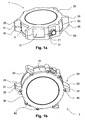
- FIGS 1a and 1b these schematically illustrate a resonant housing according to the present invention.
- This housing 1 is formed of three distinct main parts, namely a middle part 10, a bezel 20 and a bottom 30.
- the caseband is immobilized between the bezel and the bottom themselves held together by assembly means 40.
- the telescope 20 and the bottom 30 are connected to each other outside the middle part 10 surrounding the latter.
- the telescope and / or the base comprise excrescences, for example in the form of portions of uprights 21, 31. These amounts respectively fill the periphery of the telescope and that of the bottom, so as to face to assemble in pairs, preferably in the horizontal plane of the middle part 10.
- the middle part is trapped and partly protected by the assembly bezel-bottom.
- This assembly is held together by a plurality of screws 42 whose heads preferably appear on the bottom of the housing 1.
- these assembly means do not pass through the space located inside the middle part 10, nor this middle part itself, but instead are arranged close to the outer periphery of the middle part.
- the portions of uprights 21, 31 are further apart from the middle part, so that a gap 9 exists between these uprights and this middle part.
- this one illustrates by a schematic view, an exploded perspective of the watch case represented in Figures 1a and 1b .
- the bezel 20 is closed by an upper window 2 inserted in a shoulder 22.
- the latter is located on the upper inner edge of the opening in the bezel.
- a seal 4 takes place between the upper window 2 and the shoulder 22.
- the upper window makes it possible to see the dial 8 illustrated here as an indication.
- the housing 1 is closed at its bottom by a lower window 3, clamped in the same manner in a second shoulder 32, itself provided on the inner edge and upper of the opening made in the bottom 30 A second seal 5 is inserted between the lower window 3 and the shoulder 32.
- This second mirror makes it possible to see the non-illustrated movement of the watch, in particular the wheel side which comprises the plate supporting the gear trains and the bridges. .
- this lower window 3 is optional and could be replaced by an opaque closure, which could still be one with the bottom 30 so as to constitute one and the same piece.
- the middle part 10 which is wrapped at least partially by the bezel and the bottom.
- the middle part 10 may advantageously consist of a wall 11 of small or very small thickness, to promote as much as possible the transmission of all the sounds from the inside of the housing.
- sounds are typically those emitted by conventional, non-illustrated organs, such as the movement and / or timbres of a ring.
- the middle part consists substantially of a wall of thickness less than 2 mm, preferably less than 0.5 mm, for example equal to 0.35 mm.
- the thickness of the wall 11 is intended to be as thin as possible.
- this wall is, in practice, limited only by the mechanical stresses to which the housing 1 must resist. These constraints are in particular those related to the pressure / depression in the case of a sealed housing. Therefore, we will favor the use of a material that has, for a thickness as small as possible, the best compromise between its mechanical strength, its sound transmission coefficient, its vibration properties or its fidelity in terms of acoustic wave transmission.
- the middle part could be made, at least in part, in a mineral such as sapphire in order to increase its ringing power, without however excluding other materials such as ceramics, a metal or an alloy made of metals or different materials.
- the figures 3 , 4, 4a and 4b represent such a middle, respectively in a perspective view, a plan view from below and views in vertical sections along the lines AA and BB of the figure 4 .
- the outer surface of the wall 11 of this middle part is substantially that of a cylinder, preferably that of a cylinder of revolution.
- the wall 11 could equally well have a square, rectangular, polygonal or circular shape.
- this shape could still be conical, of hyperbolic section or approaching that of a barrel for example.
- the cylinder shape of revolution has advantageous acoustic properties which gives it a preferential status.
- the opposite ends or edges of the wall 11 are preferably provided with an upper flange 16 and a lower flange 17 in which upper and lower sealing gaskets 7 may be fitted.
- Figures 5a and 5b these seals are intended to come into contact with the telescope 20 and the bottom 30.
- a circular middle Fig. 4, 4a, 4b
- these soles then take the form of a crown or a circular seat.
- the caseband 10 is provided, on the inner surface of its wall 11, with a plurality of projections 12, 13 and 14.
- the first ones constitute supports 12 intended to maintain at least one stamp through 'a clog conventional (not shown), to be fixed by means of threads 12a machined in this support.
- the sound generator member will be advantageously fixed directly on the middle of the housing, thereby promoting the transmission to the outside of all the vibrations it produces.
- the second projections 13 refer to supports in the form of tabs or fins adapted to receive the movement of the watch.
- the latter is intended to rest on these supports and to be positioned by a shoulder 13a, visible in the figure 3 , especially in the figure 4a . Fixing the movement is obtained by screwing or pinning the latter through the holes 13b provided for this purpose in the supports 12, 13.
- the last projecting portions 14 constitute reinforcements or so-called bosses allowing the drilling of at least one hole 14a passing through the thin wall 11 of the middle part. By this means, it will be possible to hunt a tube 14b ( figure 2 ).
- the protrusions 12, preferably 13 and 14 inclusive, together with the caseband 10 constitute the same part machined in the mass.
- the acoustic rendering of the middle part was, both in terms of the purity of the transmitted sounds and in terms of their intensity, better than if these parts were simply reported against the case, by example by welding on the inner surface of the wall 11 as could also be suggested by way of variant.
- the figure 5 gives an illustration, in a plan view, of the bottom 30 shown in perspective at the figure 1b .
- the Figures 5a and 5b respectively give vertical sectional views along the lines AA and BB of the figure 5 .
- the middle part 10 is immobilized, without play, in its two opposite ends or edges.
- the latter correspond to the upper flange 16 and the lower flange 17 in which the seals 6 and 7 can respectively be positioned.
- This immobilization is obtained by at least one groove 26 and / or 27 , arranged at least in correspondence in the telescope and / or in the bottom.
- a groove 27 can be arranged for one half in the sole 16, 17 of the middle part 10, and for the other in the bezel 20 and the bottom 30 as illustrated in FIGS. Figures 5a, 5b .
- the assembly means 40 which make it possible to immobilize the middle part, the bezel and the base, are preferably constituted by threads 41 and corresponding screws 42.
- the threads are machined at least in the amount portion 21, while the screws 42 may be advantageously embedded in the bottom.
- the figure 6 presents a variant of the object of the present invention in which the watch case 1 appears as a battery snare drum.
- the assembly means 40 furthermore comprise intermediate connecting elements 45 in the form of uprights which are independent of the telescope 20, the bottom 30 and, of course, the middle part 10. According to the method of preferred embodiment, these amounts or small columns are arranged between the bezel and the bottom, preferably at regular intervals all around the middle part without ever touching it. They are connected by their ends to the telescope and to the bottom by means of the screws 42 arranged in one or both of their ends.
- pairs of horns 50 can be part of the housing of the present invention, especially when the latter is of course intended for a wristwatch.
- the horns 50 provided for the attachment of the bracelet are either each formed of one or two parts 25, 35 attached to the telescope 20 and / or respectively the bottom 30, or constitute with this bezel and / or the bottom of the same piece machined in the mass.
- the horns are not made integral with the middle part 10, but are instead linked, in part or in whole, to the bezel and / or the bottom of the housing.
- the bracelet is intended to be connected to the horns in a conventional manner, for example by means of a spring bar can be inserted into the holes 51 formed on the inner faces of the horns of the same pair.
- the present watch case 1 also finds a use dedicated to wristwatches.
- the watch case 1 can also be sealed at pressures such as one typically encounters at depths of 35 m or 50 m at the below the level of a body of water.
- it could be chosen to remove, at least in part, the seals to reduce as much as possible the sound absorption level of the housing and thereby minimize the acoustic dampening effect of the suggested means for immobilizing the middle part between the telescope and the bottom.
- the middle part of the present invention also aims to transmit as closely as possible all of these waves to the outside of the case. This transmission is advantageously increased by the optional arrangement of the stamp or stamps directly on this middle, unlike a traditional arrangement of the latter on the movement.
- the assembly of a movement in such a housing is substantially complicated. This complication is particularly the fact that the hammers, which are intended to hit the stamp or stamps accurately, are linked to the movement while the stamps are in turn integral with the middle case.
Description
La présente invention a pour objet une boîte de montre, de préférence une boîte résonante de montre-bracelet, en particulier une boîte résonante pour une montre à sonnerie.The subject of the present invention is a watch case, preferably a resonant wristwatch box, in particular a resonant box for a striking watch.
Les montres-bracelet à sonnerie sont dotées d'un organe générateur de sons qui peut typiquement être constitué d'au moins un timbre ou d'un gong frappé par un marteau, voire d'un disque ou rouleau à picots actionnant des lamelles à la manière d'une boîte à musique. Suivant la complexité de la montre, celle-ci peut être capable de produire des sons ou des mélodies à la demande ou à des intervalles de temps réguliers. De telles montres sont par exemple des montres à répétition, des montres dites grandes sonneries, des carillons ou des gongs.The bell wristwatches are provided with a sound generating member which may typically consist of at least one stamp or gong struck by a hammer, or even a disc or pin roll actuating lamellae at the same time. way of a music box. Depending on the complexity of the watch, the watch may be able to produce sounds or melodies on demand or at regular intervals of time. Such watches are for example repeating watches, so-called big rings, chimes or gongs.
Pour pouvoir pleinement bénéficier de leurs fonctions sonores, il convient de réaliser des montres capables de produire des sons clairement audibles. Si cette caractéristique ne pose généralement que peu de problèmes pour les montres dites de poche ou pour les montres de plus grands formats, en revanche il n'en va pas de même pour les montres de taille beaucoup plus petite telles que les montres-bracelet.In order to fully benefit from their sound functions, it is necessary to make watches capable of producing clearly audible sounds. While this feature generally poses few problems for pocket watches or larger size watches, the same is not true for watches of much smaller size such as wristwatches.
L'espace restreint mis à disposition dans les boîtes de ces montres conditionne directement la taille des multiples pièces qui constituent son mouvement. Cette miniaturisation affecte la quantité d'énergie qu'une telle montre est en mesure de fournir et porte finalement préjudice aux capacités acoustiques des organes générateurs de sons. Le boîtier de ces montres constitue lui-même le premier élément qui empêche la propagation des ondes sonores vers l'extérieur. Cet inconvénient se trouve accentué par la présence de joints d'étanchéité à l'eau, aux poussières et par là-même aux sons, dont est dotée la grande majorité des boîtes de montres-bracelet. Ainsi, il est courant de devoir constater que les sons émis par de telles montres deviennent inaudibles en dehors des environnements reposants ou silencieux.The limited space available in the boxes of these watches directly determines the size of the multiple pieces that make up his movement. This miniaturization affects the amount of energy that such a watch is able to provide and ultimately damages the acoustic capabilities of the sound generating organs. The case of these watches is itself the first element that prevents the propagation of sound waves to the outside. This disadvantage is accentuated by the presence of seals with water, dust and thus with the sounds, which is endowed the vast majority of wristwatch boxes. Thus, it is common to find that the sounds emitted by such watches become inaudible outside quiet or quiet environments.
Afin de pallier ce problème, le document
Outre la relative complexité de l'agencement de ces éléments destinés à favoriser la propagation et l'amplification du son, le principal inconvénient de ce dispositif réside dans le fait qu'un ou plusieurs espaces vides, fermés par des parois, doivent être réservés au sein du boîtier pour pouvoir créer la ou les chambres de résonance correspondantes. Il en résulte une perte de place au détriment de celle occupée par d'autres organes ou la nécessité de devoir recourir à des boîtes de montre de plus grand volume.In addition to the relative complexity of the arrangement of these elements for promoting the propagation and amplification of sound, the main disadvantage of this device lies in the fact that one or more voids, closed by walls, must be reserved for within the housing to be able to create the corresponding resonance chamber or chambers. This results in a loss of space to the detriment of that occupied by other organs or the need to have to use larger volume watch cases.
La résonance d'une boîte de montre est une propriété généralement rattachée aux montres dites à sonnerie. Toutefois, cette qualité pourrait être également appréciée des collectionneurs pour des montres dépourvues de toute sonnerie ou mélodie spécifique. Dans pareil cas, on cherchera à ce que le boîtier puisse au mieux transmettre et faire entendre les cliquetis du mécanisme ainsi que les battements réguliers du balancier. C'est la raison pour laquelle, l'objet de la présente invention ne se limite nullement à l'utilisation de l'objet décrit ci-après pour des montres à sonneries, mais vise également son utilisation pour d'autres montres mécaniques, essentiellement.The resonance of a watch case is a property generally related to watches called ringing. However, this quality could also be appreciated by collectors for watches devoid of any ringtone or specific melody. In such a case, it will be sought that the housing can at best transmit and sound the clicking of the mechanism and the regular beats of the balance. This is the reason why the object of the present invention is not limited to the use of the object described below for ringtones, but also relates to its use for other mechanical watches, essentially .
Le but de la présente invention vise à remédier au moins en partie aux inconvénients précités en suggérant une boîte de montre formée de trois principales pièces distinctes, à savoir une lunette, une carrure et un fond. Selon l'invention, ce fond à la particularité d'être relié à la lunette en dehors de la carrure, en emprisonnant cette dernière à l'intérieur d'une zone de protection, de préférence ajourée. Grâce à cet agencement, la carrure peut être essentiellement constituée d'une paroi de faible voire très faible épaisseur, tout en restant à l'abri de tout choc éventuel provenant de l'extérieure du boîtier.The object of the present invention is to remedy at least in part the aforementioned drawbacks by suggesting a watch case formed of three main distinct parts, namely a bezel, a middle and a bottom. According to the invention, this bottom has the particularity of being connected to the bezel outside the caseband, trapping the latter inside a protective zone, preferably perforated. With this arrangement, the middle part can consist essentially of a wall of small or very thin, while remaining immune to any impact from the outside of the housing.
Le document
L'objet de la présente invention vise préférentiellement à équiper les montres-bracelet à sonnerie. A cet effet, la présente invention a pour objet une boîte de montre conforme à ce qu'énonce la revendication 1.The object of the present invention is preferably to equip wristwatch watches. For this purpose, the subject of the present invention is a watch case according to
Avantageusement, l'agencement d'une carrure de très faible épaisseur permet de minimiser l'effet de barrière sonore existant entre les milieux intérieur et extérieur au boîtier. De plus, grâce à sa forme et à ses dimensions choisies, notamment en fonction du matériau qui la constitue, la présente boîte de montre possède des caractéristiques qui favorisent au mieux la transmission des ondes sonores au travers de la carrure non sans les avoir amplifiées par des réflexions successives. Le rôle de caisse de résonance que joue la boîte de montre dans l'amplification du son est encore amélioré dans la présente invention par l'agencement spécifique à l'extérieur de la carrure, de l'ensemble des moyens d'assemblage qui maintiennent la carrure, le fond et la lunette. Avantageusement encore, cet agencement constitue en outre un moyen ou une zone de protection de la carrure contre tout choc éventuel.Advantageously, the arrangement of a middle part of very small thickness makes it possible to minimize the sound barrier effect existing between the interior and exterior environments of the case. Moreover, thanks to its shape and its chosen dimensions, in particular as a function of the material that constitutes it, the present watch case has characteristics that best promote the transmission of sound waves through the middle part, without having amplified them by successive reflections. The sound box role played by the watch case in the amplification of sound is further improved in the present invention by the specific arrangement outside the middle part of the assembly means that hold the middle part, the bottom and the bezel. Advantageously, this arrangement also constitutes a means or a protection zone of the middle part against any possible impact.
En variante, la boîte de montre peut néanmoins être rendue étanche aux liquides et aux fines particules de poussières, par le biais de joints d'étanchéité disposés entre la carrure, la lunette et le fond.Alternatively, the watch case can nevertheless be sealed to liquids and fine dust particles, through seals disposed between the middle part, the bezel and the bottom.
De préférence encore, cette boîte de montre est destinée à recevoir un mouvement à sonnerie dont l'organe générateur de sons peut être, soit solidaire du mouvement, soit maintenu directement sur la carrure de manière à maximiser l'intensité sonore perçue à l'extérieur du boîtier.More preferably, this watch case is intended to receive a ringing movement whose sound generating member may be either integral with the movement or held directly on the middle part so as to maximize the perceived loudness outside. of the case.
De préférence encore, l'objet de la présente invention est destiné à être porté au poignet par le biais d'un bracelet maintenu à des cornes d'accrochage. Selon l'invention, ces dernières sont chacune formées d'une ou de deux parties rapportées à la lunette et/ou au fond. En variante, cette ou ces parties peuvent constituer avec la lunette et/ou le fond une même pièce usinée dans la masse.More preferably, the object of the present invention is intended to be worn on the wrist by means of a bracelet maintained with hooking horns. According to the invention, the latter are each formed of one or two parts attached to the telescope and / or the bottom. Alternatively, this or these parts may constitute with the bezel and / or the bottom of the same part machined in the mass.
La présente invention se réfère également à une utilisation dudit boîtier pour une montre à sonnerie ou une montre-bracelet, de préférence une montre-bracelet à sonnerie.The present invention also refers to a use of said case for a ring watch or a wristwatch, preferably a ringing wristwatch.
D'autres avantages et spécificités apparaîtront à la lumière de la description qui va suivre et qui se réfère à un mode de réalisation préféré de l'objet de la présente invention ainsi qu'à des variantes, pris à titre nullement limitatif et illustrés schématiquement et à titre d'exemple par les figures annexées dans lesquelles:
- Les
figures 1a et 1b sont des vues en perspective de la boîte de montre, vue respectivement depuis le dessus et depuis le dessous. - La
figure 2 est une vue éclatée en perspective de l'objet de l'invention tel qu'illustré à lafigure 1 . - La
figure 3 est une vue en perspective plongeante de la carrure de la boîte de montre. - Les
figures 4, 4a et 4b sont respectivement des vues de dessous de la carrure telle qu'illustrée à lafigure 3 et des vues en coupe selon les lignes A-A et B-B de lafigure 4 . - Les
figures 5 ,5a et 5b sont respectivement des vues de dessous de la boîte de montre illustrée à lafigure 1 et des vues en coupe selon les lignes A-A et B-B de lafigure 5 . - La
figure 6 donne une illustration d'une variante de l'objet de la présente invention.
- The
Figures 1a and 1b are perspective views of the watch case, viewed respectively from above and from below. - The
figure 2 is an exploded perspective view of the object of the invention as illustrated in FIG.figure 1 . - The
figure 3 is a plunging perspective view of the middle part of the watch case. - The
Figures 4, 4a and 4b are respectively views from below of the middle part as illustrated infigure 3 and sectional views along lines AA and BB of thefigure 4 . - The
figures 5 ,5a and 5b are respectively views from below of the watch case illustrated in thefigure 1 and sectional views along lines AA and BB of thefigure 5 . - The
figure 6 gives an illustration of a variant of the subject of the present invention.
D'un point de vue terminologique, on mentionnera que le présent exposé fait référence à l'utilisation sans distinction des termes boîtier et boîte de montre. Aussi, on précisera que la ou les glaces fermant cette boîte par le dessus côté cadran et, le cas échéant, par-dessous, côté fond, n'ont pas été considérées comme étant fondamentalement des organes constitutifs d'une boîte de montre.From a terminological point of view, it will be mentioned that the present description refers to the use without distinction of the terms case and watch case. Also, it will be specified that the window or windows closing this box from the top of the dial side and, if applicable, from below, the bottom side, have not been considered to be basically constituent members of a watch case.
En référence aux
Selon le mode de réalisation préféré, la lunette et/ou le fond comprennent des excroissances se présentant par exemple sous la forme de portions de montants 21, 31. Ces montants garnissent respectivement le pourtour de la lunette et celui du fond, de manière à se faire face pour s'assembler par paires, de préférence dans le plan horizontal de la carrure 10. Par ce biais, la carrure se trouve emprisonnée et en partie protégée par l'assemblage lunette-fond. Cet assemblage est maintenu réuni par une pluralité de vis 42 dont les têtes apparaissent de préférence sur le fond du boîtier 1.According to the preferred embodiment, the telescope and / or the base comprise excrescences, for example in the form of portions of
On remarquera en particulier que ces moyens d'assemblage ne traversent ni l'espace situé à l'intérieur de la carrure 10, ni cette carrure elle-même, mais sont au contraire disposés à proximité de la périphérie extérieure de la carrure. Comme mieux illustré sur les
En référence à la
A l'opposé, le boîtier 1 est fermé en son fond par une glace inférieure 3, enserrée de la même manière dans un second épaulement 32, lui-même ménagé sur l'arête intérieure et supérieure de l'ouverture pratiquée dans le fond 30. Un second joint d'étanchéité 5 est inséré entre la glace inférieure 3 et l'épaulement 32. Cette seconde glace permet de voir le mouvement non illustré de la montre, en particulier le côté rouage qui comprend la platine supportant les rouages et les ponts. Il va de soit que cette glace inférieure 3 est optionnelle et pourrait être remplacée par une fermeture opaque, laquelle pourrait encore faire corps avec le fond 30 de sorte à ne constituer qu'une seule et même pièce.In contrast, the
Au centre de la
La finesse de cette paroi n'est, dans la pratique, limitée que par les contraintes mécaniques auxquelles doit résister le boîtier 1. Ces contraintes sont notamment celles liées à la pression/dépression dans le cas d'un boîtier étanche. Par conséquent, on privilégiera l'utilisation d'un matériau qui présente, pour une épaisseur aussi faible que possible, le meilleur compromis entre sa résistance mécanique, son coefficient de transmission sonore, ses propriétés vibratoires ou sa fidélité en termes de transmission d'ondes acoustiques. Ainsi, la carrure pourrait être réalisée, du moins en partie, dans un minéral tel que le saphir afin d'en augmenter le pouvoir sonnant, sans toutefois exclure d'autres matériaux tels que la céramique, un métal ou un alliage fait de métaux ou de différents matériaux.The fineness of this wall is, in practice, limited only by the mechanical stresses to which the
Les
Comme bien illustré à la
En référence aux
Les secondes parties saillantes 13 se réfèrent à des supports ayant la forme de pattes ou d'ailettes aptes à recevoir le mouvement de la montre. Ce dernier est destiné à reposer sur ces supports et à y être positionné par un épaulement 13a, visible dans la
Les dernières parties saillantes 14 constituent quant à elles des renforts ou sorte de bossages permettant le perçage d'au moins un trou 14a traversant la fine paroi 11 de la carrure. Par ce moyen, on pourra y chasser un tube 14b (
Selon le mode de réalisation préféré de l'invention, les parties saillantes 12, de préférence 13 et 14 y comprises, constituent avec la carrure 10 une même pièce usinée dans la masse. Par ce biais, il a été constaté que le rendu acoustique de la carrure était, tant sur le plan de la pureté des sons transmis que du point de vue de leur intensité, meilleur que si ces parties avaient été simplement rapportées contre la carrure, par exemple par soudage sur la surface intérieure de la paroi 11 comme on pourrait également le suggérer en guise de variante.According to the preferred embodiment of the invention, the
La
En référence à la
La
En variante, il serait encore possible de fabriquer la lunette et/ou le fond sous la forme d'un cylindre de révolution ajouré. Un autre moyen d'assemblage 40 d'un ou de tels cylindres pourrait consister à le/les pourvoir d'un filetage extérieur et/ou intérieur en leur extrémité libre. Par ce biais, il deviendrait possible d'assembler la lunette au fond, simplement en vissant ces deux éléments l'un à l'autre. Les ajours ménagés dans un ou dans ces deux cylindres de révolution permettraient de garantir une excellente transmission sonore, de l'intérieur vers l'extérieur du boîtier, tout en protégeant suffisamment la carrure 10 de tout choc extérieur. Là aussi, il serait également possible d'adjoindre un élément de liaison intermédiaire ajouré qui pourrait être vissé d'une part à la lunette 20, et d'autre part au fond 30. Outre un assemblage par vissage, il serait encore possible de lier la lunette au fond, le cas échéant par l'entremise d'un élément de liaison intermédiaire, au moyen d'un autre système de fixation tel qu'un système à baïonnette par exemple.Alternatively, it would still be possible to manufacture the bezel and / or the bottom in the form of a perforated revolution cylinder. Another means of
En référence notamment aux
Grâce à l'intégration optionnelle de telles cornes 50, la présente boîte de montre 1 trouve également une utilisation dédiée aux montres-bracelet.Thanks to the optional integration of
En particulier, il est question d'utiliser l'objet de la présente invention pour des montres à sonnerie.In particular, it is a question of using the object of the present invention for bell watches.
Grâce à l'agencement des différents joints d'étanchéité 4, 5, 6, 7, la boîte de montre 1 peut également être rendue étanche à des pressions telles que l'on rencontre typiquement à des profondeurs de 35 m, voire 50 m au-dessous du niveau d'un plan d'eau. Toutefois, il pourrait être choisi de supprimer, du moins en partie, les joints d'étanchéité afin de réduire autant que possible le niveau d'absorption sonore du boîtier et de minimiser par là l'effet amortisseur acoustique des moyens suggérés pour immobiliser la carrure entre la lunette et le fond.Thanks to the arrangement of the
Etant soumise aux vibrations générées par les ondes sonores provenant du mouvement et/ou de l'organe générateur de sons, la carrure de la présente invention vise également à transmettre le plus fidèlement possible l'ensemble de ces ondes vers l'extérieur du boîtier. Cette transmission est avantageusement accrue par l'agencement optionnel du ou des timbres directement sur cette carrure, contrairement à un arrangement traditionnel de ces derniers sur le mouvement.Being subjected to the vibrations generated by the sound waves coming from the movement and / or the sound generating member, the middle part of the present invention also aims to transmit as closely as possible all of these waves to the outside of the case. This transmission is advantageously increased by the optional arrangement of the stamp or stamps directly on this middle, unlike a traditional arrangement of the latter on the movement.
Si l'agencement d'un ou de plusieurs timbres montés sur la carrure, en particulier sur une carrure circulaire de très fine épaisseur, permet d'améliorer le rendu sonore de la sonnerie tant du point de vue de la force perçue que de la durée du son, de sa richesse et de sa justesse, en revanche il convient de relever que l'assemblage d'un mouvement dans un tel boîtier s'en trouve sensiblement compliqué. Cette complication relève notamment du fait que les marteaux, qui sont destinés à frapper le ou les timbres avec précision, se trouvent liés au mouvement alors que les timbres sont quant à eux solidaires de la carrure du boîtier.If the arrangement of one or more timbres mounted on the middle part, in particular on a circular middle of very thin thickness, makes it possible to improve the sound rendering of the ring as well from the point of view of the perceived strength as the duration sound, its richness and its accuracy, on the other hand it should be noted that the assembly of a movement in such a housing is substantially complicated. This complication is particularly the fact that the hammers, which are intended to hit the stamp or stamps accurately, are linked to the movement while the stamps are in turn integral with the middle case.
Claims (13)
- Watch case (1) formed of three distinct main portions, namely a middle (10), a bezel (20) and a back (30), the said middle (10) being immobilized, by means of a retention means (26, 27), between the bezel (20) and the back (30) held together by assembly means (40) arranged outside the said middle (10) and surrounding the latter at a distance from the latter, this middle (10) having a cylindrical resounding wall (11) less than 2 mm thick.
- Watch case according to Claim 1, the said wall (11) having a thickness preferably of less than 0.5 mm or equal to 0.35 mm.
- Watch case according to Claim 2, the outer surface of the wall (11) of the said middle (10) being substantially that of a cylinder, preferably that of a cylinder of revolution.
- Watch case according to Claim 2, the said middle (10) being, on the inner surface of its wall (11), provided with protruding portions (12, 13, 14) designed to hold at least one ringer and/or a watch movement, and/or to be pierced with at least one through-hole (14a) so that a tube (14b) can be passed through it.
- Watch case according to Claim 4, the said protruding portions (12, 13, 14) being fitted against the middle (10) or forming with the latter one and the same part machined from a solid block.
- Watch case according to Claim 1, the said middle (10) being immobilized with no clearance, at opposite ends (16, 17) of the latter, by at least one groove (26, 27) arranged in correspondence at least in the bezel (20) and/or in the back (30).
- Watch case according to Claim 6, at least one seal (6, 7) being placed between the middle (10) and the bezel (20) and/or the back (30), in the said groove (27).
- Watch case according to Claim 1, the said assembly means (40) consisting of screw threads (41), screws (42), pins or studs that can be inserted by translation or by rotation.
- Watch case according to Claim 8, the said assembly means (40) also comprising intermediate connecting elements (45) placed between the bezel (20) and the back (30).
- Watch case according to Claim 1, the bezel (20) and/or the back (30) taking the form of a pierced cylinder.
- Watch case according to Claim 1, corns (50) for attaching a bracelet being either each formed of one or two portions (25, 35) fitted to the bezel (20) and/or to the back (30), or forming with the bezel and/or with the back one and the same part machined from a solid block.
- Use of the watch case (1) according to Claim 11, for a wristwatch.
- Use of the watch case (1) according to one of the preceding claims, for a repeater watch.
Priority Applications (2)
| Application Number | Priority Date | Filing Date | Title |
|---|---|---|---|
| EP20070405272 EP2034376B1 (en) | 2007-09-10 | 2007-09-10 | Watch case |
| DE200760005257 DE602007005257D1 (en) | 2007-09-10 | 2007-09-10 | Wrist watch case |
Applications Claiming Priority (1)
| Application Number | Priority Date | Filing Date | Title |
|---|---|---|---|
| EP20070405272 EP2034376B1 (en) | 2007-09-10 | 2007-09-10 | Watch case |
Publications (2)
| Publication Number | Publication Date |
|---|---|
| EP2034376A1 EP2034376A1 (en) | 2009-03-11 |
| EP2034376B1 true EP2034376B1 (en) | 2010-03-10 |
Family
ID=39430669
Family Applications (1)
| Application Number | Title | Priority Date | Filing Date |
|---|---|---|---|
| EP20070405272 Active EP2034376B1 (en) | 2007-09-10 | 2007-09-10 | Watch case |
Country Status (2)
| Country | Link |
|---|---|
| EP (1) | EP2034376B1 (en) |
| DE (1) | DE602007005257D1 (en) |
Cited By (1)
| Publication number | Priority date | Publication date | Assignee | Title |
|---|---|---|---|---|
| EP2853958A1 (en) | 2013-09-26 | 2015-04-01 | Montres Breguet SA | Timepiece with improved acoustic level |
Families Citing this family (2)
| Publication number | Priority date | Publication date | Assignee | Title |
|---|---|---|---|---|
| CH711297B1 (en) * | 2015-07-07 | 2021-04-30 | Soprod Sa | Watch module and electromechanical watch comprising such a watch module. |
| DE102017130975A1 (en) * | 2017-12-21 | 2019-06-27 | AL-TIME GmbH | Carrier housing for receiving a drive housing of a wristwatch |
Family Cites Families (3)
| Publication number | Priority date | Publication date | Assignee | Title |
|---|---|---|---|---|
| CH321584A (en) * | 1955-05-03 | 1957-05-15 | Favalli Louis | Alarm clock |
| DE29903203U1 (en) * | 1999-02-23 | 1999-05-20 | Damasko Konrad | Watch case |
| DE202006013444U1 (en) * | 2006-09-01 | 2006-12-21 | Franz, Elisabeth | Watch case has tubular space frame constructed of fixed or detachable tube with opening for clock mechanism in closed frame member |
-
2007
- 2007-09-10 EP EP20070405272 patent/EP2034376B1/en active Active
- 2007-09-10 DE DE200760005257 patent/DE602007005257D1/en active Active
Cited By (5)
| Publication number | Priority date | Publication date | Assignee | Title |
|---|---|---|---|---|
| EP2853958A1 (en) | 2013-09-26 | 2015-04-01 | Montres Breguet SA | Timepiece with improved acoustic level |
| WO2015043905A1 (en) * | 2013-09-26 | 2015-04-02 | Montres Breguet Sa | Timepiece having an improved sound level |
| CN105122150A (en) * | 2013-09-26 | 2015-12-02 | 蒙特雷布勒盖股份有限公司 | Timepiece having an improved sound level |
| US9417611B2 (en) | 2013-09-26 | 2016-08-16 | Montres Breguet Sa | Timepiece with improved sound level |
| CN105122150B (en) * | 2013-09-26 | 2017-08-01 | 蒙特雷布勒盖股份有限公司 | The clock and watch that sound level is improved |
Also Published As
| Publication number | Publication date |
|---|---|
| DE602007005257D1 (en) | 2010-04-22 |
| EP2034376A1 (en) | 2009-03-11 |
Similar Documents
| Publication | Publication Date | Title |
|---|---|---|
| EP2461219B1 (en) | Acoustic membrane for a musical box or an alarm watch | |
| EP2707779B1 (en) | Timepiece with acoustic mechanism | |
| EP2367078B1 (en) | Alarm watch provided with an acoustic membrane | |
| EP2461220B1 (en) | Acoustic membrane for a musical box or an alarm watch | |
| EP3009895B1 (en) | Musical or chiming watch provided with a sound-projecting arrangement | |
| EP2367079B1 (en) | Glass-bezel assembly for a timepiece and assembly method | |
| EP2503417A1 (en) | Removable acoustic membrane for a musical or chiming watch and watch including same | |
| EP3537230B1 (en) | Musical watch case | |
| EP2942675B1 (en) | Chiming watch | |
| EP3220210B1 (en) | Chiming or musical timepiece, with resonant bezel | |
| EP3644133B1 (en) | Chiming watch | |
| EP2034376B1 (en) | Watch case | |
| EP3525045A1 (en) | Chiming timepiece | |
| WO2017071903A1 (en) | Watch with improved tightness | |
| CH709594A2 (en) | Together to generate a ringing of a bell clockwork. | |
| EP3812844B1 (en) | Timepiece comprising a device for amplifying vibrations | |
| CH710227A2 (en) | Musical watch or ring fitted with acoustic radiation arrangement. | |
| EP0899635A1 (en) | Device for immersion in water and comprising a sound transducer | |
| CH712216B1 (en) | Watch case and timepiece with ringing or music, with resonant bezel. | |
| CH702840B1 (en) | Together trim crystal-bezel timepiece and assembly process. | |
| WO2022002622A1 (en) | Timepiece comprising a vibration-amplifying device | |
| CH705303A1 (en) | Timepiece, has gong arranged completely in unsealed part of case and actuated by striking mechanism that is located in sealed part of case, and movement transmission unit comprising sealing barrel arranged in hole that is formed in wall | |
| CH706079B1 (en) | Watch, has oscillating assembly including vibrating blade placed outside of sealed case and connected to another vibrating blade, where vibration is transmitted from latter to former vibrating blade to emit audible sound to outside of case | |
| CH711686B1 (en) | Watch comprising a case in which a watch movement is housed. | |
| CH708110B1 (en) | Timbre, sound device comprising such a stamp and watch movement comprising such a sound device. |
Legal Events
| Date | Code | Title | Description |
|---|---|---|---|
| PUAI | Public reference made under article 153(3) epc to a published international application that has entered the european phase |
Free format text: ORIGINAL CODE: 0009012 |
|
| AK | Designated contracting states |
Kind code of ref document: A1 Designated state(s): AT BE BG CH CY CZ DE DK EE ES FI FR GB GR HU IE IS IT LI LT LU LV MC MT NL PL PT RO SE SI SK TR |
|
| AX | Request for extension of the european patent |
Extension state: AL BA HR MK RS |
|
| 17P | Request for examination filed |
Effective date: 20090423 |
|
| GRAP | Despatch of communication of intention to grant a patent |
Free format text: ORIGINAL CODE: EPIDOSNIGR1 |
|
| AKX | Designation fees paid |
Designated state(s): CH DE FR GB LI |
|
| GRAS | Grant fee paid |
Free format text: ORIGINAL CODE: EPIDOSNIGR3 |
|
| GRAA | (expected) grant |
Free format text: ORIGINAL CODE: 0009210 |
|
| AK | Designated contracting states |
Kind code of ref document: B1 Designated state(s): CH DE FR GB LI |
|
| REG | Reference to a national code |
Ref country code: GB Ref legal event code: FG4D Free format text: NOT ENGLISH |
|
| REG | Reference to a national code |
Ref country code: CH Ref legal event code: EP |
|
| REF | Corresponds to: |
Ref document number: 602007005257 Country of ref document: DE Date of ref document: 20100422 Kind code of ref document: P |
|
| REG | Reference to a national code |
Ref country code: CH Ref legal event code: NV Representative=s name: MOINAS & SAVOYE SA |
|
| PLBE | No opposition filed within time limit |
Free format text: ORIGINAL CODE: 0009261 |
|
| STAA | Information on the status of an ep patent application or granted ep patent |
Free format text: STATUS: NO OPPOSITION FILED WITHIN TIME LIMIT |
|
| 26N | No opposition filed |
Effective date: 20101213 |
|
| PGFP | Annual fee paid to national office [announced via postgrant information from national office to epo] |
Ref country code: GB Payment date: 20120828 Year of fee payment: 6 |
|
| GBPC | Gb: european patent ceased through non-payment of renewal fee |
Effective date: 20130910 |
|
| PG25 | Lapsed in a contracting state [announced via postgrant information from national office to epo] |
Ref country code: GB Free format text: LAPSE BECAUSE OF NON-PAYMENT OF DUE FEES Effective date: 20130910 |
|
| REG | Reference to a national code |
Ref country code: FR Ref legal event code: PLFP Year of fee payment: 10 |
|
| REG | Reference to a national code |
Ref country code: CH Ref legal event code: PFA Owner name: DANIEL ROTH ET GERALD GENTA HAUTE HORLOGERIE S, CH Free format text: FORMER OWNER: DANIEL ROTH ET GERALD GENTA HAUTE HORLOGERIE SA, CH |
|
| REG | Reference to a national code |
Ref country code: FR Ref legal event code: PLFP Year of fee payment: 11 |
|
| REG | Reference to a national code |
Ref country code: FR Ref legal event code: PLFP Year of fee payment: 12 |
|
| P01 | Opt-out of the competence of the unified patent court (upc) registered |
Effective date: 20230602 |
|
| PGFP | Annual fee paid to national office [announced via postgrant information from national office to epo] |
Ref country code: FR Payment date: 20230927 Year of fee payment: 17 Ref country code: DE Payment date: 20230911 Year of fee payment: 17 |
|
| PGFP | Annual fee paid to national office [announced via postgrant information from national office to epo] |
Ref country code: CH Payment date: 20231002 Year of fee payment: 17 |