EP3643826A1 - Zylindrische hülse für treibladungspulver - Google Patents
Zylindrische hülse für treibladungspulver Download PDFInfo
- Publication number
- EP3643826A1 EP3643826A1 EP19201561.8A EP19201561A EP3643826A1 EP 3643826 A1 EP3643826 A1 EP 3643826A1 EP 19201561 A EP19201561 A EP 19201561A EP 3643826 A1 EP3643826 A1 EP 3643826A1
- Authority
- EP
- European Patent Office
- Prior art keywords
- insert
- sleeve
- jacket wall
- pulp
- sleeve according
- Prior art date
- Legal status (The legal status is an assumption and is not a legal conclusion. Google has not performed a legal analysis and makes no representation as to the accuracy of the status listed.)
- Granted
Links
Images

Classifications
-
- D—TEXTILES; PAPER
- D04—BRAIDING; LACE-MAKING; KNITTING; TRIMMINGS; NON-WOVEN FABRICS
- D04H—MAKING TEXTILE FABRICS, e.g. FROM FIBRES OR FILAMENTARY MATERIAL; FABRICS MADE BY SUCH PROCESSES OR APPARATUS, e.g. FELTS, NON-WOVEN FABRICS; COTTON-WOOL; WADDING ; NON-WOVEN FABRICS FROM STAPLE FIBRES, FILAMENTS OR YARNS, BONDED WITH AT LEAST ONE WEB-LIKE MATERIAL DURING THEIR CONSOLIDATION
- D04H1/00—Non-woven fabrics formed wholly or mainly of staple fibres or like relatively short fibres
- D04H1/40—Non-woven fabrics formed wholly or mainly of staple fibres or like relatively short fibres from fleeces or layers composed of fibres without existing or potential cohesive properties
- D04H1/42—Non-woven fabrics formed wholly or mainly of staple fibres or like relatively short fibres from fleeces or layers composed of fibres without existing or potential cohesive properties characterised by the use of certain kinds of fibres insofar as this use has no preponderant influence on the consolidation of the fleece
- D04H1/425—Cellulose series
-
- F—MECHANICAL ENGINEERING; LIGHTING; HEATING; WEAPONS; BLASTING
- F42—AMMUNITION; BLASTING
- F42B—EXPLOSIVE CHARGES, e.g. FOR BLASTING, FIREWORKS, AMMUNITION
- F42B5/00—Cartridge ammunition, e.g. separately-loaded propellant charges
- F42B5/02—Cartridges, i.e. cases with charge and missile
- F42B5/16—Cartridges, i.e. cases with charge and missile characterised by composition or physical dimensions or form of propellant charge, with or without projectile, or powder
-
- D—TEXTILES; PAPER
- D04—BRAIDING; LACE-MAKING; KNITTING; TRIMMINGS; NON-WOVEN FABRICS
- D04H—MAKING TEXTILE FABRICS, e.g. FROM FIBRES OR FILAMENTARY MATERIAL; FABRICS MADE BY SUCH PROCESSES OR APPARATUS, e.g. FELTS, NON-WOVEN FABRICS; COTTON-WOOL; WADDING ; NON-WOVEN FABRICS FROM STAPLE FIBRES, FILAMENTS OR YARNS, BONDED WITH AT LEAST ONE WEB-LIKE MATERIAL DURING THEIR CONSOLIDATION
- D04H1/00—Non-woven fabrics formed wholly or mainly of staple fibres or like relatively short fibres
- D04H1/70—Non-woven fabrics formed wholly or mainly of staple fibres or like relatively short fibres characterised by the method of forming fleeces or layers, e.g. reorientation of fibres
- D04H1/72—Non-woven fabrics formed wholly or mainly of staple fibres or like relatively short fibres characterised by the method of forming fleeces or layers, e.g. reorientation of fibres the fibres being randomly arranged
- D04H1/732—Non-woven fabrics formed wholly or mainly of staple fibres or like relatively short fibres characterised by the method of forming fleeces or layers, e.g. reorientation of fibres the fibres being randomly arranged by fluid current, e.g. air-lay
-
- D—TEXTILES; PAPER
- D04—BRAIDING; LACE-MAKING; KNITTING; TRIMMINGS; NON-WOVEN FABRICS
- D04H—MAKING TEXTILE FABRICS, e.g. FROM FIBRES OR FILAMENTARY MATERIAL; FABRICS MADE BY SUCH PROCESSES OR APPARATUS, e.g. FELTS, NON-WOVEN FABRICS; COTTON-WOOL; WADDING ; NON-WOVEN FABRICS FROM STAPLE FIBRES, FILAMENTS OR YARNS, BONDED WITH AT LEAST ONE WEB-LIKE MATERIAL DURING THEIR CONSOLIDATION
- D04H1/00—Non-woven fabrics formed wholly or mainly of staple fibres or like relatively short fibres
- D04H1/70—Non-woven fabrics formed wholly or mainly of staple fibres or like relatively short fibres characterised by the method of forming fleeces or layers, e.g. reorientation of fibres
- D04H1/76—Non-woven fabrics formed wholly or mainly of staple fibres or like relatively short fibres characterised by the method of forming fleeces or layers, e.g. reorientation of fibres otherwise than in a plane, e.g. in a tubular way
-
- F—MECHANICAL ENGINEERING; LIGHTING; HEATING; WEAPONS; BLASTING
- F42—AMMUNITION; BLASTING
- F42B—EXPLOSIVE CHARGES, e.g. FOR BLASTING, FIREWORKS, AMMUNITION
- F42B5/00—Cartridge ammunition, e.g. separately-loaded propellant charges
- F42B5/02—Cartridges, i.e. cases with charge and missile
- F42B5/025—Cartridges, i.e. cases with charge and missile characterised by the dimension of the case or the missile
-
- F—MECHANICAL ENGINEERING; LIGHTING; HEATING; WEAPONS; BLASTING
- F42—AMMUNITION; BLASTING
- F42B—EXPLOSIVE CHARGES, e.g. FOR BLASTING, FIREWORKS, AMMUNITION
- F42B5/00—Cartridge ammunition, e.g. separately-loaded propellant charges
- F42B5/02—Cartridges, i.e. cases with charge and missile
- F42B5/18—Caseless ammunition; Cartridges having combustible cases
- F42B5/188—Manufacturing processes therefor
-
- F—MECHANICAL ENGINEERING; LIGHTING; HEATING; WEAPONS; BLASTING
- F42—AMMUNITION; BLASTING
- F42B—EXPLOSIVE CHARGES, e.g. FOR BLASTING, FIREWORKS, AMMUNITION
- F42B5/00—Cartridge ammunition, e.g. separately-loaded propellant charges
- F42B5/02—Cartridges, i.e. cases with charge and missile
- F42B5/18—Caseless ammunition; Cartridges having combustible cases
- F42B5/192—Cartridge cases characterised by the material of the casing wall
Definitions
- the invention relates to a combustible, cylindrical sleeve for holding propellant powder with a dimensionally stable jacket wall made of combustible felted fiber material and an insert made of a textile fabric which is embedded in the jacket wall.
- the invention further relates to a method for producing such a cylindrical sleeve.
- Sleeves have long been known as a component of ammunition for firearms. They are used to hold the propellant powder, which is usually in granular form. Usually sleeves have a circular cylindrical and elongated hollow shape; the cylinder wall of the sleeve is referred to here as the jacket wall.
- Flammable pods burn or are consumed as a result of firing. If this happens sufficiently residue-free, no sleeve remains need to be removed before the next shot. Ideally, the only thing left to do is eject a metal base attached to the sleeve.
- the sleeve is fragile due to the nature of the combustible material. If it falls to the ground or bumps into a solid object during handling, cracking of the jacket wall or complete breakage can occur the result of the sleeve. If the sleeve is filled with propellant powder as intended, this can no longer be tolerated, since escaping propellant powder obviously represents an enormous safety risk.
- a combustible sleeve for receiving propellant powder with the features of independent claim 1 is proposed according to the invention. Furthermore, a method for producing a cylindrical sleeve with the features of claim 9 is proposed.
- Advantageous embodiments are the subject of the subclaims and the following description.
- the invention comprises the embedding of an insert that is stretchable in the jacket wall of the sleeve. This is in contrast to the previous tradition of increasing the strength of the jacket wall through the insert.
- the mechanical damage to the jacket wall is permitted and the insert now has the function of keeping any cracks and break openings in the jacket wall from being sealed against the escape of propellant charge powder, which it is capable of due to its elasticity.
- This enables the jacket wall sleeve to have a small thickness in two ways.
- the mechanical strength that the jacket wall has from the outset without considering an insert can be less than have been used so far because cracks and breaks are permitted.
- the insert itself can also be comparatively thin, since it is not intended to reinforce the jacket wall, but rather only to hold back the bulk powder inside the sleeve.
- the stretchability of the insert is to be dimensioned in such a way that it can fulfill this function, i.e. bridging cracks and other fracture openings by expansion, without achieving their elongation at break.
- the correct strain parameters in this sense can be determined empirically, e.g. B. by standardized drop tests that were previously used to test the breaking strength of the known sleeves. Tests already carried out by the applicant with sleeves according to the invention have shown that the sufficient extensibility of the insert in the longitudinal direction of the sleeve is of greater importance than the extensibility in the circumferential direction.
- the stretchability of the insert is preferably achieved by designing it as knitted fabric and very preferably as knitted fabric, knitted fabric and / or crocheted fabric.
- the stretch is the result of the thread guidance.
- the insert must of course also be combustible, it usually consists of cotton yarn. However, this is not stretchable itself. If the yarn should also contribute to stretchability, cotton yarn is completely or partially replaced by a polyurethane-cotton mixed yarn. Such blended yarn is commercially available. It regularly has a polyurethane core encased in cotton.
- an insert consisting of only one layer of the knitted fabric is preferred. It has been shown that the single-layer design is sufficient to reliably prevent bulk powder from escaping through fracture gaps and other fracture openings in the jacket wall.
- the arrangement of the insert in relation to the wall thickness of the jacket wall in the middle is optimal.
- An arrangement in the inner wall area is also without significant Impairment of the restraint function possible. Such an arrangement can be caused by the manufacture.
- the insert is designed as an expandable tube, the central axis of which, in the embedded state, coincides with the central axis of the sleeve.
- the hose is preferably made seamless. Suitable stretchable hoses are industrially manufactured as knitwear, in particular as knitwear, crochet and / or knitwear, and are commercially available.
- tubular inserts greatly simplifies the manufacture of sleeves according to the invention.
- the stretchable insert tube is expanded to a medium wall thickness, for example, and pulled in the axial direction of the sieve shape over the raw felt built up to that point. Then the raw felt is built up until the final thickness is reached and then, as usual, pressed and cured by heating.
- the insert is formed in one layer and can be expanded both axially and radially.
- the textile fabric must be stretchable in two directions to catch cracks / breaks etc. in the sleeve and thus allow axial and radial expansion.
- the insert has at least two or three layers, of which a first layer is at least axially stretchable and a second layer is at least radially stretchable.
- a first layer is at least axially stretchable
- a second layer is at least radially stretchable.
- a radial extensibility of the insert means in particular an extensibility of the insert with respect to a circumferential direction of the insert, particularly if the insert has a tubular shape or another, in particular cylindrical or partially cylindrical, hollow shape.
- the correspondence of the two Terms result in particular from the use of a tubular insert: If the tube is stretched radially, this extensibility is provided in particular by an expansion of the insert with respect to its circumferential direction.
- the insert is stretchable according to different designs due to a macroscopic elasticity of a material of the insert and / or due to a meshing of a knitted fabric of the insert.
- the insert usefully has at least one natural and / or plastic yarn, in particular a cotton yarn and / or polyurethane-cotton blend yarn and / or silk yarn and / or polyurethane yarn and / or nylon yarn , in particular consists of at least one.
- the insert based on the thickness of the jacket wall, is arranged in the middle or closer to an inside or an outside of the jacket wall, in particular an arrangement of the insert between the first quarter and the fourth quarter of the thickness of the jacket wall is provided.
- Tests by the applicant have shown that an arrangement of the insert between the first and the second third of the thickness of the jacket wall ensures retention of the propellant powder in the event of damage; this also works with a central arrangement and an arrangement between the second and the third third of the thickness of the jacket wall.
- the insert can also be arranged directly on an inside of the jacket wall. Then the felting of the sleeve on the sieve does not have to be interrupted in order to open the insert. Rather, the insert is first drawn up and then felting begins.
- sleeve material is deposited in particular between the meshes of the insert, so that the insert is arranged reliably and firmly on the finished sleeve.
- a cylindrical sleeve is also to be understood as a sleeve which, although essentially part of its longitudinal extension is circular-cylindrical, has a different, in particular tapering, diameter toward the bottom and / or its tip.
- a method for producing a cylindrical sleeve in particular according to an embodiment of the invention, is proposed.
- the method has at least the following steps: immersing a sieve form in an aqueous pulp with nitrocellulose and cellulose; Vacuum the pulp onto the sieve mold with the help of negative pressure, so that a fleece forms; Pulling a tubular insert onto the sieve shape and / or onto the nonwoven formed up to that point.
- the insert is pulled in before the pulp is sucked in or as an intermediate step between two suction processes or while the pulp is being sucked in.
- the insert in the finished sleeve is arranged on the inside of the jacket wall. If the insertion of the insert takes place as an intermediate step between two suction processes and / or during the suction of the pulp, it can be determined by selecting a point in time at which the insert is drawn up, in which region of the thickness of the jacket wall the insert is arranged in the finished sleeve.
- tests can be used to determine how long pulp must be sucked in before the insert is pulled open and after the insert is pulled open in order to achieve a radially central arrangement of the insert with respect to the thickness of the jacket wall.
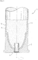
- Figure 1 schematically shows an embodiment of a sleeve 6 according to the invention as part of a cartridge 1.
- the sleeve is elongated and cylindrical and takes up the granular propellant powder 4 in its interior.
- An insert 5 is embedded in the jacket wall of the sleeve 6.
- a base 2 made of brass with an igniter 3 is attached.
- the sleeve 6 is made of felted pulp and nitrocellulose fibers and conventional additives.
- the embedded insert 5 is an expandable tube that was seamlessly made from a knitted fabric 12, here, for example, a knitted, crocheted and / or knitted fabric. Due to its shown embedding in the sleeve 6, its central axis coincides with the central axis of the sleeve.
- the hose is made from 50 percent normal cotton yarn and 50 percent from a polyurethane-cotton blend yarn, although a variant with one third cotton yarn and two thirds polyurethane-cotton blend yarn has also proven to be a good material for the tubing.
- the mixed yarn has a core made of polyurethane, which is covered with the cotton.
- the blended yarn has a composition of 89% cotton and 11% PUR, with a PU content between 5% and 20% being possible in different versions.
- the tube forming the insert is extremely stretchable.
- the stretchability in the axial direction of the sleeve is additionally supported by the polyurethane-cotton blended yarn.
- the insert is exposed in the fracture opening and stretched there so far that it breaks the fracture opening relative to the granular propellant powder inside the Keeps the sleeve closed.
- a typical sleeve according to the invention has an outer diameter between 50 and 170 mm and a length between 35 and 75 cm, a jacket wall thickness of 1.5 mm to 4 mm, in particular of 2.5 mm.
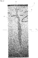
- Figure 2 shows a photo of a pod Fig. 1 after a break test with an insert 5 partially exposed at a fracture area 8, the arrangement of the insert 5 between a radially inner part 6a and a radially outer part 6b of the sleeve 6 can be clearly seen. In some cases there is also a matting formed by the mesh of the insert 5 10 recognizable.
- the dark lettering on the outer part 6b of the sleeve 6 originates from the sample identification of the fracture test carried out and is irrelevant in the present case.
- Fig. 3 shows schematically a section of the knitted fabric 12, which the tube of the insert 5 of the sleeve 6 from the Fig. 1 and 2nd trains.
- the insert 5 as knitted fabric 12, in particular as knitted, crocheted and / or knitted fabric, provides very good strengths and high elongation values with a relatively low basis weight and a low radial dimension of the tube.
- Such textile surfaces are produced, for example, on circular knitting machines.
- a circular knitting machine can be used, for example, to produce a seamless tubular insert as in the exemplary embodiment shown.
- a specific stitch weave 14 is used in the exemplary embodiment.
- a weave image 16 of this stitch weave 14 is from the Fig. 3 evident.
- the weave image 16 shows a section of a large number of stitch rows 18 which are in the vertical direction of the representation of the Fig. 3 are arranged one above the other, and a plurality of wales 20 in the transverse direction of the illustration of the Fig. 3 are arranged side by side.
- the vertical direction corresponds to that of FIG Fig. 3 a longitudinal direction L of the insert 5 or the sleeve 6; the transverse direction corresponds to the circumferential direction U of the insert 5 or the sleeve 6.
- Each stitch 20.2 is passed at its lower end through the corresponding stitch 20.3 of the row 18.3 adjacent to the bottom and in turn guides the corresponding stitch 20.1 of the row 18.1 adjacent to the top.
- the assigned stitches 20 of the adjoining stitch rows 18 form a wale 23 and are each guided on the same radial side of the tube of the insert; d. H. either all on the outside or all on the inside.
- Adjacent stitches 20 of a course 18 are in principle guided on the other radial side; d. H. if the one adjacent stitch 20 is guided on the inside, the adjacent stitches 19 and 21 are each guided on the outside, and if the one adjacent stitch leads on the inside, the adjacent stitches each lead on the inside.
- the insert has a fabric image with between 20 (twenty) and 26
- the insert has a fabric image with between 21 (twenty-one) and 27 (twenty-seven) wales per two centimeters, especially between 23.5 and 24.5 wales per two Centimeter.
- the insert in the exemplary embodiment has a fabric stretch, in particular in the circumferential direction U (or radial direction R) of the sleeve and / or in the longitudinal direction L of the sleeve, of 5% to 20% compared to the unstretched state, in particular of approximately 11%.
- This state of expansion is at least in terms of the order of magnitude Fig. 2 elongation state shown if the slight additional elongation due to the displacement at the breaking point remains neglected.
- the seamless tubular insert 5 used in the exemplary embodiment has a maximum elongation of approximately 420% in the transverse direction of the illustration - that is to say in the circumferential direction U of the hose.
- the maximum elongation is approximately 80%.
- a maximum elongation in the radial direction of the tube of the insert 5 can be calculated from or with the tube diameter in the unstretched state and the maximum elongation in the circumferential direction U of the tube, if necessary taking into account an additional elongation in the longitudinal direction L.
- cellulosic fibers are suitable which are sorted (100% cellulosic fibers) or in a fiber mixture (for example cotton fibers with a synthetic material such as PUR).
- the desired felting quality of the sleeve (when felting through the insert) is achieved, i.e. it is ensured that the fiber mass raked in the "mesh legs" of the textile and thus prevents separation or splitting of the sleeve body.
Landscapes
- Engineering & Computer Science (AREA)
- General Engineering & Computer Science (AREA)
- Textile Engineering (AREA)
- Manufacturing & Machinery (AREA)
- Knitting Of Fabric (AREA)
- Woven Fabrics (AREA)
- Manufacturing Of Micro-Capsules (AREA)
- Medicinal Preparation (AREA)
- Cosmetics (AREA)
Abstract
Description
- Die Erfindung betrifft eine verbrennbare, zylindrische Hülse zur Aufnahme von Treibladungspulver mit einer formstabilen Mantelwand aus verbrennbarem verfilzten Fasermaterial und einer Einlage aus einem textilen Flächengebilde, das in der Mantelwand eingebettet ist. Ferner betrifft die Erfindung ein Verfahren zur Herstellung einer solchen zylindrischen Hülse.
- Hülsen sind als Bestandteil von Munition für Schusswaffen seit langem bekannt. Sie dienen zur Aufnahme des Treibladungspulvers, das in der Regel in körniger Form vorliegt. Üblicherweise haben Hülsen eine kreiszylindrische und längliche Hohlform; die Zylinderwand der Hülse wird hier als Mantelwand bezeichnet.
- Verbrennbare Hülsen verbrennen bzw. verzehren sich als Folge des Abfeuerns. Geschieht dies hinreichend rückstandsfrei, brauchen keine Hülsenreste vor dem nächsten Schuss entfernt zu werden. Idealerweise ist nur noch ein außen, an die Hülse angesetzter Boden aus Metall auszuwerfen.
- Es ist bekannt, verbrennbare Hülsen aus Nitrozellulose und Zellstoff herzustellen, in der Regel mit Additiven wie Bindeharz und Stabilisatoren. Zur Herstellung wird eine Siebform vertikal oder horizontal in eine wässrige Pülpe mit Nitrozellulose und Zellstoff getaucht. Mit Hilfe von Unterdruck saugt die Siebform den Faserbrei an. Es bildet sich ein nasses Vlies aus, üblicherweise "Rohfilz" genannt, das die Vorstufe der Mantelwand darstellt. Das Vlies bzw. der Rohfilz wird zum Erzielen der endgültigen Geometrie der Mantelwand und zum Entwässern noch verpresst und zumindest zeitweise auch erhitzt, wodurch die Hülse formstabil wird.
- Gleichwohl ist die Hülse aufgrund der Natur des verbrennbaren Materials bruchempfindlich. Fällt sie zu Boden oder stößt sie bei der Handhabung an einem festen Gegenstand, kann Rissbildung in der Mantelwand oder vollständiges Zerbrechen der Hülse die Folge sein. Ist die Hülse bestimmungsgemäß mit Treibladungspulver gefüllt, ist dies nicht mehr tolerierbar, da austretendes Treibladungspulver offensichtlich ein enormes Sicherheitsrisiko darstellt.
- Aus diesem Grund gibt es schon lange verschiedene Vorschläge, die Mantelwand der Hülse durch eine eingebettete Einlage zu verstärken und so die Bruchempfindlichkeit herabzusetzen. So ist z. B. aus der
WO 2011/015346 A1 bekannt, in die bei der Herstellung der Pülpe entstehende Mantelwand ein grobmaschiges Netz aus Baumwollgarn einzuwickeln. Das mehrlagig eingewickelte Netz erhöht die Festigkeit der Hülse so ausreichend, dass Rissbildung in der Mantelwand oder gar vollständiges Zerbrechen der Hülse durch Anstoßen oder Herunterfallen praktisch ausgeschlossen ist. Allerdings ist das Herstellungsverfahren aufwendig und die Dicke der Mantelwand ist hoch, was - bei vorgegebenem Außendurchmesser - das nutzbare Volumen der Hülse für die Aufnahme von Treibladungspulver kleiner macht, als es ohne mehrlagige Verstärkungs-Einlage möglich wäre. - Es besteht also Bedarf für eine Hülse, die sicher in der Handhabung ist und trotzdem mit einer vergleichsweise dünnen Mantelwand auskommt.
- Dementsprechend wird erfindungsgemäß eine verbrennbare Hülse zur Aufnahme von Treibladungspulver mit den Merkmalen des unabhängigen Anspruchs 1 vorgeschlagen. Ferner wird ein Verfahren zur Herstellung einer zylindrischen Hülse mit den Merkmalen des Anspruchs 9 vorgeschlagen. Vorteilhafte Ausgestaltungen sind Gegenstand der Unteransprüche sowie der nachfolgenden Beschreibung.
- Die Erfindung umfasst die Einbettung einer Einlage, die dehnbar ist, in der Mantelwand der Hülse. Das steht im Gegensatz zur bisherigen Tradition, durch die Einlage die Festigkeit der Mantelwand zu erhöhen. Bei der Erfindung wird die mechanische Beschädigung der Mantelwand zugelassen und die Einlage hat nun die Funktion, etwa entstehende Risse und Bruchöffnungen in der Mantelwand gegenüber dem Austritt von Treibladungspulver verschlossen zu halten, wozu sie auf Grund ihrer Dehnbarkeit in der Lage ist. Das ermöglicht eine geringe Dicke der Mantelwandhülse auf zweierlei Weise. Die mechanische Festigkeit, die die Mantelwand von vorneherein ohne Berücksichtigung einer Einlage hat, kann geringer als bisher angesetzt werden, da Risse und Brüche zulässig sind. Und die Einlage selbst kann ebenfalls vergleichsweise dünn sein, da sie die Mantelwand nicht verstärken, sondern nur das Schüttpulver im Inneren der Hülse zurückhalten soll.
- Die Dehnbarkeit der Einlage ist so zu bemessen, dass sie diese Funktion, also das Überbrücken von Rissen und anderen Bruchöffnungen durch Ausdehnung erfüllen kann, ohne ihre Bruchdehnung zu erreichen. Die in diesem Sinne richtigen Dehnungsparameter können empirisch ermittelt werden, z. B. durch standardisierte Falltests, die bisher zur Prüfung der Bruchfestigkeit der bekannten Hülsen eingesetzt wurden. Von der Anmelderin mit erfindungsgemäßen Hülsen bereits durchgeführte Tests haben gezeigt, dass der ausreichenden Dehnbarkeit der Einlage in Längsrichtung der Hülse eine größere Bedeutung als der Dehnbarkeit in Umfangsrichtung zukommt.
- Bevorzugt wird die Dehnbarkeit der Einlage durch eine Ausbildung derselben als Maschenware und ganz bevorzugt als Wirkware, Strickware und/oder Häkelware erreicht. Hier ist die Dehnbarkeit das Ergebnis der Fadenführung.
- Weil die Einlage selbstverständlich ebenfalls verbrennbar sein muss, besteht diese normalerweise aus Baumwollgarn. Dies ist allerdings selber nicht dehnbar. Soll auch das Garn zur Dehnbarkeit beitragen, wird Baumwollgarn ganz oder teilweise durch ein Polyurethan-Baumwoll-Mischgarn ersetzt. Solches Mischgarn ist kommerziell verfügbar. Es hat regelmäßig einen Kern aus Polyurethan, der von Baumwolle ummantelt ist.
- Im Interesse, die Dicke der Mantelwand klein zu halten, wird eine Einlage bevorzugt, die aus nur einer Lage der Maschenware besteht. Es hat sich gezeigt, dass die einlagige Ausbildung ausreicht, das Austreten von Schüttpulver durch Bruchspalten und andere Bruchöffnungen in der Mantelwand sicher zu verhindern.
- Gestützt auf empirisch gewonnene Erkenntnisse, ist die Anordnung der Einlage, bezogen auf die Wanddicke der Mantelwand, in deren Mitte optimal. Aber auch eine Anordnung im weiter innenliegenden Wandbereich ist ohne signifikante Beeinträchtigung der Rückhalte-Funktion möglich. Eine solche Anordnung kann durch die Herstellung bedingt sein.
- Bei der für alle Formen der Einlage bevorzugten Ausführungsform ist die Einlage als dehnbarer Schlauch ausgebildet, dessen Mittelachse im eingebetteten Zustand mit der Mittelachse der Hülse zusammenfällt. Der Schlauch ist vorzugsweise nahtlos gefertigt. Geeignete dehnbare Schläuche werden als Maschenware, insbesondere als Wirkware, Häkelware und/oder Strickware industriell hergestellt und sind kommerziell erhältlich.
- Die Verwendung schlauchförmiger Einlagen vereinfacht die Herstellung erfindungsgemäßer Hülsen enorm. Im Zuge des Eingangs geschilderten Herstellungsverfahrens wird nach Aufbau des Rohfilzes bis zu einer beispielsweise mittleren Wanddicke der dehnbare Einlagen-Schlauch aufgeweitet und in Achsrichtung der Siebform über den bis dahin aufgebauten Rohfilz gezogen. Anschließend wird der Rohfilz bis zum Erreichen der endgültigen Dicke weiter aufgebaut und dann, wie sonst auch, verpresst und durch Erhitzen ausgehärtet.
- Um eine radial möglichst dünne Einlage zu erreichen und damit bei einem vorgegebenen Durchmesser mehr Platz für Treibladungspulver zu haben, ist gemäß einer Ausführung die Einlage einlagig ausgebildet und sowohl axial als auch radial dehnbar. Bei einer Einlageausführung muss das textile Flächengebilde zum Abfangen von Rissen/Brüchen etc. der Hülse 2-achsig dehnbar sein und damit eine axiale und eine radiale Dehnung ermöglichen.
- Gemäß einer anderen Ausführung weist die Einlage wenigstens zwei oder drei Lagen auf, von denen eine erste Lage zumindest axial dehnbar und eine zweite Lage zumindest radial dehnbar ist. Damit können günstigere textile Flächengebilde verwendet werden, die jeweils nur hinsichtlich einer Achse dehnbar sein müssen.
- Unter einer radialen Dehnbarkeit der Einlage ist vorliegend insbesondere eine Dehnbarkeit der Einlage bzgl. einer Umfangsrichtung der Einlage zu verstehen, insbesondere wenn die Einlage eine Schlauchform oder eine andere, insbesondere zylindrische oder teilzylindrische, Hohlform aufweist. Die Entsprechung der beiden Begriffe ergibt sich insbesondere aus der Anwendung einer schlauchförmigen Einlage: wird der der Schlauch radial gedehnt, wird insbesondere diese Dehnbarkeit durch eine Dehnung der Einlage bzgl. ihrer Umfangsrichtung bereitgestellt.
- Je nach verwendetem Material und gegebenenfalls je nach Verarbeitung des Materials zu einer geeigneten Maschenware ist die Einlage gemäß unterschiedlichen Ausführungen aufgrund einer makroskopischen Elastizität eines Materials der Einlage und/oder aufgrund einer Vermaschung einer Maschenware der Einlage dehnbar.
- Hinsichtlich der Materialwahl für die Einlage haben Versuche ergeben, dass die Einlage sinnvollerweise wenigstens einen Natur- und/oder Kunststoffgarn, insbesondere einen Baumwollgarn und/oder Polyurethan-Baumwoll-Mischgarn und/oder Seidengarn und/oder Polyurethan-Garn und /oder Nylongarn, aufweist, insbesondere aus wenigstens einem solchen besteht.
- Gemäß einer Ausführung ist die Einlage, bezogen auf die Dicke der Mantelwand, in deren Mitte oder näher an einer Innenseite oder einer Außenseite der Mantelwand angeordnet, wobei insbesondere eine Anordnung der Einlage zwischen dem ersten Viertel und dem vierten Viertel der Dicke der Mantelwand vorgesehen ist. Versuche der Anmelderin haben ergeben, dass eine Anordnung der Einlage zwischen dem ersten und dem zweiten Drittel der Dicke der Mantelwand im Schadensfall einen Rückhalt des Treibladungspulvers sicherstellt; ebenso gelingt dies auch bei mittiger Anordnung und bei einer Anordnung zwischen dem zweiten und dem dritten Drittel der Dicke der Mantelwand.
- Um den Fertigungsprozess weiter zu vereinfachen, kann gemäß einer Ausführung die Einlage auch direkt an einer Innenseite der Mantelwand angeordnet sein. Dann muss das Verfilzen der Hülse am Sieb nicht unterbrochen werden, um die Einlage aufzuziehen. Vielmehr wird die Einlage zuerst aufgezogen und anschließend mit der Verfilzung begonnen. Bei dieser Herstellungsvariante lagert sich insbesondere zwischen den Maschen der Einlage Hülsenmaterial ab, sodass die Einlage zuverlässig und fest an der fertigen Hülse angeordnet ist.
- Unter einer zylindrischen Hülse ist vorliegend auch eine Hülse zu verstehen, die zwar im wesentlichen Teil ihrer Längserstreckung kreiszylindrisch ausgebildet ist, jedoch zu ihrem Boden und/oder ihrer Spitze hin einen abweichenden, insbesondere sich verjüngenden Durchmesser aufweist.
- Gemäß einem Aspekt der Erfindung wird ein Verfahren zur Herstellung einer zylindrischen Hülse, insbesondere nach einer Ausführung der Erfindung, vorgeschlagen. Das Verfahren weist zumindest die folgenden Schritte auf: Tauchen einer Siebform in eine wässrige Pülpe mit Nitrozellulose und Zellstoff; Ansaugen der Pülpe an die Siebform mit Hilfe von Unterdruck, sodass sich ein Vlies ausbildet; Aufziehen einer schlauchförmigen Einlage auf die Siebform und/oder auf das bis dahin ausgebildete Vlies.
- Gemäß einer Ausführung erfolgt das Aufziehen der Einlage vor dem Ansaugen der Pülpe oder als Zwischenschritt zwischen zwei Ansaugvorgängen oder während des Ansaugens der Pülpe.
- Wenn das Aufziehen der Einlage vor dem Ansaugen der Pülpe erfolgt, ist die Einlage bei der fertigen Hülse an der Innenseite der Mantelwand angeordnet. Wenn das Aufziehen der Einlage als Zwischenschritt zwischen zwei Ansaugvorgängen und/oder während des Ansaugens der Pülpe erfolgt, kann durch die Auswahl eines Zeitpunkts des Aufziehens der Einlage festgelegt werden, in welchem Bereich der Dicke der Mantelwand die Einlage in der fertigen Hülse angeordnet ist.
- Beispielsweise kann durch Versuche ermittelt werden, wie lange vor dem Aufziehen der Einlage einerseits und nach dem Aufziehen der Einlage andererseits Pülpe angesaugt werden muss, um eine radial mittige Anordnung der Einlage bezüglich der Dicke der Mantelwand zu erreichen.
- Weitere Vorteile und Anwendungsmöglichkeiten der Erfindung ergeben sich aus der nachfolgenden Beschreibung im Zusammenhang mit den Figuren.
- Fig. 1
- zeigt schematisch eine Hülse nach einer beispielhaften Ausführung der Erfindung als Bestandteil einer Kartusche.
- Fig. 2
- zeigt ein Foto einer Hülse aus
Fig. 1 nach einem Bruchtest mit an dem Bruchbereich teilweise freigelegter Einlage. - Fig. 3
- zeigt schematisch einen Ausschnitt aus der Maschenware, die die Einlage der Hülse aus den
Fig. 1 und2 ausbildet. -
Figur 1 zeigt als Ausführungsbeispiel schematisch eine erfindungsgemäße Hülse 6 als Bestandteil einer Kartusche 1. Die Hülse ist länglich und kreiszylindrisch und nimmt in ihrem Inneren das körnige Treibladungspulver 4 auf. In der Mantelwand der Hülse 6 ist eine Einlage 5 eingebettet. - Am unteren Ende der Kartusche 1 ist ein Boden 2 aus Messing mit einem Zünder 3 angebracht.
- Die Hülse 6 ist aus verfilztem Zellstoff und Nitrozellulosefasern sowie herkömmlichen Additiven hergestellt. Bei der eingebetteten Einlage 5 handelt es sich um einen dehnbaren Schlauch, der aus einer Maschenware 12, hier beispielhaft einer Wirk-, Häkel- und/oder Strickware, nahtlos gefertigt wurde. Aufgrund seiner gezeigten Einbettung in die Hülse 6 fällt seine Mittelachse mit der Mittelachse der Hülse zusammen.
- Der Schlauch ist zu 50 Prozent aus normalem Baumwollgarn und zu 50 Prozent aus einem Polyurethan-Baumwoll-Mischgarn hergestellt, wobei sich bei Versuchen auch eine Variante mit einem Drittel Baumwollgarn und zwei Dritteln Polyurethan-Baumwoll-Mischgarn als gutes Material für den Schlauch herausgestellt hat. In beiden Fällen hat das Mischgarn einen Kern aus Polyurethan, der mit der Baumwolle ummantelt ist. Im Ausführungsbeispiel weist das Mischgarn einer Zusammensetzung von 89% Baumwolle und 11% PUR auf, wobei in unterschiedlichen Ausführungen ein PUR-Anteil zwischen 5% und 20% infrage kommen kann.
- Aufgrund seiner Ausbildung als Maschenware 12 ist der die Einlage bildende Schlauch stark dehnbar. Die Dehnbarkeit in Achsrichtung der Hülse wird durch das Polyurethan-Baumwoll-Mischgarn zusätzlich unterstützt.
- Wird die Hülse 6 durch mechanische Einwirkung beschädigt, sodass ein Riss, ein Spalt oder eine andere Bruchöffnung in der Mantelwand entsteht, wird die Einlage in der Bruchöffnung freigelegt und dort soweit gedehnt, dass sie ohne zu reißen die Bruchöffnung gegenüber dem körnigen Treibladungspulver im Inneren der Hülse verschlossen hält.
- Eine typische Hülse nach der Erfindung hat bei einem Außendurchmesser zwischen 50 und 170 mm und einer Länge zwischen 35 und 75 cm eine Mantelwand-Dicke von 1,5 mm bis 4 mm, insbesondere von 2,5 mm.
-
Figur 2 zeigt ein Foto einer Hülse ausFig. 1 nach einem Bruchtest mit an einem Bruchbereich 8 teilweise freigelegter Einlage 5. Gut erkennbar ist dabei die Anordnung der Einlage 5 zwischen einem radial inneren Teil 6a und einem radial äußeren Teil 6b der Hülse 6. Teilweise ist auch eine durch die Maschen der Einlage 5 ausgebildete Verfilzung 10 erkennbar. - Die dunkle Beschriftung auf dem äußeren Teil 6b der Hülse 6 entstammt der Probenkennzeichnung des durchgeführten Bruchtests und ist vorliegend irrelevant.
-
Fig. 3 zeigt schematisch einen Ausschnitt aus der Maschenware 12, die den Schlauch der Einlage 5 der Hülse 6 aus denFig. 1 und2 ausbildet. - Versuche der Anmelderin haben ergeben, dass die Einlage 5 als Maschenware 12, insbesondere als Wirk-, Häkel- und/oder Strickware, sehr gut hohe Festigkeiten und große Dehnwerte bei relativ geringem Flächengewicht und einem niedrigen Radialmaß des Schlauchs bereitstellt. Solche textilen Flächen werden beispielsweise auf Rundstrickmaschinen hergestellt. Mit einer Rundstrickmaschine kann beispielsweise eine nahtlose schlauchartige Einlage wie im dargestellten Ausführungsbeispiel hergestellt werden.
- Um sehr hohe Dehnungen der Einlage 5 zu ermöglichen, wird im Ausführungsbeispiel eine bestimmte Maschenbindung 14 verwendet. Ein Bindungsbild 16 dieser Maschenbindung 14 ist aus der
Fig. 3 ersichtlich. - Das Bindungsbild 16 zeigt ausschnittsweise eine Vielzahl von Maschenreihen 18, die in Hochrichtung der Darstellung der
Fig. 3 übereinander angeordnet sind, und eine Vielzahl von Maschenstäbchen 20, die in Querrichtung der Darstellung derFig. 3 nebeneinander angeordnet sind. Im Ausführungsbeispiel entspricht die Hochrichtung der Darstellung derFig. 3 einer Längsrichtung L der Einlage 5 bzw. der Hülse 6; die Querrichtung entspricht der Umfangsrichtung U der Einlage 5 bzw. der Hülse 6. - Jede Masche 20.2 ist an ihrem unteren Ende durch die entsprechende Masche 20.3 der unten angrenzenden Maschenreihe 18.3 hindurchgeführt und führt ihrerseits die entsprechende Masche 20.1 der oben angrenzenden Maschenreihe 18.1.
- Die einander zugeordneten Maschen 20 der aneinander angrenzenden Maschenreihen 18 bilden ein Maschenstäbchen 23 und sind jeweils auf der gleichen Radialseite des Schlauchs der Einlage geführt; d. h. entweder alle auf der Außenseite oder alle auf der Innenseite.
- Benachbarte Maschen 20 einer Maschenreihe 18 sind grundsätzlich auf der jeweils anderen Radialseite geführt; d. h. wenn die eine benachbarte Masche 20 auf der Innenseite geführt ist, sind die benachbarten Maschen 19 und 21 jeweils auf der Außenseite geführt, und wenn die eine benachbarte Masche auf der Innenseite führt, führen die benachbarten Maschen jeweils auf der Innenseite.
- Bei der beispielhaften Ausführung der Hülse sind im ungedehnten Zustand der Einlage im Maschenwerk zwischen zehn und 13 (dreizehn) Maschenreihen pro Zentimeter Längserstreckung vorgesehen (Maschenreihenzahl MRZ, in
Figur 3 ist deren Kehrwert eingezeichnet), insbesondere zwischen 11,5 und 12 Maschenreihen. Fachüblich ist auch die Angabe in Maschenreihen pro zwei Zentimeter: in diesem Maß weist die Einlage ein Gewebebild auf mit zwischen 20 (zwanzig) und 26 - (sechsundzwanzig) Maschenreihen pro zwei Zentimeter Längserstreckung auf, insbesondere zwischen 23 und 24 Maschenreihen pro zwei Zentimeter.
- Hinsichtlich der Maschenstäbchen 23 sind im ungedehnten Zustand der Einlage im Gewebebild zwischen zehneinhalb und 13,5 (dreizehn komma fünf) Maschenstäbchen pro Zentimeter Umfangserstreckung vorgesehen (Maschenstäbchenzahl MSZ, in
Figur 3 ist deren Kehrwert eingezeichnet), insbesondere zwischen 11,75 und 12,25 Maschenstäbchen. Fachüblich ist auch die Angabe in Maschenstäbchen pro zwei Zentimeter: in diesem Maß weist die Einlage ein Gewebebild auf mit zwischen 21 (einundzwanzig) und 27 (siebenundzwanzig) Maschenstäbchen pro zwei Zentimeter Umfangserstreckung auf, insbesondere zwischen 23,5 und 24,5 Maschenstäbchen pro zwei Zentimeter. - In einem auf die Hülse aufgezogenen Zustand weist die Einlage im Ausführungsbeispiel eine Gewebedehnung, insbesondere in Umfangsrichtung U (bzw. Radialrichtung R) der Hülse und/oder in Längsrichtung L der Hülse, von 5% bis 20% im Vergleich zum ungedehnten Zustand auf, insbesondere von ca. 11%. Dieser Dehnungszustand ist zumindest hinsichtlich der Größenordnung auch der in
Fig. 2 dargestellte Dehnungszustand, wenn die leichte zusätzliche Dehnung durch die Verschiebung an der Bruchstelle vernachlässigt bleibt. - Die im Ausführungsbeispiel verwendete nahtlose schlauchförmige Einlage 5 weist in Querrichtung der Darstellung - also in Umfangsrichtung U des Schlauchs - eine maximale Dehnung von ca. 420 % auf. In Hochrichtung der Darstellung - also in Längsrichtung L des Schlauchs - beträgt die maximale Dehnung ca. 80 %. Eine maximale Dehnung in Radialrichtung des Schlauchs der Einlage 5 kann aus oder mit dem Schlauchdurchmesser im ungedehnten Zustand und der maximalen Dehnung in Umfangsrichtung U des Schlauchs berechnet werden, ggf. unter Berücksichtigung einer zusätzlichen Dehnung in Längsrichtung L.
- Für das Material der Einlage 5 eignen sich beispielsweise zellulosische Fasern, die sortenrein (100% zellulosische Fasern) oder in Fasermischung (beispielsweise Baumwollfasern mit einem synthetischen Material wie beispielsweise PUR) verwendet werden.
- Durch die (an sich fachmännische) Abstimmung der Faserstärken und der technologischen Parameter der Garn- und Strickproduktion wird ausgehend von der beispielhaften Ausführung die gewünschte Filzungsqualität der Hülse (bei der Verfilzung durch die Einlage hindurch) erzielt, d.h. es wird sichergestellt, dass sich die Fasermasse in den "Maschenschenkeln" des Textiles verharkt und damit eine Trennung, bzw. Aufsplittung des Hülsenkörpers verhindert.
-
- 1
- Kartusche
- 2
- Boden
- 3
- Zünder
- 4
- Treibladungspulver
- 5
- Einlage
- 6
- Hülse
- 6a
- innerer Teil der Hülse
- 6b
- äußerer Teil der Hülse
- 8
- Bruchbereich
- 10
- Verfilzung
- 12
- Maschenware
- 14
- Maschenbindung
- 16
- Bindungsbild
- 18
- Maschenreihe
- 19, 20, 21
- Masche
- 23
- Maschenstäbchen
- L
- Längsachse/-richtung
- U
- Umfangsrichtung
- R
- Radialrichtung
- MRZ
- Maschenreihenzahl
- MSZ
- Maschenstäbchenzahl
Claims (10)
- Zylindrische Hülse (6) zur Aufnahme von Treibladungspulver (4) mit einer formstabilen Mantelwand aus verbrennbarem, verfilztem Fasermaterial und einer Einlage (5) aus einem textilen Flächengebilde in der Mantelwand,
dadurch gekennzeichnet,
dass die Einlage (5) dehnbar ist. - Hülse nach Anspruch 1, bei welcher die Einlage (5) einlagig ausgebildet und sowohl axial als auch radial dehnbar ist.
- Hülse nach Anspruch 1, bei welcher die Einlage (5) wenigstens zwei oder drei Lagen aufweist, von denen eine erste Lage zumindest axial dehnbar und eine zweite Lage zumindest radial dehnbar ist.
- Hülse nach einem der vorhergehenden Ansprüche, bei welcher die Einlage (5) aus Maschenware, insbesondere Wirkware, besteht.
- Hülse nach einem der vorhergehenden Ansprüche, bei welcher die Einlage (5), bezogen auf die Dicke der Mantelwand, in deren Mitte oder näher an einer Innenseite oder einer Außenseite der Mantelwand angeordnet ist, wobei insbesondere eine Anordnung der Einlage zwischen dem ersten Viertel und dem vierten Viertel der Dicke der Mantelwand vorgesehen ist.
- Hülse nach einem der Ansprüche 1 bis 4, bei welcher die Einlage (5) an einer Innenseite der Mantelwand angeordnet ist.
- Hülse nach einem der vorhergehenden Ansprüche, bei welcher die Einlage (5) als Schlauch ausgebildet ist, dessen Mittelachse mit der Mittelachse der Hülse (6) zusammenfällt.
- Hülse nach Anspruch 7, bei welcher der Schlauch nahtlos gefertigt ist.
- Verfahren zur Herstellung einer zylindrischen Hülse (6) gemäß einem der vorherigen Ansprüche, aufweisend die Schritte:- Tauchen einer Siebform in eine wässrige Pülpe mit Nitrozellulose und Zellstoff,- Ansaugen der Pülpe an die Siebform mit Hilfe von Unterdruck, sodass sich ein Vlies ausbildet,- Aufziehen einer schlauchförmigen Einlage auf die Siebform und/oder auf das bis dahin ausgebildete Vlies.
- Verfahren gemäß Anspruch 9, wobei das Aufziehen der Einlage vor dem Ansaugen der Pülpe oder als Zwischenschritt zwischen zwei Ansaugvorgängen oder während des Ansaugens der Pülpe erfolgt.
Priority Applications (2)
| Application Number | Priority Date | Filing Date | Title |
|---|---|---|---|
| RS20230131A RS64005B1 (sr) | 2018-10-04 | 2019-10-04 | Cilindrična čaura za bezdimni barut |
| HRP20230193TT HRP20230193T1 (hr) | 2018-10-04 | 2019-10-04 | Cilindrična čahura za punjenje potisnim prahom |
Applications Claiming Priority (2)
| Application Number | Priority Date | Filing Date | Title |
|---|---|---|---|
| DE102018007834 | 2018-10-04 | ||
| DE102018218423.2A DE102018218423A1 (de) | 2018-10-29 | 2018-10-29 | Zylindrische Hülse für Treibladungspulver |
Publications (2)
| Publication Number | Publication Date |
|---|---|
| EP3643826A1 true EP3643826A1 (de) | 2020-04-29 |
| EP3643826B1 EP3643826B1 (de) | 2022-11-30 |
Family
ID=68158984
Family Applications (1)
| Application Number | Title | Priority Date | Filing Date |
|---|---|---|---|
| EP19201561.8A Active EP3643826B1 (de) | 2018-10-04 | 2019-10-04 | Zylindrische hülse für treibladungspulver |
Country Status (13)
| Country | Link |
|---|---|
| US (1) | US11118874B2 (de) |
| EP (1) | EP3643826B1 (de) |
| JP (1) | JP7441626B2 (de) |
| KR (1) | KR102675062B1 (de) |
| CA (1) | CA3057648C (de) |
| DK (1) | DK3643826T3 (de) |
| ES (1) | ES2938922T3 (de) |
| FI (1) | FI3643826T3 (de) |
| HR (1) | HRP20230193T1 (de) |
| HU (1) | HUE061225T2 (de) |
| LT (1) | LT3643826T (de) |
| PL (1) | PL3643826T3 (de) |
| RS (1) | RS64005B1 (de) |
Cited By (1)
| Publication number | Priority date | Publication date | Assignee | Title |
|---|---|---|---|---|
| EP3800287A1 (de) * | 2019-10-04 | 2021-04-07 | Nitrochemie Aschau GmbH | Aus textilem gewebe hergestellter einsatz |
Families Citing this family (1)
| Publication number | Priority date | Publication date | Assignee | Title |
|---|---|---|---|---|
| DE102020001052A1 (de) * | 2020-02-19 | 2021-08-19 | Nitrochemie Aschau Gmbh | Hülsenmantel |
Citations (7)
| Publication number | Priority date | Publication date | Assignee | Title |
|---|---|---|---|---|
| US3218907A (en) * | 1963-10-23 | 1965-11-23 | Keith F Beal | Felting process for making combustible cartridge cases |
| US3474702A (en) * | 1965-12-16 | 1969-10-28 | Us Army | Felting process for making combustible cartridge cases |
| US3769873A (en) * | 1972-01-25 | 1973-11-06 | Us Army | Process for uniformly depositing resin in combustible cartridge cases |
| DE3008999A1 (de) * | 1974-06-14 | 1981-09-24 | Wilhelm Dipl.-Chem. Dr. 5400 Koblenz Oversohl | Verfahren zur herstellung von verbrennbaren munitionsformteilen und vorrichtung zum ausueben des verfahrens |
| DE3008996A1 (de) * | 1980-03-08 | 1981-09-24 | Wilhelm Dipl.-Chem. Dr. 5400 Koblenz Oversohl | Verfahren zur herstellung von verbrennbaren munitionsformteilen, wie kartuschhuelsen oder treibladungsbehaelter mit verstaerkenden gewebeeinlagen und vorrichtung zum ausueben des verfahrens |
| US5243914A (en) * | 1985-10-01 | 1993-09-14 | Dynamit Nobel Aktiengesellschaft | Caseless ammunition |
| WO2011015346A1 (de) | 2009-08-04 | 2011-02-10 | Nitrochemie Aschau Gmbh | Hülse zur aufnahme von treibladungspulver |
Family Cites Families (3)
| Publication number | Priority date | Publication date | Assignee | Title |
|---|---|---|---|---|
| US3397637A (en) * | 1967-02-08 | 1968-08-20 | Army Usa | Combustible and consumable cartridge cases |
| DE19849824A1 (de) * | 1998-10-29 | 2000-05-04 | Dynamit Nobel Ag | Munition mit einer Hülse, deren Wand aus einem verbrennbaren oder verzehrbaren Wickelkörper besteht |
| DE10038751A1 (de) * | 2000-05-26 | 2001-11-29 | Dynamit Nobel Ag | Wickelkörper als Hülse für Munition |
-
2019
- 2019-10-04 RS RS20230131A patent/RS64005B1/sr unknown
- 2019-10-04 EP EP19201561.8A patent/EP3643826B1/de active Active
- 2019-10-04 US US16/593,594 patent/US11118874B2/en active Active
- 2019-10-04 HR HRP20230193TT patent/HRP20230193T1/hr unknown
- 2019-10-04 KR KR1020190123060A patent/KR102675062B1/ko active Active
- 2019-10-04 DK DK19201561.8T patent/DK3643826T3/da active
- 2019-10-04 CA CA3057648A patent/CA3057648C/en active Active
- 2019-10-04 ES ES19201561T patent/ES2938922T3/es active Active
- 2019-10-04 PL PL19201561.8T patent/PL3643826T3/pl unknown
- 2019-10-04 JP JP2019183515A patent/JP7441626B2/ja active Active
- 2019-10-04 FI FIEP19201561.8T patent/FI3643826T3/fi active
- 2019-10-04 HU HUE19201561A patent/HUE061225T2/hu unknown
- 2019-10-04 LT LTEP19201561.8T patent/LT3643826T/lt unknown
Patent Citations (7)
| Publication number | Priority date | Publication date | Assignee | Title |
|---|---|---|---|---|
| US3218907A (en) * | 1963-10-23 | 1965-11-23 | Keith F Beal | Felting process for making combustible cartridge cases |
| US3474702A (en) * | 1965-12-16 | 1969-10-28 | Us Army | Felting process for making combustible cartridge cases |
| US3769873A (en) * | 1972-01-25 | 1973-11-06 | Us Army | Process for uniformly depositing resin in combustible cartridge cases |
| DE3008999A1 (de) * | 1974-06-14 | 1981-09-24 | Wilhelm Dipl.-Chem. Dr. 5400 Koblenz Oversohl | Verfahren zur herstellung von verbrennbaren munitionsformteilen und vorrichtung zum ausueben des verfahrens |
| DE3008996A1 (de) * | 1980-03-08 | 1981-09-24 | Wilhelm Dipl.-Chem. Dr. 5400 Koblenz Oversohl | Verfahren zur herstellung von verbrennbaren munitionsformteilen, wie kartuschhuelsen oder treibladungsbehaelter mit verstaerkenden gewebeeinlagen und vorrichtung zum ausueben des verfahrens |
| US5243914A (en) * | 1985-10-01 | 1993-09-14 | Dynamit Nobel Aktiengesellschaft | Caseless ammunition |
| WO2011015346A1 (de) | 2009-08-04 | 2011-02-10 | Nitrochemie Aschau Gmbh | Hülse zur aufnahme von treibladungspulver |
Cited By (2)
| Publication number | Priority date | Publication date | Assignee | Title |
|---|---|---|---|---|
| EP3800287A1 (de) * | 2019-10-04 | 2021-04-07 | Nitrochemie Aschau GmbH | Aus textilem gewebe hergestellter einsatz |
| US11879713B2 (en) | 2019-10-04 | 2024-01-23 | Nitrochemie Aschau Gmbh | Insert made of a textile fabric |
Also Published As
| Publication number | Publication date |
|---|---|
| US11118874B2 (en) | 2021-09-14 |
| LT3643826T (lt) | 2023-04-11 |
| HUE061225T2 (hu) | 2023-05-28 |
| CA3057648C (en) | 2026-02-24 |
| PL3643826T3 (pl) | 2023-03-27 |
| CA3057648A1 (en) | 2020-04-04 |
| EP3643826B1 (de) | 2022-11-30 |
| HRP20230193T1 (hr) | 2023-03-31 |
| JP7441626B2 (ja) | 2024-03-01 |
| US20200116461A1 (en) | 2020-04-16 |
| RS64005B1 (sr) | 2023-03-31 |
| KR102675062B1 (ko) | 2024-06-14 |
| JP2020076565A (ja) | 2020-05-21 |
| DK3643826T3 (da) | 2023-02-27 |
| KR20200039595A (ko) | 2020-04-16 |
| FI3643826T3 (fi) | 2023-03-21 |
| ES2938922T3 (es) | 2023-04-17 |
Similar Documents
| Publication | Publication Date | Title |
|---|---|---|
| DE102008042657B4 (de) | Textiles Scharnier für Airbagabdeckungen | |
| DE60113087T2 (de) | Gasbrennermembran | |
| DE1805298C3 (de) | Verfahren und Rundstrickmaschine zum Stricken eines schlauchförmigen WarenstUckes | |
| EP3643826B1 (de) | Zylindrische hülse für treibladungspulver | |
| DE19614476A1 (de) | Luftfeder mit inkonstantem Fadenwinkel und Verfahren zur Herstellung einer solchen Luftfeder | |
| DE102018218423A1 (de) | Zylindrische Hülse für Treibladungspulver | |
| EP2462401B1 (de) | Verbrennbare treibladungshülse | |
| DE202019105499U1 (de) | Einlage aus einem textilen Flächengebilde | |
| EP3027391B1 (de) | Verfahren zur herstellung rohrförmiger faserverbundkörper | |
| AT508899B1 (de) | Verfahren zur herstellung eines löcher aufweisenden gestricks | |
| EP1421228B1 (de) | Bindegarn für glühkörper und dessen verwendung | |
| DE102023116097B4 (de) | Verstärkungstextil eines Faserverbundbauteils | |
| DE874075C (de) | Verfahren zum Herstellen von dicken, mit Kautschuk impraegnierten Geweben | |
| EP3196346A1 (de) | Netzartiges gewirktes elastisches material sowie verfahren zu dessen herstellung | |
| DE1936018A1 (de) | Strumpf und Verfahren zu seiner Herstellung | |
| DE1585447A1 (de) | Herstellung von nahtlos gestricktem,laufmaschensicherem Strumpfgewebe | |
| DE2629857A1 (de) | Drainrohr | |
| DE102008040259A1 (de) | Bespannung für eine Papier-, Karton oder Tissuemaschine | |
| DE202017107081U1 (de) | Besonders dehnbarer Bezugsstoff | |
| DE102012204464A1 (de) | Verstärkungsmodul für eine Papiermaschinenbespannung und Verfahren zu dessen Herstellung | |
| DE2123527A1 (de) | Verfahren zum Schließen der Zehe von Strümpfen, Socken oder dergleichen |
Legal Events
| Date | Code | Title | Description |
|---|---|---|---|
| REG | Reference to a national code |
Ref country code: HR Ref legal event code: TUEP Ref document number: P20230193T Country of ref document: HR |
|
| PUAI | Public reference made under article 153(3) epc to a published international application that has entered the european phase |
Free format text: ORIGINAL CODE: 0009012 |
|
| STAA | Information on the status of an ep patent application or granted ep patent |
Free format text: STATUS: THE APPLICATION HAS BEEN PUBLISHED |
|
| AK | Designated contracting states |
Kind code of ref document: A1 Designated state(s): AL AT BE BG CH CY CZ DE DK EE ES FI FR GB GR HR HU IE IS IT LI LT LU LV MC MK MT NL NO PL PT RO RS SE SI SK SM TR |
|
| AX | Request for extension of the european patent |
Extension state: BA ME |
|
| STAA | Information on the status of an ep patent application or granted ep patent |
Free format text: STATUS: REQUEST FOR EXAMINATION WAS MADE |
|
| 17P | Request for examination filed |
Effective date: 20201023 |
|
| RBV | Designated contracting states (corrected) |
Designated state(s): AL AT BE BG CH CY CZ DE DK EE ES FI FR GB GR HR HU IE IS IT LI LT LU LV MC MK MT NL NO PL PT RO RS SE SI SK SM TR |
|
| STAA | Information on the status of an ep patent application or granted ep patent |
Free format text: STATUS: EXAMINATION IS IN PROGRESS |
|
| RIN1 | Information on inventor provided before grant (corrected) |
Inventor name: HUBER, ALEXANDER Inventor name: OLTMANNS, JENS Inventor name: FOCKEN, ULRICH Inventor name: LEBACHER, WALTER |
|
| 17Q | First examination report despatched |
Effective date: 20210628 |
|
| RIN1 | Information on inventor provided before grant (corrected) |
Inventor name: OLTMANNS, JENS Inventor name: HUBER, ALEXANDER Inventor name: FOCKEN, ULRICH Inventor name: LEBACHER, WALTER |
|
| GRAP | Despatch of communication of intention to grant a patent |
Free format text: ORIGINAL CODE: EPIDOSNIGR1 |
|
| STAA | Information on the status of an ep patent application or granted ep patent |
Free format text: STATUS: GRANT OF PATENT IS INTENDED |
|
| INTG | Intention to grant announced |
Effective date: 20220725 |
|
| GRAS | Grant fee paid |
Free format text: ORIGINAL CODE: EPIDOSNIGR3 |
|
| GRAA | (expected) grant |
Free format text: ORIGINAL CODE: 0009210 |
|
| STAA | Information on the status of an ep patent application or granted ep patent |
Free format text: STATUS: THE PATENT HAS BEEN GRANTED |
|
| AK | Designated contracting states |
Kind code of ref document: B1 Designated state(s): AL AT BE BG CH CY CZ DE DK EE ES FI FR GB GR HR HU IE IS IT LI LT LU LV MC MK MT NL NO PL PT RO RS SE SI SK SM TR |
|
| REG | Reference to a national code |
Ref country code: CH Ref legal event code: EP Ref country code: GB Ref legal event code: FG4D Free format text: NOT ENGLISH |
|
| REG | Reference to a national code |
Ref country code: AT Ref legal event code: REF Ref document number: 1534753 Country of ref document: AT Kind code of ref document: T Effective date: 20221215 Ref country code: DE Ref legal event code: R096 Ref document number: 502019006402 Country of ref document: DE |
|
| REG | Reference to a national code |
Ref country code: IE Ref legal event code: FG4D Free format text: LANGUAGE OF EP DOCUMENT: GERMAN |
|
| REG | Reference to a national code |
Ref country code: DK Ref legal event code: T3 Effective date: 20230224 |
|
| REG | Reference to a national code |
Ref country code: NL Ref legal event code: FP |
|
| REG | Reference to a national code |
Ref country code: NO Ref legal event code: T2 Effective date: 20221130 |
|
| REG | Reference to a national code |
Ref country code: SE Ref legal event code: TRGR |
|
| REG | Reference to a national code |
Ref country code: HR Ref legal event code: T1PR Ref document number: P20230193 Country of ref document: HR |
|
| REG | Reference to a national code |
Ref country code: EE Ref legal event code: FG4A Ref document number: E023112 Country of ref document: EE Effective date: 20230215 Ref country code: ES Ref legal event code: FG2A Ref document number: 2938922 Country of ref document: ES Kind code of ref document: T3 Effective date: 20230417 |
|
| REG | Reference to a national code |
Ref country code: SK Ref legal event code: T3 Ref document number: E 41359 Country of ref document: SK |
|
| PG25 | Lapsed in a contracting state [announced via postgrant information from national office to epo] |
Ref country code: PT Free format text: LAPSE BECAUSE OF FAILURE TO SUBMIT A TRANSLATION OF THE DESCRIPTION OR TO PAY THE FEE WITHIN THE PRESCRIBED TIME-LIMIT Effective date: 20230331 |
|
| REG | Reference to a national code |
Ref country code: GR Ref legal event code: EP Ref document number: 20230400337 Country of ref document: GR Effective date: 20230410 |
|
| REG | Reference to a national code |
Ref country code: HU Ref legal event code: AG4A Ref document number: E061225 Country of ref document: HU |
|
| PG25 | Lapsed in a contracting state [announced via postgrant information from national office to epo] |
Ref country code: IS Free format text: LAPSE BECAUSE OF FAILURE TO SUBMIT A TRANSLATION OF THE DESCRIPTION OR TO PAY THE FEE WITHIN THE PRESCRIBED TIME-LIMIT Effective date: 20230330 |
|
| PG25 | Lapsed in a contracting state [announced via postgrant information from national office to epo] |
Ref country code: SM Free format text: LAPSE BECAUSE OF FAILURE TO SUBMIT A TRANSLATION OF THE DESCRIPTION OR TO PAY THE FEE WITHIN THE PRESCRIBED TIME-LIMIT Effective date: 20221130 |
|
| PG25 | Lapsed in a contracting state [announced via postgrant information from national office to epo] |
Ref country code: AL Free format text: LAPSE BECAUSE OF FAILURE TO SUBMIT A TRANSLATION OF THE DESCRIPTION OR TO PAY THE FEE WITHIN THE PRESCRIBED TIME-LIMIT Effective date: 20221130 |
|
| REG | Reference to a national code |
Ref country code: DE Ref legal event code: R097 Ref document number: 502019006402 Country of ref document: DE |
|
| PLBE | No opposition filed within time limit |
Free format text: ORIGINAL CODE: 0009261 |
|
| STAA | Information on the status of an ep patent application or granted ep patent |
Free format text: STATUS: NO OPPOSITION FILED WITHIN TIME LIMIT |
|
| REG | Reference to a national code |
Ref country code: HR Ref legal event code: ODRP Ref document number: P20230193 Country of ref document: HR Payment date: 20230922 Year of fee payment: 5 |
|
| 26N | No opposition filed |
Effective date: 20230831 |
|
| PG25 | Lapsed in a contracting state [announced via postgrant information from national office to epo] |
Ref country code: SI Free format text: LAPSE BECAUSE OF FAILURE TO SUBMIT A TRANSLATION OF THE DESCRIPTION OR TO PAY THE FEE WITHIN THE PRESCRIBED TIME-LIMIT Effective date: 20221130 |
|
| PG25 | Lapsed in a contracting state [announced via postgrant information from national office to epo] |
Ref country code: MC Free format text: LAPSE BECAUSE OF FAILURE TO SUBMIT A TRANSLATION OF THE DESCRIPTION OR TO PAY THE FEE WITHIN THE PRESCRIBED TIME-LIMIT Effective date: 20221130 |
|
| PG25 | Lapsed in a contracting state [announced via postgrant information from national office to epo] |
Ref country code: LU Free format text: LAPSE BECAUSE OF NON-PAYMENT OF DUE FEES Effective date: 20231004 |
|
| PG25 | Lapsed in a contracting state [announced via postgrant information from national office to epo] |
Ref country code: LU Free format text: LAPSE BECAUSE OF NON-PAYMENT OF DUE FEES Effective date: 20231004 |
|
| PG25 | Lapsed in a contracting state [announced via postgrant information from national office to epo] |
Ref country code: IE Free format text: LAPSE BECAUSE OF NON-PAYMENT OF DUE FEES Effective date: 20231004 |
|
| REG | Reference to a national code |
Ref country code: HR Ref legal event code: ODRP Ref document number: P20230193 Country of ref document: HR Payment date: 20240926 Year of fee payment: 6 |
|
| PG25 | Lapsed in a contracting state [announced via postgrant information from national office to epo] |
Ref country code: IE Free format text: LAPSE BECAUSE OF NON-PAYMENT OF DUE FEES Effective date: 20231004 |
|
| PG25 | Lapsed in a contracting state [announced via postgrant information from national office to epo] |
Ref country code: CY Free format text: LAPSE BECAUSE OF FAILURE TO SUBMIT A TRANSLATION OF THE DESCRIPTION OR TO PAY THE FEE WITHIN THE PRESCRIBED TIME-LIMIT; INVALID AB INITIO Effective date: 20191004 |
|
| PGFP | Annual fee paid to national office [announced via postgrant information from national office to epo] |
Ref country code: LT Payment date: 20250929 Year of fee payment: 7 |
|
| PGFP | Annual fee paid to national office [announced via postgrant information from national office to epo] |
Ref country code: TR Payment date: 20250929 Year of fee payment: 7 Ref country code: PL Payment date: 20250926 Year of fee payment: 7 |
|
| PGFP | Annual fee paid to national office [announced via postgrant information from national office to epo] |
Ref country code: HR Payment date: 20250925 Year of fee payment: 7 |
|
| PGFP | Annual fee paid to national office [announced via postgrant information from national office to epo] |
Ref country code: RS Payment date: 20250925 Year of fee payment: 7 |
|
| REG | Reference to a national code |
Ref country code: HR Ref legal event code: ODRP Ref document number: P20230193 Country of ref document: HR Payment date: 20250925 Year of fee payment: 7 |
|
| PGFP | Annual fee paid to national office [announced via postgrant information from national office to epo] |
Ref country code: SK Payment date: 20250926 Year of fee payment: 7 |
|
| REG | Reference to a national code |
Ref country code: CH Ref legal event code: U11 Free format text: ST27 STATUS EVENT CODE: U-0-0-U10-U11 (AS PROVIDED BY THE NATIONAL OFFICE) Effective date: 20251101 |
|
| PGFP | Annual fee paid to national office [announced via postgrant information from national office to epo] |
Ref country code: HU Payment date: 20251027 Year of fee payment: 7 |
|
| PGFP | Annual fee paid to national office [announced via postgrant information from national office to epo] |
Ref country code: NL Payment date: 20251021 Year of fee payment: 7 |
|
| REG | Reference to a national code |
Ref country code: AT Ref legal event code: MM01 Ref document number: 1534753 Country of ref document: AT Kind code of ref document: T Effective date: 20241004 |
|
| REG | Reference to a national code |
Ref country code: DE Ref legal event code: R082 Ref document number: 502019006402 Country of ref document: DE Representative=s name: ALPSPITZ IP ALLGAYER UND PARTNER PATENTANWAELT, DE |
|
| PGFP | Annual fee paid to national office [announced via postgrant information from national office to epo] |
Ref country code: DE Payment date: 20251021 Year of fee payment: 7 |
|
| PGFP | Annual fee paid to national office [announced via postgrant information from national office to epo] |
Ref country code: GB Payment date: 20251022 Year of fee payment: 7 |
|
| PGFP | Annual fee paid to national office [announced via postgrant information from national office to epo] |
Ref country code: NO Payment date: 20251024 Year of fee payment: 7 |
|
| PG25 | Lapsed in a contracting state [announced via postgrant information from national office to epo] |
Ref country code: AT Free format text: LAPSE BECAUSE OF NON-PAYMENT OF DUE FEES Effective date: 20241004 |
|
| PGFP | Annual fee paid to national office [announced via postgrant information from national office to epo] |
Ref country code: FI Payment date: 20251028 Year of fee payment: 7 Ref country code: DK Payment date: 20251027 Year of fee payment: 7 Ref country code: IT Payment date: 20251024 Year of fee payment: 7 |
|
| PGFP | Annual fee paid to national office [announced via postgrant information from national office to epo] |
Ref country code: FR Payment date: 20251030 Year of fee payment: 7 |
|
| PGFP | Annual fee paid to national office [announced via postgrant information from national office to epo] |
Ref country code: GR Payment date: 20251022 Year of fee payment: 7 Ref country code: BE Payment date: 20251021 Year of fee payment: 7 |
|
| PGFP | Annual fee paid to national office [announced via postgrant information from national office to epo] |
Ref country code: CH Payment date: 20251101 Year of fee payment: 7 Ref country code: SE Payment date: 20251021 Year of fee payment: 7 |
|
| PGFP | Annual fee paid to national office [announced via postgrant information from national office to epo] |
Ref country code: CZ Payment date: 20250930 Year of fee payment: 7 |
|
| PGFP | Annual fee paid to national office [announced via postgrant information from national office to epo] |
Ref country code: LV Payment date: 20251015 Year of fee payment: 7 |
|
| PGFP | Annual fee paid to national office [announced via postgrant information from national office to epo] |
Ref country code: BG Payment date: 20251023 Year of fee payment: 7 |
|
| PGFP | Annual fee paid to national office [announced via postgrant information from national office to epo] |
Ref country code: EE Payment date: 20251106 Year of fee payment: 7 |
|
| PGFP | Annual fee paid to national office [announced via postgrant information from national office to epo] |
Ref country code: RO Payment date: 20251001 Year of fee payment: 7 |
|
| PGFP | Annual fee paid to national office [announced via postgrant information from national office to epo] |
Ref country code: ES Payment date: 20251216 Year of fee payment: 7 |
|
| PGFP | Annual fee paid to national office [announced via postgrant information from national office to epo] |
Ref country code: AT Payment date: 20260410 Year of fee payment: 5 |