EP3642047B1 - Radgewichtmontagevorrichtung sowie verfahren damit - Google Patents
Radgewichtmontagevorrichtung sowie verfahren damit Download PDFInfo
- Publication number
- EP3642047B1 EP3642047B1 EP19769373.2A EP19769373A EP3642047B1 EP 3642047 B1 EP3642047 B1 EP 3642047B1 EP 19769373 A EP19769373 A EP 19769373A EP 3642047 B1 EP3642047 B1 EP 3642047B1
- Authority
- EP
- European Patent Office
- Prior art keywords
- wheel weight
- wheel
- mounting device
- cantilever arm
- weight mounting
- Prior art date
- Legal status (The legal status is an assumption and is not a legal conclusion. Google has not performed a legal analysis and makes no representation as to the accuracy of the status listed.)
- Active
Links
Images




Classifications
-
- B—PERFORMING OPERATIONS; TRANSPORTING
- B60—VEHICLES IN GENERAL
- B60B—VEHICLE WHEELS; CASTORS; AXLES FOR WHEELS OR CASTORS; INCREASING WHEEL ADHESION
- B60B15/00—Wheels or wheel attachments designed for increasing traction
- B60B15/28—Wheel-ballasting weights; Their attachment
-
- B—PERFORMING OPERATIONS; TRANSPORTING
- B60—VEHICLES IN GENERAL
- B60B—VEHICLE WHEELS; CASTORS; AXLES FOR WHEELS OR CASTORS; INCREASING WHEEL ADHESION
- B60B30/00—Means for holding wheels or parts thereof
- B60B30/06—Means for holding wheels or parts thereof engaging the wheel body, e.g. the rim
- B60B30/08—Means for holding wheels or parts thereof engaging the wheel body, e.g. the rim the central part of the wheel body
-
- B—PERFORMING OPERATIONS; TRANSPORTING
- B66—HOISTING; LIFTING; HAULING
- B66C—CRANES; LOAD-ENGAGING ELEMENTS OR DEVICES FOR CRANES, CAPSTANS, WINCHES, OR TACKLES
- B66C1/00—Load-engaging elements or devices attached to lifting or lowering gear of cranes or adapted for connection therewith for transmitting lifting forces to articles or groups of articles
- B66C1/10—Load-engaging elements or devices attached to lifting or lowering gear of cranes or adapted for connection therewith for transmitting lifting forces to articles or groups of articles by mechanical means
- B66C1/42—Gripping members engaging only the external or internal surfaces of the articles
- B66C1/44—Gripping members engaging only the external or internal surfaces of the articles and applying frictional forces
- B66C1/54—Internally-expanding grippers for handling hollow articles
-
- B—PERFORMING OPERATIONS; TRANSPORTING
- B60—VEHICLES IN GENERAL
- B60B—VEHICLE WHEELS; CASTORS; AXLES FOR WHEELS OR CASTORS; INCREASING WHEEL ADHESION
- B60B29/00—Apparatus or tools for mounting or dismounting wheels
- B60B29/001—Apparatus or tools for mounting or dismounting wheels comprising lifting or aligning means
-
- B—PERFORMING OPERATIONS; TRANSPORTING
- B60—VEHICLES IN GENERAL
- B60B—VEHICLE WHEELS; CASTORS; AXLES FOR WHEELS OR CASTORS; INCREASING WHEEL ADHESION
- B60B29/00—Apparatus or tools for mounting or dismounting wheels
- B60B29/002—Apparatus or tools for mounting or dismounting wheels provided with a dolly
Definitions
- the DE 10 2012 106 073 A1 describes a lifting device and method for assembling and disassembling a wheel, which is designed to be mobile and enables work on the body or the drive train as well as for the assembly and disassembly of wheels or work on the braking system of a vehicle.
- the lifting device is designed in such a way that the wheel can be removed as a whole.
- the JP H09-2008 A describes a wheel assembly lift in which the vehicle wheel placed on the lifting arm of the device is essentially balanced by an elastic body (spring tension) in order to be able to easily adjust the height manually.
- an assembly trolley for mounting and dismounting motor vehicle wheels on hubs of motor vehicles which has a height-adjustable lifting fork for holding the motor vehicle wheel to be mounted on the outside and a screw device for tightening / loosening a central lock (central wheel nut).
- the EP 2 676 807 A1 describes a wheel weight assembly for use on a vehicle wheel having a wheel rim to which an annular starter weight is fixedly mounted. Another, larger, external weight is mounted on this starter weight, which is easily exchangeable. To change a wheel, only the large outer wheel weight has to be removed, whereas the starter weight can remain firmly attached to the rim.
- an elongated cantilever arm is provided with a free end on which a wheel weight mount is arranged that is freely rotatable about the cantilever axis of the cantilever arm, the wheel weight mount having at least three support runners that are parallel and radially spaced from the cantilever arm axis so that it is in the central passage of the wheel weight is retractable, the wheel weight can be received with its central passage with the wheel weight receptacle on the elongated cantilever arm.
- the preferably three support runners, which are preferably parallel to the cantilever axis and spaced apart radially, should be offset from one another by 120 °.
- the wheel weight mount on the cantilever arm Due to the rotatability of the wheel weight mount on the cantilever arm, the wheel weight can be rotated around the axis of rotation until the mounting holes on the wheel weight are aligned with the wheel bolts or the mounting holes for fastening screws.
- the rotatable mounting is realized by providing corresponding roller bearings on the cantilever arm so that when the wheel weight is rotated there is no increased risk of the wheel weight slipping off the wheel weight receptacle.
- adjustable rear engaging means are provided that lock the wheel weight on the wheel weight mount in the rear engaging position, the wheel weight picked up by the wheel weight mounting device is securely held on the wheel weight mount and cannot be horizontal even if it is not optimally aligned cantilever axis or in the event of vibrations etc. slipping off the wheel weight mounting device unintentionally. Further prevent lockable and spring-loaded locking bolts
- the stops that can be adjusted to the respective wheel weight prevent the wheel weight from slipping on the runners in the direction of the operator / lifting device. When the wheel weight is resumed, these stops also enable the wheel weight to be positioned precisely and in contact with the front locking fingers, so that the wheel weight does not need to be pushed out or pushed against the screw surface of the rim later.
- the rear engaging means has a bolt which can be pivoted about a pivot axis which is arranged parallel to the cantilever axis and the runners and which can be actuated via an actuating means arranged on the side opposite the free end means that the rear engaging means is implemented in a technically simple manner.
- the actuating means can for example be a hand lever which is arranged on the outside (the side opposite the free end of the cantilever arm) and the actuation is transmitted via a shaft mounted therein to the bolt seated on this shaft.
- the bolt or the means for engaging behind is preferably locked in the position engaging behind in order to avoid incorrect actuation.
- a freely accessible actuation space remains within the central passage between the runners and the cantilever arm in order to be able to loosen or attach the fastening means for the wheel weight.
- This operating space between the runners and the cantilever arm should be dimensioned so that an operator there has access to wheel nuts or wheel bolts or the fastening bolts for the wheel weight. In this way, the wheel weights can be loosened or reattached individually.
- the actuation space also offers the possibility or the advantage of only loosening / dismantling the adapter via which the wheel weight is connected to the rim, which saves an entire work step in the wheel weight disassembly and reassembly. A particular advantage results from several wheel weights screwed on one behind the other. All work steps can be combined in one process and the individual work steps that would be necessary to dismantle / assemble each wheel weight individually.
- the support runners are provided with supports made of a solid and slidable plastic, the insertion of the wheel weight receptacle into the central passage of the wheel weight is made easier. Furthermore, damage to the paint on the wheel weight is avoided.
- a c-shaped overall device is specified, which together with a crane, for example a mobile work machine, such as an excavator or by means of Front loader on the agricultural tractor which can also be used in small workshops or in agricultural operations and can be used when installing or removing wheel weights.
- a crane for example a mobile work machine, such as an excavator or by means of Front loader on the agricultural tractor which can also be used in small workshops or in agricultural operations and can be used when installing or removing wheel weights.
- the loading harness tree preferably consists of a lower tree, which is aligned almost perpendicular, for example 70 ° to 90 °, in particular 80 °, to the cantilever arm, and an upper tree, the upper tree at an angle of 110 ° to 150 °, in particular 120 ° to 140 °, is aligned with the lower tree above the cantilever arm.
- the length of the lower tree of the loading harness should be so far that there is sufficient free space to the superstructures of the tractor, especially the wheel arches / mudguards and the driver's cab.
- the upper tree set in the defined angle then allows the lifting eye to be positioned above the center of gravity of the overall arrangement as far as possible.
- an automatic balance of the center of gravity can be at least in certain load areas.
- the unloaded basic position of the lifting eye and the spring force on it can be selected so that when the unloaded wheel weight mounting device is lifted, it is also balanced so that the cantilever arm is aligned essentially horizontally. It is thus significantly easier to bring the wheel weight mounting device up to the wheel of a tractor and insert it into the central passage of the wheel weight to be removed.
- the lifting eye When the wheel weight mounting device is loaded with the wheel weight that has been removed or is still to be mounted, the lifting eye swivels or shifts against the spring force on the upper tree in a position further towards the free end of the support arm, so that even in this loaded situation the overall arrangement is balanced so that the cantilever arm in Is oriented essentially horizontally. If the wheel weight mounting device is to be used for wheel weights of different sizes, different attachment points for the respective weight and / or wheel weight model can be arranged on the upper tree of the loading harness so that the individually loaded wheel weight mounting device is always balanced horizontally with its cantilever axis.
- the loading harness tree can be directed via the handles - loaded with wheel weight - or even without wheel weight and, in particular, inserted into the central access opening.
- the maneuvering wheels are used to maneuver and move an empty wheel weight mounting device so that it does not adjust the often limited space in small workshops or on farms.
- the wheel weight receptacle 2 has three support runners 21 which are distributed equiangularly in the circumferential direction parallel to the cantilever arm axis 10 and form a receptacle for a central circular passage D of the wheel weight R.
- the wheel weight receptacle 2 has a rear engagement means 22 that locks the wheel weight R on the wheel weight receptacle 2 in the position that engages behind.
- an actuating means 23 is provided on the side of the wheel weight receptacle 2 downward from the free end 11.
- the actuating means 23 can be a hand lever which is operated via a pivot axis 24 ( Fig.
- laterally adjustable stops 26 are also provided on the support runners 21 of the wheel weight mount 2 intended. With the correct setting of the stops 26, the wheel weight R to be mounted or removed is received in the front end of the wheel weight receptacle 2 located near the free end 11 of the cantilever arm 1 in order to enable direct mounting within the wheel (rim) of the agricultural vehicle, as in a partially cut representation in Fig. 4 can be seen.
- the support runners 21 are designed to be exchangeable or adaptable by means of adapters that can be slipped onto the support runners.
- wheel weights from different manufacturers with different inside diameters of the access opening D can also be used with a wheel weight mounting device.
- the adaptation by means of exchangeable support runners 21 or additionally mountable adapters can be carried out in a matter of seconds.
- a loading harness tree 3 is attached to the cantilever arm 1 and has a lifting eye 33 close to the center of gravity of the wheel weight mounting device with the wheel weight R taken up.
- the loading harness tree 3 consists of a lower tree 31, which is aligned essentially perpendicular to the cantilever arm 1, and an upper tree 32.
- the upper tree 32 is at an angle of 110 ° to 150 °, here about 130 °, to the lower tree 31 aligned over the cantilever arm 1.
- the lifting eye 33 is attached to the upper boom 32 so that it can be displaced or pivoted against a spring force.
- the spring force should be set so that the lifting eye 33 does not pivot when the empty wheel weight mounting device is raised and, when the wheel weight mounting device is loaded with the wheel weight R, it is pivoted against the spring force to a center of gravity oriented further above the wheel weight R.
- a stop positioning 34 can be provided on the upper tree 32 in order to be able to handle various wheel weight sizes and weights with the wheel weight mount. The stop positioning 34 is then adjusted depending on the wheel weight R to be lifted.
- the spring force is generated, for example, by a helical tension spring or gas pressure spring integrated in the upper tree, possibly also with deflection and translation.
- Handles 35 for guiding the wheel weight mounting device are provided on the lower tree 31, in particular if this is to be positioned raised on a crane K by means of a lifting eye 33.
- the entire device can also be picked up and positioned by a forklift truck.
- stacker mounts 12 are provided on the cantilever arm 1, through which two more closely set forks of a forklift truck can be inserted and consequently the device can be lifted and positioned with the handling of the forklift truck.
- the forklift receptacles 12 are provided with forklift rectangular tubes 13 in order to facilitate the insertion (and threading out) of the forklift forks.
- the wheel weight mounting device can also be used without the loading harness 3.
- the harness tree 3 can be detachably attached to the cantilever arm 1.
- the actuating means 23 in the form of the hand lever and the different positioning of the latch 22 depending on the locking state of the hand lever 23 are shown.
- the stops 26 resting on the support runners 21 are set in three different positions. These positions indicate the possible strength of the wheel weight R to be taken up. Of course, when the wheel weight mounting device is used, all three stops 26 are placed in the same position.
- FIG. 3 this embodiment of the wheel weight mounting device is shown spatially with a wheel weight R attached.
- the wheel weight R is on the wheel weight holder 2 on the three support runners 21 up to the stops (only visible in the Figures 2 and 4th ) recorded with its penetration D.
- two of the three engaging means 22 designed as a bolt are pivoted into the locked position.
- the third engagement means 22 still has to be pivoted into the blocking position via actuating lever 23.
- the actuation space 20 which remains free within the passage D of the wheel weight R, although the wheel weight R is received on the wheel weight receptacle 2. An assembly person can therefore access the wheel nuts or fastening means for the wheel weight R from the outside through this actuation space 20.
- a lifting device of a crane K is shown that engages in the lifting eye 33 on the upper tree 32.
- the lifting eye 33 is swung out against the spring force and swiveled up to the preselected stop position 34, so that the entire wheel weight mounting device with the wheel weight R hangs on the crane K so that the cantilever axis is leveled out 10 is oriented essentially horizontally.
- Fig. 4 reproduced.
- Fig. 4 is the embodiment according to Fig. 2 and 3 again shown in partially sectioned side view.
- an agricultural machine L with a wheel on which the wheel weight R is to be attached is indicated.
- Fig. 4 can be seen in cross section that the actuation space 20 allows access for a fitter between the wheel weight R and wheel weight receptacle 2, so that wheel nuts or fastening means for the wheel weight R on the rim the agricultural machine L can be attached.
- Fig. 5 shown in a three-dimensional view, from which the assignment of the components and position during assembly can be clearly seen.
- a further modification of the wheel weight mounting device is shown in a three-dimensional view
- the basic device of the embodiment according to FIG Figures 3 and 4th corresponds, however, a chassis 14 with two wheels 15 is provided on the cantilever arm 1 in order to be able to move the wheel weight mounting device when not in use in the workshop, e.g. to guide the wheel weight mounting device to a storage location or from a storage location to the assembly hall.
- FIG. 7 and 8 is a wheel weight holder 2 in an alternative embodiment in a three-dimensional view ( Fig. 7 ) and in cross section ( Fig. 8 ) shown cut along a vertical plane leading through the cantilever axis 10.
- the rotatable mounting of the wheel weight mount 2 is accommodated in the cantilever arm 1 in order to form a free space 27 at the free end of the wheel mount 2 around the cantilever arm axis 10.
- the free space 27 is designed in such a way that, for example, agricultural vehicles with axles adjustable in the track width can also be provided with wheel weights.
- stub axles are often in front of the center of the wheel hub so that the corresponding free space 27 must be provided on the wheel weight receptacle 2 so that the wheel weight received by it can be placed as close as possible to the rim of the agricultural vehicle for attachment.
- the wheel weight receptacle 2 is thus fastened to a shaft 28 extending into the cantilever arm 1 via roller bearings 29 arranged there so that it can rotate about the support arm axis 10.
- the wheel weight mounting device is lifted and handled with a crane K via lifting eye 33.
- the wheel weight mounting device is raised in the unloaded state on the crane K at the lifting eye 33, the bearing point remaining due to the spring force in a position which is above the center of gravity of the entire, unloaded wheel weight mounting device. Accordingly, the cantilever arm 1 is aligned essentially horizontally when it is raised.
- the wheel weight depth is now set on the wheel weight receptacle 2 by means of the stops 26 and the stop positioning 34 is also set to the wheel weight R to be lifted.
- the wheel weight mounting device is then brought with the crane K to the wheel weight R, which is to be mounted and stored upright, and the wheel weight receptacle 2 is inserted into the circular opening D of the wheel weight R.
- all three hand levers 23 are swiveled into the locking position so that the bolts 22 engage behind the wheel weight R so that it cannot slip off the cantilever arm 1 or the wheel weight holder 2 ( Fig. 4 ).
- the wheel weight mounting device with the wheel weight R taken up can now be lifted via the crane K.
- the lifting eye 33 swivels against the spring force on the upper tree 32 to the selected stop position 34, so that the overall arrangement of the wheel weight mounting device with the wheel weight R hangs balanced on the lifting eye 33 and the cantilever arm 1 continues to be oriented horizontally.
- the wheel weight mounting device with the crane K and with manual guidance on the handles 35 is so attached to the wheel with the Wheel weight R to be provided agricultural machine L ( Fig. 5 ) that the wheel weight R is guided into the rim.
- the correct positioning of the wheel weight is now determined via the freely accessible actuation space 20, which spans between the support runners 21 of the wheel weight receptacle 2 and, if necessary, the wheel weight R is rotated about the cantilever axis 10. Since the wheel weight receptacle 2 can easily be rotated via roller bearings despite the high weight of the wheel weight R, the mounting holes for the wheel weight can be easily aligned and fixed with appropriate bolts above wheel bolts.
- the free actuation space 20 between the support runners 21 of the wheel weight holder 2 allows sufficient free access so that the assembly can be carried out properly and without risk of injury ( Fig. 4 ).
Landscapes
- Engineering & Computer Science (AREA)
- Mechanical Engineering (AREA)
- Handcart (AREA)
- Forklifts And Lifting Vehicles (AREA)
Description
- Die Erfindung betrifft eine Radgewichtmontagevorrichtung für An- und Abbau eines Radgewichts an einem Fahrzeugrad, insbesondere für landwirtschaftliche Zugmaschinen, wobei das Radgewicht im Wesentlichen eine Kreisringscheibe mit einem zentralen Durchgriff ist. Ferner betrifft die Erfindung ein Montageverfahren mit dieser Radgewichtmontagevorrichtung.
- Radgewichte werden insbesondere bei landwirtschaftlichen Zugmaschinen (Traktoren) verwendet, um die Achslast und damit die Traktion der Zugmaschine bedarfsweise zu erhöhen, ohne das dabei die Maschine und insbesondere die Achsen und Achswellen deutlich höher belastet werden. Ferner können Sie auch als Kontergewicht, z.B. für Frontladerarbeiten verwendet werden, ohne den hinteren Anbauraum zu beeinträchtigen.
- Leider ist die Montage der Radgewichte, die Gewichte von wenigen 10 Kilogramm bis aktuell ca. 1.250 Kilogramm aufweisen, ohne eine geeignete Montagevorrichtung schwierig und unfallträchtig.
- Im Stand der Technik sind zwar für die herstellerseitige Erstmontage am Fließband kraftbetätigte Spezialvorrichtungen bekannt, diese sind jedoch für den Landwirt oder kleinere Werkstätten viel zu kostenaufwendig und benötigen eine erhebliche Stellfläche.
- Die
DE 10 2012 106 073 A1 beschreibt eine Hebevorrichtung und Verfahren zur Montage und Demontage eines Rades, die mobil ausgebildet ist und Arbeiten an der Karosserie oder dem Antriebstrang als auch für die Montage und Demontage von Rädern oder Arbeiten am Bremssystem eines Fahrzeugs ermöglicht. Dabei ist die Hebevorrichtung jedoch so ausgestaltet, dass das Rad als Ganzes abgenommen werden kann. - Die
DE 20 2006 020 649 U1 beschreibt einen Radmontagelift zum Anheben und Manövrieren von Fahrzeugrädern bei der Montage am Kraftfahrzeug, bei der eine Radauflageeinrichtung entlang einer Führungseinrichtung vertikal beweglich geführt ist, wobei zusätzlich ein Pneumatikzylinder vorgesehen ist, mit dem eine Höhenfeineinstellung ermöglicht wird. - Die
JP H09-2008 A - Aus der
DE 10 2013 106240 A1 ist ein Montagewagen zum Auf- und Abmontieren von Kraftfahrzeugrädern auf Naben von Kraftfahrzeugen bekannt, der eine höhenverstellbare Hubgabel zum außenseitigen Halten des zu montierenden Kraftfahrzeugrades und eine Schraubeinrichtung zum Anziehen/Lösen eines Zentralverschlusses (zentrale Radmutter) aufweisen. - Ferner ist aus der
US 2014/0352133 A1 ein Verfahren und eine Vorrichtung zum Montieren bzw. Abmontieren von großen Rädern an Arbeitsgeräten bekannt, wobei die Vorrichtung von der Gabel eines Gabelstaplers aufnehmbar ausgestaltet ist. Dabei wird das zu habende große Rad von dieser Vorrichtung an der Außenseite der Felge des Rades an dort vorgesehenen Hilfsbohrungen fixiert und so auf die Radnabe des Fahrzeugs gesetzt. Die Vorrichtung weist einen ausreichenden Freiraum auf, sodass dann die herkömmlichen Radmuttern zur Festlegung des großen Rades an der Nabe montierbar sind. - Die
EP 2 676 807 A1 beschreibt eine Radgewichtsanordnung zur Verwendung an einem Fahrzeugrad mit einer Radfelge, an der ein kreisringförmiges Startergewicht fest montiert ist. An diesem Startergewicht ist ein weiteres größeres, äußeres Gewicht montiert, das leicht auswechselbar ist. Für einen Radwechsel ist lediglich das äußere große Radgewicht abzunehmen, wohingegen das Startergewicht an der Felge fest montiert verbleiben kann. - Ausgehend von der
DE 10 2013 106 240 A1 bzw. derEP 2 676 807 A1 ist es Aufgabe der Erfindung, eine Vorrichtung bzw. ein Verfahren zur sicheren Montage von Radgewichten zu ermöglichen. - Gelöst wird diese Aufgabe mit einer Radgewichtmontagevorrichtung gemäß Anspruch 1 sowie einem Verfahren für den An- und Abbau eines Radgewichts mit einer entsprechenden Vorrichtung gemäß Anspruch 11.
- Dadurch, dass ein länglicher Kragarm mit einem freien Ende vorgesehen ist, auf dem eine um die Kragarmachse des Kragarms frei drehbare Radgewichtaufnahme angeordnet ist, wobei die Radgewichtaufnahme wenigstens drei zur Kragarmachse parallel und radial so beabstandete Tragkufen hat, sodass es in den zentralen Durchgriff des Radgewichts einschiebbar ist, kann das Radgewicht mit seinem zentralen Durchgriff mit der Radgewichtaufnahme auf den länglichen Kragarm aufgenommen werden. Dabei sollten die bevorzugt drei zur Kragarmachse parallel und radial beabstandeten Tragkufen um je 120 ° zueinander versetzt angeordnet sein. Durch die Verdrehbarkeit der Radgewichtaufnahme auf dem Kragarm kann das Radgewicht um die Drehachse soweit gedreht werden, bis die am Radgewicht angeordneten Montagelöcher mit den Radbolzen oder den Aufnahmelöchern für Befestigungsschrauben fluchten. Die drehbare Lagerung wird durch das Vorsehen entsprechender Wälzlager auf dem Kragarm realisiert, sodass beim Verdrehen des Radgewichtes keine erhöhte Gefahr eines Abrutschens des Radgewichts von der Radgewichtaufnahme besteht.
- Wenn am freien Ende der Radgewichtaufnahme von einer freigegebenen in eine hintergreifende Stellung verstellbare Hintergreifungsmittel vorgesehen sind, die in hintergreifender Stellung das Radgewicht auf der Radgewichtaufnahme arretieren, wird das von der Radgewichtmontagevorrichtung aufgenommene Radgewicht auf der Radgewichtaufnahme sicher gehalten und kann auch nicht bei einer nicht optimal horizontal ausgerichteten Kragarmachse oder bei Erschütterungen etc. von der Radgewichtmontagevorrichtung ungewollt abrutschen. Weiter verhindern über federbelastete Rastbolzen arretierbare und der jeweiligen Radgewichtstärke anpassbare Anschläge das Verrutschen des Radgewichts auf den Kufen in Richtung Bediener/Hebevorrichtung. Auch ermöglichen diese Anschläge bei einer Wiederaufnahme des Radgewichts die genaue und anliegende Positionierung des Radgewichts an den vorderseitigen Verriegelungsfingern, sodass ein späteres Heraus-, bzw. Heranschieben des Radgewichts an die Schraubfläche der Felge nicht nötig ist.
- Dadurch, dass das Hintergreifungsmittel einen um eine parallel zur Kragarmachse und den Kufen angeordnete Drehachse verschwenkbaren Riegel hat, der über ein an der dem freien Ende gegenüberliegenden Seite angeordnetes Betätigungsmittel betätigbar ist, wird das Hintergreifungsmittel technisch einfach realisiert. Das Betätigungsmittel kann beispielsweise ein Handhebel sein, der auf der Außenseite (der dem freien Ende des Kragarmes gegenüberliegenden Seite) angeordnet ist und die Betätigung über eine darin gelagerte Welle auf den an dieser Welle aufsitzenden Riegel übertragen werden. Bevorzugt ist der Riegel bzw. das Hintergreifungsmittel in der hintergreifenden Stellung arretiert, um Fehlbetätigungen zu vermeiden.
- Zudem ist es damit möglich, dass innerhalb des zentralen Durchgriffs zwischen den Kufen und dem Kragarm ein frei zugänglicher Betätigungsraum verbleibt, um die Befestigungsmittel für das Radgewicht lösen oder ansetzen zu können. Dieser Betätigungsraum zwischen den Kufen und dem Kragarm sollte so bemessen sein, dass eine Bedienperson dort den Zugriff zu Radmuttern bzw. Radschrauben bzw. den Befestigungsschrauben für das Radgewicht hat. Somit können die Radgewichte einzeln gelöst bzw. wieder angesetzt werden. Ferner bietet der Betätigungsraum zudem die Möglichkeit bzw. den Vorteil nur den Adapter, über den das Radgewicht mit der Felge verbunden ist, zu lösen/zu demontieren, welches einen ganzen Arbeitsschritt bei der Radgewicht- De- und Wiedermontage einspart. Ein besonderer Vorteil ergibt sich bei mehreren, hintereinander angeschraubten Radgewichten. Hierbei können alle Arbeitsschritte in einem Vorgang zusammengefasst werden und es entfallen die einzelnen Arbeitsschritte, die notwendig wären, um jedes Radgewicht einzeln zu de-/montieren.
- Wenn die Tragkufen mit Auflagen aus einem festen und gleitfähigen Kunststoff versehen sind, wird das Einschieben der Radgewichtaufnahme in den zentralen Durchgang des Radgewichts erleichtert. Ferner wird eine Beschädigung des Lacks auf dem Radgewicht vermieden.
- Dadurch, dass der Kragarm mit einem Ladegeschirrbaum fest verbunden ist, der eine Hebeöse nahe über dem Schwerpunkt der Radgewichtmontagevorrichtung mit dem Radgewicht hat, wird quasi eine c-förmige Gesamtvorrichtung angegeben, die zusammen mit einem Kran, beispielsweise eine mobile Arbeitsmaschine, wie Bagger oder mittels Frontlader am Ackerschlepper der auch in kleinen Werkstätten oder auch in landwirtschaftlichen Betrieben nutzbar und beim Ein- oder Abbau von Radgewichten einsetzbar ist. Durch die nahe über dem Schwerpunkt der Radgewichtmontagevorrichtung mit dem Radgewicht angeordnete Hebeöse ist die Vorrichtung mit dem Radgewicht möglichst so austariert, dass der Kragarm im Wesentlichen horizontal orientiert ist.
- In weiterer Ausbildung besteht bevorzugt der Ladegeschirrbaum aus einem unteren Baum, der nahezu senkrecht beispielsweise 70° bis 90°, insbesondere 80°, zum Kragarm ausgerichtet ist, und einem oberen Baum, wobei der obere Baum in einem Winkel von 110° bis 150°, insbesondere 120° bis 140°, zum unteren Baum über dem Kragarm ausgerichtet ist. Die Länge des unteren Baumes des Ladegeschirrbaums sollte dabei so weit reichen, dass ausreichender Freiraum zu den Aufbauten der Zugmaschine, insbesondere den Radkästen/Schutzblechen und dem Führerhaus gewahrt ist. Der in dem eingegrenzten Winkel angesetzte obere Baum, erlaubt dann eine Platzierung der Hebeöse möglichst über dem Schwerpunkt der Gesamtanordnung.
- Wenn am oberen Baum die Hebeöse gegen eine Federkraft verschwenkbar oder verschiebbar ausgebildet ist, kann ein automatischer Schwerpunktausgleich, zumindest in bestimmten Belastungsbereichen, realisiert werden. Dabei kann die unbelastete Grundstellung der Hebeöse und die darauf lastende Federkraft so gewählt werden, dass bei Anheben der unbelasteten Radgewichtmontagevorrichtung sich diese ebenfalls so austariert, dass der Kragarm im Wesentlichen horizontal ausgerichtet ist. Somit ist es deutlich leichter, die Radgewichtmontagevorrichtung an das Rad einer Zugmaschine heranzuführen und in den zentralen Durchgriff des abzumontierenden Radgewichts einzuführen. Bei Belastung der Radgewichtmontagvorrichtung mit dem abmontierten oder noch anzumontierenden Radgewicht verschwenkt oder verschiebt dabei die Hebeöse gegen die Federkraft am oberen Baum in eine Lage weiter Richtung freien Ende des Tragarms orientiert, sodass auch in dieser belasteten Situation die Gesamtanordnung so austariert ist, dass der Kragarm im Wesentlichen horizontal orientiert ist. Soll die Radgewichtmontagevorrichtung für verschieden große Radgewichte verwendet werden, können verschiedene Anschlagpunkte für das jeweilige Gewicht und/oder Radgewichtmodell am oberen Baum des Ladegeschirrbaums angeordnet sein, damit stets die individuell belastete Radgewichtmontagevorrichtung mit ihrer Kragarm-Achse horizontal austariert ist.
- Wenn am Ladegeschirrbaum Handgriffe und/oder Rangierräder vorgesehen sind, lässt sich der Ladegeschirrbaum über die Handgriffe - beladen mit Radgewicht - oder auch ohne Radgewicht dirigieren und insbesondere in die zentrale Durchgriffsöffnung einführen. Die Rangierräder dienen zum Rangieren und Wegstellen einer leeren Radgewichtmontagevorrichtung, damit diese den häufig begrenzten Raum in kleinen Werkstätten oder bei landwirtschaftlichen Betrieben nicht verstellt.
- Dadurch, dass der Kragarm eine Gabelstapleraufnahme für eine Gabel eines Gabelstaplers aufweist, wird eine alternative Ausführungsform zu der mit einem Ladegeschirrbaum beschrieben, bei dem das Handhabungsmittel für die Radgewichtmontagevorrichtung ein Gabelstapler mit einer Gabel ist. Mit diesem Gabelstapler lassen sich die Gabel und damit der Kragarm leicht horizontal ausrichten. Durch Vorfahren des Gabelstaplers mit der an einer Gabel angeordneten Radgewichtmontagevorrichtung kann dann ebenfalls die Radgewichtaufnahme in den zentralen Durchgriff des Radgewichts eingeführt werden, um ein Radgewicht von einem Fahrzeugrad abmontieren zu können. Ebenso kann eine mit einen Radgewicht beladene Radgewichtmontagevorrichtung in dieser Ausgestaltung mit dem Gabelstapler präzise an die Einbaustelle mit horizontaler Ausrichtung des Kragarms herangefahren werden.
- In jedem Falle ist es möglich das auf der Radgewichtaufnahme aufliegende Radgewicht durch die drehbare Lagerung so zu verdrehen, dass die Montagelöcher für das Anschrauben des Radgewichts mit den Radbolzen oder den Aufnahmelöchern für Befestigungsschrauben fluchten.
- Nachfolgend werden vier Ausführungsbeispiele der Erfindung anhand der beiliegenden Figuren detailliert beschrieben:
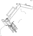
Darin zeigt: - Fig. 1
- in räumlicher Ansicht ein erstes Ausführungsbeispiel einer Radgewichtmontagevorrichtung,
- Fig. 2
- eine gegenüber der Ausführungsform gemäß
Fig. 1 veränderte Radgewichtmontagevorrichtung mit Gabelstaplerrohren, - Fig. 3
- die in
Fig. 2 dargestellte Radgewichtmontagevorrichtung beladen mit einem Radgewicht, - Fig. 4
- die in
Fig. 2 und3 räumlich dargestellte Radgewichtmontagevorrichtung in teils geschnittener Seitenansicht und mit Traktorrad, - Fig. 5
- die in
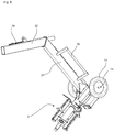
Fig. 4 dargestellte Situation in räumlicher Ansicht, - Fig. 6
- ein drittes Ausführungsbeispiel einer Radgewichtmontagevorrichtung mit Fahrwerk,
- Fig. 7
- ein viertes Ausführungsbeispiel einer Radgewichtmontagevorrichtung mit geänderten Kragarm und Radgewichtaufnahme und
- Fig. 8
- die in
Fig. 1 dargestellte Radgewichtmontagevorrichtung im Querschnitt. - In
Fig. 1 ist ein erstes Ausführungsbeispiel einer Radgewichtmontagevorrichtung in räumlicher Ansicht dargestellt. Die Radgewichtmontagevorrichtung weist einen länglichen Kragarm 1 auf, an dessen freiem Ende 11 eine Radgewichtaufnahme 2 drehbar um eine Kragarmachse 10 angeordnet ist. Die Kragarmachse 10 ist in Längserstreckung des Kragarms 1 angeordnet. - Die Radgewichtaufnahme 2 weist drei Tragkufen 21 auf, die gleichwinklig verteilt in Umfangsrichtung parallel zu der Kragarmachse 10 angeordnet sind und eine Aufnahme für einen zentralen kreisförmigen Durchgriff D des Radgewichts R bilden. Die Radgewichtaufnahme 2 weist ein Hintergreifungsmittel 22 auf, dass in hintergreifender Stellung das Radgewicht R auf der Radgewichtaufnahme 2 arretiert. Dazu ist auf der vom freien Ende 11 abwärtigen Seite der Radgewichtaufnahme 2 ein Betätigungsmittel 23 vorgesehen. Beispielsweise kann das Betätigungsmittel 23 ein Handhebel sein, der über eine Schwenkachse 24 (
Fig. 4 ) innerhalb der Tragkufe 21 das als Riegel ausgebildete Hintergreifungsmittel 22 in die rechts unten inFig. 1 dargestellte Stellung bringt und dort verriegelt. Damit die Radgewichtaufnahme 2 mit ihren Tragkufen 21 trotz geringen Spiels leicht in den Durchgriff D des Radgewichts R hineinrutschen kann, sind die Tragkufen 21 bevorzugt mit einer Auflage 25 aus einer gleitfähig ausgebildeten Kunststoffoberfläche versehen. - Um mit der Radgewichtmontagevorrichtung verschiedene Radgewichte R, insbesondere verschiedene Einbautiefen aufnehmen zu können, sind ferner an den Tragkufen 21 der Radgewichtaufnahme 2 lateral verstellbare Anschläge 26 vorgesehen. Bei richtiger Einstellung der Anschläge 26 wird das zu montierende oder abzunehmende Radgewicht R im vorderen, nahe dem freien Ende 11 des Kragarmes 1 gelegenen Ende der Radgewichtaufnahme 2 aufgenommen, um eine unmittelbare Montage innerhalb des Rades (Felge) des landwirtschaftlichen Fahrzeuges zu ermöglichen, wie in einer teils geschnittenen Darstellung in
Fig. 4 ersichtlich ist. - Um die Radgewichtmontagevorrichtung auf unterschiedliche Radgewichte R mit unterschiedlichen Innendurchmessern des Durchgriffs D verwenden zu können, sind die Tragkufen 21 austauschbar oder mittels Adapter, die auf die Tragkufen aufstülpbar sind, anpassbar ausgebildet. Somit können mit einer Radgewichtmontagevorrichtung auch Radgewichte unterschiedlicher Hersteller mit unterschiedlichen Innendurchmessern der Durchgriffsöffnung D verwendet werden. Die Anpassung mittels austauschbarer Tragkufen 21 oder zusätzlich montierbarer Adapter kann dabei sekundenschnell vorgenommen werden.
- Am Kragarm 1 ist ein Ladegeschirrbaum 3 angesetzt, der eine Hebeöse 33 nahe über dem Schwerpunkt der Radgewichtmontagevorrichtung mit aufgenommenen Radgewicht R hat. Dabei besteht der Ladegeschirrbaum 3 aus einem unteren Baum 31, der im Wesentlichen senkrecht zum Kragarm 1 ausgerichtet ist und einem oberen Baum 32. Dabei ist der obere Baum 32 in einem Winkel von 110° bis 150°, hier ca. 130° zum unteren Baum 31 über den Kragarm 1 ausgerichtet. Um eine automatische Verstellung des Schwerpunktes und somit eine im Wesentlichen horizontale Austarierung des Kragarmes 1 im unbeladenen Zustand der Radgewichtmontagevorrichtung und im beladenen Zustand erreichen zu können, ist die Hebeöse 33 am oberen Baum 32 gegen eine Federkraft verschieb- oder verschwenkbar angeschlagen. Dabei sollte die Federkraft so eingestellt sein, dass die Hebeöse 33 bei angehobener leerer Radgewichtmontagevorrichtung nicht verschwenkt und bei mit Radgewicht R beladener Radgewichtmontagevorrichtung gegen die Federkraft auf einen weiter über dem Radgewicht R orientierten Schwerpunkt verschwenkt. Dabei kann am oberen Baum 32 eine Anschlagpositionierung 34 vorgesehen sein, um verschiedene Radgewichtgrößen und -gewichte mit der Radgewichtmontagevorrichtung handhaben zu können. Je nach anzuhebendem Radgewicht R wird dann die Anschlagpositionierung 34 eingestellt. Die Federkraft wird beispielsweise von einer im oberen Baum integrierten Schraubenzugfeder oder Gasdruckfeder, ggf. auch mit Umlenkung und Übersetzung, erzeugt.
- Am unteren Baum 31 sind Handgriffe 35 zum Führen der Radgewichtmontagevorrichtung vorgesehen, insbesondere wenn diese über Hebeöse 33 an einem Kran K angehoben zu positionieren ist.
- Alternativ zur Handhabung der Radgewichtmontagevorrichtung mit einem Kran K über die Hebeöse 33 kann die gesamte Vorrichtung auch von einem Gabelstapler aufgenommen und positioniert werden. Dazu sind am Kragarm 1 Stapleraufnahmen 12 vorgesehen, durch die zwei enger eingestellte Gabeln eines Gabelstaplers einführbar sind und folglich die Vorrichtung mit Handhabung des Gabelstaplers angehoben und positioniert werden kann.
- In einer alternativen Ausführungsform gemäß
Fig. 2 sind die Stapleraufnahmen 12 mit Gabelstaplerrechteckrohren 13 versehen, um das Einführen (und Ausfädeln) der Gabelstaplergabeln zu erleichtern. Bei einer reinen Nutzung über Gabelstapler kann die Radgewichtmontagevorrichtung auch ohne Ladegeschirrbaum 3 verwendet werden. Dafür kann der Ladegeschirrbaum 3 lösbar an dem Kragarm 1 befestigt sein. Neben dem Gabelstaplerrechteckrohr 13 an der Stapleraufnahme 12 am Kragarm 1 ist das Betätigungsmittel 23 in Form des Handhebels und die verschiedene Positionierung der Riegel 22 je nach Arretierungszustand des Handhebels 23 dargestellt. Ferner ist gut erkennbar, dass die auf den Tragkufen 21 aufreitenden Anschläge 26 in drei verschiedenen Positionen eingestellt sind. Diese Positionen geben die mögliche Stärke des aufzunehmenden Radgewichts R an. Selbstverständlich werden bei Benutzung der Radgewichtmontagevorrichtung alle drei Anschläge 26 auf die gleiche Position gestellt. - In
Fig. 3 ist diese Ausführungsform der Radgewichtmontagevorrichtung räumlich mit einem angesetzten Radgewicht R dargestellt. Das Radgewicht R ist auf der Radgewichtaufnahme 2 auf den drei Tragkufen 21 bis an die Anschläge (nur sichtbar in denFiguren 2 und4 ) mit seinem Durchgriff D aufgenommen. InFig. 3 sind zwei der drei als Riegel ausgebildeten Hintergreifungsmittel 22 in die Sperrstellung verschwenkt. Das dritte Hintergreifungsmittel 22 muss noch über Betätigungshebel 23 in die Sperrstellung verschwenkt werden. Ferner ist inFig. 3 der Betätigungsraum 20, der innerhalb des Durchgriffs D des Radgewichts R freibleibt, obwohl das Radgewicht R auf der Radgewichtaufnahme 2 aufgenommen ist. Eine Montageperson kann also durch diesen Betätigungsraum 20 von außenseitig auf die Radmuttern bzw. Befestigungsmittel für das Radgewicht R zugreifen. - Ferner ist in
Fig. 3 ein Hebzeug eines Kranes K dargestellt, dass in die Hebeöse 33 am oberen Baum 32 eingreift. Im hier dargestellten angehobenen Zustand der Radgewichtmontagevorrichtung mit dem auf der Radgewichtaufnahme 2 aufgesetzten Radgewicht R ist die Hebeöse 33 gegen die Federkraft ausgeschwenkt und bis an die vorgewählte Anschlagpositionierung 34 herangeschwenkt, sodass die gesamte Radgewichtmontagevorrichtung mit Radgewicht R am Kran K so austarriert hängt, dass die Kragarmachse 10 im Wesentlichen horizontal ausgerichtet ist. Diese Situation ist auch inFig. 4 wiedergegeben. - In
Fig. 4 ist die Ausführungsform gemäßFig. 2 und3 nochmals in teils geschnittener Seitenansicht dargestellt. Neben der Radgewichtmontagevorrichtung mit Radgewicht R ist eine landwirtschaftliche Maschine L mit einem Rad, an dem das Radgewicht R angesetzt werden soll, angedeutet. - In
Fig. 4 ist im Querschnitt erkennbar, das der Betätigungsraum 20 Zugriff für einen Monteur zwischen Radgewicht R und Radgewichtaufnahme 2 erlaubt, sodass Radmuttern bzw. Befestigungsmittel für das Radgewicht R an die Felge der landwirtschaftlichen Maschine L ansetzbar sind. Die gleiche Situation ist inFig. 5 in räumlicher Ansicht dargestellt, woraus die Zuordnung der Bauteile und Lage bei Montage gut erkennbar ist. - In
Fig. 6 ist in räumlicher Ansicht eine weitere Abwandlung der Radgewichtmontagevorrichtung dargestellt, wobei die grundsätzliche Vorrichtung der Ausführung gemäßFiguren 3 und4 entspricht, wobei jedoch am Kragarm 1 ein Fahrwerk 14 mit zwei Rädern 15 vorgesehen ist, um die Radgewichtmontagevorrichtung bei Nichtgebrauch in der Werkstatt bewegen zu können, bspw. die Radgewichtmontagevorrichtung zu einem Lagerplatz oder von einem Lagerplatz zur Montagehalle zu führen. - In den
Fig. 7 und 8 ist eine Radgewichtaufnahme 2 in einer alternativen Ausgestaltung in räumlicher Ansicht (Fig. 7 ) und im Querschnitt (Fig. 8 ) entlang einer durch die Kragarmachse 10 führenden vertikalen Ebene geschnitten dargestellt. Dabei ist in dieser Ausführungsform die drehbare Lagerung der Radgewichtaufnahme 2 im Kragarm 1 aufgenommen, um einen Freiraum 27 am freien Ende der Radaufnahme 2 um die Kragarmachse 10 auszubilden. Dabei ist der Freiraum 27 so ausgestaltet, dass beispielsweise auch landwirtschaftliche Fahrzeuge mit in der Spurbreite verstellbaren Achsen mit Radgewichten versehen werden können. Bei derartigen landwirtschaftlichen Fahrzeugen stehen nämlich häufig Achsstummel im Zentrum der Radnabe vor, sodass dafür der entsprechende Freiraum 27 an der Radgewichtaufnahme 2 vorzusehen ist, damit das davon aufgenommene Radgewicht möglichst nahe an die Felge des landwirtschaftlichen Fahrzeugs zur Befestigung angelegt werden kann. Damit ist die Radgewichtaufnahme 2 mit einer in den Kragarm 1 hineinreichenden Welle 28 über dort angeordnete Wälzlager 29 drehbar um Tragarmachse 10 befestigt. - Nachfolgend wird die Montage eines Radgewichts R an einem landwirtschaftlichen Fahrzeug L mithilfe der erfindungsgemäßen Radgewichtmontagevorrichtung, insbesondere unter Bezugnahme auf
Fig. 3 bis 5 beschrieben. - Dabei wird davon ausgegangen, dass die Radgewichtmontagevorrichtung mit einem Kran K über Hebeöse 33 angehoben und gehandhabt wird. Dabei wird die Radgewichtmontagevorrichtung im nicht beladenen Zustand an dem Kran K an der Hebeöse 33 angehoben, wobei der Lagerungspunkt aufgrund der Federkraft an einer Position verbleibt, die oberhalb des Schwerpunktes der gesamten, unbeladenen Radgewichtmontagevorrichtung liegt. Entsprechend ist der Kragarm 1 beim Anheben im Wesentlichen waagerecht ausgerichtet. Nunmehr wird die Radgewichttiefe an der Radgewichtaufnahme 2 mittels der Anschläge 26 eingestellt und auch die Anschlagpositionierung 34 auf das anzuhebende Radgewicht R eingestellt.
- Dann wird mit dem Kran K die Radgewichtmontagevorrichtung zu dem zu montierenden, stehend bevorrateten Radgewicht R verbracht und die Radgewichtaufnahme 2 in die kreisrunde Durchgrifföffnung D des Radgewichts R eingeführt. Nach dem Einführen der Radgewichtaufnahme 2 in den Durchgriff D des Radgewichts R werden alle drei Handhebel 23 in die Verriegelungsposition geschwenkt, sodass die Riegel 22 das Radgewicht R hintergreifen, sodass es nicht von dem Kragarm 1 bzw. der Radgewichtaufnahme 2 abrutschen kann (
Fig. 4 ). - Nunmehr kann die Radgewichtmontagevorrichtung mit aufgenommenen Radgewicht R über den Kran K angehoben werden. Dabei verschwenkt die Hebeöse 33 gegen die Federkraft am oberen Baum 32 bis zur gewählten Anschlagspositionierung 34, sodass die Gesamtanordnung Radgewichtmontagevorrichtung mit aufgenommenem Radgewicht R austariert an der Hebeöse 33 hängt und somit der Kragarm 1 weiterhin horizontal orientiert ist. In diesem Zustand wird die Radgewichtmontagevorrichtung mit dem Kran K und unter manuellem Dirigieren an den Handgriffen 35 so an das Rad an der mit dem Radgewicht R zu versehenden Landmaschine L (
Fig. 5 ) herangeführt, dass das Radgewicht R in die Felge geführt wird. - Nunmehr wird über den frei zugänglichen Betätigungsraum 20, der sich zwischen den Tragkufen 21 der Radgewichtaufnahme 2 aufspannt, die richtige Positionierung des Radgewichts ermittelt und nötigenfalls das Radgewicht R um die Kragarmachse 10 verdreht. Da die Radgewichtaufnahme 2 über Wälzlager trotz des hohen Gewichts des Radgewichtes R leicht verdrehbar ist, können die Befestigungsbohrungen für das Radgewicht leicht ausgerichtet und mit entsprechenden Bolzen ober Radschrauben festgesetzt werden. Dabei erlaubt der freie Betätigungsraum 20 zwischen den Tragkufen 21 der Radgewichtaufnahme 2 einen ausreichend freien Zugang, sodass die Montage sachgerecht und ohne Verletzungsgefahr durchgeführt werden kann (
Fig. 4 ). - Wenn das Radgewicht ordnungsgemäß am Rad des landwirtschaftlichen Fahrzeugs L montiert ist, können dann die Handhebel 23 entriegelt und somit die hintergreifenden Riegel 22 in ihre Freistellung verschwenkt werden. Nunmehr kann unter Zuhilfenahme des Kranes K und der Handgriffe 35 die Radgewichtmontagevorrichtung mit Ihrer Radgewichtaufnahme 2 aus dem Durchgriff D des Radgewichts R herausgeführt werden. Da nunmehr das Radgewicht R nicht mehr die Radgewichtmontagevorrichtung belastet, schwenkt die Hebeöse 33 wieder federkraftbedingt in ihre ursprüngliche Stellung zurück, sodass die Radgewichtmontagevorrichtung weiterhin mit dem Kragarm 1 horizontal austariert ist. Nunmehr kann die Radgewichtmontagevorrichtung für das Montieren des Radgewichts R auf der anderen Seite der landwirtschaftlichen Maschine L verwendet werden.
- Das Abbauen von Radgewichten R erfolgt in entsprechend umgekehrter Reihenfolge, wie soeben beschrieben.
-
- 1
- Kragarm
- 10
- Kragarmachse
- 11
- freies Ende
- 12
- Gabelstapleraufnahme
- 13
- Gabelstaplerrechteckrohr
- 14
- Fahrwerk
- 15
- Rad, Rangierrad
- 2
- Radgewichtaufnahme
- 20
- Betätigungsraum
- 21
- Tragkufe
- 22
- Hintergreifungsmittel
- 23
- Betätigungsmittel
- 24
- Schwenkachse
- 25
- Auflage
- 26
- Anschlag
- 27
- Freiraum
- 28
- Welle
- 29
- Wälzlager
- 3
- Ladegeschirrbaum
- 31
- unterer Baum
- 32
- oberer Baum
- 33
- Hebeöse
- 34
- Anschlagpositionierung
- 35
- Handgriff
- D
- Durchgriff
- K
- Kran
- L
- landwirtschaftliche Maschine
- R
- Radgewicht
Claims (11)
- Radgewichtmontagevorrichtung für An- und Abbau eines Radgewichts (R) an einem Fahrzeugrad, insbesondere für landwirtschaftliche Zugmaschinen (L), wobei das Radgewicht (R) im Wesentlichen eine Kreisringscheibe mit einem zentralen Durchgriff (D) ist, dadurch gekennzeichnet, dass ein länglicher Kragarm (1) mit einem freien Ende (11) vorgesehen ist, auf dem eine um die Kragarmachse (10) des Kragarms (1) frei drehbare Radgewichtaufnahme (2) angeordnet ist, wobei die Radgewichtaufnahme (2) wenigstens drei zur Kragarmachse (10) parallel und radial so beabstandete Tragkufen (21) hat, sodass es in den zentralen Durchgriff (D) des Radgewichts (R) einschiebbar ist.
- Radgewichtmontagevorrichtung nach Anspruch 1, dadurch gekennzeichnet, dass am freien Ende (11) der Radgewichtaufnahme von einer freigegebenen in eine hintergreifende Stellung verstellbare Hintergreifungsmittel (22) vorgesehen sind, die in hintergreifender Stellung das Radgewicht (R) auf der Radgewichtaufnahme (2) arretieren.
- Radgewichtmontagevorrichtung nach Anspruch 2, dadurch gekennzeichnet, dass das Hintergreifungsmittel (22) einen um eine parallel zur Kragarmachse (10) und den Kufen (21) angeordnete Drehachse (10) verschwenkbaren Riegel hat, der über ein an der dem freien Ende (11) gegenüberliegenden Seite angeordnetes Betätigungsmittel (23) betätigbar ist.
- Radgewichtmontagevorrichtung nach Anspruch 1, 2 oder 3, dadurch gekennzeichnet, dass innerhalb des zentralen Durchgriffs (D) zwischen den Kufen (21) und dem Kragarm (1) ein frei zugänglicher Betätigungsraum (20) verbleibt, um die Befestigungsmittel für das Radgewicht (R) lösen oder ansetzen zu können.
- Radgewichtmontagevorrichtung nach Anspruch 1, 2, 3 oder 4, dadurch gekennzeichnet, dass die Tragkufen (21) mit Auflagen (25) aus einem festen und gleitfähigen Kunststoff versehen sind.
- Radgewichtmontagevorrichtung nach Anspruch 1, 2, 3, 4 oder 5, dadurch gekennzeichnet, dass der Kragarm (1) mit einem Ladegeschirrbaum (3) fest verbunden ist, der eine Hebeöse (33) nahe über dem Schwerpunkt der Radgewichtmontagevorrichtung mit dem Radgewicht (R) hat.
- Radgewichtmontagevorrichtung nach Anspruch 6, dadurch gekennzeichnet, dass der Ladegeschirrbaum (3) aus einem unteren Baum (31), der nahezu senkrecht zum Kragarm (1) ausgerichtet ist, und einem oberen Baum (32) besteht, wobei der obere Baum (32) in einem Winkel von 110° bis 150°, insbesondere 120° bis 140°, zum unteren Baum (31) über dem Kragarm (1) ausgerichtet ist.
- Radgewichtmontagevorrichtung nach Anspruch 7, dadurch gekennzeichnet, dass am oberen Baum (32) die Hebeöse (33) gegen eine Federkraft verschwenkbar oder verschiebbar ausgebildet ist.
- Radgewichtmontagevorrichtung nach Anspruch 6, 7 oder 8, dadurch gekennzeichnet, dass am Ladegeschirrbaum (3) Handgriffe (35) und/oder Rangierräder (15) vorgesehen sind.
- Radgewichtmontagevorrichtung nach Anspruch 1, 2, 3, 4 oder 5, dadurch gekennzeichnet, dass der Kragarm (1) eine Gabelstapleraufnahme (12) für eine Gabel eine Gabelstaplers aufweist.
- Verfahren für An- und Abbau eines Radgewichts (R) an einem Fahrzeugrad, insbesondere für landwirtschaftliche Zugmaschinen (L), wobei das Radgewicht (R) im Wesentlichen eine Kreisringscheibe mit einem zentralen Durchgriff (D) ist, unter Zuhilfenahme einer Radgewichtmontagevorrichtung gemäß der vorangehenden Ansprüche, dadurch gekennzeichnet, dass die frei drehbare Radgewichtaufnahme (2) mit ihren wenigstens drei zur Kragarmachse (10) parallel und radial beabstandeten Tragkufen (21) in den zentralen Durchgriff (D) des Radgewichts (R) eingeschoben und arretiert wird, die Radgewichtsmontagevorrichtung angehoben und das auf der Radgewichtsmontagevorrichtung aufgenommene Radgewicht am Fahrzeugrad der landwirtschaftlichen Zugmaschine (L) zentriert vorgehalten wird, um das Radgewicht am Fahrzeugrad befestigen zu können.
Priority Applications (1)
| Application Number | Priority Date | Filing Date | Title |
|---|---|---|---|
| PL19769373T PL3642047T3 (pl) | 2018-08-27 | 2019-08-22 | Urządzenie do montażu obciążnika koła, jak również sposób użycia tego urządzenia |
Applications Claiming Priority (2)
| Application Number | Priority Date | Filing Date | Title |
|---|---|---|---|
| DE202018104906.2U DE202018104906U1 (de) | 2018-08-27 | 2018-08-27 | Radgewichtmontagevorrichtung |
| PCT/DE2019/100759 WO2020043236A1 (de) | 2018-08-27 | 2019-08-22 | Radgewichtmontagevorrichtung sowie verfahren damit |
Publications (2)
| Publication Number | Publication Date |
|---|---|
| EP3642047A1 EP3642047A1 (de) | 2020-04-29 |
| EP3642047B1 true EP3642047B1 (de) | 2021-05-05 |
Family
ID=63588309
Family Applications (1)
| Application Number | Title | Priority Date | Filing Date |
|---|---|---|---|
| EP19769373.2A Active EP3642047B1 (de) | 2018-08-27 | 2019-08-22 | Radgewichtmontagevorrichtung sowie verfahren damit |
Country Status (5)
| Country | Link |
|---|---|
| EP (1) | EP3642047B1 (de) |
| DE (2) | DE202018104906U1 (de) |
| DK (1) | DK3642047T3 (de) |
| PL (1) | PL3642047T3 (de) |
| WO (1) | WO2020043236A1 (de) |
Families Citing this family (1)
| Publication number | Priority date | Publication date | Assignee | Title |
|---|---|---|---|---|
| FR3101574B1 (fr) * | 2019-10-03 | 2022-04-22 | Nexter Systems | Dispositif de manutention de roue et procede utilisant un tel dispositif |
Family Cites Families (6)
| Publication number | Priority date | Publication date | Assignee | Title |
|---|---|---|---|---|
| JP2959751B2 (ja) | 1995-06-14 | 1999-10-06 | 日産アルティア株式会社 | ホイールドーリー |
| DE102006014799B4 (de) | 2006-03-29 | 2009-11-19 | Gl Gmbh Metall- U. Werkstatttechnik | Radmontagelift |
| US8944521B2 (en) * | 2012-06-22 | 2015-02-03 | Deere & Company | Wheel weight assembly |
| DE102012106073A1 (de) | 2012-07-06 | 2014-01-09 | Gerhard Finkbeiner | Hebevorrichtung und Verfahren zur Montage und Demontage eines Rades mit einer solchen Hebevorrichtung |
| US9044999B2 (en) * | 2013-06-03 | 2015-06-02 | Tribine Industries, LLC | Method and apparatus for mounting and demounting large wheels |
| DE102013106240A1 (de) * | 2013-06-14 | 2014-12-18 | Dr. Ing. H.C. F. Porsche Aktiengesellschaft | Montagewagen |
-
2018
- 2018-08-27 DE DE202018104906.2U patent/DE202018104906U1/de not_active Expired - Lifetime
-
2019
- 2019-08-22 DE DE112019004262.9T patent/DE112019004262A5/de active Pending
- 2019-08-22 PL PL19769373T patent/PL3642047T3/pl unknown
- 2019-08-22 WO PCT/DE2019/100759 patent/WO2020043236A1/de not_active Ceased
- 2019-08-22 EP EP19769373.2A patent/EP3642047B1/de active Active
- 2019-08-22 DK DK19769373.2T patent/DK3642047T3/da active
Also Published As
| Publication number | Publication date |
|---|---|
| DE112019004262A5 (de) | 2021-05-27 |
| EP3642047A1 (de) | 2020-04-29 |
| PL3642047T3 (pl) | 2021-11-02 |
| DK3642047T3 (da) | 2021-07-19 |
| DE202018104906U1 (de) | 2018-09-03 |
| WO2020043236A1 (de) | 2020-03-05 |
Similar Documents
| Publication | Publication Date | Title |
|---|---|---|
| EP2870102B1 (de) | Hebevorrichtung und verfahren zur montage und demontage eines rades mit einer solchen hebevorrichtung | |
| US9623778B2 (en) | Transport system | |
| DE202010001523U1 (de) | Universeller Transportanhänger | |
| WO2020043236A1 (de) | Radgewichtmontagevorrichtung sowie verfahren damit | |
| DE102020126976A1 (de) | Aufnahmevorrichtung für ein Fräsrad einer Schlitzwandfräse und Verfahren zur Demontage eines Fräsrads | |
| DE102019126427B3 (de) | Vorrichtung zum lagegenauen Positionieren einer Transportpalette | |
| DE3827651A1 (de) | Abrutschsicherer schraubenschluessel | |
| US10398074B2 (en) | Integrated jack stand for aerator | |
| DE3924792A1 (de) | Reifenmontiergeraet | |
| DE10203017B4 (de) | Allzweck-Deckelheber für Kanal- und Schachtdeckel | |
| DE3118504C2 (de) | Transport- und Haltevorrichtung für ein Fahrzeugersatzrad | |
| EP2042411B1 (de) | Landwirtschaftliches Fahrzeug mit Ballastkörper und Betriebsverfahren dafür | |
| EP1700759B1 (de) | Sicherungseinrichtung und Sicherungsverfahren für Fahrzeuganhänger | |
| DE102017114819B4 (de) | Multifunktions-Hubeinrichtung | |
| DE2825130C3 (de) | Ersatzrad-Halterung für Lastfahrzeuge | |
| DE102021114505A1 (de) | Baumtransportvorrichtung | |
| EP4139140A2 (de) | Fahrzeuganhänger mit rangierhilfe | |
| DE69008882T2 (de) | Elektrische Antriebseinheit für Fahrzeug. | |
| DE102021117222B4 (de) | Antriebsvorrichtung zur Befestigung an einem Fahrzeugrad eines Fahrzeugs | |
| EP3708458A1 (de) | Handwagen mit einem gestell zur aufnahme eines gegenstandes, insbesondere eines abfallbehälters | |
| DE560647C (de) | Ersatzreifentraeger fuer Kraftfahrzeuge | |
| DE3930229C2 (de) | Gerät zur Reifenmontage und/oder -demontage | |
| DE4415429A1 (de) | Anbauvorrichtung für Stapler zum Handhaben insbesondere von hohlen Betonfertigteilen | |
| DE202016105063U1 (de) | Geländetransportvorrichtung für einen Rollcontainer | |
| DE10305122A1 (de) | Lithotripterfahrlafette |
Legal Events
| Date | Code | Title | Description |
|---|---|---|---|
| STAA | Information on the status of an ep patent application or granted ep patent |
Free format text: STATUS: UNKNOWN |
|
| STAA | Information on the status of an ep patent application or granted ep patent |
Free format text: STATUS: THE INTERNATIONAL PUBLICATION HAS BEEN MADE |
|
| PUAI | Public reference made under article 153(3) epc to a published international application that has entered the european phase |
Free format text: ORIGINAL CODE: 0009012 |
|
| STAA | Information on the status of an ep patent application or granted ep patent |
Free format text: STATUS: REQUEST FOR EXAMINATION WAS MADE |
|
| 17P | Request for examination filed |
Effective date: 20200122 |
|
| AK | Designated contracting states |
Kind code of ref document: A1 Designated state(s): AL AT BE BG CH CY CZ DE DK EE ES FI FR GB GR HR HU IE IS IT LI LT LU LV MC MK MT NL NO PL PT RO RS SE SI SK SM TR |
|
| AX | Request for extension of the european patent |
Extension state: BA ME |
|
| GRAP | Despatch of communication of intention to grant a patent |
Free format text: ORIGINAL CODE: EPIDOSNIGR1 |
|
| STAA | Information on the status of an ep patent application or granted ep patent |
Free format text: STATUS: GRANT OF PATENT IS INTENDED |
|
| DAV | Request for validation of the european patent (deleted) | ||
| DAX | Request for extension of the european patent (deleted) | ||
| INTG | Intention to grant announced |
Effective date: 20210115 |
|
| GRAS | Grant fee paid |
Free format text: ORIGINAL CODE: EPIDOSNIGR3 |
|
| GRAA | (expected) grant |
Free format text: ORIGINAL CODE: 0009210 |
|
| STAA | Information on the status of an ep patent application or granted ep patent |
Free format text: STATUS: THE PATENT HAS BEEN GRANTED |
|
| AK | Designated contracting states |
Kind code of ref document: B1 Designated state(s): AL AT BE BG CH CY CZ DE DK EE ES FI FR GB GR HR HU IE IS IT LI LT LU LV MC MK MT NL NO PL PT RO RS SE SI SK SM TR |
|
| REG | Reference to a national code |
Ref country code: GB Ref legal event code: FG4D Free format text: NOT ENGLISH |
|
| REG | Reference to a national code |
Ref country code: CH Ref legal event code: EP |
|
| REG | Reference to a national code |
Ref country code: AT Ref legal event code: REF Ref document number: 1389351 Country of ref document: AT Kind code of ref document: T Effective date: 20210515 |
|
| REG | Reference to a national code |
Ref country code: DE Ref legal event code: R096 Ref document number: 502019001378 Country of ref document: DE |
|
| REG | Reference to a national code |
Ref country code: IE Ref legal event code: FG4D Free format text: LANGUAGE OF EP DOCUMENT: GERMAN |
|
| REG | Reference to a national code |
Ref country code: NL Ref legal event code: FP |
|
| REG | Reference to a national code |
Ref country code: DK Ref legal event code: T3 Effective date: 20210714 |
|
| REG | Reference to a national code |
Ref country code: LT Ref legal event code: MG9D |
|
| PG25 | Lapsed in a contracting state [announced via postgrant information from national office to epo] |
Ref country code: FI Free format text: LAPSE BECAUSE OF FAILURE TO SUBMIT A TRANSLATION OF THE DESCRIPTION OR TO PAY THE FEE WITHIN THE PRESCRIBED TIME-LIMIT Effective date: 20210505 Ref country code: HR Free format text: LAPSE BECAUSE OF FAILURE TO SUBMIT A TRANSLATION OF THE DESCRIPTION OR TO PAY THE FEE WITHIN THE PRESCRIBED TIME-LIMIT Effective date: 20210505 Ref country code: LT Free format text: LAPSE BECAUSE OF FAILURE TO SUBMIT A TRANSLATION OF THE DESCRIPTION OR TO PAY THE FEE WITHIN THE PRESCRIBED TIME-LIMIT Effective date: 20210505 Ref country code: BG Free format text: LAPSE BECAUSE OF FAILURE TO SUBMIT A TRANSLATION OF THE DESCRIPTION OR TO PAY THE FEE WITHIN THE PRESCRIBED TIME-LIMIT Effective date: 20210805 |
|
| PG25 | Lapsed in a contracting state [announced via postgrant information from national office to epo] |
Ref country code: NO Free format text: LAPSE BECAUSE OF FAILURE TO SUBMIT A TRANSLATION OF THE DESCRIPTION OR TO PAY THE FEE WITHIN THE PRESCRIBED TIME-LIMIT Effective date: 20210805 Ref country code: LV Free format text: LAPSE BECAUSE OF FAILURE TO SUBMIT A TRANSLATION OF THE DESCRIPTION OR TO PAY THE FEE WITHIN THE PRESCRIBED TIME-LIMIT Effective date: 20210505 Ref country code: SE Free format text: LAPSE BECAUSE OF FAILURE TO SUBMIT A TRANSLATION OF THE DESCRIPTION OR TO PAY THE FEE WITHIN THE PRESCRIBED TIME-LIMIT Effective date: 20210505 Ref country code: PT Free format text: LAPSE BECAUSE OF FAILURE TO SUBMIT A TRANSLATION OF THE DESCRIPTION OR TO PAY THE FEE WITHIN THE PRESCRIBED TIME-LIMIT Effective date: 20210906 Ref country code: RS Free format text: LAPSE BECAUSE OF FAILURE TO SUBMIT A TRANSLATION OF THE DESCRIPTION OR TO PAY THE FEE WITHIN THE PRESCRIBED TIME-LIMIT Effective date: 20210505 Ref country code: GR Free format text: LAPSE BECAUSE OF FAILURE TO SUBMIT A TRANSLATION OF THE DESCRIPTION OR TO PAY THE FEE WITHIN THE PRESCRIBED TIME-LIMIT Effective date: 20210806 Ref country code: IS Free format text: LAPSE BECAUSE OF FAILURE TO SUBMIT A TRANSLATION OF THE DESCRIPTION OR TO PAY THE FEE WITHIN THE PRESCRIBED TIME-LIMIT Effective date: 20210905 |
|
| PG25 | Lapsed in a contracting state [announced via postgrant information from national office to epo] |
Ref country code: RO Free format text: LAPSE BECAUSE OF FAILURE TO SUBMIT A TRANSLATION OF THE DESCRIPTION OR TO PAY THE FEE WITHIN THE PRESCRIBED TIME-LIMIT Effective date: 20210505 Ref country code: SM Free format text: LAPSE BECAUSE OF FAILURE TO SUBMIT A TRANSLATION OF THE DESCRIPTION OR TO PAY THE FEE WITHIN THE PRESCRIBED TIME-LIMIT Effective date: 20210505 Ref country code: CZ Free format text: LAPSE BECAUSE OF FAILURE TO SUBMIT A TRANSLATION OF THE DESCRIPTION OR TO PAY THE FEE WITHIN THE PRESCRIBED TIME-LIMIT Effective date: 20210505 Ref country code: SK Free format text: LAPSE BECAUSE OF FAILURE TO SUBMIT A TRANSLATION OF THE DESCRIPTION OR TO PAY THE FEE WITHIN THE PRESCRIBED TIME-LIMIT Effective date: 20210505 Ref country code: ES Free format text: LAPSE BECAUSE OF FAILURE TO SUBMIT A TRANSLATION OF THE DESCRIPTION OR TO PAY THE FEE WITHIN THE PRESCRIBED TIME-LIMIT Effective date: 20210505 Ref country code: EE Free format text: LAPSE BECAUSE OF FAILURE TO SUBMIT A TRANSLATION OF THE DESCRIPTION OR TO PAY THE FEE WITHIN THE PRESCRIBED TIME-LIMIT Effective date: 20210505 |
|
| REG | Reference to a national code |
Ref country code: DE Ref legal event code: R097 Ref document number: 502019001378 Country of ref document: DE |
|
| PLBE | No opposition filed within time limit |
Free format text: ORIGINAL CODE: 0009261 |
|
| STAA | Information on the status of an ep patent application or granted ep patent |
Free format text: STATUS: NO OPPOSITION FILED WITHIN TIME LIMIT |
|
| PG25 | Lapsed in a contracting state [announced via postgrant information from national office to epo] |
Ref country code: MC Free format text: LAPSE BECAUSE OF FAILURE TO SUBMIT A TRANSLATION OF THE DESCRIPTION OR TO PAY THE FEE WITHIN THE PRESCRIBED TIME-LIMIT Effective date: 20210505 |
|
| 26N | No opposition filed |
Effective date: 20220208 |
|
| REG | Reference to a national code |
Ref country code: BE Ref legal event code: MM Effective date: 20210831 |
|
| PG25 | Lapsed in a contracting state [announced via postgrant information from national office to epo] |
Ref country code: IS Free format text: LAPSE BECAUSE OF FAILURE TO SUBMIT A TRANSLATION OF THE DESCRIPTION OR TO PAY THE FEE WITHIN THE PRESCRIBED TIME-LIMIT Effective date: 20210905 Ref country code: LU Free format text: LAPSE BECAUSE OF NON-PAYMENT OF DUE FEES Effective date: 20210822 Ref country code: AL Free format text: LAPSE BECAUSE OF FAILURE TO SUBMIT A TRANSLATION OF THE DESCRIPTION OR TO PAY THE FEE WITHIN THE PRESCRIBED TIME-LIMIT Effective date: 20210505 |
|
| PG25 | Lapsed in a contracting state [announced via postgrant information from national office to epo] |
Ref country code: BE Free format text: LAPSE BECAUSE OF NON-PAYMENT OF DUE FEES Effective date: 20210831 |
|
| REG | Reference to a national code |
Ref country code: CH Ref legal event code: PL |
|
| PG25 | Lapsed in a contracting state [announced via postgrant information from national office to epo] |
Ref country code: LI Free format text: LAPSE BECAUSE OF NON-PAYMENT OF DUE FEES Effective date: 20220831 Ref country code: CH Free format text: LAPSE BECAUSE OF NON-PAYMENT OF DUE FEES Effective date: 20220831 |
|
| PG25 | Lapsed in a contracting state [announced via postgrant information from national office to epo] |
Ref country code: CY Free format text: LAPSE BECAUSE OF FAILURE TO SUBMIT A TRANSLATION OF THE DESCRIPTION OR TO PAY THE FEE WITHIN THE PRESCRIBED TIME-LIMIT Effective date: 20210505 |
|
| PG25 | Lapsed in a contracting state [announced via postgrant information from national office to epo] |
Ref country code: LI Free format text: LAPSE BECAUSE OF NON-PAYMENT OF DUE FEES Effective date: 20220831 Ref country code: HU Free format text: LAPSE BECAUSE OF FAILURE TO SUBMIT A TRANSLATION OF THE DESCRIPTION OR TO PAY THE FEE WITHIN THE PRESCRIBED TIME-LIMIT; INVALID AB INITIO Effective date: 20190822 Ref country code: CH Free format text: LAPSE BECAUSE OF NON-PAYMENT OF DUE FEES Effective date: 20220831 |
|
| PGRI | Patent reinstated in contracting state [announced from national office to epo] |
Ref country code: LI Effective date: 20230524 Ref country code: CH Effective date: 20230524 |
|
| REG | Reference to a national code |
Ref country code: CH Ref legal event code: PL |
|
| PG25 | Lapsed in a contracting state [announced via postgrant information from national office to epo] |
Ref country code: MK Free format text: LAPSE BECAUSE OF FAILURE TO SUBMIT A TRANSLATION OF THE DESCRIPTION OR TO PAY THE FEE WITHIN THE PRESCRIBED TIME-LIMIT Effective date: 20210505 Ref country code: CH Free format text: LAPSE BECAUSE OF NON-PAYMENT OF DUE FEES Effective date: 20230831 |
|
| PG25 | Lapsed in a contracting state [announced via postgrant information from national office to epo] |
Ref country code: TR Free format text: LAPSE BECAUSE OF FAILURE TO SUBMIT A TRANSLATION OF THE DESCRIPTION OR TO PAY THE FEE WITHIN THE PRESCRIBED TIME-LIMIT Effective date: 20210505 |
|
| PG25 | Lapsed in a contracting state [announced via postgrant information from national office to epo] |
Ref country code: CH Free format text: LAPSE BECAUSE OF NON-PAYMENT OF DUE FEES Effective date: 20230831 |
|
| PGFP | Annual fee paid to national office [announced via postgrant information from national office to epo] |
Ref country code: CH Payment date: 20240607 Year of fee payment: 5 |
|
| PGRI | Patent reinstated in contracting state [announced from national office to epo] |
Ref country code: CH Effective date: 20240607 |
|
| PG25 | Lapsed in a contracting state [announced via postgrant information from national office to epo] |
Ref country code: CH Free format text: LAPSE BECAUSE OF NON-PAYMENT OF DUE FEES Effective date: 20230831 |
|
| PGRI | Patent reinstated in contracting state [announced from national office to epo] |
Ref country code: CH Effective date: 20240607 |
|
| PG25 | Lapsed in a contracting state [announced via postgrant information from national office to epo] |
Ref country code: MT Free format text: LAPSE BECAUSE OF FAILURE TO SUBMIT A TRANSLATION OF THE DESCRIPTION OR TO PAY THE FEE WITHIN THE PRESCRIBED TIME-LIMIT Effective date: 20210505 |
|
| REG | Reference to a national code |
Ref country code: CH Ref legal event code: PL |
|
| PG25 | Lapsed in a contracting state [announced via postgrant information from national office to epo] |
Ref country code: CH Free format text: LAPSE BECAUSE OF NON-PAYMENT OF DUE FEES Effective date: 20240831 |
|
| PGFP | Annual fee paid to national office [announced via postgrant information from national office to epo] |
Ref country code: NL Payment date: 20250821 Year of fee payment: 7 |
|
| PGFP | Annual fee paid to national office [announced via postgrant information from national office to epo] |
Ref country code: DE Payment date: 20250819 Year of fee payment: 7 Ref country code: DK Payment date: 20250821 Year of fee payment: 7 |
|
| PGFP | Annual fee paid to national office [announced via postgrant information from national office to epo] |
Ref country code: PL Payment date: 20250808 Year of fee payment: 7 Ref country code: IT Payment date: 20250829 Year of fee payment: 7 |
|
| PGFP | Annual fee paid to national office [announced via postgrant information from national office to epo] |
Ref country code: GB Payment date: 20250822 Year of fee payment: 7 |
|
| PGFP | Annual fee paid to national office [announced via postgrant information from national office to epo] |
Ref country code: FR Payment date: 20250821 Year of fee payment: 7 Ref country code: AT Payment date: 20250819 Year of fee payment: 7 |
|
| PGFP | Annual fee paid to national office [announced via postgrant information from national office to epo] |
Ref country code: IE Payment date: 20250821 Year of fee payment: 7 |