EP3642004B1 - Anlage, unterbaugruppe und verfahren zur koextrusion - Google Patents
Anlage, unterbaugruppe und verfahren zur koextrusion Download PDFInfo
- Publication number
- EP3642004B1 EP3642004B1 EP18749441.4A EP18749441A EP3642004B1 EP 3642004 B1 EP3642004 B1 EP 3642004B1 EP 18749441 A EP18749441 A EP 18749441A EP 3642004 B1 EP3642004 B1 EP 3642004B1
- Authority
- EP
- European Patent Office
- Prior art keywords
- extruder
- screw
- rubber compound
- outlet
- piston pump
- Prior art date
- Legal status (The legal status is an assumption and is not a legal conclusion. Google has not performed a legal analysis and makes no representation as to the accuracy of the status listed.)
- Active
Links
Images

Classifications
-
- F—MECHANICAL ENGINEERING; LIGHTING; HEATING; WEAPONS; BLASTING
- F04—POSITIVE - DISPLACEMENT MACHINES FOR LIQUIDS; PUMPS FOR LIQUIDS OR ELASTIC FLUIDS
- F04B—POSITIVE-DISPLACEMENT MACHINES FOR LIQUIDS; PUMPS
- F04B7/00—Piston machines or pumps characterised by having positively-driven valving
- F04B7/0019—Piston machines or pumps characterised by having positively-driven valving a common distribution member forming a single discharge distributor for a plurality of pumping chambers
- F04B7/0023—Piston machines or pumps characterised by having positively-driven valving a common distribution member forming a single discharge distributor for a plurality of pumping chambers and having a rotating movement
-
- B—PERFORMING OPERATIONS; TRANSPORTING
- B29—WORKING OF PLASTICS; WORKING OF SUBSTANCES IN A PLASTIC STATE IN GENERAL
- B29C—SHAPING OR JOINING OF PLASTICS; SHAPING OF MATERIAL IN A PLASTIC STATE, NOT OTHERWISE PROVIDED FOR; AFTER-TREATMENT OF THE SHAPED PRODUCTS, e.g. REPAIRING
- B29C48/00—Extrusion moulding, i.e. expressing the moulding material through a die or nozzle which imparts the desired form; Apparatus therefor
- B29C48/16—Articles comprising two or more components, e.g. co-extruded layers
-
- B—PERFORMING OPERATIONS; TRANSPORTING
- B29—WORKING OF PLASTICS; WORKING OF SUBSTANCES IN A PLASTIC STATE IN GENERAL
- B29C—SHAPING OR JOINING OF PLASTICS; SHAPING OF MATERIAL IN A PLASTIC STATE, NOT OTHERWISE PROVIDED FOR; AFTER-TREATMENT OF THE SHAPED PRODUCTS, e.g. REPAIRING
- B29C48/00—Extrusion moulding, i.e. expressing the moulding material through a die or nozzle which imparts the desired form; Apparatus therefor
- B29C48/25—Component parts, details or accessories; Auxiliary operations
- B29C48/36—Means for plasticising or homogenising the moulding material or forcing it through the nozzle or die
- B29C48/375—Plasticisers, homogenisers or feeders comprising two or more stages
- B29C48/388—Plasticisers, homogenisers or feeders comprising two or more stages using a screw extruder and a ram or piston
-
- B—PERFORMING OPERATIONS; TRANSPORTING
- B29—WORKING OF PLASTICS; WORKING OF SUBSTANCES IN A PLASTIC STATE IN GENERAL
- B29C—SHAPING OR JOINING OF PLASTICS; SHAPING OF MATERIAL IN A PLASTIC STATE, NOT OTHERWISE PROVIDED FOR; AFTER-TREATMENT OF THE SHAPED PRODUCTS, e.g. REPAIRING
- B29C48/00—Extrusion moulding, i.e. expressing the moulding material through a die or nozzle which imparts the desired form; Apparatus therefor
- B29C48/25—Component parts, details or accessories; Auxiliary operations
- B29C48/36—Means for plasticising or homogenising the moulding material or forcing it through the nozzle or die
- B29C48/475—Means for plasticising or homogenising the moulding material or forcing it through the nozzle or die using pistons, accumulators or press rams
-
- B—PERFORMING OPERATIONS; TRANSPORTING
- B29—WORKING OF PLASTICS; WORKING OF SUBSTANCES IN A PLASTIC STATE IN GENERAL
- B29C—SHAPING OR JOINING OF PLASTICS; SHAPING OF MATERIAL IN A PLASTIC STATE, NOT OTHERWISE PROVIDED FOR; AFTER-TREATMENT OF THE SHAPED PRODUCTS, e.g. REPAIRING
- B29C48/00—Extrusion moulding, i.e. expressing the moulding material through a die or nozzle which imparts the desired form; Apparatus therefor
- B29C48/25—Component parts, details or accessories; Auxiliary operations
- B29C48/36—Means for plasticising or homogenising the moulding material or forcing it through the nozzle or die
- B29C48/475—Means for plasticising or homogenising the moulding material or forcing it through the nozzle or die using pistons, accumulators or press rams
- B29C48/485—Hydrostatic extrusion
-
- B—PERFORMING OPERATIONS; TRANSPORTING
- B29—WORKING OF PLASTICS; WORKING OF SUBSTANCES IN A PLASTIC STATE IN GENERAL
- B29C—SHAPING OR JOINING OF PLASTICS; SHAPING OF MATERIAL IN A PLASTIC STATE, NOT OTHERWISE PROVIDED FOR; AFTER-TREATMENT OF THE SHAPED PRODUCTS, e.g. REPAIRING
- B29C48/00—Extrusion moulding, i.e. expressing the moulding material through a die or nozzle which imparts the desired form; Apparatus therefor
- B29C48/25—Component parts, details or accessories; Auxiliary operations
- B29C48/36—Means for plasticising or homogenising the moulding material or forcing it through the nozzle or die
- B29C48/49—Means for plasticising or homogenising the moulding material or forcing it through the nozzle or die using two or more extruders to feed one die or nozzle
-
- F—MECHANICAL ENGINEERING; LIGHTING; HEATING; WEAPONS; BLASTING
- F04—POSITIVE - DISPLACEMENT MACHINES FOR LIQUIDS; PUMPS FOR LIQUIDS OR ELASTIC FLUIDS
- F04B—POSITIVE-DISPLACEMENT MACHINES FOR LIQUIDS; PUMPS
- F04B1/00—Multi-cylinder machines or pumps characterised by number or arrangement of cylinders
- F04B1/12—Multi-cylinder machines or pumps characterised by number or arrangement of cylinders having cylinder axes coaxial with, or parallel or inclined to, main shaft axis
- F04B1/14—Multi-cylinder machines or pumps characterised by number or arrangement of cylinders having cylinder axes coaxial with, or parallel or inclined to, main shaft axis having stationary cylinders
- F04B1/141—Details or component parts
-
- F—MECHANICAL ENGINEERING; LIGHTING; HEATING; WEAPONS; BLASTING
- F04—POSITIVE - DISPLACEMENT MACHINES FOR LIQUIDS; PUMPS FOR LIQUIDS OR ELASTIC FLUIDS
- F04B—POSITIVE-DISPLACEMENT MACHINES FOR LIQUIDS; PUMPS
- F04B1/00—Multi-cylinder machines or pumps characterised by number or arrangement of cylinders
- F04B1/12—Multi-cylinder machines or pumps characterised by number or arrangement of cylinders having cylinder axes coaxial with, or parallel or inclined to, main shaft axis
- F04B1/14—Multi-cylinder machines or pumps characterised by number or arrangement of cylinders having cylinder axes coaxial with, or parallel or inclined to, main shaft axis having stationary cylinders
- F04B1/18—Multi-cylinder machines or pumps characterised by number or arrangement of cylinders having cylinder axes coaxial with, or parallel or inclined to, main shaft axis having stationary cylinders having self-acting distribution members, i.e. actuated by working fluid
- F04B1/184—Cylindrical distribution members
-
- F—MECHANICAL ENGINEERING; LIGHTING; HEATING; WEAPONS; BLASTING
- F04—POSITIVE - DISPLACEMENT MACHINES FOR LIQUIDS; PUMPS FOR LIQUIDS OR ELASTIC FLUIDS
- F04B—POSITIVE-DISPLACEMENT MACHINES FOR LIQUIDS; PUMPS
- F04B1/00—Multi-cylinder machines or pumps characterised by number or arrangement of cylinders
- F04B1/12—Multi-cylinder machines or pumps characterised by number or arrangement of cylinders having cylinder axes coaxial with, or parallel or inclined to, main shaft axis
- F04B1/20—Multi-cylinder machines or pumps characterised by number or arrangement of cylinders having cylinder axes coaxial with, or parallel or inclined to, main shaft axis having rotary cylinder block
- F04B1/22—Multi-cylinder machines or pumps characterised by number or arrangement of cylinders having cylinder axes coaxial with, or parallel or inclined to, main shaft axis having rotary cylinder block having two or more sets of cylinders or pistons
-
- F—MECHANICAL ENGINEERING; LIGHTING; HEATING; WEAPONS; BLASTING
- F04—POSITIVE - DISPLACEMENT MACHINES FOR LIQUIDS; PUMPS FOR LIQUIDS OR ELASTIC FLUIDS
- F04B—POSITIVE-DISPLACEMENT MACHINES FOR LIQUIDS; PUMPS
- F04B15/00—Pumps adapted to handle specific fluids, e.g. by selection of specific materials for pumps or pump parts
- F04B15/02—Pumps adapted to handle specific fluids, e.g. by selection of specific materials for pumps or pump parts the fluids being viscous or non-homogeneous
-
- F—MECHANICAL ENGINEERING; LIGHTING; HEATING; WEAPONS; BLASTING
- F04—POSITIVE - DISPLACEMENT MACHINES FOR LIQUIDS; PUMPS FOR LIQUIDS OR ELASTIC FLUIDS
- F04B—POSITIVE-DISPLACEMENT MACHINES FOR LIQUIDS; PUMPS
- F04B23/00—Pumping installations or systems
- F04B23/04—Combinations of two or more pumps
- F04B23/06—Combinations of two or more pumps the pumps being all of reciprocating positive-displacement type
-
- F—MECHANICAL ENGINEERING; LIGHTING; HEATING; WEAPONS; BLASTING
- F04—POSITIVE - DISPLACEMENT MACHINES FOR LIQUIDS; PUMPS FOR LIQUIDS OR ELASTIC FLUIDS
- F04B—POSITIVE-DISPLACEMENT MACHINES FOR LIQUIDS; PUMPS
- F04B53/00—Component parts, details or accessories not provided for in, or of interest apart from, groups F04B1/00 - F04B23/00 or F04B39/00 - F04B47/00
- F04B53/10—Valves; Arrangement of valves
-
- B—PERFORMING OPERATIONS; TRANSPORTING
- B29—WORKING OF PLASTICS; WORKING OF SUBSTANCES IN A PLASTIC STATE IN GENERAL
- B29B—PREPARATION OR PRETREATMENT OF THE MATERIAL TO BE SHAPED; MAKING GRANULES OR PREFORMS; RECOVERY OF PLASTICS OR OTHER CONSTITUENTS OF WASTE MATERIAL CONTAINING PLASTICS
- B29B7/00—Mixing; Kneading
- B29B7/74—Mixing; Kneading using other mixers or combinations of mixers, e.g. of dissimilar mixers ; Plant
- B29B7/7476—Systems, i.e. flow charts or diagrams; Plants
- B29B7/7495—Systems, i.e. flow charts or diagrams; Plants for mixing rubber
-
- B—PERFORMING OPERATIONS; TRANSPORTING
- B29—WORKING OF PLASTICS; WORKING OF SUBSTANCES IN A PLASTIC STATE IN GENERAL
- B29C—SHAPING OR JOINING OF PLASTICS; SHAPING OF MATERIAL IN A PLASTIC STATE, NOT OTHERWISE PROVIDED FOR; AFTER-TREATMENT OF THE SHAPED PRODUCTS, e.g. REPAIRING
- B29C48/00—Extrusion moulding, i.e. expressing the moulding material through a die or nozzle which imparts the desired form; Apparatus therefor
- B29C48/25—Component parts, details or accessories; Auxiliary operations
- B29C48/285—Feeding the extrusion material to the extruder
- B29C48/286—Raw material dosing
-
- B—PERFORMING OPERATIONS; TRANSPORTING
- B29—WORKING OF PLASTICS; WORKING OF SUBSTANCES IN A PLASTIC STATE IN GENERAL
- B29C—SHAPING OR JOINING OF PLASTICS; SHAPING OF MATERIAL IN A PLASTIC STATE, NOT OTHERWISE PROVIDED FOR; AFTER-TREATMENT OF THE SHAPED PRODUCTS, e.g. REPAIRING
- B29C48/00—Extrusion moulding, i.e. expressing the moulding material through a die or nozzle which imparts the desired form; Apparatus therefor
- B29C48/25—Component parts, details or accessories; Auxiliary operations
- B29C48/36—Means for plasticising or homogenising the moulding material or forcing it through the nozzle or die
- B29C48/365—Means for plasticising or homogenising the moulding material or forcing it through the nozzle or die using pumps, e.g. piston pumps
-
- B—PERFORMING OPERATIONS; TRANSPORTING
- B29—WORKING OF PLASTICS; WORKING OF SUBSTANCES IN A PLASTIC STATE IN GENERAL
- B29C—SHAPING OR JOINING OF PLASTICS; SHAPING OF MATERIAL IN A PLASTIC STATE, NOT OTHERWISE PROVIDED FOR; AFTER-TREATMENT OF THE SHAPED PRODUCTS, e.g. REPAIRING
- B29C48/00—Extrusion moulding, i.e. expressing the moulding material through a die or nozzle which imparts the desired form; Apparatus therefor
- B29C48/25—Component parts, details or accessories; Auxiliary operations
- B29C48/36—Means for plasticising or homogenising the moulding material or forcing it through the nozzle or die
- B29C48/395—Means for plasticising or homogenising the moulding material or forcing it through the nozzle or die using screws surrounded by a cooperating barrel, e.g. single screw extruders
- B29C48/45—Axially movable screws
-
- B—PERFORMING OPERATIONS; TRANSPORTING
- B29—WORKING OF PLASTICS; WORKING OF SUBSTANCES IN A PLASTIC STATE IN GENERAL
- B29K—INDEXING SCHEME ASSOCIATED WITH SUBCLASSES B29B, B29C OR B29D, RELATING TO MOULDING MATERIALS OR TO MATERIALS FOR MOULDS, REINFORCEMENTS, FILLERS OR PREFORMED PARTS, e.g. INSERTS
- B29K2007/00—Use of natural rubber as moulding material
Definitions
- the invention relates to the field of extrusion of rubber mixtures, more particularly intended for the manufacture of tires. More particularly, it relates to the manufacture of coextruded profiles based on rubber mixtures of different compositions used in particular for manufacturing a tread or a tire sidewall.
- an installation for manufacturing complex profiles by extruding at least two rubber compounds of different compositions, or coextrusion comprises at least two extruders connected to an extrusion head.
- Each extruder is formed of a cylindrical body or barrel which is fixed inside which is a screw coaxial with the longitudinal axis of the barrel and driven in rotation around it. Its function is to homogenize and push a rubber mixture towards an orifice or outlet after having received it in the form of a strip of mixture at a feed orifice.
- the outlet orifice of each extruder opens into a common extrusion head which thus receives rubber compounds of different compositions and comprises at the outlet an extrusion die which defines the profile of the rubber strip.
- This profile is defined by a fixed profiled blade or a fixed profiled wall cooperating with a rotating roller.
- Tire manufacturing increasingly uses complex products obtained in the form of complex semi-finished products in order to reduce the number of successive product installations in assembly and thus reduce costs and increase precision.
- a profiling device or output die into which the different mixtures from different extruders arrive, in the form of extrudates that do not mix, in order to form the complex coextruded profile at the output.
- the geometric shape and dimensions of the profiling device are determined by several successive iteration loops. Once the device has been developed, it only gives the expected results when the extruders operate in continuous mode and at a well-defined speed.
- the non-compliant coextruded profile currently represents a significant part of the machine's production.
- the so-called mixed (or multi-compound) waste must be stored, rehomogenized and reintroduced in a controlled manner, precisely dosed, in the following productions.
- the additional manufacturing cost that this generates is also accompanied by a drop in the performance of the product finally obtained which is partly polluted by the other mixtures.
- the coextruded product must be continuously controlled, by measuring the linear weight of the outgoing product and comparing it to a pre-established weight.
- the shape and dimensions of the complex product (width, thickness) using different sensors.
- An objective of the invention is to remedy the drawbacks of the aforementioned documents and to propose a coextrusion installation for elastomer mixtures whose flow rate can be adjusted very precisely.
- each extruder in a coextrusion plant is connected to a volumetric piston pump (comprising one or more pistons) which precisely doses the quantity of elastomer mixture sent into each channel connecting it to the extrusion head.
- a volumetric piston pump comprising one or more pistons which precisely doses the quantity of elastomer mixture sent into each channel connecting it to the extrusion head.
- said pump is a pump comprising two axial pistons with axes parallel to the longitudinal axis of the extruder.
- Such an axial piston volumetric pump is a pump comprising a chamber for pressurizing the elastomer mixture (or rubber) as well as two rubber metering chambers cooperating with the pressurizing chamber. Each metering chamber opens into a rubber circulation channel which, in turn, opens into an intake chamber of a rubber (or elastomer mixture) distribution member.
- the pump also comprises two pistons with axes parallel to the longitudinal axis of the extruder, the pistons being movable in the metering chambers between a top dead center TDC and a bottom dead center PMB in an alternating translational movement.
- the pump is a positive displacement pump adapted to operation with a rubber mixture. Such a pump is better described in the documents EP0400496 And EP0690229 .
- the axial piston pump is arranged at the outlet of the extruder. This makes it possible to obtain extremely precise dosage of the rubber, while allowing the mixture to exit radially by the shortest path and thus limit the rise in its temperature.
- the axes of the extruders are parallel to each other, for a more compact installation and easier flow of the mixtures towards the extrusion head.
- the axial piston pump is arranged upstream of the extruder outlet. This makes it possible to use the downstream part of the extruder screw to completely empty the outlet channel.
- the extruder axes are at an acute angle to each other.
- the longitudinal axes of the extrusion screws of the extruders are arranged so as to converge the mixtures they transport towards the extrusion head of the coextruded profile.
- the longitudinal axis of an extruder makes an acute angle (less than 90°) with the axis of the adjacent extruder.
- the coextruded profile is thus obtained by coextrusion of the two separate mixture flows, via flow channels which connect the outlet of the extruders to the extrusion head.
- the extrusion head is of the flat nose type or it has a profiled fixed blade which cooperates with a rotating roller on which the coextruded product is placed.
- the axes of the extruders are each arranged in a vertical plane or inclined relative to a vertical plane.
- the installation comprises a control unit which synchronizes the rotation speed of the screw with the frequency of the reciprocating movement of the pistons of the axial piston pump.
- the speed of the extruder screw is chosen proportionally to the frequency of the reciprocating movement of the pistons and therefore to the filling of the metering chambers of the pump and also according to the amount of shear that is to be applied to the mixture. For example, a reduced screw speed provides more shear and heating to the mixture, while a screw speed close to that of the gears ensures a faster transfer of the mixture to the extruder outlet.
- the objective of the invention is also achieved with a coextrusion process for producing a complex profile for tires made from rubber mixtures of different compositions comprising at least a first extruder comprising a screw having a longitudinal axis and at least a second extruder comprising a screw having a longitudinal axis and an extrusion head connected to each of said extruders by suitable channels, characterized in that the screw of each extruder is the elastomer mixture feeding element of a piston pump.
- the rotation speed of the screw is synchronized with the frequency of the reciprocating movement of the pistons of the piston pump.
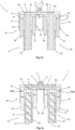
- FIGS. 1a and 1b illustrate a coextrusion installation 1 according to a first embodiment of the invention.
- the sectional view is produced with a plane which is parallel to the plane of symmetry of an extrusion head 2 (configuration better visible at fig. 3c ).
- the installation comprises two extruders 10 and 20 which each deliver an elastomer mixture of different composition which arrives in the extrusion head 2 via a channel 11, respectively 21.
- rubber or elastomer we preferably mean any type of elastomer, diene or non-diene for example thermoplastic, or a mixture of elastomers: natural rubber and synthetic rubber, reinforcing fillers: carbon black and silica, plasticizers: oils, resins, and other chemical elements such as sulfur for example.
- the extrusion installation of the invention aims to produce a coextruded profile based on different mixtures.
- Such mixtures of different elastomers are, for example, the elastomer or gum mixtures used to create a tread assembly such as: a first material made of 100% natural rubber to produce an underlayer with one, then a second material to produce the tread 100% synthetic rubber bearing.
- a third or even a fourth material can be added to make the sidewalls composed of a mixture of natural rubber/synthetic rubber (20% to 80% natural rubber).
- the extruder 10 comprises an extrusion screw 12 or Archimedes screw and a sleeve 14 for receiving the screw which is driven in rotation, about its longitudinal axis 13, at its upstream end, by a geared motor of known type (not illustrated in the drawings).
- the sleeve 14 comprises a feed inlet 16 for elastomer mixture and an outlet 17 which opens into a transfer channel 6 for the mixture in the channel 11.
- the extruder 20 comprises an extrusion screw 22 or Archimedes screw and a sleeve 24 for receiving the screw which is rotated, about its longitudinal axis 23, at its upstream end, by a geared motor of known type (not shown in the drawings).
- the sleeve 24 comprises a feed inlet 26 for elastomer mixture and an outlet 27 which opens into a transfer channel 7 for the mixture in the channel 21.
- the longitudinal axes 13 and 23 of the extrusion screws are parallel to each other and are perpendicular to the transfer channels 6, 7 which each connect the outlet of an extruder to the extrusion head 2 and are located in the axis of symmetry of the latter.
- the screw 13, 23 of each extruder 10, 20 constitutes the feeding element of a piston pump 30, 40, in particular a volumetric pump with axial pistons.
- a volumetric pump with axial pistons used with a coextrusion installation makes it possible to dose the mixture of elastomers used to manufacture a complex product by coextrusion.
- the axial piston volumetric pump 30 comprises a pump body 31 delimiting a chamber 32 for pressurizing the elastomer mixture (or rubber). It also comprises a first 33 and a second 34 rubber metering chamber cooperating with the pressurizing chamber 32 by means of communication orifices 35. Each metering chamber opens into a channel 51, 52 for circulating the rubber which, in turn, opens into an intake chamber 53 of a distribution member 55 for the rubber (or rubber mixture).
- the pump comprises also two pistons 36, 37 with axes parallel to the longitudinal axis of the extruder, the pistons being movable in sliding in the dosing chambers 33, 34 between a top dead center TDC and a bottom dead center PMB according to an alternating translational movement.
- the axial piston volumetric pump 40 comprises a pump body 41 delimiting a chamber 42 for pressurizing the elastomer mixture (or rubber). It also comprises a first 43 and a second 44 rubber metering chamber cooperating with the pressurizing chamber 42 by means of communication orifices 45. Each metering chamber opens into a channel 61, 62 for circulating the rubber which, in turn, opens into an intake chamber 63 of a rubber (or rubber mixture) distribution member.
- the pump also comprises two pistons 46, 47 with axes parallel to the longitudinal axis of the extruder, the pistons being movable in sliding in the metering chambers 43, 44 between a top dead center TDC and a bottom dead center PMB according to an alternating translational movement.
- the intake chamber 53, 63 of each pump opens into a discharge channel 6, respectively 7 of the rubber which communicate directly with the flow channels 11, 21 of the extrusion head 2.
- the screw 12, respectively 22 of the extruder 10, respectively 20 comprises a threaded axial part for shearing the elastomer mixture when it is rotated about its main or longitudinal axis inside the barrel of the extruder. This makes it possible to mix, homogenize and heat the mixture.
- the upper axial end (mixture outlet side) of each screw 12, respectively 22 forms the distribution member 55, 65 of the pump 30, respectively 40.
- the screw 12, respectively 22 of each extruder 10, 20 is rotated and the pistons 36, 37, respectively 46, 47 are moved in the metering chambers 33, 34, respectively 43, 44 of the pump 30, respectively 40.
- the pistons are movable in the metering chambers between a top dead center TDC, which corresponds to a phase of delivery of the rubber from the metering chamber to the delivery channel, and a bottom dead center PMB, which corresponds to a phase of admission of the rubber into the metering chamber from the pressurization chamber.
- the pistons are movable according to an alternating movement in phase opposition, that is to say that each piston oscillates between its TDC and PMB positions and, when one of the pistons is at the top dead center, the other piston of the same pump is at the bottom dead center. When each piston is at the top dead center, it delimits the pressurization chamber.
- the distribution member 55, 65 is rotatable about the axis 13, respectively 23 relative to the body 31, 41 of the pump between a position for discharging the rubber from each metering chamber 33, 34, respectively 43, 44 corresponding to the TDC position of each piston and a position for admitting the rubber into each metering chamber corresponding to the PMB position of each piston.
- the distribution member is synchronized with each piston of the pump.
- the discharge position corresponds to a communication between the metering chamber and the discharge channel via the intake chamber.
- the intake position corresponds to a communication between the pressurization chamber and the metering chamber of each pump.
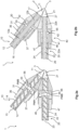
- the longitudinal axes 13 and 23 of the extruders 10, 20 converge towards the extrusion head 2 and are located in the axis of symmetry thereof (configuration of the type illustrated in Fig. 3a and 3b ).
- the outlet ports 17, respectively 27 of the extruders 10, 20, open directly into the flow channels 11, 21 of the extrusion head 2.
- This embodiment makes it possible to relocate the piston pump of each extruder upstream of the extrusion head for a smaller footprint of the installation.
- axial piston pumps are provided having a similar construction, but arranged beyond the mixture outlet.
- the piston pump axial 30, 40 is placed so that the inlet chambers 53, 63 open into a discharge orifice 56, 66 located at a distance of between 1/3 and 1 ⁇ 2 of the length of the extrusion screw 12, 22 as measured from the outlet orifice 17, 27 thereof.
- the distribution member 55, respectively 65 is carried by the extrusion screw 12, 22 while being located in a notch provided for this purpose along the length of the screw.
- This variant also has the advantage of a very compact construction, with reduced space requirements. It is thus possible to arrange several extruders side by side juxtaposed vertically and which feed the flow channels of a common extrusion head.
- FIGS. 3a to 3c illustrate examples of coextrusion installations according to the invention using several extruders which deliver a complex coextruded product into an extrusion head.
- Installation 1a of the Figure 3a illustrates an arrangement of several extruders all arranged in the plane of symmetry of the extrusion head 2.
- Each extruder 10, 20, m, n is a volumetric extruder, the extrusion screw of each extruder constituting the feeding element of an axial piston pump, as previously described.
- Installation 1b of the figure 3b illustrates an arrangement of several extruders arranged on either side of the plane of symmetry of the extrusion head 2.
- Each extruder 10, 20, m, n is a volumetric extruder, the extrusion screw of each extruder constituting the feeding element of an axial piston pump, as previously described.
- the 1c installation of the figure 3c illustrates an arrangement of several extruders arranged side by side and on either side of the plane of symmetry of the extrusion head 2.
- Each extruder 10, 20, m, n is a volumetric extruder, the extrusion screw of each extruder constituting the feeding element of an axial piston pump, as previously described.
- At least two additional extruders 10', 20' are arranged with the longitudinal axes 13', 23' in the same plane P which intersects the plane of symmetry of the extrusion head 2. It is arranged so that the two extruders 10', 20' discharge into flow channels which are in the plane defined by the axes 13', 23' for an optimized size of the extruders.
- This variant illustrated in the figure 3b also applies in combination with the arrangements illustrated in Figures 3a and 3c .
- At least two of the extruders 10, 20, m, n deliver the same mixture of elastomers (of the same composition).
- the installation comprises a control unit which is capable of adjusting the rotation speed of the screws 12, 22 of the extruders 10, 20 and that of the drive cam of the axial pistons of each pump, in particular as a function of the dimensions of the coextruded profile and the rheological properties of the materials transported.
- the control unit actuates, depending on the desired dimensions of the coextruded complex profile or depending on the operating regime (variable speed, start and stop conditions) the speed of the geared motors driving the extrusion screws.
- the rotation speed of the cam actuating the pistons of the axial piston pump is directly proportional to the variation in the flow rate. This allows the control unit to adjust the flow rate provided by the distributor member within each extruder 10, 20 depending on the dimensions of the coextruded product and also to keep it constant during operation.
- the dimensions of the coextruded complex profile are pre-established and measured using an optical sensor located in extrusion head outlet 2.
- the sensor checks the dimensions of the coextruded profile and its conformity with pre-established dimensions by being connected to the control unit.
- a weight sensor measures the weight of the coextruded profile and is connected to the control unit, which thus adjusts the tolerances of the coextruded product even more finely.
- control unit is also connected to the means for pulling the coextruded profile strip to adjust its speed.
- the control of the piston pumps and that of the extruders makes it possible to provide a constant and measurable flow of material at the outlet of the plant, and therefore a volumetric extrusion on each lane.
- the extrudates arriving at the outlet of each extruder are sent under pressure and without mixing into the channels 11, 12 of the die 2 to thus obtain a coextruded profile.
- the axial piston pump has a different number of pistons than those in the illustrated examples.
- the pump has a single piston and a single metering chamber.
- the pump has four pistons that fill four metering chambers.
- a single geared motor drives the pistons of the axial piston pump and the screw of the feed extruder.
- the piston pump is a radial piston pump.
Landscapes
- Engineering & Computer Science (AREA)
- Mechanical Engineering (AREA)
- General Engineering & Computer Science (AREA)
- Extrusion Moulding Of Plastics Or The Like (AREA)
Claims (10)
- Anlage (1) zur Koextrusion, um ein komplexes Profil für Reifen herzustellen, das auf Basis von Kautschukmischungen mit unterschiedlichen Zusammensetzungen ausgeführt ist, wobei die Anlage einen Extrusionskopf (2) umfasst sowie mindestens einen ersten Extruder (10), der eine Schnecke (12) mit einer Längsachse (13) umfasst sowie einen Zylinder (14) zur Aufnahme der Schnecke (12), der einen Zuführeinlass (16) zum Zuführen einer Kautschukmischung umfasst und einen Auslass (17), der in einen Auslaufkanal (11) mündet, der den Auslass (17) mit dem Extrusionskopf (2) verbindet, wobei die Anlage auch mindestens einen zweiten Extruder (20) umfasst, der eine Schnecke (22) mit einer Längsachse (23) umfasst sowie einen Zylinder (24) zur Aufnahme der Schnecke (22), der einen Zuführeinlass (26) zum Zuführen einer Kautschukmischung umfasst und einen Auslass (27), der in einen Auslaufkanal (21) mündet, der den Auslass (27) mit dem Extrusionskopf (2) verbindet, wobei die Anlage dadurch gekennzeichnet ist, dass die Schnecke (12, 22) jedes Extruders (10, 20) das Speiseelement einer Verdrängerkolbenpumpe (30, 40) darstellt, die einen oder mehrere Kolben umfasst, die die Kautschukmischungsmenge dosiert, die in jeden Auslaufkanal (11, 21) geleitet wird, der den Extruder (10, 20) mit dem Extrusionskopf verbindet, und die stromauf des Auslasses (17, 27) des Extruders (10, 20) angeordnet ist, so dass man einen ersten Teil (12a, 22a) der Länge der Schnecke (12, 22) des Extruders (10, 20), ausgehend von dem Zuführeinlass (16, 26), dazu verwenden kann, die Kautschukmischung zu verflüssigen und auf Temperatur zu bringen, während der restliche Teil (12b, 22b) der Länge der Schnecke (12, 22) des Extruders (10, 20) dazu verwendet wird, die von der Verdrängerkolbenpumpe (30, 40) dosierte Kautschukmischung zu den Auslaufkanälen (11, 21) zu befördern, die den Auslass (17, 27) des Extruders (10, 20) mit dem Extrusionskopf verbinden.
- Anlage nach Anspruch 1, dadurch gekennzeichnet, dass die Verdrängerkolbenpumpe (30, 40) eine Pumpe ist, die zwei axiale Kolben (36, 37, 46, 47) mit Achsen umfasst, die parallel zu der Längsachse (13, 23) des Extruders sind.
- Anlage nach Anspruch 2, dadurch gekennzeichnet, dass die Verdrängerkolbenpumpe (30, 40) ein Pumpengehäuse (31, 41) aufweist, das eine Kammer (32, 42) zur Druckbeaufschlagung der Kautschukmischung begrenzt, wobei die Verdrängerkolbenpumpe (30, 40) auch eine erste Dosierkammer (33, 43) und eine zweite Dosierkammer (34, 44) aufweist, in denen die Kolben (36, 37, 46, 47) zwischen einem oberen Totpunkt (PMH), der einer Phase des Förderns der Kautschukmischung aus der Dosierkammer (33, 43, 34, 44) entspricht, und einem unteren Totpunkt (PMB), der einer Phase des Einlassens der Kautschukmischung in die Dosierkammer entspricht, verschieblich sind, wobei die ersten und zweiten Dosierkammern (33, 43, 34, 44) mit der Kammer (32, 42) zur Druckbeaufschlagung dank von Verbindungsöffnungen (35, 45) zusammenwirken und in eine Einlasskammer (53, 63) eines Verteilorgans (55, 65) münden, wobei das Verteilorgan (55, 65) von der Schnecke (12, 22) des Extruders (10, 20) getragen wird, so dass das Verteilorgan (55, 65) um die Längsachse (13, 23) herum drehbeweglich ist zwischen einer Stellung des Förderns der Kautschukmischung der betrachteten Dosierkammer (33, 34, 43, 44), die der oberen Totpunktstellung (PMH) des Kolbens entspricht, und einer Stellung des Einlassens der Kautschukmischung in die Dosierkammer (33, 34, 43, 44), die der unteren Totpunktstellung (PMB) des Kolbens entspricht, und dadurch, dass die Einlasskammern (53, 63) des Verteilorgans (55, 65) in eine Förderöffnung (56, 66) münden, die in einem Abstand zwischen 1/3 und ½ der Länge der Extrusionsschnecke (12, 22), gemessen ab dem Auslass (17, 27), gelegen ist.
- Anlage (1) nach einem der Ansprüche 1 bis 3, dadurch gekennzeichnet, dass die Achsen (13, 23) der Extruder (10, 20) einen spitzen Winkel untereinander bilden.
- Anlage nach einem der vorhergehenden Ansprüche, dadurch gekennzeichnet, dass die Achsen (13, 23) der Extruder (10, 20) jeweils in einer vertikalen oder in Bezug auf eine vertikale Ebene geneigten Ebene angeordnet sind.
- Anlage nach einem der Ansprüche 1 bis 5, dadurch gekennzeichnet, dass sie eine Steuerungseinheit umfasst, die die Drehzahl der Schnecke (12, 22) mit der Frequenz der Hin- und Her-Bewegung der Kolben der Kolbenpumpe synchronisiert.
- Unterbaugruppe für eine Anlage nach einem der Ansprüche 1 bis 6, wobei die Unterbaugruppe einen Extruder (10) aufweist, der eine Schnecke (12) mit einer Längsachse (13) umfasst sowie einen Zylinder (14) zur Aufnahme der Schnecke (12), der einen Zuführeinlass (16) zum Zuführen von Kautschukmischung umfasst und einen Auslass (17), der dazu bestimmt ist, in einen Auslaufkanal (11) zu münden, wobei die Unterbaugruppe dadurch gekennzeichnet ist, dass die Schnecke (12) des Extruders (10) das Speiseelement einer Verdrängerkolbenpumpe (30) darstellt, die einen oder mehrere Kolben umfasst, die dazu bestimmt ist, die Kautschukmischungsmenge zu dosieren, die in den Auslaufkanal (11) geleitet wird, und die stromauf des Auslasses (17) des Extruders (10) angeordnet ist, so dass man einen ersten Teil (12a, 22a) der Länge der Schnecke (12) des Extruders (10), ausgehend von dem Zuführeinlass (16), dazu verwenden kann, die Kautschukmischung zu verflüssigen und auf Temperatur zu bringen, während der restliche Teil (12b) der Länge der Schnecke (12) des Extruders (10) dazu verwendet wird, die von der Verdrängerkolbenpumpe (30) dosierte Kautschukmischung zu dem Auslaufkanal (11) zu befördern, der mit dem Auslass (17) des Extruders (10) verbunden ist.
- Unterbaugruppe nach Anspruch 7, dadurch gekennzeichnet, dass die Verdrängerkolbenpumpe (30) eine Pumpe ist, die zwei axiale Kolben (36, 37) mit zur Längsachse (13) des Extruders (10) parallelen Achsen umfasst, dass die Verdrängerkolbenpumpe (30) ein Pumpengehäuse (31) aufweist, das eine Kammer (32) zur Druckbeaufschlagung der Kautschukmischung begrenzt, wobei die Verdrängerkolbenpumpe (30) auch eine erste Dosierkammer (33) und eine zweite Dosierkammer (34) aufweist, in denen die Kolben (36, 37) zwischen einem oberen Totpunkt (PMH), der einer Phase des Förderns der Kautschukmischung aus der Dosierkammer (33, 43) entspricht, und einem unteren Totpunkt (PMB), der einer Phase des Einlassens der Kautschukmischung in die Dosierkammer entspricht, verschieblich sind, wobei die ersten und zweiten Dosierkammern (33, 34) mit der Kammer (32) zur Druckbeaufschlagung dank von Verbindungsöffnungen (35) zusammenwirken und in eine Einlasskammer (53) eines Verteilorgans (55) münden, wobei das Verteilorgan (55) von der Schnecke (12) des Extruders (10) getragen wird, so dass das Verteilorgan (55) um die Längsachse (13) herum drehbeweglich ist zwischen einer Stellung des Förderns der Kautschukmischung der betrachteten Dosierkammer (33, 34), die der oberen Totpunktstellung (PMH) des Kolbens entspricht, und einer Stellung des Einlassens der Kautschukmischung in die Dosierkammer (33, 34), die der unteren Totpunktstellung (PMB) des Kolbens entspricht, und dass die Einlasskammer (53) des Verteilorgans (55) in eine Förderöffnung (56) mündet, die in einem Abstand zwischen 1/3 und ½ der Länge der Extrusionsschnecke (12), gemessen ab dem Auslass (17), gelegen ist.
- Verfahren zur Koextrusion, um ein komplexes Profil für Reifen herzustellen, das auf Basis von Kautschukmischungen mit unterschiedlichen Zusammensetzungen ausgeführt ist, umfassend mindestens einen ersten Extruder (10), der eine Schnecke (12) mit einer Längsachse (13) umfasst, und mindestens einen zweiten Extruder (20), der eine Schnecke (22) mit einer Längsachse (23) umfasst, und einen Extrusionskopf (2), der mit dem Auslass (17, 27) jedes der Extruder durch geeignete Auslaufkanäle (11, 21) verbunden ist, dadurch gekennzeichnet, dass die Schnecke jedes Extruders (10, 20) das Speiseelement für Elastomermischung einer Kolbenpumpe (30, 40) ist, die stromauf des Auslasses (17, 27) des Extruders (10, 20) angeordnet ist, so dass man einen ersten Teil (12a, 22a) der Länge der Schnecke (12, 22) des Extruders (10, 20) dazu verwendet, die Kautschukmischung zu verflüssigen und auf Temperatur zu bringen, man die Kautschukmischung mittels der Verdrängerkolbenpumpe (30, 40) dosiert und man den restlichen Teil (12b, 22b) der Länge der Schnecke (12, 22) des Extruders (10, 20) dazu verwendet, die von der Verdrängerkolbenpumpe (30, 40) dosierte Kautschukmischung zu den Auslaufkanälen (11, 21) zu befördern, die den Auslass (17, 27) des Extruders (10, 20) mit dem Extrusionskopf verbinden.
- Verfahren nach Anspruch 9, dadurch gekennzeichnet, dass man die Drehzahl der Schnecke (12, 22) mit der Frequenz der Wechselbewegung der Kolben der Kolbenpumpe (30, 40) synchronisiert.
Applications Claiming Priority (2)
| Application Number | Priority Date | Filing Date | Title |
|---|---|---|---|
| FR1755716A FR3067967A1 (fr) | 2017-06-22 | 2017-06-22 | Installation et procede de coextrusion |
| PCT/FR2018/051513 WO2018234712A1 (fr) | 2017-06-22 | 2018-06-21 | Installation et procede de coextrusion |
Publications (2)
| Publication Number | Publication Date |
|---|---|
| EP3642004A1 EP3642004A1 (de) | 2020-04-29 |
| EP3642004B1 true EP3642004B1 (de) | 2024-10-30 |
Family
ID=59859259
Family Applications (1)
| Application Number | Title | Priority Date | Filing Date |
|---|---|---|---|
| EP18749441.4A Active EP3642004B1 (de) | 2017-06-22 | 2018-06-21 | Anlage, unterbaugruppe und verfahren zur koextrusion |
Country Status (3)
| Country | Link |
|---|---|
| EP (1) | EP3642004B1 (de) |
| FR (1) | FR3067967A1 (de) |
| WO (1) | WO2018234712A1 (de) |
Families Citing this family (2)
| Publication number | Priority date | Publication date | Assignee | Title |
|---|---|---|---|---|
| FR3117398B1 (fr) * | 2020-12-16 | 2023-10-06 | Continental Reifen Deutschland Gmbh | Installation d’extrusion améliorée pour la fabrication de bande de profilé |
| FR3156171B1 (fr) * | 2023-11-30 | 2025-10-24 | Michelin & Cie | Pompe volumétrique à pression régulée |
Citations (1)
| Publication number | Priority date | Publication date | Assignee | Title |
|---|---|---|---|---|
| FR2381616A1 (fr) * | 1977-02-25 | 1978-09-22 | Dechavanne Jacques | Unite d'injection universelle pour matieres thermoplastiques, thermodurcissables et elastomeres |
Family Cites Families (12)
| Publication number | Priority date | Publication date | Assignee | Title |
|---|---|---|---|---|
| US4005167A (en) * | 1967-07-28 | 1977-01-25 | Imperial Chemical Industries Limited | Plasticizing apparatus |
| DE2601815A1 (de) * | 1975-03-05 | 1976-09-16 | Ishikawajima Harima Heavy Ind | Verfahren und vorrichtung zur blasformung von werkstoffen aus hitzehaertenden hochmolekularen verbindungen |
| JPH0617056B2 (ja) * | 1986-12-18 | 1994-03-09 | 鬼怒川ゴム工業株式会社 | エアダクトの製造装置 |
| FR2647852A1 (fr) | 1989-06-01 | 1990-12-07 | Michelin & Cie | Pompe volumetrique pour matiere pateuse |
| JP2847998B2 (ja) * | 1991-03-28 | 1999-01-20 | 豊田合成株式会社 | ブロー成形機 |
| JPH07148825A (ja) * | 1993-11-30 | 1995-06-13 | Aisin Seiki Co Ltd | 押出成形用可変量押出装置 |
| FR2721662A1 (fr) | 1994-06-28 | 1995-12-29 | Sedepro | Pompe volumétrique à boisseau. |
| CN1564733A (zh) * | 2001-08-16 | 2005-01-12 | Ispa股份有限公司 | 挤出复合物挤压注射方法和装置 |
| FR2944837B1 (fr) * | 2009-04-24 | 2016-06-03 | Soc De Tech Michelin | Pompe volumetrique comprenant un absorbeur de pression |
| CN102173056B (zh) * | 2010-12-30 | 2014-09-03 | 联塑(杭州)机械有限公司 | 形成发泡产品的方法及其系统 |
| CN102173042B (zh) | 2011-02-17 | 2013-07-24 | 桂林橡胶设计院有限公司 | 侧面锁紧复合橡胶挤出机头 |
| DE102013109346A1 (de) | 2013-08-29 | 2015-03-05 | Continental Reifen Deutschland Gmbh | Verfahren zur Herstellung von Vormaterial für Fahrzeugreifen |
-
2017
- 2017-06-22 FR FR1755716A patent/FR3067967A1/fr not_active Ceased
-
2018
- 2018-06-21 WO PCT/FR2018/051513 patent/WO2018234712A1/fr not_active Ceased
- 2018-06-21 EP EP18749441.4A patent/EP3642004B1/de active Active
Patent Citations (1)
| Publication number | Priority date | Publication date | Assignee | Title |
|---|---|---|---|---|
| FR2381616A1 (fr) * | 1977-02-25 | 1978-09-22 | Dechavanne Jacques | Unite d'injection universelle pour matieres thermoplastiques, thermodurcissables et elastomeres |
Also Published As
| Publication number | Publication date |
|---|---|
| FR3067967A1 (fr) | 2018-12-28 |
| EP3642004A1 (de) | 2020-04-29 |
| WO2018234712A1 (fr) | 2018-12-27 |
Similar Documents
| Publication | Publication Date | Title |
|---|---|---|
| EP3393750B1 (de) | Vorrichtung und verfahren zum extrudieren von kautschukmischungen | |
| FR2698820A1 (fr) | Procédé et appareil de mélangeage en continu de caoutchouc. | |
| CA1327683C (fr) | Procede de fabrication d'un pneumatique avec pose des produits caoutchouteux sur un support ferme, dispositif de pose selon un tel procede, machine utilisant de tels dispositifs | |
| EP3642004B1 (de) | Anlage, unterbaugruppe und verfahren zur koextrusion | |
| FR2490995A1 (fr) | Dispositif de transformation, du type extrudeuse, pour obtenir des produits intermediares, tels que bandes, granules, a partir de melanges pulverulents de caoutchouc | |
| EP3538342B1 (de) | Anordnung zur volumetrischen extrusion für elastomermischungen | |
| EP3642003B1 (de) | Anlage und verfahren zur koextrusion | |
| EP3558625B1 (de) | Extrusionsanlage mit einem verbesserten extrusionskopf | |
| EP3853001A1 (de) | Koextrusionsmaschine für elastomere verbindungen und verfahren zur herstellung einer profilelementeleiste | |
| EP3162533B1 (de) | Anlage für die herstellung einer wärmeschutzverkleidung eines körpers oder einer rückwärtigen einheit eines triebwerks, und entsprechende verfahren | |
| EP4638089A1 (de) | Miniaturisierter volumetrischer extruder mit zwei konischen schrauben, von denen jedes mit einem gewinde versehen ist, dessen ganghöhe die aufrechterhaltung einer konstanten verdrängung erhöht | |
| EP3558624A1 (de) | Extrusionsausrüstung mit verbessertem extruderkopf | |
| WO2019193288A1 (fr) | Installation d'extrusion pour bandes de profiles realisees a base de melanges elastomeriques | |
| FR3084844A1 (fr) | Installation d'extrusion pour bande de profiles en melanges elastomeriques | |
| FR3163887A1 (fr) | Extrudeuse volumétrique miniaturisée utilisant des vis coniques jumelées formant un étage d’alimentation suivi d’un étage volumetrique | |
| FR3057197A1 (fr) | Extrudeuse et procede d'extrusion d'un melange d'elastomeres | |
| WO2018104630A1 (fr) | Extrudeuse a doigts mobiles et procede | |
| HU181502B (hu) | Homogenizáló fröccs-csiga, fröccsöntőgépekhez |
Legal Events
| Date | Code | Title | Description |
|---|---|---|---|
| STAA | Information on the status of an ep patent application or granted ep patent |
Free format text: STATUS: UNKNOWN |
|
| STAA | Information on the status of an ep patent application or granted ep patent |
Free format text: STATUS: THE INTERNATIONAL PUBLICATION HAS BEEN MADE |
|
| PUAI | Public reference made under article 153(3) epc to a published international application that has entered the european phase |
Free format text: ORIGINAL CODE: 0009012 |
|
| STAA | Information on the status of an ep patent application or granted ep patent |
Free format text: STATUS: REQUEST FOR EXAMINATION WAS MADE |
|
| 17P | Request for examination filed |
Effective date: 20200122 |
|
| AK | Designated contracting states |
Kind code of ref document: A1 Designated state(s): AL AT BE BG CH CY CZ DE DK EE ES FI FR GB GR HR HU IE IS IT LI LT LU LV MC MK MT NL NO PL PT RO RS SE SI SK SM TR |
|
| AX | Request for extension of the european patent |
Extension state: BA ME |
|
| DAV | Request for validation of the european patent (deleted) | ||
| DAX | Request for extension of the european patent (deleted) | ||
| STAA | Information on the status of an ep patent application or granted ep patent |
Free format text: STATUS: EXAMINATION IS IN PROGRESS |
|
| 17Q | First examination report despatched |
Effective date: 20220222 |
|
| REG | Reference to a national code |
Ref country code: DE Ref legal event code: R079 Free format text: PREVIOUS MAIN CLASS: B29C0047560000 Ipc: B29C0048160000 Ref country code: DE Ref legal event code: R079 Ref document number: 602018075986 Country of ref document: DE Free format text: PREVIOUS MAIN CLASS: B29C0047560000 Ipc: B29C0048160000 |
|
| GRAP | Despatch of communication of intention to grant a patent |
Free format text: ORIGINAL CODE: EPIDOSNIGR1 |
|
| STAA | Information on the status of an ep patent application or granted ep patent |
Free format text: STATUS: GRANT OF PATENT IS INTENDED |
|
| RIC1 | Information provided on ipc code assigned before grant |
Ipc: F04B 1/18 20060101ALN20240430BHEP Ipc: F04B 7/00 20060101ALN20240430BHEP Ipc: B29C 48/475 20190101ALI20240430BHEP Ipc: B29C 48/49 20190101ALI20240430BHEP Ipc: B29C 48/16 20190101AFI20240430BHEP |
|
| INTG | Intention to grant announced |
Effective date: 20240522 |
|
| GRAS | Grant fee paid |
Free format text: ORIGINAL CODE: EPIDOSNIGR3 |
|
| GRAA | (expected) grant |
Free format text: ORIGINAL CODE: 0009210 |
|
| STAA | Information on the status of an ep patent application or granted ep patent |
Free format text: STATUS: THE PATENT HAS BEEN GRANTED |
|
| AK | Designated contracting states |
Kind code of ref document: B1 Designated state(s): AL AT BE BG CH CY CZ DE DK EE ES FI FR GB GR HR HU IE IS IT LI LT LU LV MC MK MT NL NO PL PT RO RS SE SI SK SM TR |
|
| REG | Reference to a national code |
Ref country code: GB Ref legal event code: FG4D Free format text: NOT ENGLISH |
|
| REG | Reference to a national code |
Ref country code: CH Ref legal event code: EP |
|
| REG | Reference to a national code |
Ref country code: IE Ref legal event code: FG4D Free format text: LANGUAGE OF EP DOCUMENT: FRENCH |
|
| REG | Reference to a national code |
Ref country code: DE Ref legal event code: R096 Ref document number: 602018075986 Country of ref document: DE |
|
| REG | Reference to a national code |
Ref country code: LT Ref legal event code: MG9D |
|
| REG | Reference to a national code |
Ref country code: NL Ref legal event code: MP Effective date: 20241030 |
|
| PG25 | Lapsed in a contracting state [announced via postgrant information from national office to epo] |
Ref country code: PT Free format text: LAPSE BECAUSE OF FAILURE TO SUBMIT A TRANSLATION OF THE DESCRIPTION OR TO PAY THE FEE WITHIN THE PRESCRIBED TIME-LIMIT Effective date: 20250228 Ref country code: IS Free format text: LAPSE BECAUSE OF FAILURE TO SUBMIT A TRANSLATION OF THE DESCRIPTION OR TO PAY THE FEE WITHIN THE PRESCRIBED TIME-LIMIT Effective date: 20250228 Ref country code: HR Free format text: LAPSE BECAUSE OF FAILURE TO SUBMIT A TRANSLATION OF THE DESCRIPTION OR TO PAY THE FEE WITHIN THE PRESCRIBED TIME-LIMIT Effective date: 20241030 |
|
| PG25 | Lapsed in a contracting state [announced via postgrant information from national office to epo] |
Ref country code: FI Free format text: LAPSE BECAUSE OF FAILURE TO SUBMIT A TRANSLATION OF THE DESCRIPTION OR TO PAY THE FEE WITHIN THE PRESCRIBED TIME-LIMIT Effective date: 20241030 Ref country code: NL Free format text: LAPSE BECAUSE OF FAILURE TO SUBMIT A TRANSLATION OF THE DESCRIPTION OR TO PAY THE FEE WITHIN THE PRESCRIBED TIME-LIMIT Effective date: 20241030 |
|
| REG | Reference to a national code |
Ref country code: AT Ref legal event code: MK05 Ref document number: 1736501 Country of ref document: AT Kind code of ref document: T Effective date: 20241030 |
|
| PG25 | Lapsed in a contracting state [announced via postgrant information from national office to epo] |
Ref country code: BG Free format text: LAPSE BECAUSE OF FAILURE TO SUBMIT A TRANSLATION OF THE DESCRIPTION OR TO PAY THE FEE WITHIN THE PRESCRIBED TIME-LIMIT Effective date: 20241030 |
|
| PG25 | Lapsed in a contracting state [announced via postgrant information from national office to epo] |
Ref country code: ES Free format text: LAPSE BECAUSE OF FAILURE TO SUBMIT A TRANSLATION OF THE DESCRIPTION OR TO PAY THE FEE WITHIN THE PRESCRIBED TIME-LIMIT Effective date: 20241030 |
|
| PG25 | Lapsed in a contracting state [announced via postgrant information from national office to epo] |
Ref country code: NO Free format text: LAPSE BECAUSE OF FAILURE TO SUBMIT A TRANSLATION OF THE DESCRIPTION OR TO PAY THE FEE WITHIN THE PRESCRIBED TIME-LIMIT Effective date: 20250130 |
|
| PG25 | Lapsed in a contracting state [announced via postgrant information from national office to epo] |
Ref country code: LV Free format text: LAPSE BECAUSE OF FAILURE TO SUBMIT A TRANSLATION OF THE DESCRIPTION OR TO PAY THE FEE WITHIN THE PRESCRIBED TIME-LIMIT Effective date: 20241030 Ref country code: AT Free format text: LAPSE BECAUSE OF FAILURE TO SUBMIT A TRANSLATION OF THE DESCRIPTION OR TO PAY THE FEE WITHIN THE PRESCRIBED TIME-LIMIT Effective date: 20241030 Ref country code: GR Free format text: LAPSE BECAUSE OF FAILURE TO SUBMIT A TRANSLATION OF THE DESCRIPTION OR TO PAY THE FEE WITHIN THE PRESCRIBED TIME-LIMIT Effective date: 20250131 |
|
| PG25 | Lapsed in a contracting state [announced via postgrant information from national office to epo] |
Ref country code: PL Free format text: LAPSE BECAUSE OF FAILURE TO SUBMIT A TRANSLATION OF THE DESCRIPTION OR TO PAY THE FEE WITHIN THE PRESCRIBED TIME-LIMIT Effective date: 20241030 |
|
| PG25 | Lapsed in a contracting state [announced via postgrant information from national office to epo] |
Ref country code: RS Free format text: LAPSE BECAUSE OF FAILURE TO SUBMIT A TRANSLATION OF THE DESCRIPTION OR TO PAY THE FEE WITHIN THE PRESCRIBED TIME-LIMIT Effective date: 20250130 |
|
| PG25 | Lapsed in a contracting state [announced via postgrant information from national office to epo] |
Ref country code: SM Free format text: LAPSE BECAUSE OF FAILURE TO SUBMIT A TRANSLATION OF THE DESCRIPTION OR TO PAY THE FEE WITHIN THE PRESCRIBED TIME-LIMIT Effective date: 20241030 |
|
| PGFP | Annual fee paid to national office [announced via postgrant information from national office to epo] |
Ref country code: DE Payment date: 20250618 Year of fee payment: 8 |
|
| PG25 | Lapsed in a contracting state [announced via postgrant information from national office to epo] |
Ref country code: DK Free format text: LAPSE BECAUSE OF FAILURE TO SUBMIT A TRANSLATION OF THE DESCRIPTION OR TO PAY THE FEE WITHIN THE PRESCRIBED TIME-LIMIT Effective date: 20241030 |
|
| PG25 | Lapsed in a contracting state [announced via postgrant information from national office to epo] |
Ref country code: EE Free format text: LAPSE BECAUSE OF FAILURE TO SUBMIT A TRANSLATION OF THE DESCRIPTION OR TO PAY THE FEE WITHIN THE PRESCRIBED TIME-LIMIT Effective date: 20241030 |
|
| PGFP | Annual fee paid to national office [announced via postgrant information from national office to epo] |
Ref country code: FR Payment date: 20250626 Year of fee payment: 8 |
|
| PG25 | Lapsed in a contracting state [announced via postgrant information from national office to epo] |
Ref country code: RO Free format text: LAPSE BECAUSE OF FAILURE TO SUBMIT A TRANSLATION OF THE DESCRIPTION OR TO PAY THE FEE WITHIN THE PRESCRIBED TIME-LIMIT Effective date: 20241030 |
|
| PG25 | Lapsed in a contracting state [announced via postgrant information from national office to epo] |
Ref country code: SK Free format text: LAPSE BECAUSE OF FAILURE TO SUBMIT A TRANSLATION OF THE DESCRIPTION OR TO PAY THE FEE WITHIN THE PRESCRIBED TIME-LIMIT Effective date: 20241030 |
|
| PG25 | Lapsed in a contracting state [announced via postgrant information from national office to epo] |
Ref country code: CZ Free format text: LAPSE BECAUSE OF FAILURE TO SUBMIT A TRANSLATION OF THE DESCRIPTION OR TO PAY THE FEE WITHIN THE PRESCRIBED TIME-LIMIT Effective date: 20241030 |
|
| PG25 | Lapsed in a contracting state [announced via postgrant information from national office to epo] |
Ref country code: IT Free format text: LAPSE BECAUSE OF FAILURE TO SUBMIT A TRANSLATION OF THE DESCRIPTION OR TO PAY THE FEE WITHIN THE PRESCRIBED TIME-LIMIT Effective date: 20241030 |
|
| REG | Reference to a national code |
Ref country code: DE Ref legal event code: R097 Ref document number: 602018075986 Country of ref document: DE |
|
| PLBE | No opposition filed within time limit |
Free format text: ORIGINAL CODE: 0009261 |
|
| STAA | Information on the status of an ep patent application or granted ep patent |
Free format text: STATUS: NO OPPOSITION FILED WITHIN TIME LIMIT |
|
| PG25 | Lapsed in a contracting state [announced via postgrant information from national office to epo] |
Ref country code: SE Free format text: LAPSE BECAUSE OF FAILURE TO SUBMIT A TRANSLATION OF THE DESCRIPTION OR TO PAY THE FEE WITHIN THE PRESCRIBED TIME-LIMIT Effective date: 20241030 |
|
| 26N | No opposition filed |
Effective date: 20250731 |
|
| REG | Reference to a national code |
Ref country code: CH Ref legal event code: H13 Free format text: ST27 STATUS EVENT CODE: U-0-0-H10-H13 (AS PROVIDED BY THE NATIONAL OFFICE) Effective date: 20260127 |
|
| PG25 | Lapsed in a contracting state [announced via postgrant information from national office to epo] |
Ref country code: MC Free format text: LAPSE BECAUSE OF FAILURE TO SUBMIT A TRANSLATION OF THE DESCRIPTION OR TO PAY THE FEE WITHIN THE PRESCRIBED TIME-LIMIT Effective date: 20241030 |
|
| PG25 | Lapsed in a contracting state [announced via postgrant information from national office to epo] |
Ref country code: LU Free format text: LAPSE BECAUSE OF NON-PAYMENT OF DUE FEES Effective date: 20250621 |
|
| GBPC | Gb: european patent ceased through non-payment of renewal fee |
Effective date: 20250621 |
|
| REG | Reference to a national code |
Ref country code: BE Ref legal event code: MM Effective date: 20250630 |
|
| PG25 | Lapsed in a contracting state [announced via postgrant information from national office to epo] |
Ref country code: GB Free format text: LAPSE BECAUSE OF NON-PAYMENT OF DUE FEES Effective date: 20250621 |
|
| PG25 | Lapsed in a contracting state [announced via postgrant information from national office to epo] |
Ref country code: IE Free format text: LAPSE BECAUSE OF NON-PAYMENT OF DUE FEES Effective date: 20250621 |
|
| PG25 | Lapsed in a contracting state [announced via postgrant information from national office to epo] |
Ref country code: BE Free format text: LAPSE BECAUSE OF NON-PAYMENT OF DUE FEES Effective date: 20250630 |
|
| PG25 | Lapsed in a contracting state [announced via postgrant information from national office to epo] |
Ref country code: CH Free format text: LAPSE BECAUSE OF NON-PAYMENT OF DUE FEES Effective date: 20250630 |