EP3641105A1 - Gleichstrommotor und verfahren zu seiner herstellung - Google Patents
Gleichstrommotor und verfahren zu seiner herstellung Download PDFInfo
- Publication number
- EP3641105A1 EP3641105A1 EP19201048.6A EP19201048A EP3641105A1 EP 3641105 A1 EP3641105 A1 EP 3641105A1 EP 19201048 A EP19201048 A EP 19201048A EP 3641105 A1 EP3641105 A1 EP 3641105A1
- Authority
- EP
- European Patent Office
- Prior art keywords
- stator
- motor
- contact
- winding
- motor according
- Prior art date
- Legal status (The legal status is an assumption and is not a legal conclusion. Google has not performed a legal analysis and makes no representation as to the accuracy of the status listed.)
- Granted
Links
- 238000000034 method Methods 0.000 title claims abstract description 47
- 238000004519 manufacturing process Methods 0.000 title claims abstract description 16
- 238000004804 winding Methods 0.000 claims abstract description 72
- 239000011810 insulating material Substances 0.000 claims description 30
- 238000009413 insulation Methods 0.000 claims description 28
- 238000005452 bending Methods 0.000 claims description 19
- 238000013100 final test Methods 0.000 claims description 4
- 238000003466 welding Methods 0.000 claims description 4
- 238000003825 pressing Methods 0.000 claims description 3
- 238000005520 cutting process Methods 0.000 claims description 2
- 230000015572 biosynthetic process Effects 0.000 description 13
- 238000005755 formation reaction Methods 0.000 description 13
- 238000009434 installation Methods 0.000 description 3
- 238000000465 moulding Methods 0.000 description 2
- 210000002105 tongue Anatomy 0.000 description 2
- 238000010276 construction Methods 0.000 description 1
- 238000011161 development Methods 0.000 description 1
- 230000018109 developmental process Effects 0.000 description 1
- 230000000694 effects Effects 0.000 description 1
- 238000003475 lamination Methods 0.000 description 1
- 239000000463 material Substances 0.000 description 1
- 239000002184 metal Substances 0.000 description 1
- 239000000843 powder Substances 0.000 description 1
Images


Classifications
-
- H—ELECTRICITY
- H02—GENERATION; CONVERSION OR DISTRIBUTION OF ELECTRIC POWER
- H02K—DYNAMO-ELECTRIC MACHINES
- H02K3/00—Details of windings
- H02K3/46—Fastening of windings on the stator or rotor structure
- H02K3/52—Fastening salient pole windings or connections thereto
- H02K3/521—Fastening salient pole windings or connections thereto applicable to stators only
- H02K3/522—Fastening salient pole windings or connections thereto applicable to stators only for generally annular cores with salient poles
-
- H—ELECTRICITY
- H02—GENERATION; CONVERSION OR DISTRIBUTION OF ELECTRIC POWER
- H02K—DYNAMO-ELECTRIC MACHINES
- H02K15/00—Methods or apparatus specially adapted for manufacturing, assembling, maintaining or repairing of dynamo-electric machines
- H02K15/0056—Manufacturing winding connections
- H02K15/0068—Connecting winding sections; Forming leads; Connecting leads to terminals
-
- H—ELECTRICITY
- H02—GENERATION; CONVERSION OR DISTRIBUTION OF ELECTRIC POWER
- H02K—DYNAMO-ELECTRIC MACHINES
- H02K15/00—Methods or apparatus specially adapted for manufacturing, assembling, maintaining or repairing of dynamo-electric machines
- H02K15/08—Forming windings by laying conductors into or around core parts
- H02K15/085—Forming windings by laying conductors into or around core parts by laying conductors into slotted stators
-
- H—ELECTRICITY
- H02—GENERATION; CONVERSION OR DISTRIBUTION OF ELECTRIC POWER
- H02K—DYNAMO-ELECTRIC MACHINES
- H02K15/00—Methods or apparatus specially adapted for manufacturing, assembling, maintaining or repairing of dynamo-electric machines
- H02K15/08—Forming windings by laying conductors into or around core parts
- H02K15/095—Forming windings by laying conductors into or around core parts by laying conductors around salient poles
-
- H—ELECTRICITY
- H02—GENERATION; CONVERSION OR DISTRIBUTION OF ELECTRIC POWER
- H02K—DYNAMO-ELECTRIC MACHINES
- H02K15/00—Methods or apparatus specially adapted for manufacturing, assembling, maintaining or repairing of dynamo-electric machines
- H02K15/10—Applying solid insulation to windings, stators or rotors
- H02K15/105—Applying solid insulation to windings, stators or rotors to the windings
-
- H—ELECTRICITY
- H02—GENERATION; CONVERSION OR DISTRIBUTION OF ELECTRIC POWER
- H02K—DYNAMO-ELECTRIC MACHINES
- H02K3/00—Details of windings
- H02K3/04—Windings characterised by the conductor shape, form or construction, e.g. with bar conductors
- H02K3/28—Layout of windings or of connections between windings
-
- H—ELECTRICITY
- H02—GENERATION; CONVERSION OR DISTRIBUTION OF ELECTRIC POWER
- H02K—DYNAMO-ELECTRIC MACHINES
- H02K3/00—Details of windings
- H02K3/32—Windings characterised by the shape, form or construction of the insulation
- H02K3/34—Windings characterised by the shape, form or construction of the insulation between conductors or between conductor and core, e.g. slot insulation
- H02K3/345—Windings characterised by the shape, form or construction of the insulation between conductors or between conductor and core, e.g. slot insulation between conductor and core, e.g. slot insulation
-
- H—ELECTRICITY
- H02—GENERATION; CONVERSION OR DISTRIBUTION OF ELECTRIC POWER
- H02K—DYNAMO-ELECTRIC MACHINES
- H02K3/00—Details of windings
- H02K3/32—Windings characterised by the shape, form or construction of the insulation
- H02K3/38—Windings characterised by the shape, form or construction of the insulation around winding heads, equalising connectors, or connections thereto
-
- H—ELECTRICITY
- H02—GENERATION; CONVERSION OR DISTRIBUTION OF ELECTRIC POWER
- H02K—DYNAMO-ELECTRIC MACHINES
- H02K2203/00—Specific aspects not provided for in the other groups of this subclass relating to the windings
- H02K2203/09—Machines characterised by wiring elements other than wires, e.g. bus rings, for connecting the winding terminations
-
- H—ELECTRICITY
- H02—GENERATION; CONVERSION OR DISTRIBUTION OF ELECTRIC POWER
- H02K—DYNAMO-ELECTRIC MACHINES
- H02K2203/00—Specific aspects not provided for in the other groups of this subclass relating to the windings
- H02K2203/12—Machines characterised by the bobbins for supporting the windings
Definitions
- the invention relates to a direct current motor (1) with a permanent magnetic inner rotor (2) rotatably mounted about a motor longitudinal axis (19) and a stator (30), consisting of a wound stator core (3) with a plurality of pronounced inward poles (4). , which are integral with a return ring (5) in the circumferential direction and separated from one another by stator grooves (6), an insulating body (7) which lines the stator grooves (6) and has a return ring cover (8) which has an axial end face of the return ring (5 ), one winding wire (10) being wound continuously and without interruption successively around all poles (4) to form one coil (39) each, and the coils are connected in a triangular-parallel arrangement.
- Stator cores with pronounced poles can be one or more parts. With multi-part stator cores, the poles can be individually z. B. wrap with a flyer. The multiple interrupted magnetic circuit, however, significantly reduces the efficiency, which is why stator cores are often made in one piece in the direction of the magnetic field lines.
- One-piece stator cores can consist of a stack of sheets or of pressed metal powder; they are usually wound by a needle winder. This requires a hollow winding needle in which the winding wire is passed. The winding needle has a minimum diameter depending on the wire diameter. A minimum distance between the winding needle and stator components must also be maintained for reliable production.
- the object of the invention is therefore to provide for a generic DC motor for a compact structure, reliable production, easy assembly and good efficiency.
- the winding wire (10) forms a U-shaped wire connection (18) between two coils (39) which are spatially adjacent in the circumferential direction and which connect a first leg (51), a second leg (52) and one of the two legs (51, 52)
- Contact section (20) which is arranged axially beyond a winding head and radially a clear distance from a cylindrical envelope of the stator core (3) and the insulating body (7) does not radially enlarge the space of the stator (30), a process reliable Implementation with freely accessible contact areas and easy-to-assemble individual parts.
- the space should not be radially expanded by other components that are required for contacting the winding.
- the wire connection (18) does not run around deflecting geometries of the insulating material body (7) projecting axially or radially outward, because each additional deflection of the winding wire increases the cycle times during production and increases tool wear.
- the present invention relates in particular to DC motors in which the winding direction of coils which are spatially adjacent in the circumferential direction is in opposite directions.
- the wire connection (18) is between two spatially adjacent coil sides of two adjacent coils (39).
- the contact section (20) is arranged axially beyond the insulating body (7). As a result, the contact section (20) is easily accessible from all sides and prepared for contacting.
- an angle between one leg (51 or 52) of the wire connection (18) and the motor longitudinal axis (19) is less than or equal to 45 °, in particular less than or equal to 30 °, in particular less than or equal to 15 ° , in particular less than or equal to 10 °, in particular less than or equal to 5 °, in particular less than or equal to 2 °, in particular less than or equal to 1 °, in particular equal to 0 °.
- the distances between adjacent contacts on the one hand and opposing contacts on the other hand are larger. It is therefore preferred to align the legs (51 or 52) as parallel as possible to the longitudinal axis of the motor. This also gives the contact sections (20) a sufficient distance from a radial delimitation of a stator installation space.
- the contact section (20) of the wire connection (18) is easily accessible, it is easier to make electrical contact with a contact hook (17) of a contact unit (16). It should be noted that the contact hook (17) has a clear distance from an outer edge of the stator core (3). This configuration ensures that no radial construction beyond the stator core (3) is necessary. This enables a compact motor structure to be realized and the risk of short circuits reduced. Slight inaccuracies in the radial position of the contact sections (20) can be compensated for by the contact hooks (17).
- the contact hooks (17) lie on a reference circle (50).
- the reference circle (50) is defined by the maximum slot depth of a stator slot (6). In this position, the contact section (20) and the contact hooks (17) are sufficiently removed from a motor housing (15) and the necessary creepage distances are maintained.
- the distal end of the contact hook (17) is closed.
- the contact hooks (17) are open when they are installed trained so that they can be easily axially joined.
- the two legs of the contact hooks are advantageously not pre-shaped in parallel but in a V-shape.
- the contact unit (16) has a contact carrier (58) and a plurality of busbars (14) insulated from one another, the contact carrier (58) in the region of the return ring cover (8) with a plurality of axial stops (44) axially on the insulating material body (7 ) is present.
- the axial stops (44) form a defined contact surface.
- the contact carrier (58) can receive and align the busbars (14) in a defined position.
- the contact unit (16) is centered on the insulating body (7).
- the axial stops (44) expediently bear against axially projecting contours (56) of the insulating material body (7). These can be adapted to the axial stops (44) according to the respective requirements.
- a special feature is that several axial stops (44) protrude radially beyond the assigned contact sections (20) and are arranged axially between the assigned contact sections (20) and the insulating material body (7), in particular the axially projecting contours (56) of the insulating material body (7) .
- the wire connections (18) are bent radially outwards in an intermediate state.
- the number of contact sections (20) should correspond to the number of poles (4), one of these contact sections being formed by a winding start and a winding end of the stator winding.
- the contact sections (20) are distributed evenly over the insulating body (7) of the stator (30).
- the first leg (51) is an extension of an end turn of the coil (39) of a first pole (4), while an extension of the second leg (52) forms an initial turn of the coil of an adjacent pole.
- Another advantage of this measure is that the needle winder does not have to make tight curves and the cycle times can be relatively short.
- the invention is also characterized in that between the end turn and the first leg (51) and / or between an initial turn and the second leg (52) a first bending point (66) radially outwards and then a second bending point (67) radially to the outside is present inside.
- the first bending point (66) already occurs during needle winding, in that the wire connections are first laid radially outward, in particular diagonally outward, in order to simplify the winding of the stator.
- the winding wire (10) is first bent around an inner edge (68) of the insulating body (7).
- the second bending point (67) is axially further away from the stator core (3) and takes place around an outer edge (69) of the contact carrier (58).
- the winding wire (10) is only slightly deformed by the two bending radii.
- wire abutment surfaces (45) can be provided on the contact carrier (58), which allow the wire connections to be bent back in a defined manner. The advantages mentioned are still maintained even with slight deviations from the parallel alignment of the legs (51, 52). If there is a maximum deviation of 15 °, the axial position of the contact sections (20) changes only slightly.
- the coil end of the first pole (4) and the coil start of the second pole are arranged radially in the region of the greatest slot depth of the stator slots (6).
- the distance of the radially outer region of the contact hook (17) from the motor longitudinal axis (19) is less than the radius of the yoke ring (5).
- the yoke ring cover (8) have axially projecting contours which are radially slotted at the positions of the coil starts and coil ends, the width of the slots (55) corresponding at least to the winding wire diameter.
- guides (54) for an insulation crown (53) are formed in the protruding contours in the angular range between adjacent wire connections (18). This facilitates the spatial assignment of the components to be joined.
- the contact hook is welded to the contact section (20) of the wire connection.
- Hot staking processes or resistance welding processes are particularly suitable for this. These processes partially melt the welding partners, creating an intimate material connection and achieving a particularly low contact resistance.
- insulating means are provided which are arranged between the contact hooks (17) and the motor housing (15).
- the insulating means are cover flaps (101) which are connected to the insulating material body (7) via film hinges (100).
- the film hinges (100) are expediently aligned in the tangential direction and arranged in the region between the stator groove lining (29) and the return ring cover (8). As a result, the contact hooks can be reliably insulated from the motor housing, the cover flaps (101) being folded down during assembly and not impeding the winding process.
- the insulating means can be made in one piece with the insulation crown (53), in particular in the form of cover flaps (101).
- the insulating material body (7) can be made simpler and the cover flaps can be integral with the insulating crown (53) without film hinges.
- the invention is also achieved by a method with the following method steps: a) Provision of one provided with an insulating material body (7) Stator core (3), a motor housing (15), a contact carrier (58), insulated busbars (14), an insulation crown 53 and a bearing plate or attachment (65); b) provision of a manufacturing facility; c) inserting the stator core (3) into the manufacturing facility; d) attaching a winding wire to a stop that is fixed to the tool or workpiece; e) winding a coil around a first pole; f) leading the winding wire straight out of a stator slot with a radial and an axial component; g) laying the winding wire (10) around a winding guide contour (deflection means 60, deflection pin 62); Returning the winding wire (10) into the stator groove (6) to form a U-shaped wire connection (18); h) repeating process steps e to g until all the required coils (39) have been produced; i) attaching the winding wire (
- the winding guide contour can consist of a molding on the insulating material body (7) which is supported during the winding and which is later separated off, the support absorbing the winding tension.
- the winding guide contour can consist of tool-fixed deflection means or a combination of tool-fixed deflection means and workpiece-fixed holding means. In the latter case, the workpiece-fixed holding means temporarily hold the wire connection (18) in a defined position. Later, the holding means that are fixed to the workpiece are sheared off again.
- the contact carrier (58) is placed axially on the insulating body (7), after which radially projecting axial stops (44) bear against axially projecting contours (56) of the return ring cover (8).
- the contact carrier (58) centers itself on the inner contours of a return ring cover (8).
- the U-shaped wire connections (18) are bent in the direction of the longitudinal axis of the motor (19) while maintaining the U-shape to such an extent that the legs (51, 52) of the wire connection (18) are at least approximately parallel or slightly inclined run to the motor longitudinal axis (19).
- the legs (51, 52) are supported on axial stops (45) and Outer edges (69) of the contact carrier. This enables a defined bending process.
- the wire connections (18) are now axially in front of the axial stops (45).
- the individual busbars (14) and individual insulating elements or an assembly of busbars (14) and insulating elements are mounted on the contact carrier (58), contact hooks (17) of the busbars (14) being attached to contact sections ( 20) the wire connection (18) are placed.
- the contact hooks (17) extend radially into the area of the return ring cover (8).
- the contact hooks (17) are then intimately connected to the contact sections (20) of the wire connection (18) by means of a hot staking process or resistance welding process, a robust electrical connection with a very low contact resistance being produced.
- a permanent magnet rotor is first inserted into a motor housing (15) and only then is the stator (30) pressed into the motor housing (15).
- This sequence is necessary if a cup-shaped motor housing is available and the inside diameter of a contact unit (16) is smaller than the outside diameter of the permanent magnet rotor.
- axially continuous recesses on the insulating body (7) provided as guides (54) serve as a possibility of using a crown-like press-in tool.
- stator (30) can also be pressed in before the permanent magnet rotor (15) is installed.
- cover flaps (101) when the stator (30) is pressed into the motor housing (15), cover flaps (101) are bent from a radial original position into an axial end position and the bent cover flaps (101) are arranged between the contact unit (16) and the motor housing (15) causes.
- the cover flaps (101) are connected to the insulating material body (7) by means of film hinges (100) and serve to insulate the Wire connection (18) and especially the contact hook (17) opposite the motor housing (15).
- a further process step is characterized by the placement of an insulation crown (53) on the contact unit (16) and or the insulating material body (7).
- This process step can only take place after the stator (30) has been pressed into the motor housing (15) because the guides (54) into which the insulation crown (53) are inserted are required for the press-in tool.
- the insulation crown (53) can insulate the contact unit (16) and in particular the contact hooks (17) both axially and radially from the motor housing (15) or a bearing plate or attachment (65).
- a bearing plate or an add-on part (65), such as a pump, is mounted on the motor housing, a final test is carried out and the DC motor is removed from the production facility.
- the permanent magnet rotor is mounted only after the stator (30) has been pressed in, and then a bearing plate or an attachment (65) is fastened, a final test is carried out and the DC motor is removed from the production facility.
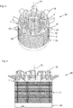
- Fig. 1 shows a first embodiment of a stator 30 of a DC motor with a first embodiment of an insulating material body 7 in a first assembly state, in which the stator 30 is already wound with a winding wire 10.
- the stator 30 consists of a stator core 3 made of layered laminations and in the present example has nine poles 4 which, starting from a return ring 5, extend radially inwards in the direction of a motor longitudinal axis 19. Between each pole 4, a wire connection 18 is made radially beyond the outer diameter of the stator core 3 and the insulating material body 7, the wire connection having an axial component and therefore being inclined by a helix angle in the direction of a winding head.
- the helix angle is selected so that a needle winding machine achieves the shortest possible cycle time and process-reliable installation is possible.
- An insulation cap is also shown on the opposite axial side of the stator core.
- the insulating material body has axially projecting guides 54.
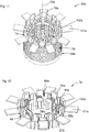
- Fig. 2 shows a sectional view of the DC motor with superimposition of the first assembly state. Shown is the stator 30 with the insulating material body 7, installed in a motor housing 15. A permanent magnetic inner rotor 2 is located opposite the poles 4. In the installed state, the wire connections 18 are in reality no longer in the assembled state Fig. 1 , but lie inside the motor housing. To illustrate the geometrical relationships during the winding process, the wire connections 18 are shown in a radial position.
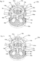
- Fig. 3 shows the stator 30 with a superposition of the first with a second assembly state.
- the wires are out of the Fig. 1 Known position shown and in addition a second layer, which occurs after a bending process, the wire connections 18 extending substantially axially parallel over the winding head 43 away from the stator core.
- the insulating material body 7 has axially projecting contours 56 which are interrupted by slots 55 through which the wire connections 18 can move during the winding process and when bending back.
- the wire connections 18 consist of a first leg 51, a second leg 52 and a contact section 20.
- the first leg 51 is an extension of an end turn of a first pole 4.
- An extension of the second leg 52 forms an initial turn of an adjacent pole.
- the stator core 3 and the insulation cap 34 and the motor longitudinal axis 19 are also shown.
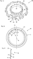
- Fig. 4 shows a front view of the stator 30 with the superimposed first and second assembly state according to Fig. 3 , with the insulating body 7, the stator core 3, the insulation cap 34, the wire connections 18 and the motor longitudinal axis.
- Fig. 5 shows the stator 30 in a second assembly state, in which the wire connections 18 are bent into an essentially axially parallel position.
- the slots 55 in the axially projecting contours 56 of the insulating body 7 no longer have a function in this state.
- the wire connections 18 are prepared for the assembly of a contact unit and have exposed and very easily accessible areas for contacting the process reliably (contact section 20).
- the length of the legs 51, 52 is dimensioned accordingly.
- the contact section 20 is straight in its central section and can thus be used over a large area as a contact surface.
- the stator core 3 the motor longitudinal axis 19 and the insulating cap 34 are shown.
- Fig. 6 shows the stator 30 in a third assembly state, with the insulation cap 34, the motor longitudinal axis, the stator core 3, the insulating body 7, wire connections 18 and a contact unit 16, consisting of three busbars 14, each with three contact projections 13, on which contact hooks 17 are formed, which are each connected to a wire connection 18, in particular to a contact section 20.
- the open side of the contact hook 17 points to the stator core 3.
- Each busbar 14 is connected to a connecting pin 57 which projects axially parallel from the busbar 14.
- the busbars 14 are kept isolated from one another on a contact carrier 58.
- the busbars 14 have radial extensions 59 with which they are centered in the insulating body 7 and secured against rotation.
- the contact carrier 58 is axially seated on the insulating body 7 via axial stops 44.
- Fig. 7 shows the stator 30 in the first assembly state with deflection means 60 fixed to the tool. Two deflection means 60 are assigned to each wire connection 18.
- Fig. 8 shows a variant of the stator 30c with auxiliary formations 61c which can be removed from the workpiece, with deflection pins 62c and detachable connecting means 63c.
- the auxiliary formations 61c are an integral part of an insulating body 7c.
- the insulating cap 34 and the stator core 3c can also be seen.
- the auxiliary formations 61c have recesses which serve to receive tool-fixed support means.
- Fig. 9 shows a further variant of the stator 30d with a combination of tool-fixed deflection means (not shown) and removable auxiliary formations 61d.
- the auxiliary formations 61d extend obliquely outwards from an insulating material body 7d with which they are integral, with an axial and a radial component.
- the auxiliary formations 61d end in an L-shaped support profile 90d with a radial arm 91d and an axial arm 92d.
- the auxiliary formations 61d, in particular the support profiles 90d serve as a support for a wire connection 18d.
- Free spaces 97d can be seen on both sides of the auxiliary formation 61d, which were formed by guiding the winding wire around the deflection means fixed to the tool (not shown here) and then withdrawing the deflection means.
- One of the auxiliary formations 61x has a start stop pin 98d, an end stop pin 99d, a start wire support 93d and an end wire support 94d.
- the auxiliary formation and the stop pin are integral with one another by means of two L-shaped arms 102d.
- a start wire 95d extends obliquely outwards at a different angle than the end wire 96d. As a result, the end wires are at a distance from one another, which makes it easier to cut off the winding wire.
- auxiliary formations 61d are sheared off before the stator 30d is pressed into a motor housing.
- Wire connections 18d, contact sections 20d, a motor longitudinal axis 19d, a stator core 3d and an insulation cap 34d are shown.
- Fig. 10 shows a further view of the stator according to Fig. 6 .
- the first leg 51 of the wire connection 18 extends axially from a stator groove, merges into the contact section 20 and further into the second leg 52, which leads axially back into the same stator groove.
- the busbar 14 is in one piece with the contact projection 13 and the contact hook 17.
- the contact section 20 of the wire connection 18 is received in the contact hook 17 and forms an electrical contact with the contact hook.
- the stator core 3 is shown, which has clamping tongues 31, with the aid of which it can clamp itself in the motor housing (not shown here).
- Fig. 11 shows a second embodiment of a stator 30a, with an insulation cap 34a, a stator core 3a, an insulating body 7a, wire connections 18a, a motor longitudinal axis 19a and cover tabs 101a, which are integral with the insulating body 7a via film hinges 100a.
- the cover flaps 101a are angled to the longitudinal axis 19a of the motor. In the present example, the angle is approximately 90 °.
- the wire connections 18a are shown in the bent-back state.
- Fig. 12 shows a second embodiment of an insulating body 7a as a single component.
- this has a stator groove lining 29a per pole, with grooves 27a, a return ring cover 8a, the cover flaps 101a, the film hinges 100a, guides 54a, contours 56a and slots 55a.
- the winding wire is bent radially outward (see also Fig. 19 ).
- Fig. 13 shows the stator 30a of the second embodiment in a second assembly state, with the insulation cap 34a, the stator core 3a, the insulating body 7a, the cover flap 101a, the film hinges 100a, the wire connections 18a, the motor longitudinal axis 19a and a contact unit 16a, with busbars 14a, contact projections 13a, contact hooks 17a, a contact carrier 58a with axial stops 44a, which abut protruding contours 56a, and connecting pins 57a.
- the cover flaps 101a are arranged such that they form a cover and insulation for the wire connections 18a and the contact hooks 17a after a folding process. Their width is selected so that they fit exactly between guides 54a which project axially from the yoke ring cover 8a.
- Fig. 14 shows the stator 30a, the second embodiment in a third assembly state.
- annular insulation crown 53a consisting of a cover ring 64a and axially projecting crown feet 63a
- Crown feet 63a are in the guides 54a (see Fig. 12 ) introduced. These are dimensioned such that they do not protrude radially beyond the stator core 3a.
- insulation cap 34a the contact unit 16a, the contact hooks, the wire connections 18a, the connecting pins 57a, the cover tabs 101a and the film hinges 100a.
- Fig. 15 shows the stator 30a of the second embodiment in a fourth assembly state.
- the cover flaps 101a are folded down and plunge into the space between the guides 54a, so that they do not have a radial effect.
- Fig. 16 shows an alternative insulation crown 53b, with a cover ring 64b and cover flap 101b.
- the insulation crown 53b is provided after the pressing a stator to be placed in a motor housing on the stator, the cover tabs being arranged between the contact hooks of a contact unit and the motor housing.
- Guide projections 80b are arranged between the cover flaps and are provided for engagement in guides of an insulating material body.
- the insulation crown 53b also serves as a catcher of chips that can arise when the stator is pressed in.
- Fig. 17 shows the stator 30a of the second embodiment in a fourth assembly state in which it is installed in a motor housing 15a.
- the insulating material body 7a, the contact unit 16a, the busbars 14a, the wire connections 18a, the contact hooks 17a, the guides 54a, the slots 55a and the cover flaps 101a are also shown.
- Fig. 18 shows a sectional view of a DC motor 1a with the stator 30a of the second embodiment mounted in the motor housing 15a, with a coil 39a, the stator core 3a, the yoke ring 5a, the inner rotor 2a, the insulating body 7a, the contact unit 16a, the pole 4a, the busbar 14a , the contact hook 17a, the contact carrier 58a, the contact section 20a of the wire connection 18a, the cover tab 101a, the film hinge 100a, the insulation crown 53a, with the cover ring 64a and an attachment 65a, which closes the motor housing 15a.
- Fig. 19 shows a contact carrier 58 which is ring-shaped in its basic form, the cross-sectional shape of which is U-shaped to a first approximation, with an inner edge 47, an outer edge 48 and a base 46.
- the area between the inner edge 47, the outer edge 48 and the base serves as a receiving space for the busbars (here not shown).
- Wire stop faces 45 are arranged on the outer edge 48.
- the wire stop surfaces 45 each have an outer edge 69, around which the winding wire is bent.
- a radially outwardly projecting axial stop 44 is arranged between two wire stop surfaces.
- Fig. 20 shows a representation of the position of a reference circle 50 about the motor longitudinal axis 16, the radius of which through the center line of an axially extending winding wire 10 with the radially extremely possible position within the windable winding space of a stator groove 6 is defined.
- Stator 30 with stator core 3 and poles 4 is also shown. Two further dashed circles indicate that the wire connections can only be sensibly arranged in a limited area.
- Fig. 21 shows a wire connection 18, starting from a winding wire 10 of a coil, the first leg 51 is first bent radially outward at a bending point 66 and then radially outward at a second bending point 67.
- a contact section 20 is indicated.
- the second leg, not shown, is designed analogously.
Landscapes
- Engineering & Computer Science (AREA)
- Power Engineering (AREA)
- Manufacturing & Machinery (AREA)
- Insulation, Fastening Of Motor, Generator Windings (AREA)
- Manufacture Of Motors, Generators (AREA)
Abstract
Description
- Die Erfindung betrifft einen Gleichstrommotor (1), mit einem permanentmagnetischen, um eine Motorlängsachse (19) drehbar gelagerten Innenrotor (2) und einem Stator (30), bestehend aus einem bewickelten Statorkern (3) mit mehreren ausgeprägten nach innen gerichteten Polen (4), welche in Umfangsrichtung mit einem Rückschlussring (5) einstückig und durch Statornuten (6) voneinander getrennt sind, einem Isolierstoffkörper (7), welcher die Statornuten (6) auskleidet und eine Rückschlussringabdeckung (8) aufweist, welche eine axiale Stirnseite des Rückschlussrings (5) abdeckt, wobei ein Wicklungsdraht (10) durchgängig ohne Unterbrechung nacheinander um alle Pole (4) zur Bildung jeweils einer Spule (39) gewickelt ist und die Spulen dabei in einer Dreieck-Parallel-Anordnung verschaltet.
- Statorkerne mit ausgeprägten Polen können ein oder mehrteilig sein. Bei mehrteiligen Statorkernen lassen sich die Pole einzeln von außen z. B. durch einen Flyer bewickeln. Der mehrfach unterbrochene magnetische Kreis verringert jedoch den Wirkungsgrad deutlich, deshalb werden Statorkerne in Verlaufsrichtung der Magnetfeldlinien vielfach einteilig ausgeführt. Einteilige Statorkerne können aus einem Blechstapel oder aus gepresstem Metallpulver bestehen; sie werden in der Regel durch einen Nadelwickler bewickelt. Hierfür ist eine hohle Wickelnadel erforderlich, in welcher der Wicklungsdraht hindurchgeführt wird. Die Wickelnadel hat je nach Drahtdurchmesser einen Mindestdurchmesser. Für eine prozesssichere Fertigung ist zudem ein Mindestabstand zwischen der Wickelnadel und Statorbauteilen einzuhalten. Aus diesem Grund lassen sich herstellungsbedingt nicht alle Geometrien, die physikalisch möglich oder montagetechnisch wünschenswert wären realisieren. Damit der Wicklungsdraht oder ein Kontaktmittel für dessen elektrischen Anschluss nicht mit einem Motorgehäuse in Berührung kommen oder keine Kurzschlüsse über Kriechstrecken zustande kommen, müssen ausreichende Sicherheitsabstände eingehalten werden. In der Regel wird hierfür mehr Bauraum benötigt, indem das Gehäuse stufenartig erweitert ist.
- Aufgabe der Erfindung ist es daher bei einem gattungsgemäßen Gleichstrommotor für einen kompakten Aufbau, eine prozesssichere Herstellung, eine einfache Montage und einen guten Wirkungsgrad zu sorgen.
- Diese Aufgabe wird erfindungsgemäß durch die Merkmale des Anspruchs 1 und des Verfahrensanspruchs 24 gelöst. Da der Wicklungsdraht (10) zwischen zwei räumlich in Umfangsrichtung benachbarten Spulen (39) eine U-förmige Drahtverbindung (18) bildet, welche einen ersten Schenkel (51), einen zweiten Schenkel (52) und einen beide Schenkel (51, 52) verbindenden Kontaktabschnitt (20) aufweist, welcher axial über einen Wicklungskopf hinaus angeordnet ist und radial einen deutlichen Abstand von einer zylindrischen Umhüllenden des Statorkerns (3) aufweist und der Isolierstoffkörper (7) den Bauraum des Stators (30) radial nicht vergrößert, lässt sich ein prozesssicher Aufbau mit frei zugänglichen Kontaktbereichen und einfach zu montierenden Einzelteilen realisieren. Der Bauraum soll auch durch andere Bauteile, die für die Kontaktierung der Wicklung erforderlich sind, nicht radial erweitert werden.
- Weiterbildungen der Erfindung werden nachfolgend anhand der Unteransprüche näher dargestellt. Es ist vorgesehen, dass die Drahtverbindung (18) nicht um axial oder radial nach außen vorspringende Umlenkgeometrien des Isolierstoffkörpers (7) verläuft, weil jede zusätzliche Umlenkung des Wicklungsdrahts die Taktzeiten bei der Fertigung erhöht und den Werkzeugverschleiß vergrößert.
- Die vorliegende Erfindung betrifft insbesondere Gleichstrommotoren bei denen der Wickelsinn von räumlich in Umfangsrichtung benachbarten Spulen gegensinnig ist. Die Drahtverbindung (18) besteht dabei zwischen zwei räumlich benachbarten Spulenseiten zweier benachbarter Spulen (39).
- Um ein prozesssicheres Fertigungsverfahren zu ermöglichen ist vorgesehen, dass der Kontaktabschnitt (20) axial über den Isolierstoffkörper (7) hinaus angeordnet ist. Dadurch ist der Kontaktabschnitt (20) von allen Seiten gut zugänglich und für eine Kontaktierung vorbereitet.
- Um diese Anordnung zu ermöglichen ist weiter vorgesehen, dass ein Winkel zwischen einem Schenkel (51 oder 52) der Drahtverbindung (18) und der Motorlängsachse (19) kleiner oder gleich 45°, insbesondere kleiner oder gleich 30°, insbesondere kleiner oder gleich 15°, insbesondere kleiner oder gleich 10°, insbesondere kleiner oder gleich 5°, insbesondere kleiner oder gleich 2°, insbesondere kleiner oder gleich 1°, insbesondere gleich 0° ist. Je weiter der Kontaktabschnitt (20) vom Wicklungskopf entfernt ist, desto besser ist die Zugänglichkeit für Montage- und/oder Kontakteinrichtungen zur Kontaktierung des Kontaktabschnitts (20). Zudem sind die Abstände zwischen benachbarten Kontakten einerseits und gegenüberliegenden Kontakten andererseits größer. Bevorzugt wird deshalb eine möglichst eine parallele Ausrichtung der Schenkel (51 oder 52) zur Motorlängsachse. Dadurch ist auch noch ein ausreichender Abstand der Kontaktabschnitte (20) von einer radialen Begrenzung eines Statoreinbauraums gegeben.
- Bei einer guten Zugänglichkeit des Kontaktabschnitts (20) der Drahtverbindung (18) lässt sich dieser vor allem leichter mit einem Kontakthaken (17) einer Kontakteinheit (16) elektrisch kontaktierten. Dabei ist zu beachten, dass der Kontakthaken (17) einen deutlichen Abstand von einem Außenrand des Statorkerns (3) aufweist. Durch diese Ausgestaltung wird sichergestellt, dass kein radialer Aufbau über den Statorkern (3) hinaus notwendig ist. Damit lässt sich ein kompakter Motoraufbau realisieren und die Gefahr von Kurzschlüssen reduzieren. Geringe Ungenauigkeiten der radialen Lage der Kontaktabschnitte (20) kann durch die Kontakthaken (17) ausgeglichen werden.
- Es wird vorgeschlagen, dass die Kontakthaken (17) auf einem Referenzkreis (50) liegen. Der Referenzkreis (50) ist durch die maximale Nuttiefe einer Statornut (6) definiert. In dieser Position sind der Kontaktabschnitt (20) und die Kontakthaken (17) ausreichend von einem Motorgehäuse (15) entfernt und die erforderlichen Kriechstrecken werden eingehalten.
- Das distale Ende der Kontakthaken (17) ist geschlossen. In Richtung Drahtverbindung (18) sind die Kontakthaken (17) bei ihrer Montage offen ausgebildet, so dass diese einfach axial gefügt werden können. Um die Kontaktabschnitte (20) einfacher einfangen zu können sind die beiden Schenkel der Kontakthaken zweckmäßigerweise nicht parallel sondern V-förmig vorgeformt.
- Weiter ist vorgesehen, dass die Kontakteinheit (16) einen Kontaktträger (58) und mehrere voneinander isolierte Sammelschienen (14) aufweist, wobei der Kontaktträger (58) im Bereich der Rückschlussringabdeckung (8) mit mehreren Axialanschlägen (44) axial an dem Isolierstoffkörper (7) anliegt. Die Axialanschläge (44) bilden eine definierte Auflagefläche. Der Kontaktträger (58) kann die Sammelschienen (14) in einer definierten Lage aufnehmen und ausrichten. Die Kontakteinheit (16) wird am Isolierstoffkörper (7) zentriert.
- Zweckmäßigerweise liegen die Axialanschläge (44) an axial vorspringende Konturen (56) des Isolierstoffkörpers (7) an. Diese können nach den jeweiligen Erfordernissen an die Axialanschläge (44) angepasst werden.
- Eine Besonderheit besteht darin, dass mehrere Axialanschläge (44) radial über zugeordnete Kontaktabschnitte (20) vorstehen und axial zwischen den zugeordneten Kontaktabschnitten (20) und dem Isolierstoffkörper (7), insbesondere den axial vorspringenden Konturen (56) des Isolierstoffkörpers (7) angeordnet sind. Aus montagetechnischen Gründen sind daher die Drahtverbindungen (18) in einem Zwischenzustand radial nach außen gebogen.
- Darüber hinaus soll die Anzahl der Kontaktabschnitte (20) der Anzahl der Pole (4) entsprechen, wobei einer dieser Kontaktabschnitte durch einen Wicklungsanfang und ein Wicklungsende der Statorwicklung gebildet ist. Die Kontaktabschnitte (20) verteilen sich dabei gleichmäßig über den Isolierstoffkörper (7) des Stators (30).
- In einem Spezialfall ist der erste Schenkel (51) eine Verlängerung einer Endwindung der Spule (39) eines ersten Pols (4), während eine Verlängerung des zweiten Schenkels (52) eine Anfangswindung der Spule eines benachbarten Pols bildet. Ein Vorteil dieser Maßnahme besteht auch darin, dass der Nadelwickler keine engen Kurven abfahren muss und die Taktzeiten relativ kurz sein können.
- Die Erfindung ist auch dadurch gekennzeichnet, dass zwischen der Endwindung und dem ersten Schenkel (51) und/oder zwischen einer Anfangswindung und dem zweiten Schenkel (52) eine erste Biegestelle (66) radial nach außen und anschließend eine zweite Biegestelle (67) radial nach innen vorhanden ist. Die erste Biegestelle (66) entsteht bereits beim Nadelwickeln, indem die Drahtverbindungen zunächst radial nach außen, insbesondere schräg nach außen verlegt werden, um die Bewicklung des Stators zu vereinfachen.
- Bei den Biegevorgängen wird der Wicklungsdraht (10) zunächst um eine Innenkante (68) des Isolierstoffkörpers (7) gebogen. Die zweite Biegestelle (67) ist axial weiter vom Statorkern (3) entfernt und erfolgt um eine Außenkante (69) des Kontaktträgers (58). Durch die beiden Biegeradien wird der Wicklungsdraht (10) nur geringfügig verformt. Neben der Außenkante (69) können Drahtanschlagflächen (45) am Kontaktträger (58) vorgesehen sein, die ein definiertes Zurückbiegen der Drahtverbindungen erlaubt. Die genannten Vorteile werden auch mit geringen Abweichungen von der parallelen Ausrichtung der Schenkel (51, 52) noch gewahrt. Bei einer Abweichung von maximal 15° ändert sich die axiale Lage der Kontaktabschnitte (20) nur geringfügig.
- Um definierte Verhältnisse zu erhalten, wird vorgeschlagen, dass das Spulenende des ersten Pols (4) und der Spulenanfang des zweiten Pols radial im Bereich der größten Nuttiefe der Statornuten (6) angeordnet sind.
- Um einen kompakten Aufbau zu erhalten ist weiter vorgesehen, dass der Abstand des radial äußeren Bereichs des Kontakthakens (17) von der Motorlängsachse (19) geringer ist als der Radius des Rückschlussrings (5).
- Um eine gute Drahtführung während des Wickelvorgangs zu erhalten wird vorgeschlagen, dass die Rückschlussringabdeckung (8) axial vorspringende Konturen aufweist, die an den Positionen der Spulenanfängen und Spulenenden radial geschlitzt sind, wobei die Breite der Schlitze (55) mindestens dem Wicklungsdrahtdurchmesser entspricht.
- Damit die Kontakte sicher isoliert werden können sind in den vorspringenden Konturen im Winkelbereich zwischen benachbarten Drahtverbindungen (18) Führungen (54) für eine Isolationskrone (53) eingeformt. Hierdurch wird die räumliche Zuordnung der zu fügenden Bauteile erleichtert.
- Weiter ist vorgesehen, dass der Kontakthaken mit dem Kontaktabschnitt (20) der Drahtverbindung verschweißt ist. Hierzu eignen sich besonders Hot-Staking-Verfahren oder Widerstandsschweißverfahren. Durch diese Verfahren werden die Schweißpartner teilweise aufgeschmolzen, wodurch eine innige stoffschlüssige Verbindung entsteht und ein besonders niedriger Übergangswiderstand erreichbar ist.
- Damit es nicht zu Kurzschlüssen zwischen den Kontakthaken (17) und einem Motorgehäuse (15) kommen kann, sind Isoliermittel vorgesehen, welche zwischen den Kontakthaken (17) und dem Motorgehäuse (15) angeordnet sind.
- Bei einer zweiten Ausführungsform der Erfindung ist weiter vorgesehen, dass die Isoliermittel Abdecklappen (101) sind, welche über Filmscharniere (100) mit dem Isolierstoffkörper (7) verbunden sind.
- Zweckmäßigerweise sind die Filmscharniere (100) in tangentialer Richtung ausgerichtet und im Bereich zwischen der Statornutauskleidung (29) und der Rückschlussringabdeckung (8) angeordnet. Hierdurch lässt sich eine sichere Isolierung der Kontakthaken zum Motorgehäuse auf zuverlässige Weise herstellen, wobei die Abdecklappen (101) während der Montage abgeklappt sind und den Wicklungsvorgang nicht behindern.
- Alternativ kann das Isoliermittel einstückig mit der Isolationskrone (53) sein, insbesondere in Form von Abdecklappen (101). Hierdurch kann der Isolierstoffkörper (7) einfacher ausgebildet sein und die Abdecklappen können ohne Filmscharniere mit der Isolationskrone (53) einstückig sein.
- Die Erfindung wird auch durch ein Verfahren mit folgenden Verfahrensschritten gelöst: a) Bereitstellung eines mit einem Isolierstoffkörper (7) versehenen Statorkerns (3), eines Motorgehäuses (15), eines Kontaktträgers (58), isolierten Sammelschienen (14), einer Isolationskrone 53 und eines Lagerschilds oder Anbauteils (65); b) Bereitstellung einer Fertigungseinrichtung; c) Einlegen des Statorkerns (3) in die Fertigungseinrichtung; d) Anschlagen eines Wicklungsdrahtes an einer werkzeug- oder werkstückfesten Anschlagstelle; e) Wickeln einer Spule um einen ersten Pol; f) gerades Herausführen des Wicklungsdrahtes aus einer Statornut mit einer radialen und eine axialen Komponente; g) Herumlegen des Wicklungsdrahtes (10) um eine Wicklungsführungskontur (Umlenkmittel 60, Umlenkzapfen 62); Zurückführen des Wicklungsdrahtes (10) in die Statornut (6) unter Bildung einer U-förmigen Drahtverbindung (18); h) Wiederholung der Verfahrensschritte e bis g, bis alle erforderlichen Spulen (39) hergestellt sind; i) Anschlagen des Wicklungsdrahts (10) an einer werkzeug- oder werkstückfesten Anschlagstelle; j) Trennen des Wicklungsdrahtes (10). Beim radialen Herausführen des Wicklungsdrahts (10) werden die Schenkel (51, 52) um eine Innenkante 68 des Isolierstoffkörpers (7) gebogen. Die Wicklungsführungskontur kann aus einer während der Bewicklung abgestützten Anformung an den Isolierstoffkörper (7) bestehen, die später abgetrennt wird, wobei die Abstützung den Wickelzug aufnimmt. Alternativ kann die Wicklungsführungskontur aus werkzeugfesten Umlenkmitteln oder aus einer Kombination aus werkzeugfesten Umlenk- und werkstückfesten Haltemitteln bestehen. Im letzteren Fall halten die werkstückfesten Haltemittel die Drahtverbindung (18) temporär in einer definierten Stellung. Später werden die werkstückfesten Haltemittel wieder abgeschert.
- Anschließend an den Wickelvorgang wird der Kontaktträger (58) axial auf den Isolierstoffkörper (7) aufgesetzt, wonach radial auskragende Axialanschläge (44) an axial vorspringenden Konturen (56) der Rückschlussringabdeckung (8) anliegen. Der Kontaktträger (58) zentriert sich bei der Montage an Innenkonturen einer Rückschlussringabdeckung (8).
- Nachdem der Kontaktträger (58) montiert ist werden die U-förmigen Drahtverbindungen (18) in Richtung Motorlängsachse (19) unter Beibehaltung der U-Form soweit gebogen dass die Schenkel (51, 52) der Drahtverbindung (18) zumindest annähernd parallel oder geringfügig geneigt zur Motorlängsachse (19) verlaufen. Dabei stützen sich die Schenkel (51, 52) an Axialanschlägen (45) und an Außenkanten (69) des Kontaktträgers ab. Hierdurch ist ein definierter Biegevorgang möglich. Die Drahtverbindungen (18) befinden sich jetzt axial vor den Axialanschlägen (45).
- Nachdem die Drahtverbindungen (18) ausgerichtet sind, werden die einzelnen Sammelschienen (14) und einzelnen Isolierelemente oder ein Baugruppe aus Sammelschienen (14) und Isolierelementen auf den Kontaktträger (58) montiert, wobei Kontakthaken (17) der Sammelschienen (14) auf Kontaktabschnitte (20) der Drahtverbindung (18) aufgelegt werden. Die Kontakthaken (17) reichen dabei bis in den Bereich der Rückschlussringabdeckung (8) radial vor.
- Anschließend werden die Kontakthaken (17) mit den Kontaktabschnitten (20) der Drahtverbindung (18) mittels eines Hot-Staking-Verfahrens oder Widerstandsschweißverfahrens innig verbunden, wobei eine robuste elektrische Verbindung mit einem sehr geringen Übergangswiderstand entsteht.
- Gemäß einer ersten Montagereihenfolge wird zunächst ein Permanentmagnetrotor in ein Motorgehäuse (15) eingeführt und erst danach der Stator (30) in das Motorgehäuse (15) eingepresst. Diese Reihenfolge ist dann notwendig, wenn ein topfförmiges Motorgehäusen vorhanden ist und der Innendurchmesser einer Kontakteinheit (16) geringer ist als der Außendurchmesser des Permanentmagnetrotors. Beim Einpressen des Stators (30) dienen als Führungen (54) vorgesehene axial durchgängige Ausnehmungen am Isolierstoffkörper (7) als Möglichkeit ein kronenartiges Einpresswerkzeug anzusetzen.
- Bei anderen Voraussetzungen kann der Stator (30) auch vor Montage des Permanentmagnetrotors (15) eingepresst werden.
- Gemäß einer speziellen Ausführungsform wird beim Einpressen des Stators (30) in das Motorgehäuse (15) ein Abknicken von Abdecklappen (101) aus einer radialen Ursprungsposition in eine axiale Endposition und Anordnen der abgeknickten Abdecklappen (101) zwischen der Kontakteinheit (16) und dem Motorgehäuse (15) bewirkt. Die Abdecklappen (101) sind über Filmscharniere (100) mit dem Isolierstoffkörper (7) verbunden und dienen einer besonders sicheren Isolierung der Drahtverbindung (18) und besonders der Kontakthaken (17) gegenüber dem Motorgehäuse (15).
- Ein weiterer Verfahrensschritt ist durch das Aufsetzen einer Isolationskrone (53) auf die Kontakteinheit (16) und oder den Isolierstoffkörper (7) gekennzeichnet. Dieser Verfahrensschritt kann erst nach dem Einpressen des Stators (30) in das Motorgehäuse (15) erfolgen, weil die Führungen (54), in welche die Isolationskrone (53) eingeführt werden für das Einpresswerkzeug benötigt werden. Die Isolationskrone (53) kann die Kontakteinheit (16) und insbesondere die Kontakthaken (17) sowohl axial als auch radial gegenüber dem Motorgehäuse (15) oder einem Lagerschild oder Anbauteil (65) isolieren.
- Schließlich wird ein Lagerschild oder ein Anbauteil (65), wie eine Pumpe an das Motorgehäuse montiert, eine Endprüfung durchgeführt und der Gleichstrommotor aus der Fertigungseinrichtung entnommen.
- Bei einer alternativen Montagereihenfolge wird erst nach dem Einpressen des Stators (30) der Permanentmagnetrotor montiert und anschließend ein Lagerschild oder ein Anbauteil (65) befestigt, eine Endprüfung durchgeführt und der Gleichstrommotor aus der Fertigungseinrichtung entnommen.
- Ausführungsbeispiele der Erfindung werden nachfolgend anhand der Zeichnung näher erläutert. Es zeigen:
- Fig. 1
- eine erste Ausführungsform eines Stators eines Gleichstrommotors mit einer ersten Ausführungsform eines Isolierstoffkörpers in einem ersten Montagezustand,
- Fig. 2
- eine Schnittansicht des Gleichstrommotors mit Überlagerung des ersten Montagezustands,
- Fig. 3
- den Stator mit einer Überlagerung des ersten mit einem zweiten Montagezustand,
- Fig. 4
- eine Vorderansicht des Stators mit dem überlagerten ersten und zweiten Montagezustand,
- Fig. 5
- den Stator in einem zweiten Montagezustand,
- Fig. 6
- den Stator in einem dritten Montagezustand,
- Fig. 7
- den Stator im ersten Montagezustand mit werkzeugfesten Umlenkmitteln,
- Fig. 8
- eine Variante des Stators mit Werkstückfesten entfernbaren Hilfsanformungen,
- Fig. 9
- eine weitere Variante des Stators mit einer Kombination aus werkzeugfesten Umlenkmitteln und entfernbaren Hilfsanformungen,
- Fig. 10
- eine weitere Ansicht des Stators gemäß
Fig. 6 , - Fig. 11
- eine zweite Ausführungsform eines Stators in einem ersten Montagezustand,
- Fig. 12
- eine zweite Ausführungsform eines Isolierstoffkörpers,
- Fig. 13
- den Stator der zweiten Ausführungsform in einem zweiten Montagezustand,
- Fig. 14
- den Stator der zweiten Ausführungsform in einem dritten Montagezustand mit einer ersten Ausführungsform einer Isolationskrone,
- Fig. 15
- den Stator der zweiten Ausführungsform in einem vierten Montagezustand,
- Fig. 16
- eine alternative Isolationskrone,
- Fig. 17
- eine Ansicht eines montierten Stators gemäß der zweiten Ausführungsform,
- Fig. 18
- eine Schnittansicht des montierten Stators der zweiten Ausführungsform,
- Fig. 19
- einen Kontaktträger,
- Fig. 20
- eine Darstellung der Lage des Referenzkreises und
- Fig. 21
- eine Drahtverbindung mit Biegestellen.
- Hinweis: Bezugszeichen mit Index und entsprechende Bezugszeichen ohne Index bezeichnen namensgleiche Einzelheiten in den Zeichnungen und der Zeichnungsbeschreibung. Es handelt sich dabei um die Verwendung in einer anderen Ausführungsform, dem Stand der Technik und/oder die Einzelheit ist eine Variante. Die Ansprüche, die Beschreibungseinleitung, die Bezugszeichenliste und die Zusammenfassung enthalten der Einfachheit halber nur Bezugszeichen ohne Index.
-
Fig. 1 zeigt eine erste Ausführungsform eines Stators 30 eines Gleichstrommotors mit einer ersten Ausführungsform eines Isolierstoffkörpers 7 in einem ersten Montagezustand, bei welchem der Stator 30 bereits mit einem Wicklungsdraht 10 bewickelt ist. Der Stator 30 besteht aus einem Statorkern 3 aus geschichteten Blechlamellen und weist im vorliegenden Beispiel neun Pole 4 auf, die sich von einem Rückschlussring 5 ausgehend radial nach innen in Richtung einer Motorlängsachse 19 erstrecken. Zwischen jedem Pol 4 ist eine Drahtverbindung 18 radial über den Außendurchmesser des Statorkerns 3 und des Isolierstoffkörpers 7 hinausgehend ausgeführt, wobei die Drahtverbindung eine axiale Komponente aufweist und daher um einen Schrägungswinkel in Richtung eines Wicklungskopfes geneigt ist. Der Schrägungswinkel ist so gewählt, dass eine Nadelwickelmaschine eine möglichst geringe Taktzeit erreicht und eine prozesssichere Montage möglich ist. Weiter ist eine Isolationskappe auf der gegenüberliegenden Axialseite des Statorkerns dargestellt. Der Isolierstoffkörper weist axial vorspringende Führungen 54 auf. -
Fig. 2 zeigt eine Schnittansicht des Gleichstrommotors mit Überlagerung des ersten Montagezustands. Gezeigt ist der Stator 30 mit dem Isolierstoffkörper 7, eingebaut in einem Motorgehäuse 15. Gegenüber den Polen 4 befindet sich ein permanentmagnetischer Innenrotor 2. Die Drahtverbindungen 18 sind im eingebauten Zustand in der Realität nicht mehr in dem Montagezustand ausFig. 1 , sondern liegen innerhalb des Motorgehäuses. Zur Veranschaulichung der geometrischen Verhältnisse während des Wickelverfahrens, sind die Drahtverbindungen 18 in radialer Lage dargestellt. -
Fig. 3 zeigt den Stator 30 mit einer Überlagerung des ersten mit einem zweiten Montagezustand. Hierbei sind die Drähte im aus derFig. 1 bekannten Lage dargestellt und zusätzlich ein einer zweiten Lage, die sich nach einem Biegevorgang einstellt, wobei die Drahtverbindungen 18 sich im Wesentlichen achsparallel über den Wicklungskopf 43 vom Statorkern weg erstrecken. Der Isolierstoffkörper 7 weist axial vorspringende Konturen 56 auf, die durch Schlitze 55 unterbrochen sind, durch welche sich die Drahtverbindungen 18 während des Wickelvorgangs und beim Zurückbiegen bewegen können. Die Drahtverbindungen 18 bestehen aus einem ersten Schenkel 51, einem zweiten Schenkel 52 und einem Kontaktabschnitt 20. Der erste Schenkel 51 ist eine Verlängerung einer Endwindung eines ersten Pols 4. Eine Verlängerung des zweiten Schenkels 52 bildet eine Anfangswindung eines benachbarten Pols. Weiter sind der Statorkern 3 und die Isolationskappe 34 und die Motorlängsachse 19 dargestellt. -
Fig. 4 zeigt eine Vorderansicht des Stators 30 mit dem überlagerten ersten und zweiten Montagezustand gemäßFig. 3 , mit dem Isolierstoffkörper 7, dem Statorkern 3, der Isolationskappe 34, den Drahtverbindungen 18 und der Motorlängsachse. -
Fig. 5 zeigt den Stator 30 in einem zweiten Montagezustand, bei welchem die Drahtverbindungen 18 in eine im Wesentlichen achsparallele Lage gebogen sind. Die Schlitze 55 in den axial vorspringenden Konturen 56 des Isolierstoffkörpers 7 haben in diesem Zustand keine Funktion mehr. Die Drahtverbindungen 18 sind in dieser Lage für die Montage einer Kontakteinheit vorbereitet und weisen für eine prozesssichere Kontaktierung freiliegende und sehr gut zugängliche Bereiche auf (Kontaktabschnitt 20). Hierfür ist die Länge der Schenkel 51, 52 entsprechend dimensioniert. Der Kontaktabschnitt 20 ist in seinem mittleren Abschnitt geradlinig ausgeführt und ist somit großflächig als Kontaktfläche verwendbar. Weiter sind inFig. 5 der Statorkern 3, die Motorlängsachse 19 und die Isolierkappe 34 gezeigt. -
Fig. 6 zeigt den Stator 30 in einem dritten Montagezustand, mit der Isolationskappe 34, der Motorlängsachse, dem Statorkern 3, dem Isolierstoffkörper 7, Drahtverbindungen 18 und eine Kontakteinheit 16, bestehend aus drei Sammelschienen 14 mit jeweils drei Kontaktvorsprüngen 13, an denen Kontakthaken 17 angeformt sind, welche mit je einer Drahtverbindung 18, insbesondere mit einem Kontaktabschnitt 20 verbunden sind. Die offene Seite der Kontakthaken 17 weist zum Statorkern 3 hin. Jede Sammelschiene 14 ist mit einem Anschlussstift 57 verbunden, welcher achsparallel aus der Sammelschiene 14 vorspringt. Die Sammelschienen 14 sind auf einem Kontaktträger 58 voneinander isoliert gehalten. Die Sammelschienen 14 weisen radiale Erweiterungen 59 auf, mit denen sie im Isolierstoffkörper 7 zentriert und gegen Verdrehen gesichert werden. Der Kontaktträger 58 sitzt über Axialanschläge 44 auf dem Isolierstoffkörper 7 axial auf. -
Fig. 7 zeigt den Stator 30 im ersten Montagezustand mit werkzeugfesten Umlenkmitteln 60. Jeder Drahtverbindung 18 sind zwei Umlenkmittel 60 zugeordnet. -
Fig. 8 zeigt eine Variante des Stators 30c mit Werkstückfesten entfernbaren Hilfsanformungen 61c, mit Umlenkzapfen 62c und abtrennbaren Verbindungsmitteln 63c. Die Hilfsanformungen 61c sind einstückiger Bestandteil eines Isolierstoffkörpers 7c. Weiter sind die Isolierkappe 34 und der Statorkern 3c zu erkennen. Die Hilfsanformungen 61c weisen Ausnehmungen auf, die zur Aufnahme von werkzeugfesten Stützmitteln dienen. -
Fig. 9 zeigt eine weitere Variante des Stators 30d mit einer Kombination aus werkzeugfesten Umlenkmitteln (nicht dargestellt) und entfernbaren Hilfsanformungen 61d. Die Hilfsanformungen 61d erstrecken sich ausgehend von einem Isolierstoffkörper 7d, mit dem sie einstückig sind, mit einer axialen und einer radialen Komponente schräg nach außen. Die Hilfsanformungen 61d enden in einem L-förmigen Auflageprofil 90d mit einem radialen Arm 91d und einem axialen Arm 92d. Die Hilfsanformungen 61 d, insbesondere die Auflageprofile 90d dienen als Auflage für eine Drahtverbindung 18d. Beiderseits der Hilfsanformung 61d sind Freiräume 97d zu erkennen, welche durch Herumführen des Wicklungsdrahts um die werkzeugfesten Umlenkmittel (hier nicht dargestellt) und anschließendes Zurückziehen der Umlenkmittel gebildet wurden. Einer der Hilfsanformungen 61x weist einen Startanschlagzapfen 98d, einen Endanschlagzapfen 99d, eine Startdrahtauflage 93d und eine Enddrahtauflage 94d auf. Die Hilfsanformung und die Anschlagzapfen sind durch zwei L-förmige Ausleger 102d miteinander einstückig. Ein Startdraht 95d verläuft unter einem anderen Winkel als der Enddraht 96d schräg nach außen. Dadurch weisen die Enddrähte einen Abstand voneinander auf, der ein Abtrennen des Wickeldrahts erleichtert. Die Hilfsanformungen 61d werden vor dem Einpressen des Stators 30d in ein Motorgehäuse abgeschert. Weiter sind inFig. 9 Drahtverbindungen 18d, Kontaktabschnitte 20d, eine Motorlängsachse 19d, ein Statorkern 3d und eine Isolationskappe 34d dargestellt. -
Fig. 10 zeigt eine weitere Ansicht des Stators gemäßFig. 6 . Hier sind insbesondere die Kontakthaken 17 und die Drahtverbindungen 18 deutlicher zu erkennen. Der erste Schenkel 51 der Drahtverbindung 18 erstreckt sich axial aus einer Statornut, geht in den Kontaktabschnitt 20 über und weiter in den zweiten Schenkel 52, der axial in dieselbe Statornut zurückführt. Die Sammelschiene 14 ist mit dem Kontaktvorsprung 13 und dem Kontakthaken 17 einstückig. Im Kontakthaken 17 ist der Kontaktabschnitt 20 der Drahtverbindung 18 aufgenommen und bildet einen elektrischen Kontakt mit dem Kontakthaken. Weiter ist der Statorkern 3 dargestellt, welcher Klemmzungen 31 aufweist, mit deren Hilfe er sich im Motorgehäuse (hier nicht dargestellt) festklemmen kann. -
Fig. 11 zeigt eine zweite Ausführungsform eines Stators 30a, mit einer Isolationskappe 34a, einem Statorkern 3a, einem Isolierstoffkörper 7a, Drahtverbindungen 18a, einer Motorlängsachse 19a und Abdecklappen 101a, die über Filmscharniere 100a mit dem Isolierstoffkörper 7a einstückig sind. Für die Bewicklung des Stators 30a sind die Abdecklappen 101a zur Motorlängsachse 19a abgewinkelt ausgeführt. Im vorliegenden Beispiel beträgt der Winkel ca. 90°. Die Drahtverbindungen 18a sind im bereits zurückgebogenen Zustand dargestellt. -
Fig. 12 zeigt eine zweite Ausführungsform eines Isolierstoffkörpers 7a als Einzelbauteil. Dieser weist im Einzelnen eine Statornutauskleidung 29a je Pol, mit Rillen 27a, eine Rückschlussringabdeckung 8a, die Abdecklappen 101a, die Filmscharniere 100a, Führungen 54a, Konturen 56a und Schlitze 55a auf. An einer Innenkante 68a wird der Wicklungsdraht radial nach außen gebogen (siehe auchFig. 19 ). -
Fig. 13 zeigt den Stator 30a der zweiten Ausführungsform in einem zweiten Montagezustand, mit der Isolationskappe 34a, dem Statorkern 3a, dem Isolierstoffkörper 7a, den Abdecklappen 101a, den Filmscharnieren 100a, den Drahtverbindungen 18a, der Motorlängsachse 19a und einer Kontakteinheit 16a, mit Sammelschienen 14a, Kontaktvorsprüngen 13a, Kontakthaken 17a, einem Kontaktträger 58a mit Axialanschlägen 44a, die an vorspringenden Konturen 56a anliegen und Anschlussstiften 57a. Die Abdecklappen 101a sind so angeordnet, dass sie nach einem Umklappprozess eine Abdeckung und Isolierung für die Drahtverbindungen 18a und die Kontakthaken 17a bilden. Ihre Breite ist so gewählt, dass sie genau zwischen Führungen 54a passen, die axial aus der Rückschlussringabdeckung 8a vorspringen. -
Fig. 14 zeigt den Stator 30a, der zweiten Ausführungsform in einem dritten Montagezustand. Zusätzlich zuFig. 12 ist hier eine ringförmige Isolationskrone 53a, bestehend aus einem Abdeckring 64a und axial vorspringende Kronenfüßen 63a, auf den Isolierstoffkörper 7a aufgesetzt. Dabei sind Kronenfüße 63a in die Führungen 54a (sieheFig. 12 ) eingeführt. Diese sind so dimensioniert, dass sie radial nicht über den Statorkern 3a hinausragen. Weiter sind gezeigt die Isolationskappe 34a, die Kontakteinheit 16a, die Kontakthaken, die Drahtverbindungen 18a, die Anschlussstifte 57a, die Abdecklappen 101a und die Filmscharniere 100a. -
Fig. 15 zeigt den Stator 30a der zweiten Ausführungsform in einem vierten Montagezustand. Hierbei sind die Abdecklappen 101a umgeklappt und tauchen in den Raum zwischen den Führungen 54a ein, so dass sie radial nicht aufbauend wirken. Weiter sind gezeigt die Sammelschienen 14a, die Anschlussstifte 57a, die Motorlängsachse 19a, der Isolierstoffkörper 7a, die Isolationskrone 53a, mit dem Abdeckring 64a und den Kronenfüßen 63a, die in die Führungen 54a eintauchen, die Isolationskappe 34a, die Filmscharniere 100a und der Kontaktträger. -
Fig. 16 zeigt eine alternative Isolationskrone 53b, mit einem Abdeckring 64b und Abdecklappen 101b. Die Isolationskrone 53b ist vorgesehen nach dem Einpressen eines Stators in ein Motorgehäuse auf den Stator aufgesetzt zu werden, wobei sich die Abdecklappen zwischen Kontakthaken einer Kontakteinheit und dem Motorgehäuse anordnen. Zwischen den Abdecklappen sind Führungsvorsprünge 80b angeordnet, die zum Eingriff in Führungen eines Isolierstoffkörpers vorgesehen sind. Die Isolationskrone 53b dient auch als Fänger von Spänen, die beim Einpressen des Stators entstehen können. -
Fig. 17 zeigt den Stator 30a der zweiten Ausführungsform in einem vierten Montagezustand, in dem dieser in einem Motorgehäuse 15a eingebaut ist. Weiter sind der Isolierstoffkörper 7a, die Kontakteinheit 16a, die Sammelschienen 14a, die Drahtverbindungen 18a, die Kontakthaken 17a, die Führungen 54a, die Schlitze 55a und die Abdecklappen 101a dargestellt. -
Fig. 18 zeigt eine Schnittansicht eines Gleichstrommotors 1a mit dem im Motorgehäuse 15a montierten Stator 30a der zweiten Ausführungsform, mit einer Spule 39a, dem Statorkern 3a, dem Rückschlussring 5a, dem Innenrotor 2a, dem Isolierstoffkörper 7a, die Kontakteinheit 16a, dem Pol 4a, der Sammelschiene 14a, dem Kontakthaken 17a, dem Kontaktträger 58a, dem Kontaktabschnitt 20a der Drahtverbindung 18a, der Abdecklasche 101a, dem Filmscharnier 100a, der Isolationskrone 53a, mit dem Abdeckring 64a und einem Anbauteil 65a, welches das Motorgehäuse 15a schließt. -
Fig. 19 zeigt einen in seiner Grundform ringförmigen Kontaktträger 58, dessen Querschnittsform in erster Näherung U-förmig ist, mit einem Innenrand 47, einem Außenrand 48 und einem Boden 46. Der Bereich zwischen Innenrand 47, Außenrand 48 und Boden dient als Aufnahmeraum für die Sammelschienen (hier nicht dargestellt). Am Außenrand 48 sind Drahtanschlagflächen 45 angeordnet. Die Drahtanschlagflächen 45 weisen jeweils eine Außenkante 69 auf, um welche der Wicklungsdraht gebogen wird. Zwischen jeweils zwei Drahtanschlagflächen ist ein radial nach außen vorspringender Axialanschlag 44 angeordnet. -
Fig. 20 zeigt eine Darstellung der Lage eines Referenzkreises 50 um die Motorlängsachse 16, dessen Radius durch die Mittellinie eines axial verlaufenden Wicklungsdrahtes 10 mit der radial äußerst möglichen Position innerhalb des bewickelbaren Wickelraums einer Statornut 6 definiert ist. Weiter ist der Stator 30 mit dem Statorkern 3 und den Polen 4 dargestellt. Zwei weitere gestrichelte Kreise deuten an, dass die Drahtverbindungen nur in einem begrenzten Bereich sinnvoll anzuordnen sind. -
Fig. 21 zeigt eine Drahtverbindung 18, ausgehend von einem Wicklungsdraht 10 einer Spule ist der erste Schenkel 51 zunächst an einer Biegestelle 66 radial nach außen und anschließend an einer zweiten Biegestelle 67 radial nach gebogen. Ein Kontaktabschnitt 20 ist angedeutet. Der nicht gezeigte zweite Schenkel ist analog ausgeführt. -
- 1
- Gleichstrommotor
- 2
- Innenrotor
- 3
- Statorkern
- 4
- Pol
- 5
- Rückschlussring
- 6
- Statornut
- 7
- Isolierstoffkörper
- 8
- Rückschlussringabdeckung
- 10
- Wicklungsdraht
- 13
- Kontaktvorsprung
- 14
- Sammelschiene
- 15
- Motorgehäuse
- 16
- Kontakteinheit
- 17
- Kontakthaken
- 18
- Drahtverbindung
- 19
- Motorlängsachse
- 20
- Kontaktabschnitt
- 27
- Rille
- 29
- Statornutauskleidung
- 30
- Stator
- 31
- Klemmzunge
- 34
- Isolationskappe
- 39
- Spule
- 43
- Wicklungskopf
- 44
- Axialanschlag
- 45
- Drahtanschlagfläche
- 46
- Boden
- 47
- Innenrand
- 48
- Außenrand
- 50
- Referenzkreis
- 51
- erster Schenkel
- 52
- zweiter Schenkel
- 53
- Isolationskrone
- 54
- Führung
- 55
- Schlitz
- 56
- Kontur
- 57
- Anschlussstift
- 58
- Kontaktträger
- 59
- Erweiterung
- 60
- Umlenkmittel
- 61
- Hilfsanformung
- 62
- Umlenkzapfen
- 63
- Verbindungsmittel
- 64
- Abdeckring
- 65
- Anbauteil
- 66
- erste Biegestelle
- 67
- zweite Biegestelle
- 68
- Innenkante
- 69
- Außenkante
- 80
- Führungsvorsprung
- 90
- Auflageprofil
- 91
- radialer Arm
- 92
- axialer Arm
- 93
- Startdrahtauflage
- 94
- Enddrahtauflage
- 95
- Startdraht
- 96
- Enddraht
- 97
- Freiraum
- 98
- Startanschlagzapfen
- 99
- Endanschlagzapfen
- 100
- Filmscharnier
- 101
- Abdecklappen
- 102
- Ausleger
Claims (34)
- Gleichstrommotor (1), mit einem permanentmagnetischen, um eine Motorlängsachse (19) drehbar gelagerten Innenrotor (2) und einem Stator (30), bestehend aus einem bewickelten Statorkern (3) mit mehreren ausgeprägten nach innen gerichteten Polen (4), welche in Umfangsrichtung mit einem Rückschlussring (5) einstückig und durch Statornuten (6) voneinander getrennt sind, einem Isolierstoffkörper (7), welcher die Statornuten (6) auskleidet und eine Rückschlussringabdeckung (8) aufweist, welche eine axiale Stirnseite des Rückschlussrings (5) abdeckt, wobei ein Wicklungsdraht (10) durchgängig ohne Unterbrechung nacheinander um alle Pole (4) zur Bildung jeweils einer Spule (39) gewickelt ist und die Spulen dabei in einer Dreieck-Parallel-Anordnung verschaltet, dadurch gekennzeichnet, dass der Wicklungsdraht (10) zwischen jeweils zwei räumlich in Umfangsrichtung benachbarten Spulen (39) eine U-förmige Drahtverbindung (18) bildet, welche einen ersten Schenkel (51), einen zweiten Schenkel (52) und einen beide Schenkel (51, 52) verbindenden Kontaktabschnitt (20) aufweist, welcher axial über einen Wicklungskopf (43) hinaus angeordnet ist und radial einen deutlichen Abstand von einer zylindrischen Umhüllenden des Statorkerns (3) aufweist und dass der Isolierstoffkörper (7) den Bauraum des Stators radial nicht vergrößert.
- Gleichstrommotor nach Anspruch 1, dadurch gekennzeichnet, dass die Drahtverbindung (18) nicht um axial oder radial nach außen vorspringende Umlenkgeometrien des Isolierstoffkörpers (7) verläuft.
- Gleichstrommotor nach Anspruch 1 oder 2, dadurch gekennzeichnet, dass der Wickelsinn von räumlich in Umfangsrichtung benachbarten Spulen gegensinnig ist.
- Gleichstrommotor nach Anspruch 1, 2 oder 3, dadurch gekennzeichnet, dass der Kontaktabschnitt (20) axial über den Isolierstoffkörper (7) hinaus angeordnet ist.
- Gleichstrommotor nach Anspruch 1, 2, 3 oder 4, dadurch gekennzeichnet, dass ein Winkel zwischen einem Schenkel (51 oder 52) der Drahtverbindung (18) und der Motorlängsachse (19) kleiner oder gleich 45°, insbesondere kleiner oder gleich 30°, insbesondere kleiner oder gleich 15°, insbesondere kleiner oder gleich 10°, insbesondere kleiner oder gleich 5°, insbesondere kleiner oder gleich 2°, insbesondere kleiner oder gleich 1°, insbesondere gleich 0° ist.
- Gleichstrommotor nach Anspruch 1, 2, 3, 4 oder 5, dadurch gekennzeichnet, dass der Kontaktabschnitt (20) der Drahtverbindung (18) mit einem Kontakthaken (17) einer Kontakteinheit (16) elektrisch kontaktiert ist, wobei der Kontakthaken (17) einen deutlichen Abstand von einem Außenrand des Statorkerns (3) aufweist.
- Gleichstrommotor nach Anspruch 6 dadurch gekennzeichnet, dass der Kontakthaken (17) auf seinem zum Statorkern (3) distalen Ende geschlossen ist.
- Gleichstrommotor nach Anspruch 1, 2, 3, 4, 5, 6 oder 7, dadurch gekennzeichnet, dass die Kontakteinheit (16) einen Kontaktträger (58) und mehrere voneinander isolierte Sammelschienen (14) aufweist, wobei der Kontaktträger (58) im Bereich der Rückschlussringabdeckung (8) mit mehreren Axialanschlägen (44) axial an dem Isolierstoffkörper (7) anliegt.
- Gleichstrommotor nach Anspruch 8, dadurch gekennzeichnet, dass die Axialanschläge (44) an axial vorspringende Konturen (56) des Isolierstoffkörpers (7) anliegen.
- Gleichstrommotor nach Anspruch 8 oder 9, dadurch gekennzeichnet, dass mehrere Axialanschläge (44) radial über zugeordnete Kontaktabschnitte (20) vorstehen und axial zwischen den zugeordneten Kontaktabschnitten (20) und dem Isolierstoffkörper (7), insbesondere den axial vorspringenden Konturen (56) des Isolierstoffkörpers (7) angeordnet sind.
- Gleichstrommotor nach zumindest einem der Ansprüche 1 bis 10, dadurch gekennzeichnet, dass die Anzahl der Kontaktabschnitte (20) der Anzahl der Pole (4) entspricht, wobei einer dieser Kontaktabschnitte durch einen Wicklungsanfang und ein Wicklungsende der Statorwicklung gebildet ist.
- Gleichstrommotor nach zumindest einem der Ansprüche 1 bis 11, dadurch gekennzeichnet, dass der erste Schenkel (51) eine Verlängerung einer Endwindung der Spule (39) eines ersten Pols (4) und eine Verlängerung des zweiten Schenkels (52) eine Anfangswindung der Spule eines benachbarten Pols bildet.
- Gleichstrommotor nach zumindest einem der vorangehenden Ansprüche, dadurch gekennzeichnet, dass zwischen der Endwindung und dem ersten Schenkel (51) und/oder zwischen einer Anfangswindung und dem zweiten Schenkel (52) eine erste Biegestelle (66) radial nach außen und anschließend eine zweite Biegestelle (67) radial nach innen vorhanden ist.
- Gleichstrommotor nach Anspruch 13, dadurch gekennzeichnet, dass die erste Biegestelle (66) um eine Innenkante (68) des Isolierstoffkörpers (7) und die zweite Biegestelle (67) durch eine Außenkante (69) eines Kontaktträgers (58) gebildet ist.
- Gleichstrommotor nach zumindest einem der Ansprüche 1 bis 14, dadurch gekennzeichnet, dass sich das Wicklungsende der Spule (39) des ersten Pols (4) und der Wicklungsanfang der Spule des zweiten Pols radial im Bereich der größten Nuttiefe der Statornuten (6) befindet.
- Gleichstrommotor nach Anspruch 15, dadurch gekennzeichnet, dass der Abstand des radial äußeren Bereichs des Kontakthakens (17) von der Motorlängsachse (19) geringer ist als der Radius des Rückschlussrings (5).
- Gleichstrommotor nach zumindest einem der vorangehenden Ansprüche, dadurch gekennzeichnet, dass die Konturen (56) axial aus der Rückschlussringabdeckung (8) des Isolierstoffkörpers (7) vorspringen, wobei sie an den Positionen der Spulenanfänge und Spulenenden radial geschlitzt sind und die Breite der Schlitze (55) mindestens dem Durchmesser des Wicklungsdrahts (10) entspricht.
- Gleichstrommotor nach Anspruch zumindest einem der vorangehenden Ansprüche, dadurch gekennzeichnet, dass in Winkelbereichen zwischen benachbarten Drahtverbindungen (18) Führungen (54) für eine Isolationskrone (53) vorhanden sind.
- Gleichstrommotor nach zumindest einem der Ansprüche 6 bis 18, dadurch gekennzeichnet, dass die Kontakthaken (17) mit den Kontaktabschnitten (20) verschweißt sind.
- Gleichstrommotor nach zumindest einem der Ansprüche 6 bis 19, dadurch gekennzeichnet, dass zwischen den Kontakthaken (17) und einem Motorgehäuse (15) Isoliermittel angeordnet sind.
- Gleichstrommotor nach Anspruch 20, dadurch gekennzeichnet, dass die Isoliermittel Abdecklappen (101) sind, welche über Filmscharniere (100) mit dem Isolierstoffkörper (7) verbunden sind.
- Gleichstrommotor nach Anspruch 21, dadurch gekennzeichnet, dass die Filmscharniere (100) in tangentialer Richtung ausgerichtet und im Bereich zwischen der Statornutauskleidung (29) und der Rückschlussringabdeckung (8) angeordnet sind.
- Gleichstrommotor nach Anspruch 20, dadurch gekennzeichnet, dass die Isoliermittel einstückig mit der Isolationskrone (53) sind, insbesondere in Form von Abdecklappen (101).
- Verfahren zur Herstellung eines Gleichstrommotors (1), mit einem permanentmagnetischen, um eine Motorlängsachse (19) drehbar gelagerten Innenrotor (2) und einem Stator (30), bestehend aus einem bewickelten Statorkern (3) mit mehreren ausgeprägten nach innen gerichteten Polen (4), welche in Umfangsrichtung mit einem Rückschlussring (5) einstückig und durch Statornuten (6) voneinander getrennt sind, einem Isolierstoffkörper (7), welcher die Statornuten (6) auskleidet und eine Rückschlussringabdeckung (8) aufweist, welche eine axiale Stirnseite des Rückschlussrings (5) abdeckt, wobei ein Wicklungsdraht (10) durchgängig ohne Unterbrechung nacheinander um alle Pole (4) zur Bildung jeweils einer Spule (39) gewickelt ist und die Spulen dabei in einer Dreieck-Parallel-Anordnung verschaltet, gekennzeichnet durch folgende Verfahrensschritte: a) Bereitstellung eines mit einem Isolierstoffkörper (7) versehenen Statorkerns (3), eines Motorgehäuses (15), eines Kontaktträgers (58), isolierten Sammelschienen (14), einer Isolationskrone (53) und eines Lagerschilds oder Anbauteils (65); b) Bereitstellung einer Fertigungseinrichtung; c) Einlegen des Statorkerns (3) in die Fertigungseinrichtung; d) Anschlagen eines Wicklungsdrahtes an einer werkzeug- oder werkstückfesten Anschlagstelle; e) Wickeln einer Spule um einen ersten Pol; f) gerades Herausführen des Wicklungsdrahtes aus einer Statornut mit einer radialen und eine axialen Komponente; g) Herumlegen des Wicklungsdrahtes (10) um eine Wicklungsführungskontur (Umlenkzapfen 62); Zurückführen des Wicklungsdrahtes (10) in die Statornut (6) unter Bildung einer U-förmigen Drahtverbindung (18); h) Wiederholung der Verfahrensschritte e bis g, bis alle erforderlichen Spulen (39) hergestellt sind; i) Anschlagen des Wicklungsdrahts (10) an einer werkzeug- oder werkstückfesten Anschlagstelle; j) Trennen des Wicklungsdrahtes (10).
- Verfahren nach Anspruch 24, gekennzeichnet durch folgenden Verfahrensschritt: k) Montage eines Kontaktträgers (58) auf den Isolierstoffkörper (7).
- Verfahren nach Anspruch 24 oder 25, gekennzeichnet durch folgende Verfahrensschritte I) Biegen der U-förmigen Drahtverbindung (18) in Richtung Motorlängsachse (19) unter Beibehaltung der U-Form, so dass die Schenkel (51, 52) der Drahtverbindung (18) zumindest annähernd parallel oder geringfügig geneigt zur Motorlängsachse (19) verlaufen.
- Verfahren nach Anspruch 26, gekennzeichnet durch folgenden Verfahrensschritt: m) Montage von einzelnen Sammelschienen (14) und einzelnen Isolierelementen oder einer Baugruppe aus Sammelschienen (14) und Isolierelementen auf den Kontaktträger (58), wobei Kontakthaken (17) der Sammelschienen (14) auf Kontaktabschnitte (20) der Drahtverbindung (18) aufgelegt werden.
- Verfahren nach Anspruch 27, gekennzeichnet durch folgenden Verfahrensschritt: n) Verbinden der Kontakthaken (17) mit den Kontaktabschnitten (20) der Drahtverbindung (18) mittels eines Hot-Staking-Verfahrens oder Widerstandsschweißverfahrens.
- Verfahren nach Anspruch 28, gekennzeichnet durch folgende Verfahrensschritte: o) Montage eines Permanentmagnetrotors in ein Motorgehäuse (15); Einpressen des Stators (30) in das Motorgehäuse (15).
- Verfahren nach Anspruch 26, gekennzeichnet durch folgende Verfahrensschritte: o) Einpressen des Stators (30) in das Motorgehäuse (15).
- Verfahren nach Anspruch 29 oder 30, gekennzeichnet durch folgenden Verfahrensschritt: p) Abknicken von Abdecklappen (101) bei der Montage des Stators (30) in das Motorgehäuse (15) aus einer radialen Ursprungsposition in eine axiale Endposition und Anordnen der abgeknickten Abdecklappen (101) zwischen der Kontakteinheit (16) und dem Motorgehäuse (15).
- Verfahren nach Anspruch 29, 30 oder 31, gekennzeichnet durch folgenden Verfahrensschritt: q) Aufsetzen einer Isolationskrone (53) auf die Kontakteinheit (16) und/oder den Isolierstoffkörper (7).
- Verfahren nach Anspruch 32 gekennzeichnet durch folgende Verfahrensschritte: r) Montage eines Permanentmagnetrotors und eines Lagerschilds oder eines Anbauteils an das Motorgehäuse (15); s) Endprüfung des Gleichstrommotors; t) Entnahme des Gleichstrommotors aus der Fertigungseinrichtung.
- Verfahren nach Anspruch 32, gekennzeichnet durch folgenden Verfahrensschritte: r) Montage eines Lagerschilds oder eines Anbauteils (65) an das Motorgehäuse (15); s) Endprüfung des Gleichstrommotors; t) Entnahme des Gleichstrommotors aus der Fertigungseinrichtung.
Applications Claiming Priority (1)
| Application Number | Priority Date | Filing Date | Title |
|---|---|---|---|
| DE102018217857.7A DE102018217857B4 (de) | 2018-10-18 | 2018-10-18 | Gleichstrommotor und Verfahren zu seiner Herstellung |
Publications (3)
| Publication Number | Publication Date |
|---|---|
| EP3641105A1 true EP3641105A1 (de) | 2020-04-22 |
| EP3641105C0 EP3641105C0 (de) | 2023-09-20 |
| EP3641105B1 EP3641105B1 (de) | 2023-09-20 |
Family
ID=68136228
Family Applications (1)
| Application Number | Title | Priority Date | Filing Date |
|---|---|---|---|
| EP19201048.6A Active EP3641105B1 (de) | 2018-10-18 | 2019-10-02 | Gleichstrommotor und verfahren zu seiner herstellung |
Country Status (3)
| Country | Link |
|---|---|
| EP (1) | EP3641105B1 (de) |
| CN (1) | CN111082575B (de) |
| DE (1) | DE102018217857B4 (de) |
Cited By (3)
| Publication number | Priority date | Publication date | Assignee | Title |
|---|---|---|---|---|
| EP3764512A1 (de) * | 2019-07-10 | 2021-01-13 | Bühler Motor GmbH | Stator eines elektromotors und verfahren zu seiner herstellung |
| WO2022243422A1 (de) * | 2021-05-21 | 2022-11-24 | Brose Fahrzeugteile SE & Co. Kommanditgesellschaft, Würzburg | Verfahren zur ausbildung einer statorwicklung, vollblechstator und elektromotor |
| US11837935B2 (en) | 2021-02-02 | 2023-12-05 | Black & Decker, Inc. | Canned brushless motor |
Families Citing this family (1)
| Publication number | Priority date | Publication date | Assignee | Title |
|---|---|---|---|---|
| DE102021205244A1 (de) | 2021-05-21 | 2022-11-24 | Brose Fahrzeugteile SE & Co. Kommanditgesellschaft, Würzburg | Verfahren zur Ausbildung einer Statorwicklung, Vollblechstator und Elektromotor |
Citations (5)
| Publication number | Priority date | Publication date | Assignee | Title |
|---|---|---|---|---|
| US20130270932A1 (en) * | 2010-06-14 | 2013-10-17 | Black & Decker Inc. | Rotor assembly for brushless motor for a power tool |
| US20150137637A1 (en) * | 2013-11-20 | 2015-05-21 | New Motech Co., Ltd. | Stator of motor having bus-bar wiring structure and method of wiring coil in parallel using the same |
| DE102015211836A1 (de) * | 2015-06-25 | 2016-12-29 | Robert Bosch Gmbh | Verfahren zum Bewickeln eines Stators, sowie ein Stator und eine elektrische Maschine beinhaltend einen solchen Stator |
| EP3151389A2 (de) * | 2015-09-30 | 2017-04-05 | Aisin Seiki Kabushiki Kaisha | Elektrische rotierende maschine |
| US20180262075A1 (en) * | 2015-01-07 | 2018-09-13 | Robert Bosch Gmbh | Interconnection board of a stator for an electrical machine and method for producing same |
Family Cites Families (7)
| Publication number | Priority date | Publication date | Assignee | Title |
|---|---|---|---|---|
| CN101694954B (zh) * | 2006-07-04 | 2012-07-25 | 本田技研工业株式会社 | 电动机的定子结构 |
| DE102012010234A1 (de) * | 2012-05-24 | 2013-11-28 | Brose Fahrzeugteile GmbH & Co. Kommanditgesellschaft, Würzburg | Statorsystem für einen Elektromotor |
| KR101992687B1 (ko) * | 2012-06-28 | 2019-06-25 | 엘지이노텍 주식회사 | 모터 |
| EP3142235A4 (de) * | 2014-08-11 | 2017-09-27 | Aisin Aw Co., Ltd. | Statorherstellungsverfahren und stator |
| DE102015200095A1 (de) * | 2015-01-07 | 2016-07-07 | Robert Bosch Gmbh | Stator für eine elektrische Maschine und Verfahren zum Herstellen eines solchen |
| CN204615524U (zh) * | 2015-04-28 | 2015-09-02 | 中山大洋电机制造有限公司 | 一种外转子电机的塑封定子及其应用的外转子电机 |
| WO2018180816A1 (ja) * | 2017-03-31 | 2018-10-04 | 日本電産株式会社 | バスバーユニットおよびモータ |
-
2018
- 2018-10-18 DE DE102018217857.7A patent/DE102018217857B4/de active Active
-
2019
- 2019-10-02 EP EP19201048.6A patent/EP3641105B1/de active Active
- 2019-10-15 CN CN201910976533.6A patent/CN111082575B/zh active Active
Patent Citations (5)
| Publication number | Priority date | Publication date | Assignee | Title |
|---|---|---|---|---|
| US20130270932A1 (en) * | 2010-06-14 | 2013-10-17 | Black & Decker Inc. | Rotor assembly for brushless motor for a power tool |
| US20150137637A1 (en) * | 2013-11-20 | 2015-05-21 | New Motech Co., Ltd. | Stator of motor having bus-bar wiring structure and method of wiring coil in parallel using the same |
| US20180262075A1 (en) * | 2015-01-07 | 2018-09-13 | Robert Bosch Gmbh | Interconnection board of a stator for an electrical machine and method for producing same |
| DE102015211836A1 (de) * | 2015-06-25 | 2016-12-29 | Robert Bosch Gmbh | Verfahren zum Bewickeln eines Stators, sowie ein Stator und eine elektrische Maschine beinhaltend einen solchen Stator |
| EP3151389A2 (de) * | 2015-09-30 | 2017-04-05 | Aisin Seiki Kabushiki Kaisha | Elektrische rotierende maschine |
Cited By (7)
| Publication number | Priority date | Publication date | Assignee | Title |
|---|---|---|---|---|
| EP3764512A1 (de) * | 2019-07-10 | 2021-01-13 | Bühler Motor GmbH | Stator eines elektromotors und verfahren zu seiner herstellung |
| US11837935B2 (en) | 2021-02-02 | 2023-12-05 | Black & Decker, Inc. | Canned brushless motor |
| US11855521B2 (en) | 2021-02-02 | 2023-12-26 | Black & Decker, Inc. | Brushless DC motor for a body-grip power tool |
| US11870316B2 (en) | 2021-02-02 | 2024-01-09 | Black & Decker, Inc. | Brushless motor including a nested bearing bridge |
| US11876424B2 (en) | 2021-02-02 | 2024-01-16 | Black & Decker Inc. | Compact brushless motor including in-line terminals |
| US11955863B2 (en) | 2021-02-02 | 2024-04-09 | Black & Decker Inc. | Circuit board assembly for compact brushless motor |
| WO2022243422A1 (de) * | 2021-05-21 | 2022-11-24 | Brose Fahrzeugteile SE & Co. Kommanditgesellschaft, Würzburg | Verfahren zur ausbildung einer statorwicklung, vollblechstator und elektromotor |
Also Published As
| Publication number | Publication date |
|---|---|
| EP3641105C0 (de) | 2023-09-20 |
| DE102018217857B4 (de) | 2022-02-03 |
| DE102018217857A1 (de) | 2020-04-23 |
| EP3641105B1 (de) | 2023-09-20 |
| CN111082575B (zh) | 2022-05-27 |
| CN111082575A (zh) | 2020-04-28 |
Similar Documents
| Publication | Publication Date | Title |
|---|---|---|
| EP3641105B1 (de) | Gleichstrommotor und verfahren zu seiner herstellung | |
| DE19920127C2 (de) | Stator für eine elektrische Maschine und Verfahren zur Herstellung eines Stators | |
| DE10152006B4 (de) | Stator für eine elektrische Maschine | |
| DE2211184C3 (de) | Scheibenanker | |
| DE102005001705A1 (de) | Verfahren zur Herstellung von Ankern, Verfahren zur Herstellung von Elektromotoren sowie Anker | |
| DE102009016990A1 (de) | Stator, Motor und Verfahren zur Herstellung eines Stators | |
| EP1748534A2 (de) | Stator eines Elektromotors mit Wicklungs-Verschaltungsanordnung | |
| DE112004001908T5 (de) | Anker einer sich drehenden elektrischen Maschine und deren Herstellverfahren | |
| DE10056555A1 (de) | Stator für dynamo-elektrische Maschinen | |
| DE102004004083A1 (de) | Einlochwicklung-Statorwicklungseinheit für eine elektrische Rotationsmaschine | |
| DE102009045551A1 (de) | Stator für eine elektrische Maschine mit einer Verschaltungseinrichtung | |
| WO2019155278A1 (de) | Drahthalter | |
| EP3292590A1 (de) | Elektronisch kommutierter gleichstrommotor | |
| DE202008016729U1 (de) | Stator für einen Innenläufermotor | |
| EP3017527B1 (de) | Elektronisch kommutierter motor | |
| DE102019004591A1 (de) | Elektromotor mit einer Verschaltungseinheit und Verfahren zur Herstellung eines Elektromotors mit einer Verschaltungseinheit | |
| DE102018125834A1 (de) | Stator für eine elektrische Maschine und Verfahren zum Herstellen eines derartigen Stators | |
| EP3641104B1 (de) | Gleichstrommotor und verfahren zur herstellung eines gleichstrommotors | |
| EP3682528A1 (de) | Stator für eine elektrische maschine, eine elektrische maschine und verfahren zum herstellen eines solchen stators | |
| DE112018001673T5 (de) | Motor | |
| EP3724971A1 (de) | Statoranordnung mit wicklungsanordnung | |
| DE102019219181A1 (de) | Rotor mit optimierter Festigkeit | |
| DE102011075575A1 (de) | Stator für eine Elektromaschine mit gekröpften Schweißfahnen zum Anschluss von Spulen | |
| DE112016003902T5 (de) | Verfahren zur Herstellung eines Ankers und Anker | |
| DE102018125838A1 (de) | Stator für eine elektrische Maschine und Verfahren zum Herstellen eines derartigen Stators |
Legal Events
| Date | Code | Title | Description |
|---|---|---|---|
| PUAI | Public reference made under article 153(3) epc to a published international application that has entered the european phase |
Free format text: ORIGINAL CODE: 0009012 |
|
| STAA | Information on the status of an ep patent application or granted ep patent |
Free format text: STATUS: THE APPLICATION HAS BEEN PUBLISHED |
|
| AK | Designated contracting states |
Kind code of ref document: A1 Designated state(s): AL AT BE BG CH CY CZ DE DK EE ES FI FR GB GR HR HU IE IS IT LI LT LU LV MC MK MT NL NO PL PT RO RS SE SI SK SM TR |
|
| AX | Request for extension of the european patent |
Extension state: BA ME |
|
| STAA | Information on the status of an ep patent application or granted ep patent |
Free format text: STATUS: REQUEST FOR EXAMINATION WAS MADE |
|
| 17P | Request for examination filed |
Effective date: 20201022 |
|
| RBV | Designated contracting states (corrected) |
Designated state(s): AL AT BE BG CH CY CZ DE DK EE ES FI FR GB GR HR HU IE IS IT LI LT LU LV MC MK MT NL NO PL PT RO RS SE SI SK SM TR |
|
| STAA | Information on the status of an ep patent application or granted ep patent |
Free format text: STATUS: EXAMINATION IS IN PROGRESS |
|
| STAA | Information on the status of an ep patent application or granted ep patent |
Free format text: STATUS: EXAMINATION IS IN PROGRESS |
|
| 17Q | First examination report despatched |
Effective date: 20210126 |
|
| GRAP | Despatch of communication of intention to grant a patent |
Free format text: ORIGINAL CODE: EPIDOSNIGR1 |
|
| STAA | Information on the status of an ep patent application or granted ep patent |
Free format text: STATUS: GRANT OF PATENT IS INTENDED |
|
| INTG | Intention to grant announced |
Effective date: 20230428 |
|
| GRAS | Grant fee paid |
Free format text: ORIGINAL CODE: EPIDOSNIGR3 |
|
| GRAA | (expected) grant |
Free format text: ORIGINAL CODE: 0009210 |
|
| STAA | Information on the status of an ep patent application or granted ep patent |
Free format text: STATUS: THE PATENT HAS BEEN GRANTED |
|
| AK | Designated contracting states |
Kind code of ref document: B1 Designated state(s): AL AT BE BG CH CY CZ DE DK EE ES FI FR GB GR HR HU IE IS IT LI LT LU LV MC MK MT NL NO PL PT RO RS SE SI SK SM TR |
|
| REG | Reference to a national code |
Ref country code: GB Ref legal event code: FG4D Free format text: NOT ENGLISH |
|
| REG | Reference to a national code |
Ref country code: CH Ref legal event code: EP |
|
| REG | Reference to a national code |
Ref country code: DE Ref legal event code: R096 Ref document number: 502019009404 Country of ref document: DE |
|
| REG | Reference to a national code |
Ref country code: IE Ref legal event code: FG4D Free format text: LANGUAGE OF EP DOCUMENT: GERMAN |
|
| U01 | Request for unitary effect filed |
Effective date: 20230928 |
|
| U07 | Unitary effect registered |
Designated state(s): AT BE BG DE DK EE FI FR IT LT LU LV MT NL PT SE SI Effective date: 20231205 |
|
| PG25 | Lapsed in a contracting state [announced via postgrant information from national office to epo] |
Ref country code: GR Free format text: LAPSE BECAUSE OF FAILURE TO SUBMIT A TRANSLATION OF THE DESCRIPTION OR TO PAY THE FEE WITHIN THE PRESCRIBED TIME-LIMIT Effective date: 20231221 |
|
| PG25 | Lapsed in a contracting state [announced via postgrant information from national office to epo] |
Ref country code: RS Free format text: LAPSE BECAUSE OF FAILURE TO SUBMIT A TRANSLATION OF THE DESCRIPTION OR TO PAY THE FEE WITHIN THE PRESCRIBED TIME-LIMIT Effective date: 20230920 Ref country code: NO Free format text: LAPSE BECAUSE OF FAILURE TO SUBMIT A TRANSLATION OF THE DESCRIPTION OR TO PAY THE FEE WITHIN THE PRESCRIBED TIME-LIMIT Effective date: 20231220 Ref country code: HR Free format text: LAPSE BECAUSE OF FAILURE TO SUBMIT A TRANSLATION OF THE DESCRIPTION OR TO PAY THE FEE WITHIN THE PRESCRIBED TIME-LIMIT Effective date: 20230920 Ref country code: GR Free format text: LAPSE BECAUSE OF FAILURE TO SUBMIT A TRANSLATION OF THE DESCRIPTION OR TO PAY THE FEE WITHIN THE PRESCRIBED TIME-LIMIT Effective date: 20231221 |
|
| U20 | Renewal fee paid [unitary effect] |
Year of fee payment: 5 Effective date: 20240125 |
|
| PG25 | Lapsed in a contracting state [announced via postgrant information from national office to epo] |
Ref country code: IS Free format text: LAPSE BECAUSE OF FAILURE TO SUBMIT A TRANSLATION OF THE DESCRIPTION OR TO PAY THE FEE WITHIN THE PRESCRIBED TIME-LIMIT Effective date: 20240120 |
|
| PG25 | Lapsed in a contracting state [announced via postgrant information from national office to epo] |
Ref country code: ES Free format text: LAPSE BECAUSE OF FAILURE TO SUBMIT A TRANSLATION OF THE DESCRIPTION OR TO PAY THE FEE WITHIN THE PRESCRIBED TIME-LIMIT Effective date: 20230920 |
|
| PG25 | Lapsed in a contracting state [announced via postgrant information from national office to epo] |
Ref country code: SM Free format text: LAPSE BECAUSE OF FAILURE TO SUBMIT A TRANSLATION OF THE DESCRIPTION OR TO PAY THE FEE WITHIN THE PRESCRIBED TIME-LIMIT Effective date: 20230920 Ref country code: RO Free format text: LAPSE BECAUSE OF FAILURE TO SUBMIT A TRANSLATION OF THE DESCRIPTION OR TO PAY THE FEE WITHIN THE PRESCRIBED TIME-LIMIT Effective date: 20230920 Ref country code: IS Free format text: LAPSE BECAUSE OF FAILURE TO SUBMIT A TRANSLATION OF THE DESCRIPTION OR TO PAY THE FEE WITHIN THE PRESCRIBED TIME-LIMIT Effective date: 20240120 Ref country code: ES Free format text: LAPSE BECAUSE OF FAILURE TO SUBMIT A TRANSLATION OF THE DESCRIPTION OR TO PAY THE FEE WITHIN THE PRESCRIBED TIME-LIMIT Effective date: 20230920 Ref country code: CZ Free format text: LAPSE BECAUSE OF FAILURE TO SUBMIT A TRANSLATION OF THE DESCRIPTION OR TO PAY THE FEE WITHIN THE PRESCRIBED TIME-LIMIT Effective date: 20230920 Ref country code: SK Free format text: LAPSE BECAUSE OF FAILURE TO SUBMIT A TRANSLATION OF THE DESCRIPTION OR TO PAY THE FEE WITHIN THE PRESCRIBED TIME-LIMIT Effective date: 20230920 |