EP3640966B1 - Gewickeltes schmelzelement für eine hochsicherheitssicherung - Google Patents
Gewickeltes schmelzelement für eine hochsicherheitssicherung Download PDFInfo
- Publication number
- EP3640966B1 EP3640966B1 EP19203194.6A EP19203194A EP3640966B1 EP 3640966 B1 EP3640966 B1 EP 3640966B1 EP 19203194 A EP19203194 A EP 19203194A EP 3640966 B1 EP3640966 B1 EP 3640966B1
- Authority
- EP
- European Patent Office
- Prior art keywords
- fuse
- fusible element
- endcap
- coil
- coils
- Prior art date
- Legal status (The legal status is an assumption and is not a legal conclusion. Google has not performed a legal analysis and makes no representation as to the accuracy of the status listed.)
- Active
Links
Images


Classifications
-
- H—ELECTRICITY
- H01—ELECTRIC ELEMENTS
- H01H—ELECTRIC SWITCHES; RELAYS; SELECTORS; EMERGENCY PROTECTIVE DEVICES
- H01H85/00—Protective devices in which the current flows through a part of fusible material and this current is interrupted by displacement of the fusible material when this current becomes excessive
- H01H85/02—Details
- H01H85/04—Fuses, i.e. expendable parts of the protective device, e.g. cartridges
- H01H85/05—Component parts thereof
- H01H85/055—Fusible members
- H01H85/08—Fusible members characterised by the shape or form of the fusible member
-
- H—ELECTRICITY
- H01—ELECTRIC ELEMENTS
- H01H—ELECTRIC SWITCHES; RELAYS; SELECTORS; EMERGENCY PROTECTIVE DEVICES
- H01H85/00—Protective devices in which the current flows through a part of fusible material and this current is interrupted by displacement of the fusible material when this current becomes excessive
- H01H85/02—Details
- H01H85/04—Fuses, i.e. expendable parts of the protective device, e.g. cartridges
- H01H85/05—Component parts thereof
- H01H85/055—Fusible members
-
- H—ELECTRICITY
- H01—ELECTRIC ELEMENTS
- H01H—ELECTRIC SWITCHES; RELAYS; SELECTORS; EMERGENCY PROTECTIVE DEVICES
- H01H85/00—Protective devices in which the current flows through a part of fusible material and this current is interrupted by displacement of the fusible material when this current becomes excessive
- H01H85/02—Details
- H01H85/38—Means for extinguishing or suppressing arc
-
- H—ELECTRICITY
- H01—ELECTRIC ELEMENTS
- H01H—ELECTRIC SWITCHES; RELAYS; SELECTORS; EMERGENCY PROTECTIVE DEVICES
- H01H85/00—Protective devices in which the current flows through a part of fusible material and this current is interrupted by displacement of the fusible material when this current becomes excessive
- H01H85/02—Details
- H01H85/38—Means for extinguishing or suppressing arc
- H01H2085/386—Means for extinguishing or suppressing arc with magnetic or electrodynamic arc-blowing
-
- H—ELECTRICITY
- H01—ELECTRIC ELEMENTS
- H01H—ELECTRIC SWITCHES; RELAYS; SELECTORS; EMERGENCY PROTECTIVE DEVICES
- H01H85/00—Protective devices in which the current flows through a part of fusible material and this current is interrupted by displacement of the fusible material when this current becomes excessive
- H01H85/02—Details
- H01H85/38—Means for extinguishing or suppressing arc
- H01H2085/388—Means for extinguishing or suppressing arc using special materials
-
- H—ELECTRICITY
- H01—ELECTRIC ELEMENTS
- H01H—ELECTRIC SWITCHES; RELAYS; SELECTORS; EMERGENCY PROTECTIVE DEVICES
- H01H85/00—Protective devices in which the current flows through a part of fusible material and this current is interrupted by displacement of the fusible material when this current becomes excessive
- H01H85/02—Details
- H01H85/04—Fuses, i.e. expendable parts of the protective device, e.g. cartridges
- H01H85/041—Fuses, i.e. expendable parts of the protective device, e.g. cartridges characterised by the type
- H01H85/044—General constructions or structure of low voltage fuses, i.e. below 1000 V, or of fuses where the applicable voltage is not specified
- H01H85/045—General constructions or structure of low voltage fuses, i.e. below 1000 V, or of fuses where the applicable voltage is not specified cartridge type
- H01H85/0458—General constructions or structure of low voltage fuses, i.e. below 1000 V, or of fuses where the applicable voltage is not specified cartridge type with ferrule type end contacts
-
- H—ELECTRICITY
- H01—ELECTRIC ELEMENTS
- H01H—ELECTRIC SWITCHES; RELAYS; SELECTORS; EMERGENCY PROTECTIVE DEVICES
- H01H85/00—Protective devices in which the current flows through a part of fusible material and this current is interrupted by displacement of the fusible material when this current becomes excessive
- H01H85/02—Details
- H01H85/04—Fuses, i.e. expendable parts of the protective device, e.g. cartridges
- H01H85/05—Component parts thereof
- H01H85/143—Electrical contacts; Fastening fusible members to such contacts
- H01H85/157—Ferrule-end contacts
Definitions
- the present disclosure relates generally to fuses. More specifically, the present disclosure relates to fuses including a coiled fusible element.
- Fuses are used as circuit protection devices and form an electrical connection with a component in a circuit to be protected.
- One type of fuse includes a fusible element disposed within a hollow fuse body. Upon the occurrence of a specified fault condition, such as an overcurrent condition, the fusible element melts or otherwise opens to interrupt the circuit path and isolate the protected electrical components or circuit from potential damage.
- fuses may be characterized by the amount of time required to respond to an overcurrent condition.
- fuses that comprise different fusible elements respond with different operating times since different fusible elements can accommodate varying amounts of current through the fusible element. Thus, by varying the size and type of fusible element, different operating times may be achieved.
- the publication US 2017/317484 A1 describes a fuse comprising a body including a center portion and two end portions surrounded by endcaps and a fusible element comprising a central wire extending diagonally between first and second coils. Further similar fuse arrangements are disclosed in the publications DE 18 96 180 U , US 3 713 065 A , JP S49 118032 U and CN 205 621 694 U .
- the disclosure provides protection devices, such as fuses, having a fusible element including coiled ends and a central wire extending diagonally between the coiled ends.
- the fusible element may be used for high breaking capacity fuse applications, and bears at least the following features and technical advantages.
- the coiled fusible element free ends promote robust element-termination bonding/connection beneficial for thermal cycling reliability.
- the coiled free ends provide good solder coverage for Nano fuses.
- the coiled free ends provide a good mechanical bond with mechanical structures, such as tubes, of the endcaps in the case of a solderless design.
- the coiled fusible element effectively lengthens the wire element, which results in higher I2t values applicable to high surge applications.
- the coil loops when supplied with an electric current, create a magnetic field which helps confine arc plasma, enhancing the breaking capacity of the fuse.
- an interior area of the coil loops provides an area to hold an arc quenching material, such as silicone, for additional arc quenching capability.
- the diameter of the coil loops which is dependent on the body/enclosure area, also help aids in the alignment of the fusible element.
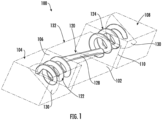
- FIG. 1 illustrates a perspective view of a protection device, such as a fuse 100, in accordance with a non-limiting embodiment of the present disclosure.
- the fuse 100 may include a body 102.
- the body 102 may be ceramic, plastic, or other suitable electrically non-conducting material.
- the body 102 is hollow.
- a first endcap 104 may be coupled to, or fit over, a first end 106 of the body 102, and a second endcap 108 may be coupled to, or fit over, a second end 110 of the body 102.
- the fuse 100 further includes a fusible element 120, such as wire.
- the fusible element 120 may be disposed within the body 102.
- the fusible element 120 includes a first coil 122 coupled to the first endcap 104 and a second coil 124 coupled to the second endcap 108. Extending diagonally between the first and second coils 122, 124 is a central wire 128. In some embodiments, the central wire 128 may be substantially straight.
- solder 130 may be disposed within each of the first and second endcaps 104 and 108. More specifically, the solder 130 may be disposed between the first end 106 of the body 102 and the first endcap 104, and between the second end 110 of the body 102 and the second endcap 108. As shown, the solder 130 may be electrically and mechanically connected to the first coil 122 and the second coil 124.
- the body 102 includes a central portion 132 extending between the first and second ends 106, 110.
- the central portion 132 has an outer cross-sectional profile of a first size.
- the first and second ends 106, 110 of the body 102 have an outer cross-sectional profile of a second size, where the second size is less than the first size.
- the first size and the second size may be the same in other embodiments.
- the fusible element 120 extends through a cavity that is defined between an outer periphery of the first end 106 and an inside surface of the first endcap 104.
- the fusible element 120 extends along a substantially diagonal path through a center of the cavity and terminates at the second end 110, which is at least partially covered by the second endcap 108.
- the cavity enables the solder 130 to completely surround at least a portion of the fusible element 120 disposed therein.
- the fusible element 120 does not come into direct contact with the interior surfaces of the body 102 defining the cavity.
- FIG. 2 illustrates a perspective view of a protection device, such as a fuse 200, in accordance with a non-limiting embodiment of the present disclosure.
- the fuse 200 may share many of the same features to the fuse 100 described above. As such, some aspects of the fuse 200 may not be described in detail for the sake brevity.
- the fuse 200 may include a body 202.
- the body 202 may be ceramic, plastic, or other suitable electrically non-conducting material.
- the body 202 is hollow.
- a first endcap 204 may be coupled to, or fit over, a first end 206 of the body 202, and a second endcap 208 may be coupled to, or fit over, a second end 210 of the body 202.
- the fuse 200 further includes a fusible element 220, such as wire.
- the fusible element 220 may be disposed within the body 202.
- the fusible element 220 includes a first coil 222 coupled to the first endcap 204 and a second coil 224 coupled to the second endcap 208. Extending diagonally between the first and second coils 222, 224 is a central wire 228. In some embodiments, the central wire 228 may be substantially straight.
- the fuse 200 may be solderless.
- the first coil 222 is coupled to, or wound about, a first tube 234 of the first endcap 204.
- the second coil 224 is coupled to a second tube 236 of the second endcap 208.
- the first tube 234 and the second tube 236 may be an type of post or support extending from respective endcaps 204, 208 towards the body 202.
- the first and second tubes 234, 236 may each be metallic a tubes.
- the fusible element 220 extends through a cavity that is defined between an outer periphery of the first end 206 and an inside surface of the first endcap 204.
- the fusible element 220 extends along a substantially diagonal path through a center of the cavity and terminates at the second end 210, which is at least partially covered by the second endcap 208.
- the fusible element 220 does not come into direct contact with the interior surfaces of the body 202 defining the cavity.
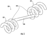
- the fusible element 320 may be the same or similar to the fusible element 120 and fusible element 220 described above.
- the fusible element 320 may include a first coil 322 opposite a second coil 324.
- a central wire 328 extends diagonally between the first and second coils 322, 324.
- each of the first and second coils 322, 324 may include a plurality of loops winding generally about a central axis, A-A.
- Each of the first and second coils 322, 324 may have any number of loops depending on the application.
- the central wire 328 is non-parallel with the central axis A-A.
- the first and second coils 322, 324 may create a bottle configuration of magnetic lines 340, which can confine an arc 344 around an approximate midpoint of the central wire 328. With the arc 344 confined at the center between the first and second coils 322, 324, damage to the first coil 322, the second coil 324, the body and the endcaps (not shown) is mitigated.
- the first and second coils 322, 324 are wound in a same direction (e.g., clockwise).
- the first and second coils 322, 324 of the fusible element may be wound in opposite directions.
- the magnetic field lines 340 create magnetic repulsion between the first and second coils 322, 324.
- the repulsion aids with separation of the fusible element 320 following a break.
- the fusible element 320 may include an arc quencher material 350 (e.g., silicone) within and/or around the first and second coils 322 and 324, as shown in FIG. 5 .
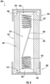
- FIG. 6 illustrates a cross-sectional view of the inventive fuse 400.
- the body 402 includes a central portion 432 disposed between a first end 406 and a second end 410. As shown, the central portion 432 may have an outer square cross-sectional profile. However, embodiment of the present disclosure are not limited to any particular shape or cross-sectional profile. For example, in some embodiments, the body 402 may have a generally circular profile in cross-section, e.g., as viewed from the first end 406 and the second end 410.
- the central portion 432 includes a central cavity 455 extending between the first end 406 and the second end 410, and a plurality of exterior surfaces defining the outer cross-sectional profile of a first size.
- the body 402 includes four (4) generally flat exterior surfaces.
- the body 402 may be ceramic, plastic, or other suitable electrically non-conducting material.
- a first endcap 404 may fit over the first end 406 of the body 402, and a second 408 1164 may fit over the second end 410 of the body 402.
- solder 430 is disposed within the central cavity 455 and along a first end surface 456 of the first end 406 of the body 402.
- the first coil 422 has a free end (not shown), which is surrounded by the solder 430 proximate the first end 406 of the body 402.
- the solder 430 extends along a second end surface 458 of the second end 410 of the body 402.
- the second coil 424 has a free end, which is surrounded by the solder 430 proximate the second end 410 of the body 402.
- an arc quenching material e.g., silicone
- the central wire 428 of the fusible element 420 is disposed within the central cavity 455 of the body 402.
- the central wire 428 is a diagonal wire extending between the first and second coils 422, 424. More specifically, the central wire 428 includes a first end 460 integrally coupled with a first end 462 of the first coil 422. A second end 464 of the central wire 428 is integrally coupled with a second end 466 of the second coil 424.
- the first and second coils 422, 424 are positioned within the first endcap 404 and the second endcap 408, respectively.
- the first coil 422 also extends within the central cavity 455 proximate the first end 406 of the body 402, and the second coil 424 extends within the central cavity 455 proximate the second end 410 of the body 402.
- a magnetic field is created, which helps confine arc plasma, enhancing the breaking capacity of the fuse 400.
- the loop area of the first and/or second coils could also hold a silicone material for additional arc quenching capability. It will be appreciated that a number coils, thickness of material, and diameter of the loops, among other parameters, may vary, and may be dependent in part on the geometries of the body 402 and the central cavity 455, as well as the rating of the fuse 400.
- the free end of the first and/or second coils 422, 424 may extend along respective first and second end surfaces 456, 458.
- the fusible element 420 may also extend along the partially along the one or more of the plurality of exterior surfaces of the body 402.
- a fusible element having coils disposed at opposite ends of a diagonal wire.
- the first and second coils may be wound in a same direction, thus creating a magnetic bottle configuration (also called magnetic mirror), which can advantageously confine an arc at the center of the diagonal wire. With the arc confined at the center, damage of the fuse terminals/caps and body will be mitigated.
- the first and second coils may be wound in opposite directions. As a result, the first and second coils will advantageously repel one another once a strong magnetic field is created, e.g., in the event of an overcurrent condition.
- each of the expressions “at least one of A, B and C”, “at least one of A, B, or C”, “one or more of A, B, and C", “one or more of A, B, or C" and "A, B, and/or C” means A alone, B alone, C alone, A and B together, A and C together, B and C together, or A, B and C together.
- All directional references e.g., proximal, distal, upper, lower, upward, downward, left, right, lateral, longitudinal, front, back, top, bottom, above, below, vertical, horizontal, radial, axial, clockwise, and counterclockwise
- Connection references e.g., attached, coupled, connected, and joined
- connection references are to be construed broadly and may include intermediate members between a collection of elements and relative movement between elements unless otherwise indicated. As such, connection references do not necessarily infer that two elements are directly connected and in fixed relation to each other.
- identification references e.g., primary, secondary, first, second, third, fourth, etc. are not intended to connote importance or priority but are used to distinguish one feature from another.
- the drawings are for purposes of illustration only and the dimensions, positions, order and relative sizes reflected in the drawings attached hereto may vary.
- the terms “substantial” or “substantially,” as well as the terms “approximate” or “approximately,” can be used interchangeably in some embodiments, and can be described using any relative measures acceptable by one of ordinary skill in the art. For example, these terms can serve as a comparison to a reference parameter, to indicate a deviation capable of providing the intended function. Although non-limiting, the deviation from the reference parameter can be, for example, in an amount of less than 1%, less than 3%, less than 5%, less than 10%, less than 15%, less than 20%, and so on.
Landscapes
- Fuses (AREA)
Claims (9)
- Sicherung (100), umfassend:einen Körper (102), einschließlich eines Mittelabschnitts, der sich zwischen einem ersten Ende (106) und einem zweiten Ende (110) erstreckt;eine erste Endkappe (104), die das erste Ende (106) umgibt, und eine zweite Endkappe (108), die das zweite Ende (110) umgibt; undeinen Schmelzleiter (120), der innerhalb eines mittigen Hohlraums des Körpers (102) angeordnet ist, der Schmelzleiter (120) umfassend:eine erste Spule (122), die innerhalb der ersten Endkappe (108) angeordnet ist, und eine zweite Spule (124), die innerhalb der zweiten Endkappe (108) angeordnet ist; undeinen mittigen Draht (128), der sich zwischen der ersten und der zweiten Spule (122, 124) diagonal erstreckt;wobei die erste Spule (122) ein freies Ende, das mit einer ersten Endoberfläche innerhalb des ersten Endes (106) des Körpers (102) mit Lot (130) verbunden ist, aufweist, und wobei die zweite Spule (124) ein freies Ende, das mit einer zweiten Endoberfläche innerhalb des zweiten Endes (110) des Körpers (102) mit Lot (130) verbunden ist, aufweist.
- Sicherung (100) nach Anspruch 1, wobei das Lot (130) innerhalb der ersten Endkappe (104) und der zweiten Endkappe (108) angeordnet ist.
- Sicherung (100, 200) nach Anspruch 2, wobei das Lot (130) ferner zwischen dem ersten Ende (106) und der ersten Endkappe (104) und zwischen dem zweiten Ende (110) und der zweiten Endkappe (108) angeordnet ist.
- Sicherung (100, 200) nach Anspruch 1, ferner umfassend ein erstes Rohr (234) der ersten Endkappe (104, 204) und ein zweites Rohr (236) der zweiten Endkappe (108, 208), wobei die erste Spule (122, 222) mit dem ersten Rohr (234) gekoppelt ist, und wobei die zweite Spule (124, 224) mit dem zweiten Rohr (236) gekoppelt ist.
- Sicherung (100, 200) nach Anspruch 4, wobei die erste Spule (122, 222) teilweise um das erste Rohr (234) gewickelt ist, und wobei die zweite Spule (124, 224) teilweise um das zweite Rohr (236) gewickelt ist.
- Sicherung (100) nach einem der vorstehenden Ansprüche, ferner umfassend innerhalb des Körpers (102) ein lichtbogenlöschendes Material.
- Sicherung (100) nach einem der vorstehenden Ansprüche, wobei die erste und die zweite Spule (122, 124) in eine gleiche Richtung gewickelt sind.
- Sicherung (100) nach einem der vorstehenden Ansprüche 1 bis 6, wobei die erste und die zweite Spule (122, 124) in entgegengesetzte Richtungen gewickelt sind.
- Sicherung (100) nach einem der vorstehenden Ansprüche, wobei der mittige Draht (128) des Schmelzleiters (120) im Wesentlichen gerade ist.
Applications Claiming Priority (1)
| Application Number | Priority Date | Filing Date | Title |
|---|---|---|---|
| US16/162,846 US10446354B1 (en) | 2018-10-17 | 2018-10-17 | Coiled fusible element for high reliability fuse |
Publications (3)
| Publication Number | Publication Date |
|---|---|
| EP3640966A2 EP3640966A2 (de) | 2020-04-22 |
| EP3640966A3 EP3640966A3 (de) | 2020-07-01 |
| EP3640966B1 true EP3640966B1 (de) | 2025-01-08 |
Family
ID=68164926
Family Applications (1)
| Application Number | Title | Priority Date | Filing Date |
|---|---|---|---|
| EP19203194.6A Active EP3640966B1 (de) | 2018-10-17 | 2019-10-15 | Gewickeltes schmelzelement für eine hochsicherheitssicherung |
Country Status (3)
| Country | Link |
|---|---|
| US (1) | US10446354B1 (de) |
| EP (1) | EP3640966B1 (de) |
| CN (1) | CN111063590B (de) |
Families Citing this family (1)
| Publication number | Priority date | Publication date | Assignee | Title |
|---|---|---|---|---|
| CN114899060B (zh) * | 2022-05-16 | 2023-06-06 | 保定市博远电气制造有限公司 | 一种用于电路控制的熔断器 |
Family Cites Families (36)
| Publication number | Priority date | Publication date | Assignee | Title |
|---|---|---|---|---|
| US1545550A (en) * | 1923-10-26 | 1925-07-14 | Coates Frank | Electric fuse |
| US1757753A (en) * | 1926-11-09 | 1930-05-06 | Siemens Ag | Cartridge fuse |
| US3002071A (en) * | 1957-11-11 | 1961-09-26 | Oerlikon Engineering Company | Heavy duty fuse |
| DE1896180U (de) * | 1964-02-05 | 1964-07-09 | Witte & Sutor Kondensatoren Un | Schmelzsicherung, insbesondere geraeteschutzsicherung. |
| NL134303C (de) * | 1967-05-24 | |||
| US3368047A (en) * | 1967-06-19 | 1968-02-06 | Westinghouse Electric Corp | Fuse having a sand core |
| US3713065A (en) * | 1970-06-12 | 1973-01-23 | Ferraz & Cie Lucien | Fast-acting electrical fuse |
| US3648210A (en) * | 1971-01-26 | 1972-03-07 | Chase Shawmut Co | High-voltage fuse with self-supporting spring fuse link |
| BE789422A (fr) * | 1971-09-30 | 1973-03-28 | Westinghouse Electric Corp | Fusible de limitation de courant |
| US3713063A (en) * | 1972-03-13 | 1973-01-23 | S & C Electric Co | Method of and means for making a current limiting fuse |
| JPS49118032U (de) * | 1973-02-07 | 1974-10-09 | ||
| US3849754A (en) * | 1973-10-17 | 1974-11-19 | Westinghouse Electric Corp | Current limiting fuse |
| US3983524A (en) * | 1975-10-09 | 1976-09-28 | General Electric Company | Electrical current limiting fuse having fusible element with additional cross-sectional necks at an arcing clip |
| GB2029131B (en) * | 1978-07-18 | 1982-03-24 | Beswick Ltd K | Electrical fuselinks |
| US4460887A (en) * | 1981-03-19 | 1984-07-17 | Littelfuse, Inc. | Electrical fuse |
| NL8300581A (nl) * | 1983-02-16 | 1984-09-17 | Hazemeijer Bv | Samenstel voor een stroombegrenzende hoogspannings-smeltveiligheid. |
| NL8300953A (nl) * | 1983-03-16 | 1984-10-16 | Hazemeijer Bv | Eindkapkonstruktie voor een hoogspanningssmeltveiligheid. |
| US4506249A (en) * | 1983-09-08 | 1985-03-19 | Rte Corporation | Fuse element termination for current-limiting fuse |
| US4517544A (en) * | 1983-10-24 | 1985-05-14 | Mcgraw-Edison Company | Time delay electric fuse |
| US4736180A (en) * | 1987-07-01 | 1988-04-05 | Littelfuse, Inc. | Fuse wire assembly for electrical fuse |
| US4972169A (en) * | 1988-06-09 | 1990-11-20 | Cooper Industries, Inc. | Spiral wound sand fuse |
| US5485136A (en) * | 1992-09-17 | 1996-01-16 | Cooper Industries, Inc. | Load break disconnecting device with solid arc suppression means |
| US5736919A (en) * | 1996-02-13 | 1998-04-07 | Cooper Industries, Inc. | Spiral wound fuse having resiliently deformable silicone core |
| TW345672B (en) * | 1996-08-01 | 1998-11-21 | Bel Fuse Ine | Conductive epoxy fuse and method of making |
| US6552646B1 (en) * | 2000-04-10 | 2003-04-22 | Bel-Fuse, Inc. | Capless fuse |
| JP3820143B2 (ja) * | 2001-02-16 | 2006-09-13 | エス・オー・シー株式会社 | 表面実装型小型ヒューズ |
| DE10339441B3 (de) * | 2003-08-25 | 2005-06-23 | Wickmann-Werke Gmbh | Röhrenschmelzsicherungsbauelement mit Endkappen mit hermetisch abdichtender Kunststoffdichtungskörpereinlage |
| US20070285867A1 (en) * | 2006-06-13 | 2007-12-13 | Cooper Technologies Company | High resistance current limiting fuse, methods, and systems |
| JP5050265B2 (ja) * | 2007-11-09 | 2012-10-17 | 国立大学法人九州工業大学 | 自己回復性限流ヒューズ |
| GB2461024B (en) * | 2008-06-16 | 2012-06-13 | Converteam Technology Ltd | Fuses |
| US8937524B2 (en) * | 2009-03-25 | 2015-01-20 | Littelfuse, Inc. | Solderless surface mount fuse |
| US9117615B2 (en) * | 2010-05-17 | 2015-08-25 | Littlefuse, Inc. | Double wound fusible element and associated fuse |
| JP6479707B2 (ja) * | 2016-04-27 | 2019-03-06 | 太陽誘電株式会社 | 電子部品用ヒューズ、並びに、ヒューズ付き電子部品モジュール |
| CN205621694U (zh) * | 2016-05-04 | 2016-10-05 | 好利来(厦门)电路保护科技有限公司 | 一种保险丝的可熔体结构 |
| US10325744B2 (en) * | 2016-06-01 | 2019-06-18 | Littelfuse, Inc. | Hollow fuse body with notched ends |
| US10276338B2 (en) * | 2016-06-01 | 2019-04-30 | Littelfuse, Inc. | Hollow fuse body with trench |
-
2018
- 2018-10-17 US US16/162,846 patent/US10446354B1/en active Active
-
2019
- 2019-10-11 CN CN201910966827.0A patent/CN111063590B/zh active Active
- 2019-10-15 EP EP19203194.6A patent/EP3640966B1/de active Active
Also Published As
| Publication number | Publication date |
|---|---|
| CN111063590A (zh) | 2020-04-24 |
| EP3640966A2 (de) | 2020-04-22 |
| CN111063590B (zh) | 2024-12-17 |
| EP3640966A3 (de) | 2020-07-01 |
| US10446354B1 (en) | 2019-10-15 |
Similar Documents
| Publication | Publication Date | Title |
|---|---|---|
| US9117615B2 (en) | Double wound fusible element and associated fuse | |
| US6163002A (en) | Vacuum circuit interrupter with contact structure including support pins | |
| US9601297B2 (en) | High voltage compact fuse assembly with magnetic arc deflection | |
| EP3244437A1 (de) | Hochspannungs-gleichstrom-temperatursicherung | |
| US6614340B2 (en) | Full-range high voltage current limiting fuse | |
| US6778061B2 (en) | Fuse | |
| CN212277139U (zh) | 一种按时序可依次熔断的熔体结构 | |
| EP3640966B1 (de) | Gewickeltes schmelzelement für eine hochsicherheitssicherung | |
| US20160189905A1 (en) | Protection Device Employing Current Limiting Fuse and Vacuum Fuse | |
| CN117334542B (zh) | 一种分隔腔体带隔离灭弧的熔断器 | |
| CN110323112B (zh) | 一种能承载电流和电弧的气体放电装置 | |
| US3733572A (en) | Current limiting fuse | |
| US10854415B1 (en) | Fuse | |
| US11251008B2 (en) | High voltage cartridge fuse assembly | |
| US20160189904A1 (en) | Protection Device Comprising a Plurality of Vacuum Fuses | |
| US11948767B1 (en) | Protection device with wall vent for breaking capacity improvement | |
| CN109411309B (zh) | 熔断结构及熔断器 | |
| JP2873169B2 (ja) | 引込用ヒューズ内蔵コネクター | |
| KR20250080620A (ko) | 전력 퓨즈 | |
| CN219350137U (zh) | 一种熔断器 | |
| EP3889989A1 (de) | Verfahren zur herstellung einer sicherung mit silikonelementen | |
| US20160189903A1 (en) | Vacuum Fuse | |
| CN112309800A (zh) | 保险丝 | |
| KR20200121120A (ko) | 퓨즈 및 그 제조 방법 | |
| JPS58178938A (ja) | 電力ヒユ−ズエレメント |
Legal Events
| Date | Code | Title | Description |
|---|---|---|---|
| PUAI | Public reference made under article 153(3) epc to a published international application that has entered the european phase |
Free format text: ORIGINAL CODE: 0009012 |
|
| STAA | Information on the status of an ep patent application or granted ep patent |
Free format text: STATUS: THE APPLICATION HAS BEEN PUBLISHED |
|
| AK | Designated contracting states |
Kind code of ref document: A2 Designated state(s): AL AT BE BG CH CY CZ DE DK EE ES FI FR GB GR HR HU IE IS IT LI LT LU LV MC MK MT NL NO PL PT RO RS SE SI SK SM TR |
|
| AX | Request for extension of the european patent |
Extension state: BA ME |
|
| PUAL | Search report despatched |
Free format text: ORIGINAL CODE: 0009013 |
|
| AK | Designated contracting states |
Kind code of ref document: A3 Designated state(s): AL AT BE BG CH CY CZ DE DK EE ES FI FR GB GR HR HU IE IS IT LI LT LU LV MC MK MT NL NO PL PT RO RS SE SI SK SM TR |
|
| AX | Request for extension of the european patent |
Extension state: BA ME |
|
| RIC1 | Information provided on ipc code assigned before grant |
Ipc: H01H 85/157 20060101ALN20200526BHEP Ipc: H01H 85/08 20060101AFI20200526BHEP Ipc: H01H 85/38 20060101ALN20200526BHEP |
|
| STAA | Information on the status of an ep patent application or granted ep patent |
Free format text: STATUS: REQUEST FOR EXAMINATION WAS MADE |
|
| 17P | Request for examination filed |
Effective date: 20201126 |
|
| RBV | Designated contracting states (corrected) |
Designated state(s): AL AT BE BG CH CY CZ DE DK EE ES FI FR GB GR HR HU IE IS IT LI LT LU LV MC MK MT NL NO PL PT RO RS SE SI SK SM TR |
|
| STAA | Information on the status of an ep patent application or granted ep patent |
Free format text: STATUS: EXAMINATION IS IN PROGRESS |
|
| 17Q | First examination report despatched |
Effective date: 20220711 |
|
| GRAP | Despatch of communication of intention to grant a patent |
Free format text: ORIGINAL CODE: EPIDOSNIGR1 |
|
| STAA | Information on the status of an ep patent application or granted ep patent |
Free format text: STATUS: GRANT OF PATENT IS INTENDED |
|
| INTG | Intention to grant announced |
Effective date: 20240801 |
|
| P01 | Opt-out of the competence of the unified patent court (upc) registered |
Free format text: CASE NUMBER: APP_48100/2024 Effective date: 20240821 |
|
| GRAS | Grant fee paid |
Free format text: ORIGINAL CODE: EPIDOSNIGR3 |
|
| GRAA | (expected) grant |
Free format text: ORIGINAL CODE: 0009210 |
|
| STAA | Information on the status of an ep patent application or granted ep patent |
Free format text: STATUS: THE PATENT HAS BEEN GRANTED |
|
| AK | Designated contracting states |
Kind code of ref document: B1 Designated state(s): AL AT BE BG CH CY CZ DE DK EE ES FI FR GB GR HR HU IE IS IT LI LT LU LV MC MK MT NL NO PL PT RO RS SE SI SK SM TR |
|
| REG | Reference to a national code |
Ref country code: GB Ref legal event code: FG4D |
|
| REG | Reference to a national code |
Ref country code: CH Ref legal event code: EP |
|
| REG | Reference to a national code |
Ref country code: DE Ref legal event code: R096 Ref document number: 602019064541 Country of ref document: DE |
|
| REG | Reference to a national code |
Ref country code: IE Ref legal event code: FG4D |
|
| REG | Reference to a national code |
Ref country code: LT Ref legal event code: MG9D |
|
| REG | Reference to a national code |
Ref country code: NL Ref legal event code: MP Effective date: 20250108 |
|
| REG | Reference to a national code |
Ref country code: AT Ref legal event code: MK05 Ref document number: 1758898 Country of ref document: AT Kind code of ref document: T Effective date: 20250108 |
|
| PG25 | Lapsed in a contracting state [announced via postgrant information from national office to epo] |
Ref country code: NL Free format text: LAPSE BECAUSE OF FAILURE TO SUBMIT A TRANSLATION OF THE DESCRIPTION OR TO PAY THE FEE WITHIN THE PRESCRIBED TIME-LIMIT Effective date: 20250108 |
|
| PG25 | Lapsed in a contracting state [announced via postgrant information from national office to epo] |
Ref country code: RS Free format text: LAPSE BECAUSE OF FAILURE TO SUBMIT A TRANSLATION OF THE DESCRIPTION OR TO PAY THE FEE WITHIN THE PRESCRIBED TIME-LIMIT Effective date: 20250408 |
|
| PG25 | Lapsed in a contracting state [announced via postgrant information from national office to epo] |
Ref country code: FI Free format text: LAPSE BECAUSE OF FAILURE TO SUBMIT A TRANSLATION OF THE DESCRIPTION OR TO PAY THE FEE WITHIN THE PRESCRIBED TIME-LIMIT Effective date: 20250108 |
|
| PG25 | Lapsed in a contracting state [announced via postgrant information from national office to epo] |
Ref country code: PL Free format text: LAPSE BECAUSE OF FAILURE TO SUBMIT A TRANSLATION OF THE DESCRIPTION OR TO PAY THE FEE WITHIN THE PRESCRIBED TIME-LIMIT Effective date: 20250108 |
|
| PG25 | Lapsed in a contracting state [announced via postgrant information from national office to epo] |
Ref country code: ES Free format text: LAPSE BECAUSE OF FAILURE TO SUBMIT A TRANSLATION OF THE DESCRIPTION OR TO PAY THE FEE WITHIN THE PRESCRIBED TIME-LIMIT Effective date: 20250108 |
|
| PG25 | Lapsed in a contracting state [announced via postgrant information from national office to epo] |
Ref country code: NO Free format text: LAPSE BECAUSE OF FAILURE TO SUBMIT A TRANSLATION OF THE DESCRIPTION OR TO PAY THE FEE WITHIN THE PRESCRIBED TIME-LIMIT Effective date: 20250408 Ref country code: IS Free format text: LAPSE BECAUSE OF FAILURE TO SUBMIT A TRANSLATION OF THE DESCRIPTION OR TO PAY THE FEE WITHIN THE PRESCRIBED TIME-LIMIT Effective date: 20250508 |
|
| PG25 | Lapsed in a contracting state [announced via postgrant information from national office to epo] |
Ref country code: HR Free format text: LAPSE BECAUSE OF FAILURE TO SUBMIT A TRANSLATION OF THE DESCRIPTION OR TO PAY THE FEE WITHIN THE PRESCRIBED TIME-LIMIT Effective date: 20250108 |
|
| PG25 | Lapsed in a contracting state [announced via postgrant information from national office to epo] |
Ref country code: LV Free format text: LAPSE BECAUSE OF FAILURE TO SUBMIT A TRANSLATION OF THE DESCRIPTION OR TO PAY THE FEE WITHIN THE PRESCRIBED TIME-LIMIT Effective date: 20250108 Ref country code: PT Free format text: LAPSE BECAUSE OF FAILURE TO SUBMIT A TRANSLATION OF THE DESCRIPTION OR TO PAY THE FEE WITHIN THE PRESCRIBED TIME-LIMIT Effective date: 20250508 |
|
| PG25 | Lapsed in a contracting state [announced via postgrant information from national office to epo] |
Ref country code: BG Free format text: LAPSE BECAUSE OF FAILURE TO SUBMIT A TRANSLATION OF THE DESCRIPTION OR TO PAY THE FEE WITHIN THE PRESCRIBED TIME-LIMIT Effective date: 20250108 Ref country code: GR Free format text: LAPSE BECAUSE OF FAILURE TO SUBMIT A TRANSLATION OF THE DESCRIPTION OR TO PAY THE FEE WITHIN THE PRESCRIBED TIME-LIMIT Effective date: 20250409 |
|
| PG25 | Lapsed in a contracting state [announced via postgrant information from national office to epo] |
Ref country code: AT Free format text: LAPSE BECAUSE OF FAILURE TO SUBMIT A TRANSLATION OF THE DESCRIPTION OR TO PAY THE FEE WITHIN THE PRESCRIBED TIME-LIMIT Effective date: 20250108 |
|
| PG25 | Lapsed in a contracting state [announced via postgrant information from national office to epo] |
Ref country code: SE Free format text: LAPSE BECAUSE OF FAILURE TO SUBMIT A TRANSLATION OF THE DESCRIPTION OR TO PAY THE FEE WITHIN THE PRESCRIBED TIME-LIMIT Effective date: 20250108 |
|
| PG25 | Lapsed in a contracting state [announced via postgrant information from national office to epo] |
Ref country code: SM Free format text: LAPSE BECAUSE OF FAILURE TO SUBMIT A TRANSLATION OF THE DESCRIPTION OR TO PAY THE FEE WITHIN THE PRESCRIBED TIME-LIMIT Effective date: 20250108 |
|
| REG | Reference to a national code |
Ref country code: DE Ref legal event code: R097 Ref document number: 602019064541 Country of ref document: DE |
|
| PG25 | Lapsed in a contracting state [announced via postgrant information from national office to epo] |
Ref country code: DK Free format text: LAPSE BECAUSE OF FAILURE TO SUBMIT A TRANSLATION OF THE DESCRIPTION OR TO PAY THE FEE WITHIN THE PRESCRIBED TIME-LIMIT Effective date: 20250108 |
|
| PG25 | Lapsed in a contracting state [announced via postgrant information from national office to epo] |
Ref country code: EE Free format text: LAPSE BECAUSE OF FAILURE TO SUBMIT A TRANSLATION OF THE DESCRIPTION OR TO PAY THE FEE WITHIN THE PRESCRIBED TIME-LIMIT Effective date: 20250108 Ref country code: CZ Free format text: LAPSE BECAUSE OF FAILURE TO SUBMIT A TRANSLATION OF THE DESCRIPTION OR TO PAY THE FEE WITHIN THE PRESCRIBED TIME-LIMIT Effective date: 20250108 |
|
| PG25 | Lapsed in a contracting state [announced via postgrant information from national office to epo] |
Ref country code: RO Free format text: LAPSE BECAUSE OF FAILURE TO SUBMIT A TRANSLATION OF THE DESCRIPTION OR TO PAY THE FEE WITHIN THE PRESCRIBED TIME-LIMIT Effective date: 20250108 |
|
| PG25 | Lapsed in a contracting state [announced via postgrant information from national office to epo] |
Ref country code: SK Free format text: LAPSE BECAUSE OF FAILURE TO SUBMIT A TRANSLATION OF THE DESCRIPTION OR TO PAY THE FEE WITHIN THE PRESCRIBED TIME-LIMIT Effective date: 20250108 |
|
| PLBE | No opposition filed within time limit |
Free format text: ORIGINAL CODE: 0009261 |
|
| STAA | Information on the status of an ep patent application or granted ep patent |
Free format text: STATUS: NO OPPOSITION FILED WITHIN TIME LIMIT |
|
| 26N | No opposition filed |
Effective date: 20251009 |
|
| PGFP | Annual fee paid to national office [announced via postgrant information from national office to epo] |
Ref country code: DE Payment date: 20250902 Year of fee payment: 7 |
|
| PG25 | Lapsed in a contracting state [announced via postgrant information from national office to epo] |
Ref country code: IT Free format text: LAPSE BECAUSE OF FAILURE TO SUBMIT A TRANSLATION OF THE DESCRIPTION OR TO PAY THE FEE WITHIN THE PRESCRIBED TIME-LIMIT Effective date: 20250108 |