EP3640177A1 - Alimentation électrique pour charges ca lors d'une panne d'alimentation dans un système d'ascenseur - Google Patents
Alimentation électrique pour charges ca lors d'une panne d'alimentation dans un système d'ascenseur Download PDFInfo
- Publication number
- EP3640177A1 EP3640177A1 EP18201465.4A EP18201465A EP3640177A1 EP 3640177 A1 EP3640177 A1 EP 3640177A1 EP 18201465 A EP18201465 A EP 18201465A EP 3640177 A1 EP3640177 A1 EP 3640177A1
- Authority
- EP
- European Patent Office
- Prior art keywords
- power
- power source
- management system
- bus
- common
- Prior art date
- Legal status (The legal status is an assumption and is not a legal conclusion. Google has not performed a legal analysis and makes no representation as to the accuracy of the status listed.)
- Withdrawn
Links
Images
Classifications
-
- H—ELECTRICITY
- H02—GENERATION; CONVERSION OR DISTRIBUTION OF ELECTRIC POWER
- H02J—CIRCUIT ARRANGEMENTS OR SYSTEMS FOR SUPPLYING OR DISTRIBUTING ELECTRIC POWER; SYSTEMS FOR STORING ELECTRIC ENERGY
- H02J3/00—Circuit arrangements for ac mains or ac distribution networks
-
- B—PERFORMING OPERATIONS; TRANSPORTING
- B66—HOISTING; LIFTING; HAULING
- B66B—ELEVATORS; ESCALATORS OR MOVING WALKWAYS
- B66B1/00—Control systems of elevators in general
- B66B1/24—Control systems with regulation, i.e. with retroactive action, for influencing travelling speed, acceleration, or deceleration
- B66B1/28—Control systems with regulation, i.e. with retroactive action, for influencing travelling speed, acceleration, or deceleration electrical
- B66B1/30—Control systems with regulation, i.e. with retroactive action, for influencing travelling speed, acceleration, or deceleration electrical effective on driving gear, e.g. acting on power electronics, on inverter or rectifier controlled motor
- B66B1/302—Control systems with regulation, i.e. with retroactive action, for influencing travelling speed, acceleration, or deceleration electrical effective on driving gear, e.g. acting on power electronics, on inverter or rectifier controlled motor for energy saving
-
- B—PERFORMING OPERATIONS; TRANSPORTING
- B66—HOISTING; LIFTING; HAULING
- B66B—ELEVATORS; ESCALATORS OR MOVING WALKWAYS
- B66B1/00—Control systems of elevators in general
- B66B1/24—Control systems with regulation, i.e. with retroactive action, for influencing travelling speed, acceleration, or deceleration
- B66B1/28—Control systems with regulation, i.e. with retroactive action, for influencing travelling speed, acceleration, or deceleration electrical
- B66B1/30—Control systems with regulation, i.e. with retroactive action, for influencing travelling speed, acceleration, or deceleration electrical effective on driving gear, e.g. acting on power electronics, on inverter or rectifier controlled motor
- B66B1/306—Control systems with regulation, i.e. with retroactive action, for influencing travelling speed, acceleration, or deceleration electrical effective on driving gear, e.g. acting on power electronics, on inverter or rectifier controlled motor with DC powered elevator drive
-
- B—PERFORMING OPERATIONS; TRANSPORTING
- B66—HOISTING; LIFTING; HAULING
- B66B—ELEVATORS; ESCALATORS OR MOVING WALKWAYS
- B66B1/00—Control systems of elevators in general
- B66B1/24—Control systems with regulation, i.e. with retroactive action, for influencing travelling speed, acceleration, or deceleration
- B66B1/28—Control systems with regulation, i.e. with retroactive action, for influencing travelling speed, acceleration, or deceleration electrical
- B66B1/30—Control systems with regulation, i.e. with retroactive action, for influencing travelling speed, acceleration, or deceleration electrical effective on driving gear, e.g. acting on power electronics, on inverter or rectifier controlled motor
- B66B1/308—Control systems with regulation, i.e. with retroactive action, for influencing travelling speed, acceleration, or deceleration electrical effective on driving gear, e.g. acting on power electronics, on inverter or rectifier controlled motor with AC powered elevator drive
-
- H—ELECTRICITY
- H02—GENERATION; CONVERSION OR DISTRIBUTION OF ELECTRIC POWER
- H02J—CIRCUIT ARRANGEMENTS OR SYSTEMS FOR SUPPLYING OR DISTRIBUTING ELECTRIC POWER; SYSTEMS FOR STORING ELECTRIC ENERGY
- H02J3/00—Circuit arrangements for ac mains or ac distribution networks
- H02J3/02—Circuit arrangements for ac mains or ac distribution networks using a single network for simultaneous distribution of power at different frequencies; using a single network for simultaneous distribution of ac power and of dc power
-
- H—ELECTRICITY
- H02—GENERATION; CONVERSION OR DISTRIBUTION OF ELECTRIC POWER
- H02J—CIRCUIT ARRANGEMENTS OR SYSTEMS FOR SUPPLYING OR DISTRIBUTING ELECTRIC POWER; SYSTEMS FOR STORING ELECTRIC ENERGY
- H02J3/00—Circuit arrangements for ac mains or ac distribution networks
- H02J3/28—Arrangements for balancing of the load in a network by storage of energy
- H02J3/32—Arrangements for balancing of the load in a network by storage of energy using batteries with converting means
-
- H—ELECTRICITY
- H02—GENERATION; CONVERSION OR DISTRIBUTION OF ELECTRIC POWER
- H02J—CIRCUIT ARRANGEMENTS OR SYSTEMS FOR SUPPLYING OR DISTRIBUTING ELECTRIC POWER; SYSTEMS FOR STORING ELECTRIC ENERGY
- H02J3/00—Circuit arrangements for ac mains or ac distribution networks
- H02J3/38—Arrangements for parallely feeding a single network by two or more generators, converters or transformers
-
- H—ELECTRICITY
- H02—GENERATION; CONVERSION OR DISTRIBUTION OF ELECTRIC POWER
- H02J—CIRCUIT ARRANGEMENTS OR SYSTEMS FOR SUPPLYING OR DISTRIBUTING ELECTRIC POWER; SYSTEMS FOR STORING ELECTRIC ENERGY
- H02J9/00—Circuit arrangements for emergency or stand-by power supply, e.g. for emergency lighting
- H02J9/04—Circuit arrangements for emergency or stand-by power supply, e.g. for emergency lighting in which the distribution system is disconnected from the normal source and connected to a standby source
- H02J9/06—Circuit arrangements for emergency or stand-by power supply, e.g. for emergency lighting in which the distribution system is disconnected from the normal source and connected to a standby source with automatic change-over, e.g. UPS systems
- H02J9/062—Circuit arrangements for emergency or stand-by power supply, e.g. for emergency lighting in which the distribution system is disconnected from the normal source and connected to a standby source with automatic change-over, e.g. UPS systems for AC powered loads
-
- H—ELECTRICITY
- H02—GENERATION; CONVERSION OR DISTRIBUTION OF ELECTRIC POWER
- H02P—CONTROL OR REGULATION OF ELECTRIC MOTORS, ELECTRIC GENERATORS OR DYNAMO-ELECTRIC CONVERTERS; CONTROLLING TRANSFORMERS, REACTORS OR CHOKE COILS
- H02P3/00—Arrangements for stopping or slowing electric motors, generators, or dynamo-electric converters
- H02P3/06—Arrangements for stopping or slowing electric motors, generators, or dynamo-electric converters for stopping or slowing an individual dynamo-electric motor or dynamo-electric converter
- H02P3/18—Arrangements for stopping or slowing electric motors, generators, or dynamo-electric converters for stopping or slowing an individual dynamo-electric motor or dynamo-electric converter for stopping or slowing an ac motor
- H02P3/22—Arrangements for stopping or slowing electric motors, generators, or dynamo-electric converters for stopping or slowing an individual dynamo-electric motor or dynamo-electric converter for stopping or slowing an ac motor by short-circuit or resistive braking
-
- B—PERFORMING OPERATIONS; TRANSPORTING
- B66—HOISTING; LIFTING; HAULING
- B66B—ELEVATORS; ESCALATORS OR MOVING WALKWAYS
- B66B5/00—Applications of checking, fault-correcting, or safety devices in elevators
- B66B5/02—Applications of checking, fault-correcting, or safety devices in elevators responsive to abnormal operating conditions
Definitions
- the invention relates to power management in an elevator system, in particular, to a method and system for leveraging an elevator system to form a microgrid or a local grid.
- an elevator car makes vertical movements to transport passengers between different floors in a building.
- An electric motor controlled by a power management system is used to drive the elevator car. Stable supply of electric power to the electric motor is important.
- power management systems have been developed to employ various types of power sources.
- Exemplary embodiments of the invention include a power management system for an elevator system, comprising a power converter having input terminals coupled to an AC power source supplying AC power to the power management system and output terminals coupled to a common DC bus, the power converter configured to convert the AC power from the AC power source into DC power on the common DC bus and vice versa; an AC load coupled to the input terminals of the power converter; a second power source for supplying DC power to the common DC bus; a power inverter configured to invert the DC power on the common DC bus into AC output power for driving an electric motor of the elevator system; and a controller configured to detect a failure of the AC power source and, upon detection the failure of the AC power source, to control the power converter to invert the DC power on the common DC bus into AC power to be supplied to the AC load via the input terminals of the power converter.
- Exemplary embodiments of the invention include an elevator system equipped with a power management system according to the embodiments of the present invention.
- Exemplary embodiments of the invention include a method of power management in an elevator system, the method comprising supplying, by an AC power source, AC power to a power converter of a power management system, the power converter configured to convert the AC power into DC power on a common DC bus of the power management system and vice versa; supplying, by the AC power source, AC power to an AC load which is coupled between the AC power source and the power converter; detecting a failure of the AC power source; and upon detection of the failure of the AC power source, controlling the power converter to convert the DC power on the common DC bus to AC output power to be supplied to the AC load.
- Exemplary embodiments of the invention allow for the integration of power sources for an elevator system and for other electrical systems of a building to which the elevator system belongs.
- electrical power from a second power source of an elevator system or electrical power regenerated by an electrical motor of the elevator system can be utilized for driving electrical loads of the building when there is a failure of an AC power source.
- additional hardware and wiring are unnecessary for the electrical loads of the building and thus cost reduction can be achieved.
- a power converter of the elevator system can be redirected to AC loads during a failure of the AC power source and thereby allowing leveraging the power converter to form a microgrid or a local grid.
- an elevator system can be utilized as an uninterruptible power supply or a microgrid for the electrical loads of the building.
- the AC load may comprise an electrical load of the elevator system like elevator door operators, elevator lightings or an additional AC-fed power conversion stage that supplies several loads including back-up supplies used for rescue operation, etc.
- the AC load may further comprise an electrical load of a building to which the elevator system belongs like a building communication system or a building lighting system etc. Without a failure of an AC power source, those elevator door operators, elevator lightings, the building communication system or building lightings can be powered by the AC power source, while, when there is a failure of the AC power source, they can be powered by the elevator system.
- regenerated power by the electric motor may be supplied to the common DC bus via the power inverter, so that the regenerated power can be used for driving the AC load.
- the power management system further comprises a dynamic braking resistor (DBR) coupled to the common DC bus. When current flows through the DBR in regenerative mode, excess energy can be dissipated through the DBR as necessary.
- DBR dynamic braking resistor
- a plurality of dynamic braking resistors may be connected serially or in parallel.
- the power management system may further comprise a supercapacitor stack coupled to the common DC bus, so that excessive power in the common DC bus can be stored in the supercapacitor stack.
- the supercapacitor stack may comprise a single supercapacitor or a plurality of supercapacitors connected serially or in parallel.
- the second power source may be a DC battery.
- the power management system may comprise an alternative power source which is coupled to the common DC bus and configured to provide AC or DC power.
- the alternative power source may comprise a solar panel, a fuel cell or a wind turbine etc.
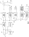
- Fig. 1 is a block diagram of a power management system 1 to be used in an elevator system 2 according to an exemplary embodiment of the invention.
- the power management system 1 shown in Fig. 1 comprises an AC power source 11, a power converter 12, a power inverter 14, an AC load 22, a contactor 23, a controller 24, a DC power source 26, a first DC/DC converter 28, a dynamic braking resistor (DBR, 32), a DBR chopper 30, a second DC/DC converter 36, an alternative power source 34, and a common DC bus 38.
- the power management system 1 may further comprise a supercapacitor stack 40 which is coupled to the common DC bus 38 via a third DC/DC converter 42.
- the elevator system 2 shown in Fig. 1 comprises an electric motor 16, a counterweight 18, a rope 19, and an elevator car 20.
- the electric motor 16 is provided with AC power from the power inverter 14 to drive the elevator car 20 and the counterweight 18 which are connected via the rope 19.
- the AC power supplied to the electric motor 16 may be a single-phase or three-phase AC power provided by the power inverter 14, e.g. by pulse width modulation (PWM) from the DC power in the common DC bus 38.
- PWM pulse width modulation
- the electric motor 16 is capable of operating in a motoring mode or in a regenerative mode.
- the power management system 1 is configured to drive the electric motor 16 based on the single-phase AC power supplied by the AC power source 11.
- each of the DC power source 26, the supercapacitor stack 40, and the alternative power source 34 can also be a power source providing the electric motor 16 with the driving power. Namely, the electric motor 16 can be driven by electric power supplied by a combination of the AC power source 11, the DC power source, and/or the supercapacitor stack 40.
- the DC power source 26 may comprise at least one secondary or rechargeable DC battery.
- the alternative power source 34 may comprise a solar panel, a fuel cell, a wind turbine, or other power generating devices.
- regenerated electric power may be delivered to at least one of the AC power source 11, the DC power source 26 or the supercapacitor stack 40.
- the DC power source 26, the alternative power source 34, and the supercapacitor stack 40 may be coupled to the common DC bus 38 via the first DC/DC converter 28, the second DC/DC converter 36, and the third DC/DC converter 42, respectively.
- the first to third DC/DC converters 28, 36, 42 are optional and may provide for conversion of different voltage levels between each power source 26, 34, 40 and the common DC bus 38. In this way, the DC power source 26 and the alternative power source 34 can supply DC power to the common DC bus 38 as necessary.
- the power inverter 14 may be a three-phase power inverter that is configured to invert the DC power from the common DC bus 38 to three-phase AC power to be delivered to the electric motor 16 to impart motion to the elevator car 20 in a motoring mode.
- this power conversion from DC power to three-phase AC power may be done by operating switches connected in three bridge circuits in the power inverter 14, e.g. such as to apply a pulse width modulation (PWM) power conversion scheme.
- PWM pulse width modulation
- the power inverter 14 can operate in a bidirectional way, so that in the regenerative mode AC power regenerated by the electric motor 16 is converted by the power inverter 14 to DC power to be delivered to the common DC bus 38.
- the power inverter 14 comprises a plurality of power switches to generate drive for the electric motor 16.
- the power switches may be insulated gate bipolar transistors (IGBTs) or metal-oxide-semiconductor field-effect transistors (MOSFETs) transistors, but other types of power switches may be used as well.
- Each power switch normally includes a flybackdiode across its drain-source terminals.
- the flyback diode can be called a freewheeling diode or an antiparallel diode.
- the power switches are arranged in phase legs, each phase leg connected between the positive and negative poles of the common DC bus 38.
- An AC terminal is provided at a junction (e.g., source-drain junction) of the power switches in each phase leg.
- the AC terminal provides the output of the respective phase leg of the power inverter 14.
- the AC terminals are coupled to respective motor windings of the electric motor 16.
- the electric motor 16 is a three-phase, permanent magnet synchronous motor.
- the power inverter 14 may be a three-phase inverter and the electric motor 16 may be a three-phase motor, but embodiments are not limited to a particular number of phases.
- the controller 24 may employ the PWM to produce gating pulses to periodically switch the power switches in the power inverter 14 to supply three-phase AC power to the electric motor 12.
- the speed and direction of movement of the elevator car 20 may be varied by adjusting the frequency and magnitude of the gating pulses provided with the power switches.
- the power converter 12 may be a three-phase bidirectional power converter which is configured to convert the AC power supplied by the AC power source 11 to DC power.
- the three-phase power converter 12 may have a configuration corresponding to the configuration of the power inverter 14.
- the three-phase power converter 12 may also comprise power switches arranged in phase legs, each phase leg connected between the positive and negative poles of the DC bus 38. Different to the power inverter 14, positive and negative poles of the DC bus 38 are coupled to the output of the phase legs of the three-phase power converter 12.
- a terminal provided at a junction (e.g., source-drain junction) of the power switches in each phase leg provides the input of the respective phase leg of the three-phase power converter 12.
- the three-phase power converter 12 may use power switches to convert DC power or AC power supplied to its input to a DC voltage supplied at its output. Power switches may also be IGBTs or MOSFETs, but other types of power switches may be used. Each power switch normally includes a freewheeling diode across its drain-source terminals. Thus, the three-phase power converter 12 is an actively controlled three-phase power converter 12 which is capable of regenerating power from the DC bus 38 to the input side of the three-phase power converter 12, if desired.
- the AC load 22 is connected between the AC power source 11 and the power converter 12.
- the AC power source 11 may be a single-phase or three-phase electrical power supplied from an electric power grid.
- the AC load 22 is provided with AC power from the AC power source 11.
- the controller 24 is configured to control the power converter 12 depending on the normal mode and the power failure mode.
- the contactor 23 is configured to connect or disconnect the AC power source 11 to or from the power converter 12 upon receiving an instruction from the controller 24.
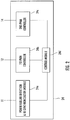
- Fig. 2 is a block diagram depicting a structure of the controller 24 according to an exemplary embodiment of the present invention.
- the controller 24 comprises a power failure detection & re-synchronization module 24a, a first PWM controller 24b, a second PWM controller 24c, and a control module 24d.
- the power failure detection & re-synchronization module 24a is coupled to the AC power source 11 to detect a failure and recovery of the AC power source 11.
- the first PWM controller 24b and the second PWM controller 24c are coupled to the power converter 12 and the power inverter 14, respectively. They are configured to generate PWM pulses to control the power converter 12 and the power inverter 14, respectively.
- the control module 24d is configured to control operations of the power failure detection & re-synchronization module 24a, the first PWM controller 24b, and the second PWM controller 24c.
- the control module 24d directs the first PWM controller 24b to generate PWM pulses for converting AC power from the AC power source 11 to DC power to be delivered to the common DC bus 38.
- the controller 24 instructs the contactor 23 to disconnect the AC power source 11 from the power converter.
- the control module 24d directs the first PWM controller 24b to generate PWM pulses for allowing the power converter 24b to convert the DC power on the common DC bus 38 into AC power to be delivered to the AC load.
- the power converter 12 can be used to form a microgrid or a local grid.
- the AC load 22 may be an electrical load of the elevator system like an elevator door operator, an elevator lighting system or an auxiliary supply etc.
- the AC load 22 may be an electrical load of a building to which the elevator system belongs, such as a building communication system or a building lighting system etc.
- the controller 24 sends an instruction to the contactor 23 to recover a connection between the AC power source 11 and the power converter 12.
- the recovery of the AC power source 11 can be detected by applying a grid synchronization method.
- the control module 24d may enable the second PWM controller 24c to generate PWM pulses for allowing the power inverter 14 to operate according to the motoring mode, the regenerative mode or a braking mode. Particularly, during the motoring mode, the second PWM controller 24c generates PWM pulses to control power switches in the power inverter 14 to apply AC power to the electric motor 16 to impart motion to the elevator car 20. During the regenerative mode, the second PWM controller 24c generates PWM pulses to allow the power switches to convert AC power from the electric motor 16 to DC power to be delivered to at least one of the AC power source 11, the DC power source 26, or the supercapacitor stack 40.
- the regenerative mode may occur when an empty or only lightly loaded elevator car 20 is traveling upwards or when a fully or strongly loaded elevator car 20 is traveling downwards.
- the second PWM controller 24c In the braking mode, the second PWM controller 24c generates PWM pulses for allowing the power switches in the power inverter 14 to control the speed of the elevator car 20.
- the braking mode may ensue upon opening of a safety chain in the elevator, or other event.
- a speed sensor e.g., a rotary encoder mounted at the electric motor 16 or any other rotatable part of the drive machine may provide a speed signal to the controller 24 indicative of the rotational speed of the electric motor 16 or drive machine.
- the controller 24 or the control module 24d may be implemented using a general-purpose microprocessor executing a computer program stored on a storage medium to perform the operations described herein. Alternatively, such controller 24 and control module 24d may be implemented in hardware (e.g., ASIC, FPGA) or in a combination of hardware/software. The controller 24 may also be part of an elevator control system.
- the control module 24 may cause current flow through the dynamic braking resistor 32 in order to dissipate excess energy.
- excess energy is dissipated through the dynamic braking resistor 32.
- a plurality of dynamic braking resistors 32 may be connected serially or in parallel.
- the integration of power sources for an elevator system and for other electrical systems of a building can be achieved.
- electrical power from a second power source of an elevator system electrical power regenerated by an electrical motor of the elevator system, or a combination of both, can be utilized for driving electrical loads of the building when there is a failure of an AC power source.
- additional hardware and wiring are unnecessary for the electrical loads of the building and thus cost reduction can be achieved.
- a power converter of the elevator system can be redirected to AC loads during a failure of the AC power source and thereby allowing leveraging the power converter to form a microgrid or a local grid.
- an elevator system can be utilized as an uninterruptible power supply or a microgrid former for the electrical loads of the building.
Priority Applications (3)
| Application Number | Priority Date | Filing Date | Title |
|---|---|---|---|
| EP18201465.4A EP3640177A1 (fr) | 2018-10-19 | 2018-10-19 | Alimentation électrique pour charges ca lors d'une panne d'alimentation dans un système d'ascenseur |
| CN201910992846.0A CN111082415A (zh) | 2018-10-19 | 2019-10-18 | 电梯系统中的功率源失效期间对ac负载的功率供应 |
| US16/657,603 US20200122961A1 (en) | 2018-10-19 | 2019-10-18 | Power supply to ac loads during power source failure in elevator system |
Applications Claiming Priority (1)
| Application Number | Priority Date | Filing Date | Title |
|---|---|---|---|
| EP18201465.4A EP3640177A1 (fr) | 2018-10-19 | 2018-10-19 | Alimentation électrique pour charges ca lors d'une panne d'alimentation dans un système d'ascenseur |
Publications (1)
| Publication Number | Publication Date |
|---|---|
| EP3640177A1 true EP3640177A1 (fr) | 2020-04-22 |
Family
ID=63965110
Family Applications (1)
| Application Number | Title | Priority Date | Filing Date |
|---|---|---|---|
| EP18201465.4A Withdrawn EP3640177A1 (fr) | 2018-10-19 | 2018-10-19 | Alimentation électrique pour charges ca lors d'une panne d'alimentation dans un système d'ascenseur |
Country Status (3)
| Country | Link |
|---|---|
| US (1) | US20200122961A1 (fr) |
| EP (1) | EP3640177A1 (fr) |
| CN (1) | CN111082415A (fr) |
Cited By (2)
| Publication number | Priority date | Publication date | Assignee | Title |
|---|---|---|---|---|
| US20200122960A1 (en) * | 2018-10-19 | 2020-04-23 | Otis Elevator Company | Power management in an elevator system |
| US20200122961A1 (en) * | 2018-10-19 | 2020-04-23 | Otis Elevator Company | Power supply to ac loads during power source failure in elevator system |
Families Citing this family (3)
| Publication number | Priority date | Publication date | Assignee | Title |
|---|---|---|---|---|
| CN107848734B (zh) * | 2015-08-07 | 2021-06-22 | 奥的斯电梯公司 | 操作包括永磁体(pm)同步电机驱动系统的电梯系统的救援控制和方法 |
| EP3331794A1 (fr) | 2015-08-07 | 2018-06-13 | Otis Elevator Company | Système d'ascenseur comprenant un système d'entraînement par moteur synchrone à aimants permanents (ap) |
| CN114257085A (zh) * | 2021-11-30 | 2022-03-29 | 阳光电源股份有限公司 | 一种功率变换电路及其控制方法和供电系统 |
Citations (2)
| Publication number | Priority date | Publication date | Assignee | Title |
|---|---|---|---|---|
| WO2010042118A1 (fr) * | 2008-10-09 | 2010-04-15 | Otis Elevator Company | Bâtiment à multiples sources de génération d’énergie activées par un système d’ascenseur |
| US20120261217A1 (en) * | 2007-02-13 | 2012-10-18 | Otis Elevator Company | Regenerative drive with backup power supply |
Family Cites Families (17)
| Publication number | Priority date | Publication date | Assignee | Title |
|---|---|---|---|---|
| JP2001240323A (ja) * | 2000-02-28 | 2001-09-04 | Mitsubishi Electric Corp | エレベーターの制御装置 |
| JP4249364B2 (ja) * | 2000-02-28 | 2009-04-02 | 三菱電機株式会社 | エレベータの制御装置 |
| JP4283963B2 (ja) * | 2000-02-28 | 2009-06-24 | 三菱電機株式会社 | エレベータの制御装置 |
| WO2003033390A1 (fr) * | 2001-10-17 | 2003-04-24 | Mitsubishi Denki Kabushiki Kaisha | Organe de commande d'ascenseur |
| RU2490201C2 (ru) * | 2008-08-15 | 2013-08-20 | Отис Элевэйтор Компани | Система питания лифта и здания с управлением вторичным источником питания |
| US9685900B2 (en) * | 2010-11-19 | 2017-06-20 | General Electric Company | Low-inductance, high-efficiency induction machine and method of making same |
| WO2012164597A1 (fr) * | 2011-05-27 | 2012-12-06 | 三菱電機株式会社 | Dispositif de commande pour ascenseur |
| CN103608278B (zh) * | 2011-06-13 | 2015-05-27 | 三菱电机株式会社 | 电梯控制装置 |
| JP5741686B2 (ja) * | 2011-06-13 | 2015-07-01 | 三菱電機株式会社 | エレベータの制御装置 |
| WO2015045138A1 (fr) * | 2013-09-30 | 2015-04-02 | 三菱電機株式会社 | Convertisseur de puissance et conditionneur d'air utilisant celui-ci |
| CN103986403B (zh) * | 2014-05-30 | 2017-11-07 | 台达电子企业管理(上海)有限公司 | 变频调速系统及方法 |
| JP6393559B2 (ja) * | 2014-08-29 | 2018-09-19 | 三洋電機株式会社 | 蓄電システム、管理装置、およびdc/dcコンバータ |
| JP6245484B1 (ja) * | 2016-07-07 | 2017-12-13 | 株式会社安川電機 | モータ制御システム、初期充電装置、及び故障検出方法 |
| WO2018087876A1 (fr) * | 2016-11-11 | 2018-05-17 | 東芝三菱電機産業システム株式会社 | Appareil de système d'alimentation sans coupure |
| EP3640176B1 (fr) * | 2018-10-19 | 2022-02-16 | Otis Elevator Company | Gestion de la puissance dans un système d'ascenseur |
| EP3640177A1 (fr) * | 2018-10-19 | 2020-04-22 | Otis Elevator Company | Alimentation électrique pour charges ca lors d'une panne d'alimentation dans un système d'ascenseur |
| WO2021038817A1 (fr) * | 2019-08-30 | 2021-03-04 | 三菱電機株式会社 | Dispositif d'entraînement de moteur électrique, système d'entraînement de moteur électrique et dispositif à cycle de réfrigeration |
-
2018
- 2018-10-19 EP EP18201465.4A patent/EP3640177A1/fr not_active Withdrawn
-
2019
- 2019-10-18 US US16/657,603 patent/US20200122961A1/en active Pending
- 2019-10-18 CN CN201910992846.0A patent/CN111082415A/zh active Pending
Patent Citations (2)
| Publication number | Priority date | Publication date | Assignee | Title |
|---|---|---|---|---|
| US20120261217A1 (en) * | 2007-02-13 | 2012-10-18 | Otis Elevator Company | Regenerative drive with backup power supply |
| WO2010042118A1 (fr) * | 2008-10-09 | 2010-04-15 | Otis Elevator Company | Bâtiment à multiples sources de génération d’énergie activées par un système d’ascenseur |
Cited By (2)
| Publication number | Priority date | Publication date | Assignee | Title |
|---|---|---|---|---|
| US20200122960A1 (en) * | 2018-10-19 | 2020-04-23 | Otis Elevator Company | Power management in an elevator system |
| US20200122961A1 (en) * | 2018-10-19 | 2020-04-23 | Otis Elevator Company | Power supply to ac loads during power source failure in elevator system |
Also Published As
| Publication number | Publication date |
|---|---|
| CN111082415A (zh) | 2020-04-28 |
| US20200122961A1 (en) | 2020-04-23 |
Similar Documents
| Publication | Publication Date | Title |
|---|---|---|
| EP3640177A1 (fr) | Alimentation électrique pour charges ca lors d'une panne d'alimentation dans un système d'ascenseur | |
| CN111082671B (zh) | 电梯系统中的功率管理 | |
| US8230978B2 (en) | Elevator regenerative drive with automatic rescue operation | |
| US7246686B2 (en) | Power supply for elevator systems having variable speed drives | |
| US6278256B1 (en) | Electric vehicle control system for controlling a permanent magnet motor which drives the electric vehicle | |
| JP2018074794A (ja) | 共通の順変換器を有するモータ駆動装置 | |
| US20140225430A1 (en) | Power supply system and method for controlling the same | |
| JP2001240320A (ja) | エレベーターの制御装置 | |
| US11834033B2 (en) | Regenerative braking system and electrically-driven work vehicle using regenerative braking system | |
| JP6533548B2 (ja) | 乗客コンベア | |
| CN106849824B (zh) | 电动驱动装置、电动驱动系统以及电动设备 | |
| CN105473485A (zh) | 电池供电的电梯系统的电梯制动 | |
| KR20180097157A (ko) | 배터리-구동 엘리베이터용 전력 제어 시스템 | |
| RU175680U1 (ru) | Тяговый преобразователь напряжения с интегрированным зарядным устройством | |
| JP3286068B2 (ja) | エレベータの電力変換装置 | |
| US11613444B2 (en) | Decentralized power management in an elevator system | |
| CN109412469B (zh) | 牵引变流系统主电路、控制方法及其系统 | |
| Rao et al. | Analysis of energy during regenerative modes | |
| CN103350935A (zh) | 节能控制系统 | |
| JP7229425B2 (ja) | 電力変換装置 | |
| RU2540959C2 (ru) | Электропривод переменного тока повышенной живучести | |
| JP5929537B2 (ja) | インバータの共通電源装置 | |
| JPH0780429B2 (ja) | 直流電気鉄道用変電設備 | |
| JPS61135392A (ja) | エレベ−タ−駆動方式 | |
| US20050117893A1 (en) | General purpose 100% solid state drive for direct current rotary machines |
Legal Events
| Date | Code | Title | Description |
|---|---|---|---|
| PUAI | Public reference made under article 153(3) epc to a published international application that has entered the european phase |
Free format text: ORIGINAL CODE: 0009012 |
|
| STAA | Information on the status of an ep patent application or granted ep patent |
Free format text: STATUS: THE APPLICATION HAS BEEN PUBLISHED |
|
| AK | Designated contracting states |
Kind code of ref document: A1 Designated state(s): AL AT BE BG CH CY CZ DE DK EE ES FI FR GB GR HR HU IE IS IT LI LT LU LV MC MK MT NL NO PL PT RO RS SE SI SK SM TR |
|
| AX | Request for extension of the european patent |
Extension state: BA ME |
|
| RIN1 | Information on inventor provided before grant (corrected) |
Inventor name: VALDIVIA GUERRERO, VIRGILIO Inventor name: DIAZ-LOPEZ, DANIEL Inventor name: GLESSNER, STEPHAN Inventor name: HORBRUEGGER, HERBERT Inventor name: SANZ ABIA, MARIO |
|
| STAA | Information on the status of an ep patent application or granted ep patent |
Free format text: STATUS: THE APPLICATION IS DEEMED TO BE WITHDRAWN |
|
| 18D | Application deemed to be withdrawn |
Effective date: 20201023 |