EP3638829B1 - Verfahren zur verfolgbarkeit von kohlenstoffhaltigen blöcken - Google Patents
Verfahren zur verfolgbarkeit von kohlenstoffhaltigen blöcken Download PDFInfo
- Publication number
- EP3638829B1 EP3638829B1 EP18748972.9A EP18748972A EP3638829B1 EP 3638829 B1 EP3638829 B1 EP 3638829B1 EP 18748972 A EP18748972 A EP 18748972A EP 3638829 B1 EP3638829 B1 EP 3638829B1
- Authority
- EP
- European Patent Office
- Prior art keywords
- anode
- carbonaceous
- tracking
- carbonaceous block
- intrinsic
- Prior art date
- Legal status (The legal status is an assumption and is not a legal conclusion. Google has not performed a legal analysis and makes no representation as to the accuracy of the status listed.)
- Active
Links
Images


Classifications
-
- C—CHEMISTRY; METALLURGY
- C25—ELECTROLYTIC OR ELECTROPHORETIC PROCESSES; APPARATUS THEREFOR
- C25C—PROCESSES FOR THE ELECTROLYTIC PRODUCTION, RECOVERY OR REFINING OF METALS; APPARATUS THEREFOR
- C25C3/00—Electrolytic production, recovery or refining of metals by electrolysis of melts
- C25C3/06—Electrolytic production, recovery or refining of metals by electrolysis of melts of aluminium
- C25C3/08—Cell construction, e.g. bottoms, walls, cathodes
- C25C3/12—Anodes
- C25C3/125—Anodes based on carbon
-
- C—CHEMISTRY; METALLURGY
- C25—ELECTROLYTIC OR ELECTROPHORETIC PROCESSES; APPARATUS THEREFOR
- C25C—PROCESSES FOR THE ELECTROLYTIC PRODUCTION, RECOVERY OR REFINING OF METALS; APPARATUS THEREFOR
- C25C3/00—Electrolytic production, recovery or refining of metals by electrolysis of melts
- C25C3/06—Electrolytic production, recovery or refining of metals by electrolysis of melts of aluminium
- C25C3/08—Cell construction, e.g. bottoms, walls, cathodes
- C25C3/12—Anodes
-
- F—MECHANICAL ENGINEERING; LIGHTING; HEATING; WEAPONS; BLASTING
- F27—FURNACES; KILNS; OVENS; RETORTS
- F27B—FURNACES, KILNS, OVENS OR RETORTS IN GENERAL; OPEN SINTERING OR LIKE APPARATUS
- F27B13/00—Furnaces with both stationary charge and progression of heating, e.g. of ring type or of the type in which a segmental kiln moves over a stationary charge
- F27B13/06—Details, accessories or equipment specially adapted for furnaces of this type
- F27B13/14—Arrangement of controlling, monitoring, alarm or like devices
-
- F—MECHANICAL ENGINEERING; LIGHTING; HEATING; WEAPONS; BLASTING
- F27—FURNACES; KILNS; OVENS; RETORTS
- F27D—DETAILS OR ACCESSORIES OF FURNACES, KILNS, OVENS OR RETORTS, IN SO FAR AS THEY ARE OF KINDS OCCURRING IN MORE THAN ONE KIND OF FURNACE
- F27D19/00—Arrangements of controlling devices
-
- F—MECHANICAL ENGINEERING; LIGHTING; HEATING; WEAPONS; BLASTING
- F27—FURNACES; KILNS; OVENS; RETORTS
- F27D—DETAILS OR ACCESSORIES OF FURNACES, KILNS, OVENS OR RETORTS, IN SO FAR AS THEY ARE OF KINDS OCCURRING IN MORE THAN ONE KIND OF FURNACE
- F27D21/00—Arrangement of monitoring devices; Arrangement of safety devices
-
- F—MECHANICAL ENGINEERING; LIGHTING; HEATING; WEAPONS; BLASTING
- F27—FURNACES; KILNS; OVENS; RETORTS
- F27D—DETAILS OR ACCESSORIES OF FURNACES, KILNS, OVENS OR RETORTS, IN SO FAR AS THEY ARE OF KINDS OCCURRING IN MORE THAN ONE KIND OF FURNACE
- F27D19/00—Arrangements of controlling devices
- F27D2019/0087—Automatisation of the whole plant or activity
-
- F—MECHANICAL ENGINEERING; LIGHTING; HEATING; WEAPONS; BLASTING
- F27—FURNACES; KILNS; OVENS; RETORTS
- F27D—DETAILS OR ACCESSORIES OF FURNACES, KILNS, OVENS OR RETORTS, IN SO FAR AS THEY ARE OF KINDS OCCURRING IN MORE THAN ONE KIND OF FURNACE
- F27D21/00—Arrangement of monitoring devices; Arrangement of safety devices
- F27D2021/0057—Security or safety devices, e.g. for protection against heat, noise, pollution or too much duress; Ergonomic aspects
- F27D2021/0092—Security or safety devices, e.g. for protection against heat, noise, pollution or too much duress; Ergonomic aspects against a jam in the transport line or a production interruption
-
- Y—GENERAL TAGGING OF NEW TECHNOLOGICAL DEVELOPMENTS; GENERAL TAGGING OF CROSS-SECTIONAL TECHNOLOGIES SPANNING OVER SEVERAL SECTIONS OF THE IPC; TECHNICAL SUBJECTS COVERED BY FORMER USPC CROSS-REFERENCE ART COLLECTIONS [XRACs] AND DIGESTS
- Y02—TECHNOLOGIES OR APPLICATIONS FOR MITIGATION OR ADAPTATION AGAINST CLIMATE CHANGE
- Y02P—CLIMATE CHANGE MITIGATION TECHNOLOGIES IN THE PRODUCTION OR PROCESSING OF GOODS
- Y02P10/00—Technologies related to metal processing
- Y02P10/25—Process efficiency
Definitions
- the invention relates to the field of the production of carbon blocks intended for electrometallurgy, and more particularly to the field of the manufacture of carbon anodes and cathodes intended for the production by electrolysis of aluminum.
- the invention relates more specifically to a method for tracing said carbon blocks in the overall process from the manufacture of the blocks to their sealing on electrolytic rods.
- anodes it being understood that they could be cathodes, or any other type of electrodes.
- the electrolysis of aluminum by the Hall-Héroult process requires the prior manufacture of carbon anodes.
- the anodes are manufactured in a production workshop from in particular liquid pitch and crushed coke, mixed and kneaded to form a homogeneous paste. This paste is then compacted in order to obtain blocks with standard dimensions and properties, called green anodes.
- the green anodes then undergo a heat treatment up to 1100 ° C in a baking oven in order to increase their mechanical resistance, to lower their chemical reactivity and their resistivity.
- the raw anodes are transferred to the baking shop by conveyors. They are associated in bundles of several anodes.
- a handling system collects each package and positions it in a cell of the oven. At the end of the heat treatment, each package is extracted from the cell by the handling system and is positioned on a conveyor. The fired anodes of each pack are separated from each other and are transferred by a set of conveyors to a sealing workshop to be assembled to electrolysis rods.
- a first object of the invention is to provide a solution for tracing anodes, and more generally carbon blocks, throughout their use with increased reliability.
- a second object of the invention is to provide a solution for traceability of carbon blocks at a lower cost.
- a third object of the invention is to provide a solution for traceability of carbon blocks generating minimal bulk.
- a fourth object of the invention is to provide a solution for traceability of carbon blocks easily implemented at any point of the circuit of the carbon block.
- a fifth object of the invention is to provide a solution for traceability of carbonaceous blocks making it possible to monitor the blocks before and after heat treatment.
- a digital signature specific to each carbon block makes it possible to identify the blocks directly without it being necessary to use marking means specially dedicated to the generation.
- a signature according to the state of the art.
- the system is particularly suitable for the traceability of electrodes, and more precisely still of anodes, for the production of aluminum by electrolysis, but can also be used for any electrode having similar physical specificities.
- the traceability system is thus notably simpler and less bulky.
- the traceability system is more reliable than a system employing mechanical marking, the marks being by nature limited in number.
- the shooting devices comprise an optical reader and a device for recording at least one raw image produced by said optical reader.
- the traceability system can comprise a device for digital processing of the at least one raw image which makes it possible to generate an optimized image in which the at least one intrinsic visual characteristic of the surface of the carbonaceous block is highlighted.
- the system does not have a marking device specially dedicated to the generation of a digital signature of the carbon block.
- the initial identification station is merged with the tracking identification station, limiting the number of identification stations required.
- the traceability system comprises a plurality of tracking identification stations, arranged downstream of the initial identification station according to the direction of movement of the blocks, each station being arranged upstream or downstream of a storage and / or treatment and / or transport area, so as to ensure the monitoring of the blocks at each stage of their circuit.
- the traceability system comprises a position monitoring device making it possible to know and record the position of the carbonaceous block between two identification stations, in order to complete the recognition by the intrinsic visual characteristic or characteristics.
- the system comprises a device for time-stamping the positions of the carbon block.
- the traceability system comprises means for conveying and handling the carbonaceous blocks for their assembly into packets of carbonaceous blocks with a view to their heat treatment. in a baking oven and means for disassembling the packages after their heat treatment, the position monitoring device being able to know the position of each carbonaceous block in the packages and the position of the packages in the oven.
- the system is particularly suitable for the traceability of a carbon block intended for the production of aluminum by electrolysis.
- At least one treatment and / or storage and / or transport zone comprises an oven for baking carbon blocks.
- the initial identification station is placed upstream, according to the direction of circulation of the blocks in the installation, from the baking oven so as to define the digital signature on a raw carbonaceous block.
- At least one tracking identification station is then placed downstream of the furnace so as to recognize the digital signature on the fired carbon block.
- the traceability system based on one or more intrinsic visual characteristics is in fact less sensitive to modifications during the transition to firing of the carbonaceous blocks, increasing the reliability of the traceability.
- the recognition step comprises a comparison between the intrinsic visual characteristic of the initial shot and the intrinsic visual characteristic of the follow-up shot and a determination of a similarity rate between the characteristic. intrinsic visual of the two shots.
- a carbon block 1 which is in particular intended to be an anode for the manufacture of aluminum by electrolysis. It is understood that the carbonaceous block can also be a cathode or any electrode intended for electrometallurgy, for example titanium, silicon or steel.
- the carbon-based block 1 is an anode, it being understood that the invention finds an application for all types of electrodes.
- the anode 1 comprises an outer surface 1a , which is visually accessible by a vision system, cavities 2, in this case three cavities 2, intended to receive the three pads at the base of an electrolysis rod.
- the anode also comprises corners 4 forming the connection between the straight planes 5 of the faces and the inclined planes 6 located on the top edge of the outer surface 1a of the anode 1.
- the traceability of the anodes 1 is achieved by characterizing each anode on the basis of an intrinsic visual characteristic of each anode.
- intrinsic visual characteristic of the anode is meant here any characteristic visible on the external surface of the anode, which can be detected by a vision system, and specific to the anode itself in the context of its use. and its manufacture.
- an intrinsic visual characteristic involves specificities of the anode 1 which depend exclusively on its manufacturing and shaping process and / or the constraints of use of the anode, independently of any external system or added in the specific purpose of characterizing the anode.
- intrinsic visual characteristic denotes here characteristics relating to the corners 4, to the cavities 2, to the texture of the outer surface 1a of the anode 1 with, for example, the position, the size and / or the intrinsic morphology of grains 9a visible at the surface of the anode, or even relief defects in the binding matrix 9b surrounding the grains, and more generally any particular geometric shape inscribed in the texture, on at least part of the surface outer anode 1.
- the anode 1 is formed by a mixture in particular of coke and of recycled cooked anode fractions which is in the form of grains 9a of several size fractions, and of a binder comprising pitch, which is a paste, which forms the binding matrix 9b.
- the distribution of the grains 9a on the outer surface 1a of the anode is random and statistically non-repeatable from one anode to another. With current image processing systems it is possible to identify the arrangement and / or the geometric characteristics of a grain at the surface of the anode (height, width, surface, perimeter). The most significant grain, or a relief defect or a corner 4 or a cavity 2, then later the plug in a cavity 2 can be used as the origin of the coordinate system.
- the texture of the outer surface 1a of the anode 1 has particular geometric shapes, due for example to the random arrangement of the grains 9a coated in the binder matrix 9b, which can be used as an intrinsic visual characteristic of the. anode 1. More precisely, the position, the size and / or the morphology of the grains can constitute an intrinsic visual characteristic.
- the cavities 2 are formed during the compaction step. More precisely, during this step, the paste intended to form the anode is poured into a mold mounted on a vibrating table. In general, a back pressure device ensures, with the vibrations, the compaction of the dough in the mold. Typically, plugs, having threads, intended to form the cavities 2, are mounted floating in rotation, either on the mold or on the back pressure device, so that their angular orientation is random. Thus, the cavities 2 have fingerprints 3 of threads, shown on the figure 3 , the angular orientation of which is also random, specific to each anode 1. Corners 4 form the connection between the straight planes 5 of the faces of the anodes and the inclined planes 6 located on the edge from the top of the anodes. An optical reader 7 takes a picture of a surface 8 of the anode.
- the outer surface 1a of the anode 1 can have singular geometric shapes, that is to say forming singularities on the surface of the anode, and in particular relief defects forming during the shaping of the anode.
- the anode 1 and / or during its handling and / or during any treatment for example hollows in the binder matrix 9b surrounding the grains and cracks.
- the corners 4 of the anode can be particularly sensitive to the formation of such singularities.
- an intrinsic visual characteristic is a characteristic present on the anode exclusively by virtue of its usual manufacturing process, resulting exclusively from the manufacturing parameters, without the involvement of a step and / or of a specific device. to the application of a mark for follow-up.
- An example of a circuit of an anode 1 within an installation for producing anodes will now be described.
- the anodes are moved within the installation by means of a transport system comprising, for example, ground and / or overhead conveyors as well as handling systems such as bridges, whether handling bridges or bridges. storage.
- the installation 100 for producing the anodes comprises a workshop 10 for producing the anodes.
- the anodes are produced from in particular liquid pitch and crushed coke and / or pieces of recycled anodes, mixed and kneaded to form a homogeneous paste. This paste is then compacted in a mold in order to obtain blocks with standard dimensions and properties called green anodes.
- the installation 100 may include, downstream of the production workshop 10, a reject station 24 to which the anodes deemed to be non-compliant are referred.
- the anodes judged to be compliant are stored in a pre-baking storage zone 12.
- the transport system comprises, for example, a conveyor 30 allowing the transfer of the compliant green anodes from the pre-baking storage zone 12 to a station 13 for assembly in packages 14, upstream of a baking oven 16.
- upstream and downstream should be understood with reference to the normal direction of travel of the anodes in the circuit of the installation 100, from upstream to downstream.
- the green anodes then undergo heat treatment in the baking oven 16 , typically an open oven with rotating fires.
- This furnace is composed of cells in which the green anodes are positioned in layers.
- a hollow refractory partition allows the passage of hot gases which ensures the baking of the anodes by thermal conduction through the refractory walls.
- the installation 100 Downstream of the furnace 16, the installation 100 comprises a disassembly station 18 , onto which the anodes are fed by the conveyor 17 and separated from one another.
- the installation 100 Downstream of the disassembly station 18, the installation 100 comprises a post curing storage zone 19 where the anodes judged to conform to the required quality are stored, and a cured anode reject zone 20 for the anodes judged to be non-conforming.
- the installation 100 may comprise, downstream of the storage station 19, a sealing workshop 21 for assembling the anodes with electrolysis rods 22, with a view to their use in an electrolysis cell.
- the installation 100 may not be limited to the elements described above, and may include any treatment area that may be desired, such as a brushing, grooving and / or measuring station between the oven 16 of firing and sealing workshop 21.
- the detection of one or more intrinsic visual characteristics of the anode then makes it possible to generate, for each anode, a digital signature which is specific to it, and thus to identify each anode directly, without it being necessary to use marking devices. specially dedicated for this purpose according to the state of the art, throughout its circuit within the production installation.
- digital signature is meant here a set of information digitally translating one or more intrinsic visual characteristics.
- the production facility includes an anode traceability system, ensuring their monitoring during all stages of the circuit, that is to say during their production, processing, transport and storage.
- the traceability system makes it possible to monitor the anode 1 during any movement.
- the intrinsic visual characteristic considered is the position of the grains on the texture for a portion of the outer surface of each anode 1.
- the shooting device of each identification station comprises one or more optical readers, for example a digital camera, which makes it possible to take raw images of the outer surface of each anode 1.
- a system makes it possible to engage automatically shooting, detecting when the anode is in position.
- each raw image can correspond to a portion of the exterior surface 1a of the anode comprising at least one intrinsic visual characteristic.
- the raw images are then recorded in a recording device.
- the traceability system is also equipped with a device for digital processing of the raw images to convert them into optimized images and save them in a database.
- the processing device is included in a computer system centralized to all or part of the identification stations.
- the traceability system then comprises a device for transferring the raw images captured by the optical readers to the centralized computer system.
- the device for digital processing of the raw images taken by the optical readers of the identification stations into optimized images is included directly in all or part of the identification stations.
- Optical readers are, for example, arranged on gantries, for example placed on the ground, which embed powerful lighting in order to best illuminate the exterior surfaces of the anodes 1.
- Light sources emitting light making it possible to distinguish the contour of the grains relative to the pitch serving as a binder can be used, such as a white light at grazing incidence.
- a blown air system allows ventilate the lens of optical drives to cool it and protect it from dust.
- anodes can be positioned staggered on conveyors, in order to be able to take images of the determined portion or portions of the exterior surface of the anode.
- the most significant grain for example by its size or its degree of definition on the image, or a corner or the stoppers can be used as the origin of a coordinate system allowing to locate the positions of 'other grains.
- each anode can be identified and assigned its own digital signature.
- the digital signature is a set of information about the geometric properties of the grains and their position. This signature makes it possible to identify the anode directly without marking means.
- one or more observation regions on the outer surface of the anode are selected in order to generate a digital signature from an image that is more or less rich in information.
- the digital signature can correspond to the recognition on the raw image of the pixels characterizing the contours of the grains, and / or their position.
- the invention also makes it possible, as a variant or in combination, to characterize each anode by identifying and recognizing landmarks linked to the standard geometry of the anode, such as corners, imprints of plugs, etc.
- landmarks linked to the standard geometry of the anode such as corners, imprints of plugs, etc.
- the radial position of the threads of the plug impressions which varies randomly during the positioning of the plug impression mold during the forming of the anodes, can advantageously be used.
- FIG. 3 of the accompanying drawings one can see schematically represented an anode 1 in top view with three cavities 2 intended to receive the three pads of an electrolysis rod. Plugs are used during the formation of the anodes to obtain these cavities.
- each plug leaves imprints on the anode on which we can particularly distinguish impressions of threads 3 whose angular orientation is random.
- each plug leaves six radially distributed thread imprints 3.
- the angular positions of these imprints are used by the traceability system to establish the digital signature of the anode.
- the intrinsic visual characteristic is the position of the hollows on the outer surface 1a of the anode.
- one face of the anode 1 is illuminated using grazing light, and an image of at least part of this face is taken.
- the dark areas, corresponding to the hollows, are then identified and marked on the image, in order to characterize the anode and generate a digital signature.
- the digital signature of an anode is associated with an identifier, for example a number, denoted IDA below, an IDA being unique and specific to an anode.
- an anode can have a first signature defined from one of its corners, a second signature defined from a plug imprint, a third signature defined from the analysis of the grains of a first region observation and a fourth signature defined from the analysis of the grains of a second observation region.
- the same signature can also be defined on the basis of several intrinsic visual characteristics.
- the digital signatures of the same anode are associated with the aid of an IDA.
- the quantity of information in a set of information, used to generate a digital signature, as well as the number of signatures, can vary according to the needs and in particular the level of reliability required: the more the number of The higher the intrinsic visual characteristics retained, the more the reliability of the signature will be increased; the greater the number of signatures used for an anode, the greater the reliability of the recognition.
- the initial identification station 40 generates one or more digital signatures for each anode 1.
- the digital signatures are recorded for each anode, for example in a database of the centralized computer system.
- optical scanners take at least one image of a portion of the outer surface 1a of the anode 1.
- the image is optimized, and digitally translated as a set of information.
- This set of information is compared with the digital signatures recorded in the database of the centralized computer system, in order to recognize at least one digital signature, and therefore to recognize the anode 1 which has passed through the station 41; 42; 43; 44 tracking identification.
- the set of information obtained from the image taken by the tracking identification station is used in order to generate a secondary digital signature which is compared to the set of signatures generated. by the initial identification station and recorded in the centralized computer system. A similarity index is then calculated for each comparison. A match between two signatures is retained for the highest similarity index.
- the set of information generated from the shot (s) from station 41; 42; 43; Tracking ID 44 can be used to generate a new signature, as will be explained later.
- the traceability system comprises a plurality of tracking identification stations, arranged upstream of each processing and / or storage and / or transport zone.
- treatment is meant here any operation involving an action on the anode, such as baking in the aforementioned oven 16, a brushing operation, a grooving operation, a milling operation, a coring operation, a marking operation. , a characterization operation, for example by measurement.
- the traceability system comprises a plurality of tracking identification stations 41, 42, 43, 44, arranged upstream and downstream of each processing and / or storage and / or transport zone.
- the signature of the anodes on the basis of an intrinsic visual characteristic makes it possible to reduce the risks of loss of the signature during treatment.
- the digital signature is produced from a set of information intrinsically present on the anode 1, and the quantity of which is adjustable according to the reliability required, so that it can easily be greater than that of 'a mark applied by a device specially dedicated for this purpose, as in the state of the art. Therefore, even in the event of anode deterioration, the recognition retains a high degree of reliability, suitable for tracking the anodes.
- the traceability system can comprise a device for monitoring the position of the anodes, so as to know and record data relating to the position of each anode 1 between two tracking identification stations, and more precisely during the passage of the anode 1 in a treatment and / or storage zone.
- the positional information of the tracking device is for example recorded in the centralized computer system, in connection with the digital signature (s) of the corresponding anode, in order to aid in the recognition of a signature.
- This coupling is carried out using the positioning data of the transport system of the production facility, and in particular the conveyors and the kiln deck. More precisely, according to one embodiment, the green anodes are assembled in a packet 14 in an assembly zone upstream of the baking oven 16. These packets 14 are then introduced into the furnace 16. When the anodes are fired, the anode packs 14 are extracted from the furnace and the fired anodes are disassembled in a zone for unbundling the baked anode packs.
- the time-stamping device can be used to perform a statistical sorting during the recognition of the signature.
- IDAs are already selected as a function of the expected time of passage for carrying out the recognition of the signature, reducing the number of comparisons having to be carried out.
- the traceability system equipped with the device for monitoring the position of the anodes makes it possible to secure the traceability of the anodes by also monitoring their position.
- the tracking of the anode packets can be carried out as follows.
- the anode production installation comprises a conveying zone in which the packages are transferred between the assembly area of the green anode packages and the place where each package is taken by the deck of the furnace. Cooking. This conveying area contains several packages of raw anodes pending. It is therefore necessary to locate these packages awaiting loading in the cells of the oven 16 for cooking.
- the traceability system is connected to a package handling system in the oven, in order to have in particular “packages picked up” and “packages dropped off” information, and the location of the bridge in real time. It has, internally in memory, a map comprising in particular the ground plane of the furnace and the coordinates of the anode packet conveyor.
- the tracking system identifies the package removed by the bridge by associating the position with the IDP and notifies this removal to the handling system. The handling system then updates its map.
- a package removed from the conveying zone and then placed back in the conveying zone for example following a technical problem, is notified to the handling system so that it updates its map.
- the anode handling system in the furnace is equipped with localization systems, for example range finders or encoders, which make it possible to precisely determine the position of each package in the three dimensions (X, Y, Z).
- the control system of the handling system communicates with the traceability system to continuously give the position (X, Y, Z) of the packages.
- the traceability system is informed by the control system of the handling system of the deposit of the package.
- the traceability system uses this information to locate the package in the cell, and thus manage an anode mapping throughout the oven, by relating the position of the package in the oven with the IDP of the package.
- the traceability system time-stamps the installation and removal of anode packages in order to correlate the digital anode signatures with the firing data.
- the traceability system memorizes the location of the package deposited using the coordinates of the handling system.
- the traceability system ensures the continuity of the follow-up of this package of anodes.
- the anode handling system in the furnace is composed of a lifting bridge equipped with a handling clamp.
- the handling clamp is designed to lift an entire anode package.
- each packet of baked anodes is extracted from the cell where it was placed by the handling system and is positioned on a furnace exit conveyor in the unbundling zone.
- the handling system informs the traceability system of the arrival of a new package of baked anodes.
- the traceability system extracts the identifiers (IDA) of the anodes contained in the packet in question.
- the fired anodes in the bundle are dissociated from each other, and identified by the link between the IDA and the position of the anode in the bundle.
- the baked anodes are then transferred one after the other, by a set of conveyors to the baked anode storage workshop.
- a new digital signature of the anode can then be created by an identification station of the unbundling zone of the packages of baked anodes downstream of the baking oven.
- a digital signature is thus available which corresponds to the state of the anode after its possible geometric deformations, or changes in its surface state, in the furnace.
- This signature of the baked anode thus produced is used by any identification station downstream of the baking workshop for the location and monitoring of the anodes until sealing on the electrolysis rods.
- the anode IDA can be associated with a rod number for tracking traceability in electrolytic cells.
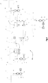
- the raw anodes 1 are formed in the anode production workshop 10. On leaving this workshop 10, an initial identification station 40 makes it possible to assign a digital signature to each anode.
- An optical reader 11 takes at least one raw image 50 of the green anode, this raw image 50 is digitally processed to obtain an optimized image 60 from which a digital signature is generated.
- a chronological IDA identification number of the anode is associated with the digital signature. If several raw images 50 of this anode are taken by the optical reader 11, or by several optical readers 11, then converted into digital signatures, the same identification number IDA is associated with all of these digital signatures.
- the green anode is judged to conform to the expected quality, it is conveyed to the pre-baking storage zone 12. If the anode is deemed to be non-compliant, it is routed to the rejection station 24.
- a conveyor 30 allows the transfer of the compliant green anodes from the pre-baking storage area 12 to the assembly station 13 in packages.
- a tracking identification station 41 makes it possible to identify the green anodes before they are packaged.
- An optical reader 11 takes at least one raw image 51 of the green anode, this raw image 51 is digitally processed to obtain an optimized image 61. The traceability system compares this image 61 with the optimized images 60 coming from the identification station. 40 initial in order to recognize the digital signature.
- a packet 14 is composed of four anodes.
- An internal identifier of an IDP packet is determined by the traceability system, for example from the IDA identification numbers of the anodes which constitute it.
- the movable bridge 15 takes charge of the packages 14 of anodes, their placement in the baking oven 16, then their recovery and deposit on an outlet conveyor 17.
- the conveyor 17 brings the packages 14 of cooked anodes to the disassembly station 18.
- a tracking identification station 42 makes it possible to recognize the digital signature.
- the system uses the positioning and time-stamping information of the handling means and lift 15 in oven 16 to ensure identification of anode 1.
- the anodes 1 are conveyed to the post-curing storage zone 19 if they comply with the required quality or to the zone 20 for rejecting the cured anode 1 if this cured anode is non-compliant.
- a tracking identification station 43 is also placed at the input of the post curing storage 19 to reinforce the tracking of the anodes, the optical reader 11 of this station 43 taking at least one raw image 53 of the anode. baked anode, and this raw image 53 is digitally processed to obtain an optimized image 63, which is compared at least with the optimized images 62 originating from the identification station 42 in order to recognize the digital signature which corresponds to it.
- the traceability system then identifies the IDA number of the anode using the digital signature.
- an identification station 44 makes it possible to '' identify the baked anodes before their sealing, again, by means of an optical reader 11 giving of each baked anode at least one raw image 54, which is digitally processed to obtain at least one optimized image 64 compared to at least the optimized images 63 in the previous identification station 43, to recognize the digital signature, linked to the identification number IDA associated with this anode.
- the electrolysis rods may have a marking 23 and an identification number IDR.
- the traceability system then marries this IDR identification number of each rod 22 to the IDA identification number of the anode which is assembled to this rod 22, to ensure the continuity of the traceability of the anodes to the electrolytic cells, then anode butts downstream of the tanks.
Landscapes
- Engineering & Computer Science (AREA)
- Chemical & Material Sciences (AREA)
- Mechanical Engineering (AREA)
- General Engineering & Computer Science (AREA)
- Chemical Kinetics & Catalysis (AREA)
- Electrochemistry (AREA)
- Materials Engineering (AREA)
- Metallurgy (AREA)
- Organic Chemistry (AREA)
- Electrolytic Production Of Metals (AREA)
- Testing And Monitoring For Control Systems (AREA)
Claims (18)
- Rückverfolgbarkeitsverfahren von kohlenstoffhaltigen Blöcken (1) von der Herstellung der Blöcke bis zu ihrer Versiegelung auf Elektrolysestäben, das geeignet ist, die Blöcke vor und nach Wärmebehandlung zu überwachen, und das in einer Anlage (100) zur Herstellung von kohlenstoffhaltigen Blöcken durchgeführt wird, umfassend:- ein Rückverfolgbarkeitssystem kohlenstoffhaltiger Blöcke (1) während ihrer Verarbeitung, ihres Transports und/oder ihrer Lagerung, mit:- mindestens einer sogenannten Erstidentifizierungsstation (40) zur Identifizierung mindestens eines kohlenstoffhaltigen Blocks (1), wobei die Erstidentifizierungsstation eine Vorrichtung zur Erstellung einer sogenannten Erstaufnahme von mindestens einem Teil der Außenfläche (1a) des kohlenstoffhaltigen Blocks (1) umfasst;- einem Signaturgenerator, der es ermöglicht, auf mindestens einer von der Erstaufnahmevorrichtung erstellten Aufnahme mindestens ein intrinsisches visuelles Merkmal zu erfassen, um auf der Grundlage dieses intrinsischen visuellen Merkmals mindestens eine digitale Signatur für den kohlenstoffhaltigen Block (1) zu erzeugen und aufzuzeichnen;- mindestens einer sogenannten Verfolgungsidentifizierungsstation (41, 42, 43, 44) für den kohlenstoffhaltigen Block (1), wobei die Verfolgungsidentifizierungsstation (41, 42, 43, 44) eine sogenannte Verfolgungsaufnahmevorrichtung zur Aufnahme mindestens eines Teils der Außenfläche (1a) des kohlenstoffhaltigen Blocks (1) umfasst;- mindestens einem Detektor, der es ermöglicht, auf mindestens einer von der Verfolgungsaufnahmevorrichtung erstellten Aufnahme zumindest teilweise das intrinsische visuelle Merkmal zu erfassen und die digitale Signatur des kohlenstoffhaltigen Blocks (1) zu erkennen, um den kohlenstoffhaltigen Block (1) zu identifizieren;- und, zwischen zwei Identifizierungsstationen (40, 41, 42, 43, 44) des Rückverfolgbarkeitssystems, mindestens eine Zone zur Verarbeitung und/oder Lagerung und/oder zum Transport der kohlenstoffhaltigen Blöcke (1),wobei das Verfahren umfasst:
und wobei das System keine speziell für die Erzeugung einer digitalen Signatur des kohlenstoffhaltigen Blocks (1) vorgesehene Markierungsvorrichtung aufweist,- mindestens eine Erstaufnahme mindestens eines Teils der Außenfläche (1a) mindestens eines kohlenstoffhaltigen Blocks (1) durch die Erstidentifizierungsstation;- Erfassen mindestens eines intrinsischen visuellen Merkmals auf der Erstaufnahme;- Erzeugen und Aufzeichnen mindestens einer digitalen Signatur für den kohlenstoffhaltigen Block (1) auf der Grundlage des intrinsischen visuellen Merkmals;- Erkennen der digitalen Signatur in mindestens einer Verfolgungsidentifizierungsstation (41, 42, 43, 44). - Rückverfolgbarkeitsverfahren nach Anspruch 1, umfassend:- Transport des kohlenstoffhaltigen Blocks (1) zu einer Verfolgungsidentifizieru ngsstation;- mindestens eine Verfolgungsaufnahme von mindestens einem Teil der Außenfläche des kohlenstoffhaltigen Blocks (1) durch eine Verfolgungsidentifizierungsstation (41, 42, 43, 44);- Erfassung des mindestens einen intrinsischen visuellen Merkmals auf der Verfolgungsaufnahme,- Erkennung der digitalen Signatur des kohlenstoffhaltigen Blocks (1).
- Rückverfolgbarkeitsverfahren nach Anspruch 1 oder Anspruch 2, wobei der Erkennungsschritt einen Vergleich zwischen dem intrinsischen visuellen Merkmal der Erstaufnahme und dem intrinsischen visuellen Merkmal der Verfolgungsaufnahme und eine Bestimmung eines Ähnlichkeitsgrades zwischen dem intrinsischen visuellen Merkmal der beiden Aufnahmen umfasst.
- Verfahren nach Anspruch 2 oder Anspruch 3, umfassend:- die Aufzeichnung der Position des kohlenstoffhaltigen Blocks (1) in mindestens einer Verarbeitungs- und/oder Lagerungs- und/oder Transportzone,- die Erkennung der digitalen Signatur umfasst dann eine Verknüpfung des intrinsischen visuellen Merkmals der Erstaufnahme mit dem intrinsischen visuellen Merkmal der Verfolgungsaufnahme durch Kenntnis der Position des kohlenstoffhaltigen Blocks (1) in der mindestens einen Verarbeitungs- und/oder Lagerungs- und/oder Transportzone.
- Verfahren nach einem der vorhergehenden Ansprüche, wobei das/die intrinsische(n) visuelle(n) Merkmal(e) auf der Oberfläche des kohlenstoffhaltigen Blocks (1) eine bestimmte geometrische Form umfasst/umfassen, die in die Textur des kohlenstoffhaltigen Blocks (1) eingeschrieben ist.
- Verfahren nach Anspruch 5, wobei das/die intrinsische(n) visuelle(n) Merkmal(e) auf der Oberfläche des kohlenstoffhaltigen Blocks (1) die Lage und/oder intrinsische Morphologie von Körnern (9a) umfasst/umfassen.
- Verfahren nach Anspruch 5 oder Anspruch 6, wobei das/die intrinsische(n) visuelle(n) Merkmal(e) auf der Oberfläche des kohlenstoffhaltigen Blocks (1) einen oder mehrere Reliefdefekte in einer die Körner (9a) umgebenden Bindermatrix (9b) umfasst/umfassen.
- Verfahren nach einem der vorhergehenden Ansprüche, wobei das (die) intrinsische(n) visuelle(n) Merkmal(e) auf der Oberfläche des kohlenstoffhaltigen Blocks zumindest teilweise Abdrücke (3) von Stopfen umfasst/umfassen, die während der Formgebung des kohlenstoffhaltigen Blocks (1) zur Bildung von Hohlräumen (2) verwendet wurden, die zur Aufnahme von Elektrolysestäben (22) bestimmt sind.
- Verfahren nach einem der vorhergehenden Ansprüche, wobei das/die intrinsische(n) visuelle(n) Merkmal(e) auf der Oberfläche des kohlenstoffhaltigen Blocks (1) eine einzigartige geometrische Form auf der Oberfläche des Blocks (1) umfasst/umfassen.
- Verfahren nach einem der vorhergehenden Ansprüche, wobei die Aufnahmevorrichtungen ein optisches Lesegerät (11) und eine Vorrichtung zur Aufzeichnung mindestens eines von dem optischen Lesegerät (11) erzeugten Rohbildes (50, 51, 52, 53, 54) umfassen.
- Verfahren nach Anspruch 10, wobei das Rückverfolgbarkeitssystem eine Vorrichtung zur digitalen Verarbeitung des mindestens einen Rohbildes umfasst, um ein optimiertes Bild (60, 61, 62, 63, 64) zu erzeugen, in dem das mindestens eine intrinsische visuelle Merkmal der Außenfläche (1a) des kohlenstoffhaltigen Blocks (1) hervorgehoben ist.
- Verfahren nach einem der vorhergehenden Ansprüche, wobei die Erstidentifizierungsstation (40) mit der Verfolgungsidentifizierungsstation (41, 42, 43, 44) zusammenfällt.
- Verfahren nach einem der vorhergehenden Ansprüche, umfassend eine Mehrzahl von Verfolgungsidentifizierungsstationen (41, 42, 43, 44).
- Verfahren nach einem der vorhergehenden Ansprüche, umfassend eine Positionsverfolgungsvorrichtung, die es ermöglicht, die Position des kohlenstoffhaltigen Blocks (1) zwischen zwei Identifizierungsstationen (40, 41, 42, 43, 44) zu erkennen und aufzuzeichnen.
- Verfahren nach Anspruch 14, umfassend eine Vorrichtung zur Zeitstempelung der Positionen des kohlenstoffhaltigen Blocks (1).
- Verfahren nach Anspruch 14 oder Anspruch 15, umfassend Mittel zum Fördern und Handhaben der kohlenstoffhaltigen Blöcke (1) für ihre Zusammenstellung zu Paketen (14) von kohlenstoffhaltigen Blöcken (1) zum Zweck ihrer Wärmebehandlung in einem Brennofen (16) und Mittel zum Zerlegen der Pakete (14) nach ihrer Wärmebehandlung, wobei die Positionsverfolgungsvorrichtung in der Lage ist, die Position jedes kohlenstoffhaltigen Blocks (1) in den Paketen (14) und die Position der Pakete (14) in dem Ofen (16) zu kennen.
- Verfahren nach einem der vorhergehenden Ansprüche, besonders angepasst an einen kohlenstoffhaltigen Block, der zur Herstellung von Aluminium durch Elektrolyse bestimmt ist.
- Verfahren nach einem der vorhergehenden Ansprüche, wobei mindestens eine Verarbeitungs- und/oder Lagerungs- und/oder Transportzone einen Brennofen (16) für die kohlenstoffhaltigen Blöcke (1) umfasst, wobei die Erstidentifizierungsstation (40) stromaufwärts des Brennofens (16) angeordnet ist, um die digitale Signatur auf einem rohen kohlenstoffhaltigen Block (1) zu definieren, und wobei mindestens eine Verfolgungsidentifizierungsstation (41, 42, 43, 44) stromabwärts des Ofens angeordnet ist, um die digitale Signatur auf dem gebrannten kohlenstoffhaltigen Block (1) zu erkennen.
Applications Claiming Priority (2)
| Application Number | Priority Date | Filing Date | Title |
|---|---|---|---|
| FR1755400A FR3067722B1 (fr) | 2017-06-15 | 2017-06-15 | Systeme et procede de tracabilite de blocs carbones |
| PCT/FR2018/051403 WO2018229441A1 (fr) | 2017-06-15 | 2018-06-14 | Systeme tracabilite de blocs carbones, installation de production de blocs carbones comprenant un tel systeme et procede de tracabilite de blocs carbones |
Publications (2)
| Publication Number | Publication Date |
|---|---|
| EP3638829A1 EP3638829A1 (de) | 2020-04-22 |
| EP3638829B1 true EP3638829B1 (de) | 2021-03-03 |
Family
ID=59746103
Family Applications (1)
| Application Number | Title | Priority Date | Filing Date |
|---|---|---|---|
| EP18748972.9A Active EP3638829B1 (de) | 2017-06-15 | 2018-06-14 | Verfahren zur verfolgbarkeit von kohlenstoffhaltigen blöcken |
Country Status (6)
| Country | Link |
|---|---|
| EP (1) | EP3638829B1 (de) |
| CN (1) | CN110997982B (de) |
| FR (1) | FR3067722B1 (de) |
| RU (1) | RU2769141C2 (de) |
| SA (1) | SA519410779B1 (de) |
| WO (1) | WO2018229441A1 (de) |
Families Citing this family (1)
| Publication number | Priority date | Publication date | Assignee | Title |
|---|---|---|---|---|
| CN111426212B (zh) * | 2020-04-17 | 2024-12-03 | 贵阳铝镁设计研究院有限公司 | 铝用阳极焙烧过程跟踪方法 |
Family Cites Families (6)
| Publication number | Priority date | Publication date | Assignee | Title |
|---|---|---|---|---|
| RU2123542C1 (ru) * | 1997-04-17 | 1998-12-20 | Ангарский электролизный химический комбинат | Способ получения коксовых пластин для фторных электролизеров |
| NO332378B1 (no) * | 2004-07-05 | 2012-09-10 | Norsk Elektro Optikk As | System for merking og avlesing |
| US8594417B2 (en) * | 2007-11-27 | 2013-11-26 | Alcoa Inc. | Systems and methods for inspecting anodes and smelting management relating to the same |
| WO2012168501A1 (es) * | 2011-06-10 | 2012-12-13 | Zincobre Ingeniería, S.L.U. | Sistema de verificación de la calidad de ánodos empleados en procesos electrolíticos |
| JP6326759B2 (ja) * | 2012-11-30 | 2018-05-23 | 株式会社リコー | 画像記録システム、画像書き換えシステム及び画像記録方法 |
| CN104694970A (zh) * | 2013-12-10 | 2015-06-10 | 沈阳铝镁设计研究院有限公司 | 预焙阳极碳块堆存自动跟踪方法 |
-
2017
- 2017-06-15 FR FR1755400A patent/FR3067722B1/fr active Active
-
2018
- 2018-06-14 EP EP18748972.9A patent/EP3638829B1/de active Active
- 2018-06-14 RU RU2020100906A patent/RU2769141C2/ru active
- 2018-06-14 WO PCT/FR2018/051403 patent/WO2018229441A1/fr not_active Ceased
- 2018-06-14 CN CN201880052448.4A patent/CN110997982B/zh active Active
-
2019
- 2019-12-10 SA SA519410779A patent/SA519410779B1/ar unknown
Non-Patent Citations (1)
| Title |
|---|
| None * |
Also Published As
| Publication number | Publication date |
|---|---|
| CN110997982B (zh) | 2022-01-11 |
| FR3067722A1 (fr) | 2018-12-21 |
| FR3067722B1 (fr) | 2019-07-26 |
| EP3638829A1 (de) | 2020-04-22 |
| RU2769141C2 (ru) | 2022-03-28 |
| CN110997982A (zh) | 2020-04-10 |
| RU2020100906A (ru) | 2021-07-15 |
| CA3063276A1 (fr) | 2018-12-20 |
| RU2020100906A3 (de) | 2021-07-26 |
| WO2018229441A1 (fr) | 2018-12-20 |
| SA519410779B1 (ar) | 2022-07-24 |
Similar Documents
| Publication | Publication Date | Title |
|---|---|---|
| CN103000756B (zh) | 光生伏打电池制造 | |
| US9812672B2 (en) | Systems, devices and methods for quality monitoring of deposited films in the formation of light emitting devices | |
| TWI477764B (zh) | 影像製作方法、基板檢查方法、記錄有用以執行該影像製作方法及該基板檢查方法之程式的記錄媒體與基板檢查裝置 | |
| JP4269005B2 (ja) | ガラス壜の検査装置 | |
| KR102399860B1 (ko) | 워크 처리 장치, 워크 반송 시스템 | |
| US20060045324A1 (en) | Method and device for preparing reference image in glass bottle inspection device | |
| TWI657725B (zh) | 影像檢查裝置及影像檢查方法 | |
| TW201523760A (zh) | 工件處理裝置、工件輸送系統 | |
| CN1633593A (zh) | 用于专门选择容器的方法和装置 | |
| JP2007218638A (ja) | 多結晶半導体ウエハの割れ検査装置および割れ検査方法 | |
| EP3638829A1 (de) | System zur verfolgbarkeit von kohlenstoffhaltigen blöcken, produktionsanlage für kohlenstoffhaltige blöcke mit einem solchen system und verfahren zur verfolgbarkeit von kohlenstoffhaltigen blöcken | |
| CN208092793U (zh) | 瓷层缺陷的检测平台 | |
| JP2012215519A (ja) | 錠剤検査装置及びptp包装機 | |
| US20180176549A1 (en) | Multi-view-angle image capturing device and multi-view-angle image inspection apparatus using the same | |
| JP3513903B2 (ja) | 検査装置及びその方法 | |
| CN102914551B (zh) | 玻璃基板检查系统以及玻璃基板的制造方法 | |
| CN117169227A (zh) | 插头的生产方法、装置、设备及存储介质 | |
| CA3063276C (fr) | Systeme tracabilite de blocs carbones, installation de production de blocs carbones comprenant un tel systeme et procede de tracabilite de blocs carbones | |
| CN120107194B (zh) | 一种基于图像检测的缺陷检测方法 | |
| JPH07286825A (ja) | バルブシートの間隙検査方法及び検査装置 | |
| TWI685042B (zh) | 旋轉晶粒分選系統及其分類方法 | |
| TW202518001A (zh) | 用於偵測缺陷之檢測系統和方法 | |
| CN116152212A (zh) | 一种汽车覆盖件表面凹坑、凸点和孔洞缺陷检测方法 | |
| CN116008277A (zh) | 一种基于机器视觉的塑料手机外壳缺陷检测方法 | |
| CN120961470A (zh) | 一种气门座圈定向分拣机构及方法 |
Legal Events
| Date | Code | Title | Description |
|---|---|---|---|
| STAA | Information on the status of an ep patent application or granted ep patent |
Free format text: STATUS: UNKNOWN |
|
| STAA | Information on the status of an ep patent application or granted ep patent |
Free format text: STATUS: THE INTERNATIONAL PUBLICATION HAS BEEN MADE |
|
| PUAI | Public reference made under article 153(3) epc to a published international application that has entered the european phase |
Free format text: ORIGINAL CODE: 0009012 |
|
| STAA | Information on the status of an ep patent application or granted ep patent |
Free format text: STATUS: REQUEST FOR EXAMINATION WAS MADE |
|
| 17P | Request for examination filed |
Effective date: 20191212 |
|
| AK | Designated contracting states |
Kind code of ref document: A1 Designated state(s): AL AT BE BG CH CY CZ DE DK EE ES FI FR GB GR HR HU IE IS IT LI LT LU LV MC MK MT NL NO PL PT RO RS SE SI SK SM TR |
|
| AX | Request for extension of the european patent |
Extension state: BA ME |
|
| DAV | Request for validation of the european patent (deleted) | ||
| DAX | Request for extension of the european patent (deleted) | ||
| GRAP | Despatch of communication of intention to grant a patent |
Free format text: ORIGINAL CODE: EPIDOSNIGR1 |
|
| STAA | Information on the status of an ep patent application or granted ep patent |
Free format text: STATUS: GRANT OF PATENT IS INTENDED |
|
| RIC1 | Information provided on ipc code assigned before grant |
Ipc: C25C 3/12 20060101AFI20201023BHEP Ipc: F27D 21/00 20060101ALI20201023BHEP Ipc: F27B 13/14 20060101ALI20201023BHEP Ipc: F27D 19/00 20060101ALI20201023BHEP |
|
| INTG | Intention to grant announced |
Effective date: 20201110 |
|
| GRAS | Grant fee paid |
Free format text: ORIGINAL CODE: EPIDOSNIGR3 |
|
| GRAA | (expected) grant |
Free format text: ORIGINAL CODE: 0009210 |
|
| STAA | Information on the status of an ep patent application or granted ep patent |
Free format text: STATUS: THE PATENT HAS BEEN GRANTED |
|
| AK | Designated contracting states |
Kind code of ref document: B1 Designated state(s): AL AT BE BG CH CY CZ DE DK EE ES FI FR GB GR HR HU IE IS IT LI LT LU LV MC MK MT NL NO PL PT RO RS SE SI SK SM TR |
|
| REG | Reference to a national code |
Ref country code: GB Ref legal event code: FG4D Free format text: NOT ENGLISH |
|
| REG | Reference to a national code |
Ref country code: CH Ref legal event code: EP Ref country code: AT Ref legal event code: REF Ref document number: 1367291 Country of ref document: AT Kind code of ref document: T Effective date: 20210315 |
|
| REG | Reference to a national code |
Ref country code: DE Ref legal event code: R096 Ref document number: 602018013487 Country of ref document: DE |
|
| REG | Reference to a national code |
Ref country code: IE Ref legal event code: FG4D Free format text: LANGUAGE OF EP DOCUMENT: FRENCH |
|
| REG | Reference to a national code |
Ref country code: NL Ref legal event code: FP |
|
| REG | Reference to a national code |
Ref country code: LT Ref legal event code: MG9D |
|
| PG25 | Lapsed in a contracting state [announced via postgrant information from national office to epo] |
Ref country code: LT Free format text: LAPSE BECAUSE OF FAILURE TO SUBMIT A TRANSLATION OF THE DESCRIPTION OR TO PAY THE FEE WITHIN THE PRESCRIBED TIME-LIMIT Effective date: 20210303 Ref country code: GR Free format text: LAPSE BECAUSE OF FAILURE TO SUBMIT A TRANSLATION OF THE DESCRIPTION OR TO PAY THE FEE WITHIN THE PRESCRIBED TIME-LIMIT Effective date: 20210604 Ref country code: FI Free format text: LAPSE BECAUSE OF FAILURE TO SUBMIT A TRANSLATION OF THE DESCRIPTION OR TO PAY THE FEE WITHIN THE PRESCRIBED TIME-LIMIT Effective date: 20210303 Ref country code: HR Free format text: LAPSE BECAUSE OF FAILURE TO SUBMIT A TRANSLATION OF THE DESCRIPTION OR TO PAY THE FEE WITHIN THE PRESCRIBED TIME-LIMIT Effective date: 20210303 Ref country code: BG Free format text: LAPSE BECAUSE OF FAILURE TO SUBMIT A TRANSLATION OF THE DESCRIPTION OR TO PAY THE FEE WITHIN THE PRESCRIBED TIME-LIMIT Effective date: 20210603 |
|
| REG | Reference to a national code |
Ref country code: AT Ref legal event code: MK05 Ref document number: 1367291 Country of ref document: AT Kind code of ref document: T Effective date: 20210303 |
|
| REG | Reference to a national code |
Ref country code: NO Ref legal event code: T2 Effective date: 20210303 |
|
| PG25 | Lapsed in a contracting state [announced via postgrant information from national office to epo] |
Ref country code: RS Free format text: LAPSE BECAUSE OF FAILURE TO SUBMIT A TRANSLATION OF THE DESCRIPTION OR TO PAY THE FEE WITHIN THE PRESCRIBED TIME-LIMIT Effective date: 20210303 Ref country code: PL Free format text: LAPSE BECAUSE OF FAILURE TO SUBMIT A TRANSLATION OF THE DESCRIPTION OR TO PAY THE FEE WITHIN THE PRESCRIBED TIME-LIMIT Effective date: 20210303 Ref country code: LV Free format text: LAPSE BECAUSE OF FAILURE TO SUBMIT A TRANSLATION OF THE DESCRIPTION OR TO PAY THE FEE WITHIN THE PRESCRIBED TIME-LIMIT Effective date: 20210303 Ref country code: SE Free format text: LAPSE BECAUSE OF FAILURE TO SUBMIT A TRANSLATION OF THE DESCRIPTION OR TO PAY THE FEE WITHIN THE PRESCRIBED TIME-LIMIT Effective date: 20210303 |
|
| PG25 | Lapsed in a contracting state [announced via postgrant information from national office to epo] |
Ref country code: AT Free format text: LAPSE BECAUSE OF FAILURE TO SUBMIT A TRANSLATION OF THE DESCRIPTION OR TO PAY THE FEE WITHIN THE PRESCRIBED TIME-LIMIT Effective date: 20210303 Ref country code: SM Free format text: LAPSE BECAUSE OF FAILURE TO SUBMIT A TRANSLATION OF THE DESCRIPTION OR TO PAY THE FEE WITHIN THE PRESCRIBED TIME-LIMIT Effective date: 20210303 Ref country code: CZ Free format text: LAPSE BECAUSE OF FAILURE TO SUBMIT A TRANSLATION OF THE DESCRIPTION OR TO PAY THE FEE WITHIN THE PRESCRIBED TIME-LIMIT Effective date: 20210303 Ref country code: EE Free format text: LAPSE BECAUSE OF FAILURE TO SUBMIT A TRANSLATION OF THE DESCRIPTION OR TO PAY THE FEE WITHIN THE PRESCRIBED TIME-LIMIT Effective date: 20210303 |
|
| PG25 | Lapsed in a contracting state [announced via postgrant information from national office to epo] |
Ref country code: IS Free format text: LAPSE BECAUSE OF FAILURE TO SUBMIT A TRANSLATION OF THE DESCRIPTION OR TO PAY THE FEE WITHIN THE PRESCRIBED TIME-LIMIT Effective date: 20210703 Ref country code: SK Free format text: LAPSE BECAUSE OF FAILURE TO SUBMIT A TRANSLATION OF THE DESCRIPTION OR TO PAY THE FEE WITHIN THE PRESCRIBED TIME-LIMIT Effective date: 20210303 Ref country code: PT Free format text: LAPSE BECAUSE OF FAILURE TO SUBMIT A TRANSLATION OF THE DESCRIPTION OR TO PAY THE FEE WITHIN THE PRESCRIBED TIME-LIMIT Effective date: 20210705 Ref country code: RO Free format text: LAPSE BECAUSE OF FAILURE TO SUBMIT A TRANSLATION OF THE DESCRIPTION OR TO PAY THE FEE WITHIN THE PRESCRIBED TIME-LIMIT Effective date: 20210303 |
|
| REG | Reference to a national code |
Ref country code: DE Ref legal event code: R097 Ref document number: 602018013487 Country of ref document: DE |
|
| PLBE | No opposition filed within time limit |
Free format text: ORIGINAL CODE: 0009261 |
|
| STAA | Information on the status of an ep patent application or granted ep patent |
Free format text: STATUS: NO OPPOSITION FILED WITHIN TIME LIMIT |
|
| PG25 | Lapsed in a contracting state [announced via postgrant information from national office to epo] |
Ref country code: AL Free format text: LAPSE BECAUSE OF FAILURE TO SUBMIT A TRANSLATION OF THE DESCRIPTION OR TO PAY THE FEE WITHIN THE PRESCRIBED TIME-LIMIT Effective date: 20210303 Ref country code: DK Free format text: LAPSE BECAUSE OF FAILURE TO SUBMIT A TRANSLATION OF THE DESCRIPTION OR TO PAY THE FEE WITHIN THE PRESCRIBED TIME-LIMIT Effective date: 20210303 Ref country code: MC Free format text: LAPSE BECAUSE OF FAILURE TO SUBMIT A TRANSLATION OF THE DESCRIPTION OR TO PAY THE FEE WITHIN THE PRESCRIBED TIME-LIMIT Effective date: 20210303 Ref country code: ES Free format text: LAPSE BECAUSE OF FAILURE TO SUBMIT A TRANSLATION OF THE DESCRIPTION OR TO PAY THE FEE WITHIN THE PRESCRIBED TIME-LIMIT Effective date: 20210303 |
|
| 26N | No opposition filed |
Effective date: 20211206 |
|
| PG25 | Lapsed in a contracting state [announced via postgrant information from national office to epo] |
Ref country code: SI Free format text: LAPSE BECAUSE OF FAILURE TO SUBMIT A TRANSLATION OF THE DESCRIPTION OR TO PAY THE FEE WITHIN THE PRESCRIBED TIME-LIMIT Effective date: 20210303 |
|
| REG | Reference to a national code |
Ref country code: BE Ref legal event code: MM Effective date: 20210630 |
|
| PG25 | Lapsed in a contracting state [announced via postgrant information from national office to epo] |
Ref country code: LU Free format text: LAPSE BECAUSE OF NON-PAYMENT OF DUE FEES Effective date: 20210614 |
|
| PG25 | Lapsed in a contracting state [announced via postgrant information from national office to epo] |
Ref country code: IT Free format text: LAPSE BECAUSE OF FAILURE TO SUBMIT A TRANSLATION OF THE DESCRIPTION OR TO PAY THE FEE WITHIN THE PRESCRIBED TIME-LIMIT Effective date: 20210303 Ref country code: IE Free format text: LAPSE BECAUSE OF NON-PAYMENT OF DUE FEES Effective date: 20210614 |
|
| PG25 | Lapsed in a contracting state [announced via postgrant information from national office to epo] |
Ref country code: IS Free format text: LAPSE BECAUSE OF FAILURE TO SUBMIT A TRANSLATION OF THE DESCRIPTION OR TO PAY THE FEE WITHIN THE PRESCRIBED TIME-LIMIT Effective date: 20210703 |
|
| PG25 | Lapsed in a contracting state [announced via postgrant information from national office to epo] |
Ref country code: BE Free format text: LAPSE BECAUSE OF NON-PAYMENT OF DUE FEES Effective date: 20210630 |
|
| GBPC | Gb: european patent ceased through non-payment of renewal fee |
Effective date: 20220614 |
|
| PG25 | Lapsed in a contracting state [announced via postgrant information from national office to epo] |
Ref country code: GB Free format text: LAPSE BECAUSE OF NON-PAYMENT OF DUE FEES Effective date: 20220614 |
|
| PG25 | Lapsed in a contracting state [announced via postgrant information from national office to epo] |
Ref country code: CY Free format text: LAPSE BECAUSE OF FAILURE TO SUBMIT A TRANSLATION OF THE DESCRIPTION OR TO PAY THE FEE WITHIN THE PRESCRIBED TIME-LIMIT Effective date: 20210303 |
|
| PG25 | Lapsed in a contracting state [announced via postgrant information from national office to epo] |
Ref country code: HU Free format text: LAPSE BECAUSE OF FAILURE TO SUBMIT A TRANSLATION OF THE DESCRIPTION OR TO PAY THE FEE WITHIN THE PRESCRIBED TIME-LIMIT; INVALID AB INITIO Effective date: 20180614 |
|
| PG25 | Lapsed in a contracting state [announced via postgrant information from national office to epo] |
Ref country code: MK Free format text: LAPSE BECAUSE OF FAILURE TO SUBMIT A TRANSLATION OF THE DESCRIPTION OR TO PAY THE FEE WITHIN THE PRESCRIBED TIME-LIMIT Effective date: 20210303 |
|
| PG25 | Lapsed in a contracting state [announced via postgrant information from national office to epo] |
Ref country code: MT Free format text: LAPSE BECAUSE OF FAILURE TO SUBMIT A TRANSLATION OF THE DESCRIPTION OR TO PAY THE FEE WITHIN THE PRESCRIBED TIME-LIMIT Effective date: 20210303 |
|
| PGFP | Annual fee paid to national office [announced via postgrant information from national office to epo] |
Ref country code: NL Payment date: 20250520 Year of fee payment: 8 |
|
| PGFP | Annual fee paid to national office [announced via postgrant information from national office to epo] |
Ref country code: DE Payment date: 20250520 Year of fee payment: 8 |
|
| PGFP | Annual fee paid to national office [announced via postgrant information from national office to epo] |
Ref country code: NO Payment date: 20250522 Year of fee payment: 8 |
|
| PGFP | Annual fee paid to national office [announced via postgrant information from national office to epo] |
Ref country code: FR Payment date: 20250520 Year of fee payment: 8 |
|
| PGFP | Annual fee paid to national office [announced via postgrant information from national office to epo] |
Ref country code: CH Payment date: 20250701 Year of fee payment: 8 |
|
| PG25 | Lapsed in a contracting state [announced via postgrant information from national office to epo] |
Ref country code: TR Free format text: LAPSE BECAUSE OF FAILURE TO SUBMIT A TRANSLATION OF THE DESCRIPTION OR TO PAY THE FEE WITHIN THE PRESCRIBED TIME-LIMIT Effective date: 20210303 |