EP3638017B1 - Infrastrukturanordnung für einen nutztierstall und verfahren zur bereitstellung eines solchen - Google Patents
Infrastrukturanordnung für einen nutztierstall und verfahren zur bereitstellung eines solchen Download PDFInfo
- Publication number
- EP3638017B1 EP3638017B1 EP18734775.2A EP18734775A EP3638017B1 EP 3638017 B1 EP3638017 B1 EP 3638017B1 EP 18734775 A EP18734775 A EP 18734775A EP 3638017 B1 EP3638017 B1 EP 3638017B1
- Authority
- EP
- European Patent Office
- Prior art keywords
- autonomous
- position determination
- vehicle
- shed
- shed vehicle
- Prior art date
- Legal status (The legal status is an assumption and is not a legal conclusion. Google has not performed a legal analysis and makes no representation as to the accuracy of the status listed.)
- Active
Links
Images



Classifications
-
- A—HUMAN NECESSITIES
- A01—AGRICULTURE; FORESTRY; ANIMAL HUSBANDRY; HUNTING; TRAPPING; FISHING
- A01K—ANIMAL HUSBANDRY; AVICULTURE; APICULTURE; PISCICULTURE; FISHING; REARING OR BREEDING ANIMALS, NOT OTHERWISE PROVIDED FOR; NEW BREEDS OF ANIMALS
- A01K31/00—Housing birds
- A01K31/04—Dropping-boards; Devices for removing excrement
-
- A—HUMAN NECESSITIES
- A01—AGRICULTURE; FORESTRY; ANIMAL HUSBANDRY; HUNTING; TRAPPING; FISHING
- A01K—ANIMAL HUSBANDRY; AVICULTURE; APICULTURE; PISCICULTURE; FISHING; REARING OR BREEDING ANIMALS, NOT OTHERWISE PROVIDED FOR; NEW BREEDS OF ANIMALS
- A01K1/00—Housing animals; Equipment therefor
- A01K1/01—Removal of dung or urine ; Removal of manure from stables
-
- A—HUMAN NECESSITIES
- A01—AGRICULTURE; FORESTRY; ANIMAL HUSBANDRY; HUNTING; TRAPPING; FISHING
- A01K—ANIMAL HUSBANDRY; AVICULTURE; APICULTURE; PISCICULTURE; FISHING; REARING OR BREEDING ANIMALS, NOT OTHERWISE PROVIDED FOR; NEW BREEDS OF ANIMALS
- A01K1/00—Housing animals; Equipment therefor
- A01K1/0005—Stable partitions
- A01K1/0017—Gates, doors
- A01K1/0029—Crowding gates or barriers
-
- A—HUMAN NECESSITIES
- A01—AGRICULTURE; FORESTRY; ANIMAL HUSBANDRY; HUNTING; TRAPPING; FISHING
- A01K—ANIMAL HUSBANDRY; AVICULTURE; APICULTURE; PISCICULTURE; FISHING; REARING OR BREEDING ANIMALS, NOT OTHERWISE PROVIDED FOR; NEW BREEDS OF ANIMALS
- A01K1/00—Housing animals; Equipment therefor
- A01K1/01—Removal of dung or urine ; Removal of manure from stables
- A01K1/0128—Removal of dung or urine ; Removal of manure from stables by means of scrapers or the like moving continuously
-
- A—HUMAN NECESSITIES
- A01—AGRICULTURE; FORESTRY; ANIMAL HUSBANDRY; HUNTING; TRAPPING; FISHING
- A01K—ANIMAL HUSBANDRY; AVICULTURE; APICULTURE; PISCICULTURE; FISHING; REARING OR BREEDING ANIMALS, NOT OTHERWISE PROVIDED FOR; NEW BREEDS OF ANIMALS
- A01K1/00—Housing animals; Equipment therefor
- A01K1/015—Floor coverings, e.g. bedding-down sheets ; Stable floors
-
- A—HUMAN NECESSITIES
- A01—AGRICULTURE; FORESTRY; ANIMAL HUSBANDRY; HUNTING; TRAPPING; FISHING
- A01K—ANIMAL HUSBANDRY; AVICULTURE; APICULTURE; PISCICULTURE; FISHING; REARING OR BREEDING ANIMALS, NOT OTHERWISE PROVIDED FOR; NEW BREEDS OF ANIMALS
- A01K15/00—Devices for taming animals, e.g. nose-rings or hobbles; Devices for overturning animals in general; Training or exercising equipment; Covering boxes
- A01K15/02—Training or exercising equipment, e.g. mazes or labyrinths for animals ; Electric shock devices; Toys specially adapted for animals
-
- A—HUMAN NECESSITIES
- A01—AGRICULTURE; FORESTRY; ANIMAL HUSBANDRY; HUNTING; TRAPPING; FISHING
- A01K—ANIMAL HUSBANDRY; AVICULTURE; APICULTURE; PISCICULTURE; FISHING; REARING OR BREEDING ANIMALS, NOT OTHERWISE PROVIDED FOR; NEW BREEDS OF ANIMALS
- A01K29/00—Other apparatus for animal husbandry
-
- A—HUMAN NECESSITIES
- A01—AGRICULTURE; FORESTRY; ANIMAL HUSBANDRY; HUNTING; TRAPPING; FISHING
- A01K—ANIMAL HUSBANDRY; AVICULTURE; APICULTURE; PISCICULTURE; FISHING; REARING OR BREEDING ANIMALS, NOT OTHERWISE PROVIDED FOR; NEW BREEDS OF ANIMALS
- A01K39/00—Feeding or drinking appliances for poultry or other birds
- A01K39/01—Feeding devices
-
- A—HUMAN NECESSITIES
- A01—AGRICULTURE; FORESTRY; ANIMAL HUSBANDRY; HUNTING; TRAPPING; FISHING
- A01K—ANIMAL HUSBANDRY; AVICULTURE; APICULTURE; PISCICULTURE; FISHING; REARING OR BREEDING ANIMALS, NOT OTHERWISE PROVIDED FOR; NEW BREEDS OF ANIMALS
- A01K45/00—Other aviculture appliances, e.g. devices for determining whether a bird is about to lay
-
- A—HUMAN NECESSITIES
- A01—AGRICULTURE; FORESTRY; ANIMAL HUSBANDRY; HUNTING; TRAPPING; FISHING
- A01K—ANIMAL HUSBANDRY; AVICULTURE; APICULTURE; PISCICULTURE; FISHING; REARING OR BREEDING ANIMALS, NOT OTHERWISE PROVIDED FOR; NEW BREEDS OF ANIMALS
- A01K5/00—Feeding devices for stock or game ; Feeding wagons; Feeding stacks
- A01K5/02—Automatic devices
- A01K5/0266—Automatic devices with stable trolleys, e.g. suspended
-
- A—HUMAN NECESSITIES
- A01—AGRICULTURE; FORESTRY; ANIMAL HUSBANDRY; HUNTING; TRAPPING; FISHING
- A01K—ANIMAL HUSBANDRY; AVICULTURE; APICULTURE; PISCICULTURE; FISHING; REARING OR BREEDING ANIMALS, NOT OTHERWISE PROVIDED FOR; NEW BREEDS OF ANIMALS
- A01K5/00—Feeding devices for stock or game ; Feeding wagons; Feeding stacks
- A01K5/02—Automatic devices
- A01K5/0291—Automatic devices with timing mechanisms, e.g. pet feeders
-
- B—PERFORMING OPERATIONS; TRANSPORTING
- B60—VEHICLES IN GENERAL
- B60P—VEHICLES ADAPTED FOR LOAD TRANSPORTATION OR TO TRANSPORT, TO CARRY, OR TO COMPRISE SPECIAL LOADS OR OBJECTS
- B60P3/00—Vehicles adapted to transport, to carry or to comprise special loads or objects
- B60P3/04—Vehicles adapted to transport, to carry or to comprise special loads or objects for transporting animals
-
- G—PHYSICS
- G05—CONTROLLING; REGULATING
- G05D—SYSTEMS FOR CONTROLLING OR REGULATING NON-ELECTRIC VARIABLES
- G05D1/00—Control of position, course, altitude or attitude of land, water, air or space vehicles, e.g. using automatic pilots
- G05D1/02—Control of position or course in two dimensions
- G05D1/021—Control of position or course in two dimensions specially adapted to land vehicles
- G05D1/0257—Control of position or course in two dimensions specially adapted to land vehicles using a radar
-
- G—PHYSICS
- G05—CONTROLLING; REGULATING
- G05D—SYSTEMS FOR CONTROLLING OR REGULATING NON-ELECTRIC VARIABLES
- G05D1/00—Control of position, course, altitude or attitude of land, water, air or space vehicles, e.g. using automatic pilots
- G05D1/02—Control of position or course in two dimensions
- G05D1/021—Control of position or course in two dimensions specially adapted to land vehicles
- G05D1/0268—Control of position or course in two dimensions specially adapted to land vehicles using internal positioning means
- G05D1/027—Control of position or course in two dimensions specially adapted to land vehicles using internal positioning means comprising intertial navigation means, e.g. azimuth detector
-
- G—PHYSICS
- G05—CONTROLLING; REGULATING
- G05D—SYSTEMS FOR CONTROLLING OR REGULATING NON-ELECTRIC VARIABLES
- G05D1/00—Control of position, course, altitude or attitude of land, water, air or space vehicles, e.g. using automatic pilots
- G05D1/02—Control of position or course in two dimensions
- G05D1/021—Control of position or course in two dimensions specially adapted to land vehicles
- G05D1/0268—Control of position or course in two dimensions specially adapted to land vehicles using internal positioning means
- G05D1/0272—Control of position or course in two dimensions specially adapted to land vehicles using internal positioning means comprising means for registering the travel distance, e.g. revolutions of wheels
Definitions
- the invention relates to an infrastructure arrangement for a livestock barn and a method for providing infrastructure for a livestock barn.
- Infrastructure arrangements for livestock stalls and methods for providing infrastructure in livestock stalls are known and also include, for example, autonomous stable vehicles.
- US 2015/0250137 A1 discloses an animal feeding vehicle comprising a motion control system, a GPS receiver for generating a first set of parameters including location information, a proximity sensor for generating a second set of parameters including spatial information, a position sensor for generating a third set of parameters including motion information, a feeding system including a Feeding control system for feeding animals based on a fourth set of parameters.
- GB 2529166 A discloses an animal feces collecting device comprising an animal feces collecting robot having a body, a drive system for propelling the body along a ground surface, a navigation system for self-guiding the body within an environment in which animal feces are to be collected, a detection system for identifying animal feces, a A loading arrangement for collecting animal manure, an unloading arrangement for discarding collected animal manure and a control system for controlling the operations of the animal manure collecting robot.
- US 2002/0049522 A1 discloses a multifunctional mobile device that is capable of performing a multitude of tasks safely, quietly, without pollution and out of sight of its owner. Such tasks can include mowing the lawn, manuring and edging, vacuuming, waxing and polishing, or shampooing carpets.
- the infrastructure arrangement described here has an autonomous stable vehicle with a control unit.
- the autonomous stable vehicle also has an optics-free position determination device.
- An optics-free position determining device can also be referred to as a flare.
- the infrastructure arrangement further comprises a stationary position determination network with several optics-free position determination network points. In the case of an operationally ready arrangement of the infrastructure arrangement in a livestock barn, these can preferably be arranged spatially distributed in the livestock barn.
- the control unit of the autonomous stable vehicle is designed to generate a schedule for the autonomous vehicle as a function of information from the position determining device and a data transmission unit of the infrastructure arrangement.
- the position determination by means of the position determination device of the autonomous stable vehicle and the stationary position determination network is preferably done without optics.
- Optics-free is understood here in particular as a position determination that is not based on an optical method, that is, for example, does not provide for image recognition, light barriers or the like.
- Optics-free is also understood here to mean, in particular, a position determination that works without optical elements, in particular without lenses and / or light.
- the autonomous stable vehicle can preferably have two, three or more optics-free position determination devices. This way you can provide an orientation and / or a vector of the stall vehicle can also be determined without the stall vehicle moving, that is to say when the stall vehicle is stationary.
- An optics-free position determination can preferably take place by means of a flare network.
- An optics-free position determination can include a position determination in which a direct line of sight exists between the position determination device of the autonomous stable vehicle and one or more optics-free position determination network points that is not obstructed, for example, by stable installations. Such a direct line of sight between the position determination device of the autonomous stable vehicle and one or more of the position determination network points of the position determination network can also be preferred in the case of position determination without optics.
- Position determination network points are preferably arranged in such a way that there is a direct line of sight between the position determination device of the autonomous stable vehicle and at least one, preferably two, three, four or five of the position determination network points of the position determination network, regardless of where the stable vehicle is in the stable.
- the autonomous stable vehicle also has a charging interface in order to be able to charge the drive at a charging station of the infrastructure arrangement.
- the autonomous stable vehicle also has a coupling device for releasably attaching various functional units.
- a functional unit can in principle be arranged on the coupling device, but this can be removed and replaced by another functional unit.
- the autonomous stable vehicle can preferably be operated with or without a functional unit, in particular also with changing functional units.
- the releasable fastening of a functional unit to the coupling device can also be referred to as equipping.
- the infrastructure arrangement has at least one loading station in which the autonomous stable vehicle can be coupled with a functional unit and / or in which the autonomous stable vehicle can be equipped with work materials.
- the data transmission unit of the infrastructure arrangement is preferably for data exchange with the autonomous stable vehicle, in particular its control unit, and / or designed with a central computer.
- information on work orders to be carried out by the autonomous stable vehicle can be sent from a central computer to the control unit of the autonomous stable vehicle via the data transmission unit.
- information about work orders that have been carried out can preferably be transmitted from the control unit of the autonomous stable vehicle to a central computer via the data transmission unit.
- a schedule for the autonomous stable vehicle can preferably include a planned route and / or work to be carried out at certain positions and / or work material to be picked up and / or deployed and / or functional units etc. to be used.
- the infrastructure arrangement described here enables largely autonomous planning for the autonomous stable vehicle.
- an operator of a livestock stable can generate work orders to be carried out on a central computer and transmit them to the autonomous stable vehicle via the data transmission unit.
- a schedule can be generated via the link with current position data of the autonomous stable vehicle, which, based on the current position of the stable vehicle, enables the pending work orders to be processed as efficiently as possible.
- suitable planning algorithms are preferably stored in the control unit.
- a synchronization of data and information with a central computer and / or a network is preferably also possible.
- the equipping station and / or the autonomous stable vehicle are preferably designed such that the autonomous stable vehicle can be equipped with different functional units and / or Work materials take place autonomously and / or automatically, with preferably no user intervention at the assembly station being required.
- the actions of a user are preferably limited to the specification of a work order, for example from a central computer and / or via a man-machine interface, for example the control unit of the autonomous stable vehicle.
- the timetable generated by the control unit of the autonomous stable vehicle preferably contains the information about which usage units and / or work materials are required, so that these can be automatically and / or autonomously picked up by the autonomous stable vehicle at the loading station.
- the control unit of the autonomous stable vehicle can be formed on the autonomous stable vehicle itself or can also be arranged at a distance from it.
- the control unit of the autonomous stable vehicle can be arranged entirely or partially in the data transmission unit and / or in a central computer.
- the optics-free position determination device is designed to determine a position of the autonomous stable vehicle within the livestock stable in communication with the position determination network.
- the optics-free position determination device is preferably designed to interact with the stationary position determination network, in particular its position determination network points, in order to determine a position of the autonomous stable vehicle. Since the autonomous stable vehicle can be moved by means of a drive within the livestock stable, it is advantageous to determine the position of the stable vehicle, in particular, for example, for navigation and / or for task planning.
- the position determination device and / or at least one of the position determination network points and / or the position determination network has an ultra-broadband unit and / or an RFID unit and / or a radio unit and / or an odometer and / or an inertial sensor system and / or a radar sensor system .
- a distance in the vertical direction between at least one of the position determination network points and / or several or all position determination network points and / or the position determination network and the optics-free position determination device of the autonomous stable vehicle is smaller than ten times an extension in the vertical direction of the autonomous stable vehicle, in particular five times an extension in the vertical direction of the autonomous stable vehicle, and / or is smaller than 3m, in particular smaller than 1.5m.
- One or more of these different optics-free position determinations are preferred, since navigation within a livestock barn is usually a major challenge, on the one hand due to the large amount of dust inside a livestock barn, which usually excludes optics-based position determinations or at least makes it significantly more difficult, or due to the building installations , such as the steel grilles of aviaries for poultry. These usually shield a large number of frequency ranges, including the usual frequency ranges for GPS (approx. 1.2 GHz or 1.5 GHz), WLAN (2.4 to 2.5 GHz), etc.). A comprehensive availability of a positioning network in the stable is therefore difficult.
- Ultra-broadband technology has proven to be particularly suitable for determining the position in a livestock stable, in particular with a frequency between 3 and 11 GHz, in particular between 3.1 and 10.6 GHz.
- An extension in the vertical direction of the autonomous stable vehicle is preferably dimensioned in such a way that the autonomous stable vehicle is smaller than a clear height under stable fittings.
- an extension in the vertical direction of the autonomous stable vehicle is less than 450 mm, and / or less than 400 mm, and / or less than 350 mm, and / or less than 300 mm, and / or less than 250 mm, and / or less 200 mm.
- the position determination network points of the position determination network are preferably arranged above head height of the livestock and / or below a ceiling of a livestock barn.
- the position determination network points are preferably located in the vertical direction in one or two, preferably horizontal, planes. In this way, shadowing effects can be minimized and, furthermore, the number of required positioning network points can be reduced.
- the position determination network points are preferably arranged in the vertical direction at a maximum at the level of an upper end of the stable installations, in particular of poultry aviaries. In particular, it is preferred that the position determination network points are spaced from a livestock barn ceiling and / or an upper end of the livestock barn walls in the vertical direction downwards, by at least 1 m.
- Position determination network points in the vertical direction are arranged at most at the level of a lower animal living area of the stable installations, in particular at maximum at the level of a lower animal living area of a poultry aviary. Particularly preferred is the arrangement of the position determination network points in the vertical direction at the most at the level of a lower floor of the barn installations and above a livestock height, the livestock height preferably being the height that the livestock on the barn floor do not usually exceed with normal behavior, for example poultry their head height.
- the autonomous stable vehicle in particular the control unit, has a, preferably electronic, map of the livestock barn and / or an area surrounding the livestock barn, for example an entire livestock barn system.
- the accuracy of this map can preferably be generated and / or increased during operation and / or during commissioning.
- the map can serve as basic assumption or input information and can preferably be validated and / or improved during operation, in particular while driving the stable vehicle. This can be done, for example, by the stable vehicle recognizing obstacles, registering them and comparing them with the map.
- a validation function which is preferably combined with obstacle detection and / or collision detection, various advantages and functions result.
- the validation and / or improvement of the, preferably electronic, card can take place during commissioning and / or as a so-called plug-and-play solution directly in the livestock stable on site.
- a user can bring out material for the farm animals.
- the autonomous stable vehicle can also bring activity material for the animals, for example by transmitting a corresponding work order to the stable vehicle.
- the activity material is usually in the corridors of a livestock shed.
- the user can note the location of the activity material on the card so that this is registered as a temporary obstacle and the autonomous stable vehicle can accordingly bypass these areas with the activity material released, in particular during a specified period in which the activity material is usually used up and / or dismantled.
- This makes it possible to bypass obstacles, which lead to significant time savings can in comparison to known systems in which a stable vehicle drives through an area and drives back to the obstacle with each passage and has to perform a detour, for example according to the presented detour patterns.
- a user notes that activity material or the like has been brought out on the card can also be interpreted as a work order for the autonomous stable vehicle. For example, a user can note on a map the position at which the autonomous stable vehicle is to automatically deploy activity material.
- a user has the option of specifying an expiry date for an obstacle after the (temporary) obstacle is likely to no longer exist, for example by using up and / or dismantling activity material by the farm animals.
- the infrastructure arrangement is designed, preferably regularly, to generate reports with reports on the livestock stable, for example with a report on obstacles, in which a user can then assign a corresponding expiration date.
- a corresponding classification of obstacles can also take place on site in the livestock barn, in which the user carries a mobile device, for example a smartphone, with him, which displays a map with the positions of the obstacles and via which a user can directly obtain further information such as for example, expiration dates, can store these obstacles.
- Such reports can serve, for example, as a visual summary and give a user, in particular regularly, feedback on the state of the livestock barn.
- This can preferably be stored by a user and / or stored in the autonomous stable vehicle according to an algorithm and / or a heuristic.
- These classifications can preferably also be edited by a user using a mobile terminal on site in the livestock stable.
- An obstacle can be classified according to time, expiration date, size and / or position, for example.
- a user can assign a certain problem to a certain position, such as hard litter, and mark this on the electronic map via the mobile terminal and generate a work order for this.
- the autonomous stable vehicle will preferably generate a schedule as a function of this work order received via the data transmission unit and its current position, which initially provides for a litter cutter to be picked up at the loading station and then includes milling of the hard litter at the marked position.
- a timetable generated by the control unit of the autonomous stable vehicle can preferably be changed and / or expanded by a user, in particular also in relation to a specific problem. For example, in the example described here, a user can plan to mill several times at different times.
- control unit is preferably designed to generate a statistical evaluation of the success of work orders and / or suggestions for their optimization.
- a statistical evaluation can preferably be displayed and / or further processed on a mobile terminal, at a station in the livestock stable, on a central computer and / or in a network, in particular, for example, to be linked to further external data, for example to make automatic recommendations for certain To generate problems.
- a preferred development is characterized in that the drive is an essentially emission-free drive, in particular an electric drive.
- ballast station for arranging additional weights on the autonomous stable vehicle.
- ballasting can be preferred in particular for certain tasks and / or certain areas of application of the autonomous stable vehicle.
- the ballasting preferably takes place in an essentially automated manner as a function of information from the position determination device and in particular from the data transmission unit.
- the details described here for automated assembly apply mutatis mutandis to the preferably automatic ballasting.
- the schedule includes a sequence and / or a dwell time for approaching and / or staying at work areas.
- the data transmission unit comprises a man-machine interface and / or a data interface which is designed to receive information about tasks to be performed by the autonomous stable vehicle and / or to supply information about tasks performed by the autonomous stable vehicle to transfer.
- Another preferred development is characterized in that the data transmission unit and the control unit of the autonomous stable vehicle are designed for a contact-based and / or a line-based exchange of information with one another.
- the data transmission unit and the control unit of the autonomous stable vehicle can be designed for a contact-free and / or line-free exchange of information with one another.
- the design for a contact-based and / or line-based exchange of information between the data transmission unit and the control unit of the autonomous stable vehicle is preferred.
- the information exchange between the data transmission unit and the control unit of the Autonomous stable vehicle take place at one of the stations described when the autonomous stable vehicle is at such a station.
- a contact-based and / or wire-based exchange of information helps to reduce the stress on farm animals from wireless data transmission.
- a low transmission power from transmitters located in the livestock stable is preferred in order to keep a corresponding exposure to the livestock as low as possible.
- the autonomous stable vehicle can be essentially offline while a schedule is being processed and, for example, can process work orders and collect information.
- the autonomous stable vehicle can exchange contact-based and / or wired information with the data transmission unit and, for example, download new work orders and / or upload and for example import it into a central database and / or compare it with target data or the like.
- Software updates for the autonomous stable vehicle can preferably also take place in this way.
- control unit of the autonomous stable vehicle is designed to receive a callback order from the data transmission unit in a non-contact and / or non-wired manner and / or to transmit position and / or status information to the data transmission unit in a non-contact and / or non-wired manner.
- the autonomous stable vehicle in particular the position determination device and / or the control unit of the autonomous stable vehicle, is designed to receive a callback order from the position determination network in a non-contact and / or non-wired manner.
- This embodiment is particularly preferred in order to be able to bring about a premature interruption of a schedule of the autonomous stable vehicle in that the stable vehicle can be called back, for example to one of the stations described here or another, preferably predetermined, position.
- the non-contact and / or wire-bound one enables Line-independent transmission of a recall order and / or position information and / or status information minimal communication with the autonomous stable vehicle. In this way it can be determined, for example, where the stable vehicle is located and / or in what state the drive is, for example, in particular with regard to the charge level.
- Communication between the position determination device and the position determination network is preferably possible independently of contact-based and / or non-contact communication between the data transmission unit and the control unit.
- Contact-based and / or wire-based communication between the data transmission unit and the control unit is also preferred, since in particular the stable fittings, which are mostly made of metal, and / or the steel walls, which are usually also made of metal, enable contact-based and / or wire-free communication between the data transmission unit and the control unit make it more difficult and expensive, provided that such a facility can be implemented across the board in the livestock stable.
- the autonomous stable vehicle comprises a storage device for receiving objects to be transported.
- the callback function can also be used, for example, if a user needs the autonomous stable vehicle to follow the user at a distance, that is to say performs a “butler function”.
- the control unit is preferably designed, one To interrupt the timetable of the autonomous stable vehicle for such a butler function and to resume it after the butler function has ended.
- the autonomous stable vehicle can follow the user and preferably transport objects onto its storage device, such as tools, spare parts, food, work materials, etc. required by the user.
- the autonomous stable vehicle thus offers a user a mobile storage area and / or a mobile service cart and / or convenient load transport.
- an image evaluation and / or a field strength measurement and / or RFID technology and / or NFC technology can be used, in particular for example also in connection with a mobile terminal to be carried by the user.
- At least one lock is provided for the arrangement between two or more areas where livestock are staying, the lock being designed for the autonomous stable vehicle to pass through.
- the at least one lock comprises a lift unit for moving the autonomous stable vehicle in the vertical direction, and / or a cleaning device for cleaning and / or disinfecting the autonomous stable vehicle or parts thereof, and / or a charging station for Charging the drive of the autonomous stable vehicle includes, and / or includes a data interface for coupling to the data transmission unit.
- the at least one sluice comprises a passage obstacle for livestock.
- the sluice includes one or more obstacles for farm animals to block and / or reduce the passage for farm animals.
- a passage obstacle can, for example, be a lamella curtain and / or a cattle fence.
- a cattle lattice can preferably be constructed as a lattice of lattice elements arranged in parallel, such as rods and / or pipes and / or rails, the lattice elements preferably being made of metal or being able to have metal. Gaps of such a size are preferably provided between the grid elements that the livestock cannot enter and / or cross the cattle fence, whereas a user and / or the autonomous stable vehicle can enter and / or cross the cattle fence.
- the two or more livestock areas can be arranged on one level in the livestock barn and / or distributed over different levels, in particular floors / storeys, of a barn building.
- the two or more livestock areas can also be located in different buildings of a livestock barn system. Outside livestock areas can also be located between the steel buildings of a livestock barn.
- one or more areas are designated as stable vehicle areas in which preferably only the stable vehicle is present.
- the position of locks is also recorded in the, preferably electronic, map.
- the sluice and / or the passage obstacle is preferably designed in such a way that only the autonomous stable vehicle can use the sluice to change between the livestock areas.
- the lock comprises a lift unit for moving the autonomous stable vehicle in the vertical direction.
- the lift unit can be designed as a lift and / or paternoster, for example.
- the lock can be designed, for example, as a light lock, for example by means of a laser, and / or as a water lock.
- the lock includes additional functions.
- a cleaning device can be provided that completely covers the autonomous stable vehicle or partially cleans and / or disinfects, which is particularly preferred in order not to transfer contamination and / or germs etc. between areas where livestock are staying.
- the biosafety can be increased internally as well as externally and / or hygiene.
- a charging station can be provided at the lock in order to use the dwell time of the autonomous stable vehicle in the lock to charge the drive.
- a data interface is provided for a coupling with the data transmission unit on the lock, so that the time the autonomous stable vehicle remains in the lock can also be used for data transmission.
- a safe change of the autonomous stable vehicle between different farm animal accommodation areas can be realized, so that preferably one autonomous stable vehicle can serve several farm animal accommodation areas.
- an autonomous commercial vehicle can also be responsible for an entire livestock stable system. It can also be preferred that several, for example differently designed, autonomous stable vehicles are responsible for several areas where livestock are staying.
- the at least one charging station and / or the at least one loading station and / or the at least one ballasting station and / or the at least one sluice are arranged elevated relative to a floor of an animal accommodation area and / or completely or partially in one of Farm animals are arranged in a screened area.
- the at least one loading station and / or the at least one loading station and / or the at least one ballasting station and / or the at least one lock are arranged in a height-adjustable manner and / or an interface arranged in a height-adjustable manner for coupling to the autonomous stable vehicle have and / or are designed for a height-independent coupling with the autonomous stable vehicle.
- At least one charging station and / or the at least one loading station and / or the at least one ballasting station and / or the at least one lock as a single station designed and / or combined in a multifunctional unit and / or arranged in a stable vehicle supply area.
- An elevated arrangement can be implemented, for example, via a raised plateau, which can be reached for the autonomous stable vehicle via a ramp.
- the bottom of the plateau can preferably be designed as a grate, so that litter and / or dirt can fall through the bottom of the plateau, so that the height of the plateau remains essentially the same.
- a height-adjustable arrangement and / or a height-independent coupling is also preferred in order to produce independence from the height of litter and / or other material on the floor of an animal accommodation area.
- Another preferred possibility is to provide an area that is completely or partially shielded from farm animals. In such an area, preferably no litter or other material is arranged on the floor.
- the area shielded from livestock can be, for example, a separated area that cannot be entered by livestock, for example by providing the autonomous stable vehicle in this area only through a lock with an obstacle for livestock.
- a multifunction station and / or a stable vehicle supply area in the area shielded from farm animals.
- a floor can also be provided which farm animals cannot step on and / or farm animals are reluctant to step on, for example a cattle fence.
- the at least one loading station and / or the at least one loading station and / or the at least one ballasting station and / or the at least one lock for the autonomous stable vehicle must be accessible from different directions and / or be completely or partially surrounded by an area shielded from livestock.
- the charging station is preferably designed to enable charging via induction.
- Inductive charging has the advantage that the autonomous stable vehicle can be charged regardless of its spatial orientation. Charging can also take place via a charging antenna that is in contact with a corresponding charging station at the top ("bumper car principle").
- a loading area can be arranged in an area of the animal accommodation area in which the autonomous stable vehicle has to perform work orders frequently and / or regularly, for example in the area of conveyor belts to be cleaned. In this way, the autonomous stable vehicle can be charged while a work order is being processed.
- the stations that enable the autonomous stable vehicle to be physically supplied such as the at least one loading station and / or the at least one ballasting station, can be combined.
- a cleaning station for example, can also be provided in such a stable vehicle supply area.
- those stations can be combined which serve to provide virtual supply to the autonomous stable vehicle, i.e. in particular a charging station which preferably also enables a data interface for contact-based and / or wired information exchange between the data transmission unit and the autonomous stable vehicle.
- the loading station and the ballasting station and / or the loading station and the loading station are designed as a single station.
- the information exchange preferably also includes information about a status of the autonomous stable vehicle, such as a battery charge level and / or a current order list and / or data from sensors which can be arranged on the autonomous stable vehicle.
- the object mentioned at the beginning is achieved by a livestock stable comprising an infrastructure arrangement as described above.
- the object mentioned at the beginning is achieved by using an infrastructure arrangement described above in a livestock stable.
- the object mentioned at the beginning is achieved by a method for providing infrastructure for a livestock stable according to claim 14.
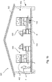
- Figure 1a shows a schematic representation of a livestock shed 500 with an exemplary embodiment of an infrastructure arrangement 1.
- Figure 1b shows a schematic representation of a livestock stable 500 with a further exemplary embodiment of an infrastructure arrangement 1.
- Figure 2 shows a schematic representation of a livestock stable 500 with several livestock residence areas 530.
- Figure 3 shows a schematic representation of a further livestock barn 500 with livestock areas that are arranged on three floors 521, 522, 523 one above the other.
- Figure 4 shows a schematic representation of a top view of a further livestock pen 500 with exemplary configurations of charging stations.
- Figure 5 shows a schematic three-dimensional representation of an exemplary autonomous Stable vehicle 100.
- Figure 6 FIG. 11 shows a schematic representation of the stable vehicle 100 according to FIG Figure 5 with lifted housing and charging station.
- the infrastructure arrangement 1 for a livestock stable 500 comprises a stationary position determination network 400 with several optics-free position determination network points 401, 402, 403, 404.
- the position determination network 400 comprises a plurality of position determination network points, of which only individual position determination network points 401, 402, 403, 404 are representatively shown in the figures are.
- the position determination network points 401 lie on a first horizontal plane and the position determination network points 402 lie on a second horizontal plane.
- the position determination network points 401 are arranged near the stable roof 502, the position determination network points 402 are located below an upper end of the stable fittings 506 and at the same time above a clear height H of the stable fittings 506.
- Position determination network points 402, 403, 404 are preferably provided on each floor 521, 522, 523, which are each arranged above a clear height of the stable installations 506 and below an upper end of the stable installations 506.
- the arrangement of the position determination network points 402 is preferred over an arrangement of position determination network points 401.
- Position determination network points 401 near the stable roof can preferably be dispensed with.
- the optics-free position determination device 410 and the optics-free position determination network 400 have the advantage of reliable position determination in the livestock barn 500, wherein a preferably electronic map of a livestock barn 500 can also be validated and / or corrected and / or improved preferably during operation and / or during commissioning .
- This clear height H preferably corresponds essentially to a height that is slightly greater than the height of the head of livestock located on the stable floor 503, so that they can move under the stable fittings 506.
- the infrastructure arrangement 1 comprises an autonomous stable vehicle 100, which has a drive 132 for driving the crawler track 140 and a charging interface in the form of a loading opening 171.
- the charging opening 171 can be coupled to side walls 162 via the charging pin 163 of the charging base 161 of a charging station 160 in order to charge the drive 132.
- the stable vehicle 100 is further equipped with a coupling device 133 for releasably attaching various functional units, such as a milling machine.
- the stable vehicle 100 has a housing 110 and a base body or chassis 120.
- a position determination device 410 and a control unit 113 are also arranged on the stable vehicle 100.
- the control unit 113 of the autonomous stable vehicle 100 is designed as a function of information from the position determination device 410 and a data transmission unit 420 (cf. Figure 1a ) to generate a schedule for the autonomous stable vehicle 100.
- a user F can have imported information about work orders via a central computer, which information is made available to the stable vehicle 100 via the data transmission unit 420 in order to generate a timetable.
- the work orders can relate, for example, to spreading employment material in an area and to milling out hard litter in an area.
- the schedule can provide a sequence and / or a length of stay in the work areas and / or.
- the user F can enter the work orders, for example, via a man-machine interface and / or via a mobile terminal.
- the schedule of the autonomous stable vehicle 100 could thus look like first driving to a loading station 210 and picking up activity material there.
- the schedule can provide that the autonomous stable vehicle 100 then drives to the area in order to deploy the occupational material there.
- the autonomous stable vehicle 100 can then drive back to the equipping station 210 in accordance with the timetable and to couple with a milling machine as a functional unit. If necessary, it may be preferred to take up additional ballast in a ballast station 220 for the milling.
- the schedule can then provide for the stable vehicle 100 to drive to the area in order to mill hard litter there.
- the schedule can then provide for the autonomous stable vehicle 100 to carry the additional ballast in the Ballast station 220 releases again and / or the milling machine in the equipping station 210 is decoupled again.
- the autonomous stable vehicle can then, for example, take on a recurring task, such as cleaning conveyor belts 350.
- An elongated charging station 360 can preferably be provided in this area so that the stable vehicle can preferably be charged while the conveyor belt 350 is being cleaned.
- An elongated charging station 360 can be designed, for example, for inductive charging or comprise a conductor arranged above the stable vehicle, to which the stable vehicle 100 couples for charging with a charging antenna.
- a charging station 160 can be provided, which is surrounded by an area 230 that is shielded from farm animals, for example in the form of a cattle grille.
- the charging station 160 can also be arranged via a ramp on an elevated plateau in order to compensate for a different height of litter or to be independent of this.
- the charging station 160, the equipping station 210 and the ballasting station 220 can be combined in a stable vehicle supply area 200.
- FIG. 2 To recognize several livestock residence areas 530, which are arranged on one level and in each of which barn fittings 506 are arranged.
- the livestock residence areas 530 are connected via locks 310, which allow the stable vehicle 100 to pass through and prevent livestock from passing through.
- FIG. 3 The example of a livestock barn 500 shown here, the livestock areas are arranged on several levels 521, 522, 523 which are connected via a lift unit 320.
- the stable vehicle 100 can work in all three levels 521, 522, 523 via the lift unit 320.
- the locks 310 and / or the lift unit 320 cleaning devices for cleaning and / or disinfecting the autonomous stable vehicle or parts thereof are preferably provided. Furthermore, the locks 310 and / or the lift unit 320 can also preferably include a charging station for charging the drive of the autonomous stable vehicle and / or a data interface for coupling to the data transmission unit 420.
- the lift unit 320 also preferably comprises an obstacle to the passage of farm animals, so that the farm animals are prevented from changing between floors 521, 522, 523.
- Data interfaces are preferably provided in the locks 310 and / or in the loading stations 160, 360 and / or in the loading station 210 and / or in the ballast station 220, via which the autonomous stable vehicle, in particular its control unit 113, is preferably contact-bound and / or Can communicate wired with the data transmission unit 420, for example, to download new work orders and / or upload collected data.
- the stable vehicle 100 can also follow a user F at a distance in a butler function.
- Objects to be transported can be placed on a storage device 430 of the autonomous stable vehicle 100 and can be transported by the stable vehicle.
Landscapes
- Life Sciences & Earth Sciences (AREA)
- Environmental Sciences (AREA)
- Animal Husbandry (AREA)
- Biodiversity & Conservation Biology (AREA)
- Zoology (AREA)
- Birds (AREA)
- Engineering & Computer Science (AREA)
- Health & Medical Sciences (AREA)
- Transportation (AREA)
- Public Health (AREA)
- Mechanical Engineering (AREA)
- Animal Behavior & Ethology (AREA)
- Physical Education & Sports Medicine (AREA)
- General Health & Medical Sciences (AREA)
- Housing For Livestock And Birds (AREA)
- Management, Administration, Business Operations System, And Electronic Commerce (AREA)
- Catching Or Destruction (AREA)
- Control Of Position, Course, Altitude, Or Attitude Of Moving Bodies (AREA)
Applications Claiming Priority (2)
| Application Number | Priority Date | Filing Date | Title |
|---|---|---|---|
| DE202017103642.1U DE202017103642U1 (de) | 2017-06-20 | 2017-06-20 | Stallfahrzeug |
| PCT/EP2018/066395 WO2018234374A1 (de) | 2017-06-20 | 2018-06-20 | Infrastrukturanordnung für einen nutztierstall und verfahren zur bereitstellung eines solchen |
Publications (2)
| Publication Number | Publication Date |
|---|---|
| EP3638017A1 EP3638017A1 (de) | 2020-04-22 |
| EP3638017B1 true EP3638017B1 (de) | 2020-11-04 |
Family
ID=62750968
Family Applications (2)
| Application Number | Title | Priority Date | Filing Date |
|---|---|---|---|
| EP18734775.2A Active EP3638017B1 (de) | 2017-06-20 | 2018-06-20 | Infrastrukturanordnung für einen nutztierstall und verfahren zur bereitstellung eines solchen |
| EP18734497.3A Active EP3638016B1 (de) | 2017-06-20 | 2018-06-20 | Stallfahrzeug und verfahren |
Family Applications After (1)
| Application Number | Title | Priority Date | Filing Date |
|---|---|---|---|
| EP18734497.3A Active EP3638016B1 (de) | 2017-06-20 | 2018-06-20 | Stallfahrzeug und verfahren |
Country Status (7)
| Country | Link |
|---|---|
| US (2) | US10842130B2 (da) |
| EP (2) | EP3638017B1 (da) |
| CN (2) | CN110785080B (da) |
| DE (1) | DE202017103642U1 (da) |
| DK (1) | DK3638016T3 (da) |
| ES (1) | ES2908811T3 (da) |
| WO (2) | WO2018234379A1 (da) |
Families Citing this family (11)
| Publication number | Priority date | Publication date | Assignee | Title |
|---|---|---|---|---|
| RU2020127711A (ru) * | 2018-02-16 | 2022-03-16 | Делаваль Холдинг Аб | Схема осуществления оборудования для кормления животных |
| EP3598892B1 (de) | 2018-07-25 | 2025-02-19 | Big Dutchman International GmbH | Verfahren zur herstellung einer strohmatte, strohmatte und strohstall |
| NL2021920B1 (en) * | 2018-11-02 | 2020-05-14 | Abraham Vroegindeweij Bastiaan | Egg-collecting device |
| CN109380138A (zh) * | 2018-12-07 | 2019-02-26 | 中国地质大学(武汉) | 一种基于uwb定位的悬挂式投喂机 |
| CN109997730B (zh) * | 2019-04-28 | 2021-08-17 | 山东省农业科学院家禽研究所 | 笼养鸡智能巡检系统及其巡检机器人的巡航控制方法 |
| FR3095923B1 (fr) * | 2019-05-15 | 2021-05-28 | Octopus Robots | Ensemble mobile autonome pour traiter une litière d’un enclos comprenant un dispositif d’éloignement d’animaux |
| NL2023390B1 (en) * | 2019-06-26 | 2021-02-01 | Lely Patent Nv | Method of feeding a group of animals at a feeding location and system for performing the method |
| KR102756881B1 (ko) * | 2019-07-23 | 2025-01-21 | 엘지전자 주식회사 | 차랑에 탑재되어 자가진단을 수행하는 인공 지능 장치 및 그 방법 |
| CN111567425A (zh) * | 2020-05-06 | 2020-08-25 | 上海一芃机器人科技有限公司 | 一种草食动物日粮搅拌饲喂机器人 |
| AT523886A1 (de) * | 2020-06-03 | 2021-12-15 | Wasserbauer Holding Gmbh | Anordnung zur Steuerung eines selbstfahrenden Arbeitsgeräts |
| DE102021131077A1 (de) * | 2021-11-26 | 2023-06-01 | Gea Farm Technologies Gmbh | Fahrroboter für landwirtschaftliche Aufgaben |
Family Cites Families (29)
| Publication number | Priority date | Publication date | Assignee | Title |
|---|---|---|---|---|
| US6338013B1 (en) * | 1999-03-19 | 2002-01-08 | Bryan John Ruffner | Multifunctional mobile appliance |
| NL1012138C2 (nl) * | 1999-05-25 | 2000-11-28 | Lely Res Holding | Klimaatkar. |
| AR028632A1 (es) * | 2000-05-16 | 2003-05-21 | Hildo Ortiz | Dispositivo para recolectar excrementos de animales en la via publica |
| JP2003153639A (ja) * | 2001-11-19 | 2003-05-27 | Kao Corp | ペット用トイレ |
| US20050217589A1 (en) * | 2004-04-02 | 2005-10-06 | Daniel Brace B | Agitation of poultry by applied robotics |
| US7549396B2 (en) * | 2006-02-07 | 2009-06-23 | I Did It, Inc. | Breakable active odor control additive for animal litter |
| NL1030091C2 (nl) * | 2005-10-03 | 2007-04-04 | Maasland Nv | Inrichting voor het verplaatsen van voorwerpen, samenstel van een dergelijke inrichting en een stal. |
| DE202007003455U1 (de) * | 2007-03-06 | 2007-05-16 | Big Dutchman International Gmbh | Käfiganordnung für Geflügel, vorzugsweise für Masthähnchen (Broiler) |
| NL1033590C2 (nl) * | 2007-03-26 | 2008-09-29 | Maasland Nv | Onbemand voertuig voor het afgeven van voer aan een dier. |
| ITFI20070116A1 (it) * | 2007-05-17 | 2008-11-18 | Fabrizio Bernini | Tagliaerba |
| ITBO20080040A1 (it) * | 2008-01-23 | 2009-07-24 | Fabrizio Bernini | Tagliaerba. |
| NL1035980C (nl) * | 2008-09-25 | 2010-03-26 | Lely Patent Nv | Onbemand voertuig voor het verplaatsen van mest. |
| CN101401551B (zh) * | 2008-11-13 | 2012-10-31 | 杨兆生 | 鸡舍清扫车 |
| CN101946716B (zh) * | 2010-09-08 | 2014-03-26 | 中国环境科学研究院 | 分散式环保型猪舍 |
| CN102138535B (zh) * | 2011-01-30 | 2012-09-12 | 殷逢宝 | 一种具有自动清理粪便装置的母猪产床 |
| NL2008671C2 (nl) * | 2012-04-20 | 2013-10-23 | Lely Patent Nv | Voersysteem en werkwijze voor het voeren van dieren. |
| CN203279630U (zh) * | 2012-09-05 | 2013-11-13 | 吉林农业大学 | 架空猪床结构的猪舍 |
| DE102012017966A1 (de) * | 2012-09-12 | 2014-03-13 | Big Dutchman International Gmbh | Verfahren und System zum Überwachen und/oder Steuern des Ressourcenverbrauchs einer landwirtschaftlichen Anlage |
| CN103141432A (zh) * | 2013-03-07 | 2013-06-12 | 冯嘉昕 | 一种无臭零排放健康畜禽养殖方法及设备 |
| EP3041346A2 (en) * | 2013-09-05 | 2016-07-13 | DeLaval Holding AB | Scraper device, scraping arrangement and guide rail |
| US20150250137A1 (en) | 2013-11-27 | 2015-09-10 | Dansk Mink Papir A/S | Motorized feeding vehicle and a method of operating an animal farming system |
| JP5655132B1 (ja) * | 2013-12-27 | 2015-01-14 | ユニ・チャーム株式会社 | 吸収性部材のカバー部材及びこれを用いたペット用トイレ |
| CA2885877A1 (en) * | 2014-03-25 | 2015-09-25 | Dansk Mink Papir A/S | A motorized feeding vehicle and a method of operating an animal farming system |
| GB2534265B (en) * | 2014-08-11 | 2020-10-07 | James Webber Simon | Animal excrement collection |
| DE102014116882B4 (de) * | 2014-11-18 | 2018-05-24 | B. Strautmann & Söhne GmbH u. Co. KG | Verfahren zur Entnahme von Futtermitteln aus Fahrsilos |
| NL2014187B1 (nl) * | 2015-01-26 | 2017-01-06 | Lely Patent Nv | Landbouwkundig managamentsysteem. |
| DE202015101803U1 (de) * | 2015-04-13 | 2015-05-04 | Big Dutchman International Gmbh | Geflügelhalteeinrichtung mit zusätzlichen Sitzstangen |
| NL2014622B1 (en) * | 2015-04-13 | 2017-01-20 | Lely Patent Nv | System and method to carry out a first stable floor related action. |
| FR3044868B1 (fr) * | 2015-12-15 | 2018-10-12 | Tibot | Robot mobile d’education pour elevage avicole et installation d'elevage mettant en oeuvre un ou plusieurs robots |
-
2017
- 2017-06-20 DE DE202017103642.1U patent/DE202017103642U1/de active Active
-
2018
- 2018-06-20 US US16/624,558 patent/US10842130B2/en active Active
- 2018-06-20 EP EP18734775.2A patent/EP3638017B1/de active Active
- 2018-06-20 EP EP18734497.3A patent/EP3638016B1/de active Active
- 2018-06-20 CN CN201880041681.2A patent/CN110785080B/zh active Active
- 2018-06-20 DK DK18734497.3T patent/DK3638016T3/da active
- 2018-06-20 US US16/624,416 patent/US20200229395A1/en not_active Abandoned
- 2018-06-20 CN CN201880041539.8A patent/CN110868849B/zh active Active
- 2018-06-20 ES ES18734497T patent/ES2908811T3/es active Active
- 2018-06-20 WO PCT/EP2018/066411 patent/WO2018234379A1/de not_active Ceased
- 2018-06-20 WO PCT/EP2018/066395 patent/WO2018234374A1/de not_active Ceased
Non-Patent Citations (1)
| Title |
|---|
| None * |
Also Published As
| Publication number | Publication date |
|---|---|
| WO2018234379A1 (de) | 2018-12-27 |
| ES2908811T3 (es) | 2022-05-04 |
| EP3638016B1 (de) | 2021-12-15 |
| US10842130B2 (en) | 2020-11-24 |
| EP3638016A1 (de) | 2020-04-22 |
| EP3638017A1 (de) | 2020-04-22 |
| CN110785080A (zh) | 2020-02-11 |
| WO2018234374A1 (de) | 2018-12-27 |
| US20200214263A1 (en) | 2020-07-09 |
| DK3638016T3 (da) | 2022-01-10 |
| CN110868849B (zh) | 2021-06-04 |
| CN110868849A (zh) | 2020-03-06 |
| DE202017103642U1 (de) | 2018-09-24 |
| CN110785080B (zh) | 2022-06-03 |
| US20200229395A1 (en) | 2020-07-23 |
Similar Documents
| Publication | Publication Date | Title |
|---|---|---|
| EP3638017B1 (de) | Infrastrukturanordnung für einen nutztierstall und verfahren zur bereitstellung eines solchen | |
| EP3703902B1 (de) | Fördersystem und verfahren zum gleichzeitigen transport von werkstücken und werkern | |
| EP3412133B1 (de) | Bodenbearbeitungssystem mit mindestens einer ladestation | |
| DE102011000820B4 (de) | Frachtladesystem und Verfahren zur Steuerung einer Vielzahl von Frachtfördereinrichtungen | |
| DE69525931T2 (de) | Futterwagen | |
| EP2786325B1 (de) | Verfahren und vorrichtung zum koordinieren einer transportlogistik sowie transportlogistiksystem | |
| DE10196988T5 (de) | Robotersystem | |
| DE202020006143U1 (de) | Sortiersystem | |
| WO2016078757A1 (de) | Autonomes fahrzeug, insbesondere futtermischwagen, und verfahren zur steuerung eines autonomen fahrzeugs | |
| DE10196992T5 (de) | Robotersystem | |
| WO2011035839A2 (de) | System von mobilen robotern mit einer basisstation | |
| DE202020103181U1 (de) | Ein autonomer Gabelstapler | |
| EP4169365A1 (de) | Technik zum automatisierten bepflanzen eines geländes | |
| DE102017104933B3 (de) | Autonome selbstbewegende Arbeitsmaschine sowie autonomes selbstbewegendes Arbeitsmaschinensystem | |
| EP4342080A1 (de) | Reinigungsvorrichtung zum automatischen reinigen von solarmodulen einer solar-anlage | |
| DE102014113909A1 (de) | Selbstfahrende Arbeitsmaschine | |
| DE102014215293A1 (de) | Kraftfahrzeug für den Transport eines Tieres, Verfahren zur Erleichterung eines Zugangs zu einer Zugangsöffnung eines Kraftfahrzeugs und fahrzeugexterner Transmitter für ein Tier oder Tierhalsband | |
| DE102010001709A1 (de) | Ladesystem und Verfahren zum Laden von Elektrofahrzeugen | |
| DE102005012561B4 (de) | Verfahren zum Betrieb eines Werkstück-Transfersystems | |
| DE202024104110U1 (de) | Autonome Arbeitsvorrichtung und zugehöriges System | |
| EP4544366A1 (de) | Verfahren und system zum anlernen einer fahrstrecke eines autonom fahrenden landwirtschaftlichen fahrroboters | |
| EP4065453B1 (de) | Fördervorrichtung, bearbeitungsanlage, verfahren zum fördern und/oder bearbeiten von gegenständen | |
| EP2260692A1 (de) | System und Vorrichtung zur Automatisierung der Ernte in Baumkulturen | |
| EP3851929A1 (de) | Verfahren zum betrieb eines systems mit mindestens zwei sich selbsttätig fortbewegenden bodenbearbeitungsgeräten sowie system zur durchführung eines solchen verfahrens | |
| DE102020003118A1 (de) | System zum Einsammeln von Gegenständen und/oder zur Bearbeitung einer Verfahrfläche und Verfahren zum Betreiben eines Systems |
Legal Events
| Date | Code | Title | Description |
|---|---|---|---|
| STAA | Information on the status of an ep patent application or granted ep patent |
Free format text: STATUS: UNKNOWN |
|
| STAA | Information on the status of an ep patent application or granted ep patent |
Free format text: STATUS: THE INTERNATIONAL PUBLICATION HAS BEEN MADE |
|
| PUAI | Public reference made under article 153(3) epc to a published international application that has entered the european phase |
Free format text: ORIGINAL CODE: 0009012 |
|
| STAA | Information on the status of an ep patent application or granted ep patent |
Free format text: STATUS: REQUEST FOR EXAMINATION WAS MADE |
|
| 17P | Request for examination filed |
Effective date: 20200117 |
|
| AK | Designated contracting states |
Kind code of ref document: A1 Designated state(s): AL AT BE BG CH CY CZ DE DK EE ES FI FR GB GR HR HU IE IS IT LI LT LU LV MC MK MT NL NO PL PT RO RS SE SI SK SM TR |
|
| AX | Request for extension of the european patent |
Extension state: BA ME |
|
| GRAP | Despatch of communication of intention to grant a patent |
Free format text: ORIGINAL CODE: EPIDOSNIGR1 |
|
| STAA | Information on the status of an ep patent application or granted ep patent |
Free format text: STATUS: GRANT OF PATENT IS INTENDED |
|
| RIC1 | Information provided on ipc code assigned before grant |
Ipc: A01K 15/02 20060101ALI20200511BHEP Ipc: A01K 29/00 20060101ALI20200511BHEP Ipc: A01K 31/04 20060101ALI20200511BHEP Ipc: A01K 45/00 20060101ALI20200511BHEP Ipc: A01K 15/00 20060101ALI20200511BHEP Ipc: A01K 1/00 20060101ALI20200511BHEP Ipc: A01K 1/015 20060101AFI20200511BHEP |
|
| DAV | Request for validation of the european patent (deleted) | ||
| DAX | Request for extension of the european patent (deleted) | ||
| INTG | Intention to grant announced |
Effective date: 20200608 |
|
| GRAS | Grant fee paid |
Free format text: ORIGINAL CODE: EPIDOSNIGR3 |
|
| GRAA | (expected) grant |
Free format text: ORIGINAL CODE: 0009210 |
|
| STAA | Information on the status of an ep patent application or granted ep patent |
Free format text: STATUS: THE PATENT HAS BEEN GRANTED |
|
| AK | Designated contracting states |
Kind code of ref document: B1 Designated state(s): AL AT BE BG CH CY CZ DE DK EE ES FI FR GB GR HR HU IE IS IT LI LT LU LV MC MK MT NL NO PL PT RO RS SE SI SK SM TR |
|
| REG | Reference to a national code |
Ref country code: GB Ref legal event code: FG4D Free format text: NOT ENGLISH |
|
| REG | Reference to a national code |
Ref country code: CH Ref legal event code: EP |
|
| REG | Reference to a national code |
Ref country code: AT Ref legal event code: REF Ref document number: 1329623 Country of ref document: AT Kind code of ref document: T Effective date: 20201115 |
|
| REG | Reference to a national code |
Ref country code: DE Ref legal event code: R096 Ref document number: 502018002937 Country of ref document: DE |
|
| REG | Reference to a national code |
Ref country code: IE Ref legal event code: FG4D Free format text: LANGUAGE OF EP DOCUMENT: GERMAN |
|
| REG | Reference to a national code |
Ref country code: NL Ref legal event code: FP |
|
| PG25 | Lapsed in a contracting state [announced via postgrant information from national office to epo] |
Ref country code: FI Free format text: LAPSE BECAUSE OF FAILURE TO SUBMIT A TRANSLATION OF THE DESCRIPTION OR TO PAY THE FEE WITHIN THE PRESCRIBED TIME-LIMIT Effective date: 20201104 Ref country code: PT Free format text: LAPSE BECAUSE OF FAILURE TO SUBMIT A TRANSLATION OF THE DESCRIPTION OR TO PAY THE FEE WITHIN THE PRESCRIBED TIME-LIMIT Effective date: 20210304 Ref country code: RS Free format text: LAPSE BECAUSE OF FAILURE TO SUBMIT A TRANSLATION OF THE DESCRIPTION OR TO PAY THE FEE WITHIN THE PRESCRIBED TIME-LIMIT Effective date: 20201104 Ref country code: GR Free format text: LAPSE BECAUSE OF FAILURE TO SUBMIT A TRANSLATION OF THE DESCRIPTION OR TO PAY THE FEE WITHIN THE PRESCRIBED TIME-LIMIT Effective date: 20210205 Ref country code: NO Free format text: LAPSE BECAUSE OF FAILURE TO SUBMIT A TRANSLATION OF THE DESCRIPTION OR TO PAY THE FEE WITHIN THE PRESCRIBED TIME-LIMIT Effective date: 20210204 |
|
| PG25 | Lapsed in a contracting state [announced via postgrant information from national office to epo] |
Ref country code: BG Free format text: LAPSE BECAUSE OF FAILURE TO SUBMIT A TRANSLATION OF THE DESCRIPTION OR TO PAY THE FEE WITHIN THE PRESCRIBED TIME-LIMIT Effective date: 20210204 Ref country code: SE Free format text: LAPSE BECAUSE OF FAILURE TO SUBMIT A TRANSLATION OF THE DESCRIPTION OR TO PAY THE FEE WITHIN THE PRESCRIBED TIME-LIMIT Effective date: 20201104 Ref country code: PL Free format text: LAPSE BECAUSE OF FAILURE TO SUBMIT A TRANSLATION OF THE DESCRIPTION OR TO PAY THE FEE WITHIN THE PRESCRIBED TIME-LIMIT Effective date: 20201104 Ref country code: IS Free format text: LAPSE BECAUSE OF FAILURE TO SUBMIT A TRANSLATION OF THE DESCRIPTION OR TO PAY THE FEE WITHIN THE PRESCRIBED TIME-LIMIT Effective date: 20210304 Ref country code: LV Free format text: LAPSE BECAUSE OF FAILURE TO SUBMIT A TRANSLATION OF THE DESCRIPTION OR TO PAY THE FEE WITHIN THE PRESCRIBED TIME-LIMIT Effective date: 20201104 Ref country code: ES Free format text: LAPSE BECAUSE OF FAILURE TO SUBMIT A TRANSLATION OF THE DESCRIPTION OR TO PAY THE FEE WITHIN THE PRESCRIBED TIME-LIMIT Effective date: 20201104 |
|
| REG | Reference to a national code |
Ref country code: LT Ref legal event code: MG9D |
|
| PG25 | Lapsed in a contracting state [announced via postgrant information from national office to epo] |
Ref country code: HR Free format text: LAPSE BECAUSE OF FAILURE TO SUBMIT A TRANSLATION OF THE DESCRIPTION OR TO PAY THE FEE WITHIN THE PRESCRIBED TIME-LIMIT Effective date: 20201104 |
|
| PG25 | Lapsed in a contracting state [announced via postgrant information from national office to epo] |
Ref country code: SM Free format text: LAPSE BECAUSE OF FAILURE TO SUBMIT A TRANSLATION OF THE DESCRIPTION OR TO PAY THE FEE WITHIN THE PRESCRIBED TIME-LIMIT Effective date: 20201104 Ref country code: SK Free format text: LAPSE BECAUSE OF FAILURE TO SUBMIT A TRANSLATION OF THE DESCRIPTION OR TO PAY THE FEE WITHIN THE PRESCRIBED TIME-LIMIT Effective date: 20201104 Ref country code: EE Free format text: LAPSE BECAUSE OF FAILURE TO SUBMIT A TRANSLATION OF THE DESCRIPTION OR TO PAY THE FEE WITHIN THE PRESCRIBED TIME-LIMIT Effective date: 20201104 Ref country code: CZ Free format text: LAPSE BECAUSE OF FAILURE TO SUBMIT A TRANSLATION OF THE DESCRIPTION OR TO PAY THE FEE WITHIN THE PRESCRIBED TIME-LIMIT Effective date: 20201104 Ref country code: RO Free format text: LAPSE BECAUSE OF FAILURE TO SUBMIT A TRANSLATION OF THE DESCRIPTION OR TO PAY THE FEE WITHIN THE PRESCRIBED TIME-LIMIT Effective date: 20201104 Ref country code: LT Free format text: LAPSE BECAUSE OF FAILURE TO SUBMIT A TRANSLATION OF THE DESCRIPTION OR TO PAY THE FEE WITHIN THE PRESCRIBED TIME-LIMIT Effective date: 20201104 |
|
| REG | Reference to a national code |
Ref country code: DE Ref legal event code: R097 Ref document number: 502018002937 Country of ref document: DE |
|
| PG25 | Lapsed in a contracting state [announced via postgrant information from national office to epo] |
Ref country code: DK Free format text: LAPSE BECAUSE OF FAILURE TO SUBMIT A TRANSLATION OF THE DESCRIPTION OR TO PAY THE FEE WITHIN THE PRESCRIBED TIME-LIMIT Effective date: 20201104 |
|
| PLBE | No opposition filed within time limit |
Free format text: ORIGINAL CODE: 0009261 |
|
| STAA | Information on the status of an ep patent application or granted ep patent |
Free format text: STATUS: NO OPPOSITION FILED WITHIN TIME LIMIT |
|
| 26N | No opposition filed |
Effective date: 20210805 |
|
| PG25 | Lapsed in a contracting state [announced via postgrant information from national office to epo] |
Ref country code: AL Free format text: LAPSE BECAUSE OF FAILURE TO SUBMIT A TRANSLATION OF THE DESCRIPTION OR TO PAY THE FEE WITHIN THE PRESCRIBED TIME-LIMIT Effective date: 20201104 Ref country code: IT Free format text: LAPSE BECAUSE OF FAILURE TO SUBMIT A TRANSLATION OF THE DESCRIPTION OR TO PAY THE FEE WITHIN THE PRESCRIBED TIME-LIMIT Effective date: 20201104 |
|
| PG25 | Lapsed in a contracting state [announced via postgrant information from national office to epo] |
Ref country code: SI Free format text: LAPSE BECAUSE OF FAILURE TO SUBMIT A TRANSLATION OF THE DESCRIPTION OR TO PAY THE FEE WITHIN THE PRESCRIBED TIME-LIMIT Effective date: 20201104 |
|
| PG25 | Lapsed in a contracting state [announced via postgrant information from national office to epo] |
Ref country code: MC Free format text: LAPSE BECAUSE OF FAILURE TO SUBMIT A TRANSLATION OF THE DESCRIPTION OR TO PAY THE FEE WITHIN THE PRESCRIBED TIME-LIMIT Effective date: 20201104 |
|
| REG | Reference to a national code |
Ref country code: CH Ref legal event code: PL |
|
| REG | Reference to a national code |
Ref country code: BE Ref legal event code: MM Effective date: 20210630 |
|
| PG25 | Lapsed in a contracting state [announced via postgrant information from national office to epo] |
Ref country code: LU Free format text: LAPSE BECAUSE OF NON-PAYMENT OF DUE FEES Effective date: 20210620 |
|
| PG25 | Lapsed in a contracting state [announced via postgrant information from national office to epo] |
Ref country code: LI Free format text: LAPSE BECAUSE OF NON-PAYMENT OF DUE FEES Effective date: 20210630 Ref country code: IE Free format text: LAPSE BECAUSE OF NON-PAYMENT OF DUE FEES Effective date: 20210620 Ref country code: CH Free format text: LAPSE BECAUSE OF NON-PAYMENT OF DUE FEES Effective date: 20210630 |
|
| PG25 | Lapsed in a contracting state [announced via postgrant information from national office to epo] |
Ref country code: IS Free format text: LAPSE BECAUSE OF FAILURE TO SUBMIT A TRANSLATION OF THE DESCRIPTION OR TO PAY THE FEE WITHIN THE PRESCRIBED TIME-LIMIT Effective date: 20210304 |
|
| PG25 | Lapsed in a contracting state [announced via postgrant information from national office to epo] |
Ref country code: BE Free format text: LAPSE BECAUSE OF NON-PAYMENT OF DUE FEES Effective date: 20210630 |
|
| P01 | Opt-out of the competence of the unified patent court (upc) registered |
Effective date: 20230523 |
|
| PG25 | Lapsed in a contracting state [announced via postgrant information from national office to epo] |
Ref country code: CY Free format text: LAPSE BECAUSE OF FAILURE TO SUBMIT A TRANSLATION OF THE DESCRIPTION OR TO PAY THE FEE WITHIN THE PRESCRIBED TIME-LIMIT Effective date: 20201104 |
|
| PG25 | Lapsed in a contracting state [announced via postgrant information from national office to epo] |
Ref country code: HU Free format text: LAPSE BECAUSE OF FAILURE TO SUBMIT A TRANSLATION OF THE DESCRIPTION OR TO PAY THE FEE WITHIN THE PRESCRIBED TIME-LIMIT; INVALID AB INITIO Effective date: 20180620 |
|
| PG25 | Lapsed in a contracting state [announced via postgrant information from national office to epo] |
Ref country code: MK Free format text: LAPSE BECAUSE OF FAILURE TO SUBMIT A TRANSLATION OF THE DESCRIPTION OR TO PAY THE FEE WITHIN THE PRESCRIBED TIME-LIMIT Effective date: 20201104 |
|
| REG | Reference to a national code |
Ref country code: AT Ref legal event code: MM01 Ref document number: 1329623 Country of ref document: AT Kind code of ref document: T Effective date: 20230620 |
|
| PG25 | Lapsed in a contracting state [announced via postgrant information from national office to epo] |
Ref country code: MT Free format text: LAPSE BECAUSE OF FAILURE TO SUBMIT A TRANSLATION OF THE DESCRIPTION OR TO PAY THE FEE WITHIN THE PRESCRIBED TIME-LIMIT Effective date: 20201104 |
|
| PG25 | Lapsed in a contracting state [announced via postgrant information from national office to epo] |
Ref country code: AT Free format text: LAPSE BECAUSE OF NON-PAYMENT OF DUE FEES Effective date: 20230620 |
|
| PG25 | Lapsed in a contracting state [announced via postgrant information from national office to epo] |
Ref country code: AT Free format text: LAPSE BECAUSE OF NON-PAYMENT OF DUE FEES Effective date: 20230620 |
|
| PGFP | Annual fee paid to national office [announced via postgrant information from national office to epo] |
Ref country code: GB Payment date: 20250620 Year of fee payment: 8 |
|
| PGFP | Annual fee paid to national office [announced via postgrant information from national office to epo] |
Ref country code: NL Payment date: 20250618 Year of fee payment: 8 |
|
| PGFP | Annual fee paid to national office [announced via postgrant information from national office to epo] |
Ref country code: FR Payment date: 20250618 Year of fee payment: 8 |
|
| PGFP | Annual fee paid to national office [announced via postgrant information from national office to epo] |
Ref country code: DE Payment date: 20250701 Year of fee payment: 8 |
|
| PG25 | Lapsed in a contracting state [announced via postgrant information from national office to epo] |
Ref country code: TR Free format text: LAPSE BECAUSE OF FAILURE TO SUBMIT A TRANSLATION OF THE DESCRIPTION OR TO PAY THE FEE WITHIN THE PRESCRIBED TIME-LIMIT Effective date: 20201104 |
|
| PGFP | Annual fee paid to national office [announced via postgrant information from national office to epo] |
Ref country code: AT Payment date: 20260410 Year of fee payment: 5 |