EP3636365A1 - Casting mould for manufaturing a casting part by having at least one internal contour - Google Patents
Casting mould for manufaturing a casting part by having at least one internal contour Download PDFInfo
- Publication number
- EP3636365A1 EP3636365A1 EP19200013.1A EP19200013A EP3636365A1 EP 3636365 A1 EP3636365 A1 EP 3636365A1 EP 19200013 A EP19200013 A EP 19200013A EP 3636365 A1 EP3636365 A1 EP 3636365A1
- Authority
- EP
- European Patent Office
- Prior art keywords
- mandrel
- core
- casting
- core segments
- casting mold
- Prior art date
- Legal status (The legal status is an assumption and is not a legal conclusion. Google has not performed a legal analysis and makes no representation as to the accuracy of the status listed.)
- Granted
Links
- 238000005266 casting Methods 0.000 title claims abstract description 51
- 238000003384 imaging method Methods 0.000 claims abstract description 3
- 230000007246 mechanism Effects 0.000 claims description 5
- 230000000295 complement effect Effects 0.000 claims description 4
- 238000013461 design Methods 0.000 claims description 3
- 230000015572 biosynthetic process Effects 0.000 claims 1
- 238000004512 die casting Methods 0.000 description 5
- 238000003754 machining Methods 0.000 description 3
- 230000001419 dependent effect Effects 0.000 description 2
- 238000004519 manufacturing process Methods 0.000 description 2
- 239000000463 material Substances 0.000 description 2
- 238000005058 metal casting Methods 0.000 description 2
- FYYHWMGAXLPEAU-UHFFFAOYSA-N Magnesium Chemical compound [Mg] FYYHWMGAXLPEAU-UHFFFAOYSA-N 0.000 description 1
- 229910045601 alloy Inorganic materials 0.000 description 1
- 239000000956 alloy Substances 0.000 description 1
- 229910052782 aluminium Inorganic materials 0.000 description 1
- XAGFODPZIPBFFR-UHFFFAOYSA-N aluminium Chemical compound [Al] XAGFODPZIPBFFR-UHFFFAOYSA-N 0.000 description 1
- 230000005540 biological transmission Effects 0.000 description 1
- 230000006835 compression Effects 0.000 description 1
- 238000007906 compression Methods 0.000 description 1
- 238000010276 construction Methods 0.000 description 1
- 238000011161 development Methods 0.000 description 1
- 230000018109 developmental process Effects 0.000 description 1
- 238000006073 displacement reaction Methods 0.000 description 1
- 210000003746 feather Anatomy 0.000 description 1
- 238000003475 lamination Methods 0.000 description 1
- 229910001338 liquidmetal Inorganic materials 0.000 description 1
- 229910052749 magnesium Inorganic materials 0.000 description 1
- 239000011777 magnesium Substances 0.000 description 1
- 238000005259 measurement Methods 0.000 description 1
- 239000000155 melt Substances 0.000 description 1
- 229910052751 metal Inorganic materials 0.000 description 1
- 239000002184 metal Substances 0.000 description 1
- 150000002739 metals Chemical class 0.000 description 1
- 238000000034 method Methods 0.000 description 1
- 230000002093 peripheral effect Effects 0.000 description 1
- 238000012805 post-processing Methods 0.000 description 1
- 238000007493 shaping process Methods 0.000 description 1
- 238000007711 solidification Methods 0.000 description 1
- 230000008023 solidification Effects 0.000 description 1
Images

Classifications
-
- B—PERFORMING OPERATIONS; TRANSPORTING
- B22—CASTING; POWDER METALLURGY
- B22C—FOUNDRY MOULDING
- B22C9/00—Moulds or cores; Moulding processes
- B22C9/06—Permanent moulds for shaped castings
-
- B—PERFORMING OPERATIONS; TRANSPORTING
- B22—CASTING; POWDER METALLURGY
- B22C—FOUNDRY MOULDING
- B22C9/00—Moulds or cores; Moulding processes
- B22C9/06—Permanent moulds for shaped castings
- B22C9/064—Locating means for cores
-
- B—PERFORMING OPERATIONS; TRANSPORTING
- B22—CASTING; POWDER METALLURGY
- B22C—FOUNDRY MOULDING
- B22C9/00—Moulds or cores; Moulding processes
- B22C9/22—Moulds for peculiarly-shaped castings
-
- B—PERFORMING OPERATIONS; TRANSPORTING
- B22—CASTING; POWDER METALLURGY
- B22D—CASTING OF METALS; CASTING OF OTHER SUBSTANCES BY THE SAME PROCESSES OR DEVICES
- B22D17/00—Pressure die casting or injection die casting, i.e. casting in which the metal is forced into a mould under high pressure
- B22D17/20—Accessories: Details
- B22D17/22—Dies; Die plates; Die supports; Cooling equipment for dies; Accessories for loosening and ejecting castings from dies
- B22D17/229—Dies; Die plates; Die supports; Cooling equipment for dies; Accessories for loosening and ejecting castings from dies with exchangeable die part
-
- B—PERFORMING OPERATIONS; TRANSPORTING
- B22—CASTING; POWDER METALLURGY
- B22D—CASTING OF METALS; CASTING OF OTHER SUBSTANCES BY THE SAME PROCESSES OR DEVICES
- B22D17/00—Pressure die casting or injection die casting, i.e. casting in which the metal is forced into a mould under high pressure
- B22D17/20—Accessories: Details
- B22D17/22—Dies; Die plates; Die supports; Cooling equipment for dies; Accessories for loosening and ejecting castings from dies
- B22D17/24—Accessories for locating and holding cores or inserts
Definitions
- the invention relates to a casting mold or a casting tool for producing a (metallic) casting, which has at least one inner contour.
- a casting mold is a mostly metallic (reusable) permanent mold for the production of cast (building) parts.
- a casting mold has a mold cavity which can be filled with melt or liquid metal and which depicts the casting. Hollow or inner contours provided in the casting can be mapped using immobile cores or movable sliders.
- a casting mold is constructed in several parts and consists, for. B. from a fixed and a movable mold half. So-called draft angles are also required in order to be able to lift the cast part. Such chamfers are also to be provided on cores (insofar as they are reusable permanent cores) or on slides. Drafts lead to oversizes on the casting.
- the casting mold (casting tool) according to the invention is, in particular, a mold for mold casting or a die-casting or die-casting mold for the pressure casting of metals, in particular light metals.
- the invention is also suitable for other metal casting processes in which permanent molds are used.
- Both the mandrel and the core segments are part of the casting mold and form a permanent core.
- the mandrel can be moved in its longitudinal or axial direction and can be extended and retracted using a suitable drive, which is comparatively easy to do.
- a suitable drive which is comparatively easy to do.
- the mandrel When the mandrel is extended, it is moved or pushed forward in the direction of the mold cavity.
- the mandrel When the mandrel is retracted, it is moved or retracted in the opposite direction (i.e. out of the mold cavity).
- the core segments are moved outward, in particular substantially perpendicular, to the direction of movement of the mandrel and assume a pouring position or pouring position.
- the core is quasi widened and takes on the shape of the inner contour to be imaged.
- the core segments When the mandrel is retracted, the core segments are moved inwards transversely to the direction of movement of the mandrel and assume a demolding position or demolding position, the core being quasi reduced or narrowed in cross section and demolding of the cast part produced being possible without shaping bevel or draft bevel.
- the inner contour only small machining allowances are required, which on the one hand reduces the amount of reworking and reduces the material consumption and on the other hand reduces the risk of missing parts.
- the mandrel is preferably arranged centrally and the core segments are arranged around the mandrel. This enables a compact core structure and ensures an effective function.
- the mandrel and the core segments can be formed with complementary inclined surfaces that form a wedge slide mechanism.
- Wedge slide mechanisms are known in various designs from tool making.
- the mandrel can, for example, have a conical or frustoconical section on which the core segments formed with corresponding complementary surfaces can slide and are thereby displaced transversely to the direction of movement of the mandrel.
- the core segments can be biased against the mandrel by means of springs.
- the springs which are in particular compression springs (spiral springs), ensure contact between the core segments and the mandrel and can also cause the core segments to be returned (to the demolding position).
- the reset can also be done hydraulically, pneumatically or mechanically (e.g. using an umbrella mechanism or another suitable joint system).
- the core segments are preferably motion-guided by means of groove guides or the like.
- the core segments can, for example, be mounted in grooves provided for this purpose by means of one or more sliding blocks.
- the groove guides can also be formed with end stops that limit the movements of the core segments.
- the core segments can have shaped elements that enable the depiction of an undercut inner contour. This means that undercuts can already be made on the inner contour of the casting during casting, which would no longer be demouldable with conventional permanent cores or slides.
- the cast part to be produced has a hollow cylindrical region, the (cylindrical) inner contour of which is imaged with a multi-part core (according to the invention), this core having three (or more) movable core segments and the mandrel with three (or more) Pockets is formed in which these core segments are arranged (transversely movable).
- the mandrel preferably has three (or more) radially extending webs or radial webs which extend (in the longitudinal and radial directions) between the pockets, the (radial) outer surfaces of these radial webs together with the (radial) outer surfaces of the in Core segments located in the casting position specify or define the inner contour to be imaged.
- the (radial) outer surfaces of the radial webs are preferably designed with bevels so that the mandrel can be retracted or withdrawn more easily.
- the casting mold according to the invention is preferably used to produce a stator pot for an electric machine, for which purpose an aluminum or magnesium casting alloy is used in particular. Nevertheless, the invention is not limited to this.
- the die 100 shown has a lower, fixed mold half 110 and an upper, movable mold half 120.
- the lower mold half 110 is formed with a mold cavity 130 for producing a ring-cylindrical die casting (construction) part 200.
- the hollow cylindrical inner contour is imaged with the aid of a core 140 which will be explained in more detail below and which is intended to keep the cavity free of melt during die casting. That is, the mold cavity 130 is formed by an outer cavity wall of the lower mold half 110 and an inner cavity wall of the core 140, which together with the end cavity walls define the shape or shape of the die-cast part 200 to be produced.
- the standing orientation is only an example.
- the mold halves 110, 120 can also be designed with a vertical division as right and left mold halves.
- the die-cast part 200 is e.g. B. a thin-walled stator pot for receiving stator laminations in an electric machine for the traction drive (electric drive) of a motor vehicle.
- the die-cast part 200 is comparatively thin-walled in terms of its diameter (for example> 200 mm) (for example ⁇ 5 mm).
- high demands are placed on the die-cast part 200.
- the draft angles usually to be provided on the outer cavity wall and on the inner cavity wall are dependent from the helix angle to high and uneven wall thicknesses, which increases the risk of missing parts.
- the core 140 is formed in several parts and has a plurality of transversely movable core segments 146 and a mandrel 141 arranged longitudinally or axially displaceably between these core segments 146.
- the mandrel 141 is like out Fig. 2 and Fig. 4 can be seen, formed with three uniform pockets 145, in which the identically shaped core segments 146 are arranged.
- the mandrel 141 is also formed with a central cone or truncated cone 142 and three radial webs 143 projecting therefrom in the radial direction R, which extend wing-like at an angular distance of approximately 120 ° between the pockets 145.
- the mandrel 141 is preferably manufactured in one piece, as in FIG Fig. 4 shown.
- the core segments 146 bear on their radial inner surfaces in a form-fitting manner on the cone 142 and for this purpose are designed with complementary partial conical surfaces.
- the core segments 146 When extending the mandrel 141, for which purpose as in Fig. 1 illustrated is moved upwards, the core segments 146 are moved radially outwards by means of a wedge slide mechanism (the cone 142 acts like a driving wedge) transversely to the direction of movement of the mandrel 141 (the displacement path and a transmission ratio can be set via the inclination of the sloping surfaces sliding against one another) a casting position, wherein the radial outer surfaces 144 of the radial webs 143 together with the radial outer surfaces 147 of the core segments 146 define the cylindrical inner contour to be imaged. Furthermore, the core segments 146 have shaped elements 148 on their outer surfaces 147 (see Fig. 1 ) to form undercut geometries on the inner contour. This allows undercut geometries, such as. B. an inner ring groove for a retaining ring or the like, at least pre-cast.
- the mandrel 141 is retracted before the die casting 200 has reached its demolding temperature (in order to keep the shrinking forces small), for which purpose this is done as in FIG Fig. 3 illustrated, is moved back down or withdrawn.
- the core segments 146 are moved radially inwards transversely to the direction of movement of the mandrel 141 and assume their demolding position, a peripheral gap S forming between the radial outer surfaces 147 and the inner contour of the die-cast part 200 (the core 200 therefore no longer has any contact with the die-cast part 200), which enables easy lifting of the die-cast part 200.
- the die-cast part 200 is demolded upward.
- the outer surfaces 144 of the radial webs 143 are designed with draft slopes (for example 1 ° to 3 °), preferably over their entire length, so that they detach from the die-cast part 200 when the mandrel 141 is pulled back can.
- the outer surfaces 147 of the core segments 146 are formed without draft or draft bevels.
- Conventional draft bevels can be present on the outer cavity wall of the lower mold half 110.
- the lower mold half 110 can also be designed with a vertical division for demolding, so that no bevels are required at all.
- the ring-cylindrical die-cast part 200 can be die-cast with a uniform, thin wall thickness and only small machining oversizes (e.g. ⁇ 1.5 mm).
- the core segments 146 are displaced transversely to the axis of movement L of the mandrel 140 by extending the mandrel 141 and brought into a casting position, as in FIG Fig. 1 illustrated with arrows.
- the core segments 146 are brought into a demolding position or reset, as in FIG Fig. 3 illustrated with arrows.
- the core segments 146 are only displaced in radial directions R (in contrast to a slide which is moved back and forth by retracting and extending). Radial movement guidance of the core segments 146 takes place both through the radial webs 143 and with the aid of groove guides.
- the lower mold half 110 is formed with grooves 119 or the like, in which the core segments 146 are movably supported in the radial direction R by means of sliding blocks 149 or the like and are held in the circumferential direction and in the axial direction and are secured against rotation and tilting.
- the sliding blocks 149 can be screwed onto the core segments 146 or can also be formed in one piece with the core segments 146.
- springs 150 are also arranged, which prestress the core segments 146 against the mandrel 141 and enable the resetting.
Abstract
Die Erfindung betrifft eine Gießform (100) zur Herstellung eines Gussteils (200), welches wenigstens eine Innenkontur aufweist, mit:- einem Formhohlraum, der den Abmessungen des Gussteils (200) entspricht; und- wenigstens einem im Formhohlraum angeordneten Kern (140), zur Abbildung der Innenkontur, wobei dieser Kern (140) Bestandteil der Gießform (100) ist.Erfindungsgemäß ist der Kern (140) mehrteilig ausgebildet und weist mehrere bewegliche Kernsegmente (146) sowie einen längsverschieblich zwischen den Kernsegmenten (146) angeordneten Dorn (141) auf, wobei die Kernsegmente (146) beim Längsverschieben des Dorns (141) quer zur Bewegungsrichtung des Dorns (141) verschoben werden und durch Ausfahren des Dorns (141) in eine Gießstellung bringbar sind und durch Einfahren des Dorns (141) in eine Entformungsstellung bringbar sind.The invention relates to a casting mold (100) for producing a casting (200), which has at least one inner contour, with: - a mold cavity which corresponds to the dimensions of the casting (200); and - at least one core (140) arranged in the mold cavity, for imaging the inner contour, this core (140) being part of the casting mold (100). According to the invention, the core (140) is constructed in several parts and has a plurality of movable core segments (146) and one longitudinally displaceable between the core segments (146) arranged mandrel (141), wherein the core segments (146) are displaced transversely to the direction of movement of the mandrel (141) when the mandrel (141) is displaced longitudinally and can be brought into a casting position by extending the mandrel (141) and can be brought into a demolding position by retracting the mandrel (141).
Description
Die Erfindung betrifft eine Gießform bzw. ein Gießwerkzeug zur Herstellung eines (metallischen) Gussteils, welches wenigstens eine Innenkontur aufweist.The invention relates to a casting mold or a casting tool for producing a (metallic) casting, which has at least one inner contour.
Eine Gießform ist eine zumeist metallische (wiederverwendbare) Dauerform für die Herstellung von Guss(bau)teilen. Eine Gießform weist hierzu einen mit Schmelze bzw. flüssigem Metall befüllbaren Formhohlraum auf, der das Gussteil abbildet. Im Gussteil vorgesehene Hohl- bzw. Innenkonturen können mithilfe von unbeweglichen Kernen oder bewegbaren Schiebern abgebildet werden. Um nach dem Erstarren der Schmelze das hergestellte Gussteil entformen zu können, ist eine Gießform mehrteilig aufgebaut und besteht z. B. aus einer feststehenden und einer beweglichen Formhälfte. Ferner sind sogenannte Formschrägen erforderlich, um das Gussteil auszuheben zu können. Solche Formschrägen sind ebenfalls an Kernen (sofern es sich um wiederverwendbare Dauerkerne handelt) oder an Schiebern vorzusehen. Formschrägen führen am Gussteil jedoch zu Aufmaßen. Diese Aufmaße müssen dann bei der Gussteilnachbearbeitung entfernt werden (dies geschieht zumeist durch spanende Bearbeitung), was aufwändig ist und mit hohem Materialverbrauch einhergeht. Ferner können solche Aufmaße auch zu hohen Wanddicken führen, sodass eine erhöhte Gefahr für Fehlstellen (z. B. Schwindungslunker und Gaseinschlüsse) besteht.A casting mold is a mostly metallic (reusable) permanent mold for the production of cast (building) parts. For this purpose, a casting mold has a mold cavity which can be filled with melt or liquid metal and which depicts the casting. Hollow or inner contours provided in the casting can be mapped using immobile cores or movable sliders. In order to be able to demold the cast part after solidification of the melt, a casting mold is constructed in several parts and consists, for. B. from a fixed and a movable mold half. So-called draft angles are also required in order to be able to lift the cast part. Such chamfers are also to be provided on cores (insofar as they are reusable permanent cores) or on slides. Drafts lead to oversizes on the casting. These oversizes must then be removed during the post-processing of the cast part (this is usually done by machining), which is complex and involves high material consumption. In addition, such measurements can also lead to high wall thicknesses, so that there is an increased risk of imperfections (e.g. shrinkage cavities and gas inclusions).
In der
Mit der Erfindung steht nun eine weitere, besonders vorteilhafte Gießform mit den im Patentanspruch 1 genannten Merkmalen zur Verfügung, die wenigstens einen Kern ohne die sonst üblichen Formschrägen bzw. Ausziehschrägen aufweist. Vorteilhafte Weiterbildungen der erfindungsgemäßen Gießform ergeben sich aus den abhängigen Patentansprüchen, der nachfolgenden Erfindungsbeschreibung sowie auch aus den Figuren.With the invention, a further, particularly advantageous casting mold is now available with the features mentioned in claim 1, which has at least one core without the otherwise usual draft or draft. Advantageous developments of the casting mold according to the invention result from the dependent claims, the following description of the invention and also from the figures.
Die erfindungsgemäße Gießform bzw. Gussform zur Herstellung eines Gussteils, welches wenigstens eine Innenkontur aufweist, umfasst:
- einen Formhohlraum, der den Abmessungen des (herzustellenden) Gussteils entspricht; und
- wenigstens einen zumindest teilweise im Formhohlraum angeordneten bzw. in den Formhohlraum hineinreichenden Kern zur Abbildung der Innenkontur, wobei dieser Kern kein loser Kern, sondern ein (baulicher) Bestandteil bzw. Werkzeugteil der Gießform ist. Erfindungsgemäß ist vorgesehen, dass der Kern mehrteilig ausgebildet ist und mehrere, d. h. wenigstens zwei, bewegliche Kernsegmente sowie einen längsverschieblich zwischen den Kernsegmenten angeordneten Dorn aufweist, wobei die Kernsegmente beim Längsverschieben des Dorns quer zur Bewegungsrichtung des Dorns bewegt bzw. verschoben werden und durch Ausfahren des Dorns in eine Gießstellung bringbar sind und durch Einfahren des Dorns in eine Entformungsstellung bringbar sind.
- a mold cavity corresponding to the dimensions of the casting (to be made); and
- at least one core arranged at least partially in the mold cavity or extending into the mold cavity for imaging the inner contour, this core not being a loose core, but a (structural) component or tool part of the casting mold. According to the invention, it is provided that the core is of multi-part design and has a plurality, that is to say at least two, movable core segments and a mandrel which is arranged to be longitudinally displaceable between the core segments, the core segments being moved or displaced transversely to the direction of movement of the mandrel when the mandrel is displaced longitudinally and by extending the Mandrel can be brought into a casting position and can be brought into a demolding position by retracting the mandrel.
Bei der erfindungsgemäßen Gießform (Gießwerkzeug) handelt es sich insbesondere um eine Kokille zum Kokillengießen oder um eine Druckgieß- bzw. Druckgussform zum Druckgießen von Metallen, insbesondere Leichtmetallen. Die Erfindung ist aber auch für andere Metallgießverfahren geeignet, bei denen Dauerformen eingesetzt werden.The casting mold (casting tool) according to the invention is, in particular, a mold for mold casting or a die-casting or die-casting mold for the pressure casting of metals, in particular light metals. However, the invention is also suitable for other metal casting processes in which permanent molds are used.
Sowohl der Dorn als auch die Kernsegmente sind Bestandteile der Gießform und bilden einen Dauerkern. Der Dorn ist in seiner Längs- bzw. Axialrichtung verschiebbar und kann mithilfe eines geeigneten Antriebs ausgefahren und eingefahren werden, was vergleichsweise einfach zu bewerkstelligen ist. Beim Ausfahren wird der Dorn in Richtung des Formhohlraums vorbewegt bzw. vorgedrückt. Beim Einfahren wird der Dorn in die entgegengesetzte Richtung (d. h. aus dem Formhohlraum heraus) zurückbewegt bzw. zurückgezogen. Beim Ausfahren des Dorns werden die Kernsegmente quer, insbesondere im Wesentlichen senkrecht, zur Bewegungsrichtung des Dorns nach außen bewegt und nehmen eine Gießstellung bzw. Gießposition ein. Der Kern wird dabei quasi aufgeweitet und nimmt die Gestalt der abzubildenden Innenkontur an. Beim Einfahren des Dorns werden die Kernsegmente quer zur Bewegungsrichtung des Dorns nach innen bewegt und nehmen eine Entformungsstellung bzw. Entformungsposition ein, wobei sich der Kern quasi im Querschnitt verkleinert bzw. verengt und ohne Formschrägen bzw. Zugschrägen ein Entformen des hergestellten Gussteils ermöglicht wird. Für die Innenkontur sind somit nur geringe Bearbeitungsaufmaße erforderlich, wodurch einerseits der Nachbearbeitungsaufwand reduziert sowie der Materialverbrauch gesenkt und andererseits die Gefahr für Fehlstellen verringert werden.Both the mandrel and the core segments are part of the casting mold and form a permanent core. The mandrel can be moved in its longitudinal or axial direction and can be extended and retracted using a suitable drive, which is comparatively easy to do. When the mandrel is extended, it is moved or pushed forward in the direction of the mold cavity. When the mandrel is retracted, it is moved or retracted in the opposite direction (i.e. out of the mold cavity). When the mandrel is extended, the core segments are moved outward, in particular substantially perpendicular, to the direction of movement of the mandrel and assume a pouring position or pouring position. The core is quasi widened and takes on the shape of the inner contour to be imaged. When the mandrel is retracted, the core segments are moved inwards transversely to the direction of movement of the mandrel and assume a demolding position or demolding position, the core being quasi reduced or narrowed in cross section and demolding of the cast part produced being possible without shaping bevel or draft bevel. For the inner contour, only small machining allowances are required, which on the one hand reduces the amount of reworking and reduces the material consumption and on the other hand reduces the risk of missing parts.
Der Dorn ist bevorzugt zentral angeordnet und die Kernsegmente sind um den Dorn herum angeordnet. Dies ermöglicht einen kompakten Kernaufbau und gewährleistet eine effektive Funktion.The mandrel is preferably arranged centrally and the core segments are arranged around the mandrel. This enables a compact core structure and ensures an effective function.
Der Dorn und die Kernsegmente können mit komplementären Schrägflächen ausgebildet sein, die einen Keilschiebermechanismus bilden. Keilschiebermechanismen sind in diversen Ausführungen aus dem Werkzeugbau bekannt. Der Dorn kann bspw. einen konischen bzw. kegelstumpfförmigen Abschnitt aufweisen, auf dem die mit entsprechenden Komplementärflächen ausgebildeten Kernsegmente abgleiten können und dadurch quer zur Bewegungsrichtung des Dorns verschoben werden. Die Kernsegmente können mittels Federn gegen den Dorn vorgespannt sein. Die Federn, wobei es sich insbesondere um Druckfedern (Spiralfedern) handelt, gewährleisten einen Berührungskontakt zwischen den Kernsegmenten und dem Dorn und können zudem auch die Rückstellung (Rückholung) der Kernsegmente (in die Entformungsstellung) bewirken. Die Rückstellung kann auch hydraulisch, pneumatisch oder mechanisch (z. B. mittels Regenschirmmechanismus oder anderem geeigneten Gelenksystem) erfolgen.The mandrel and the core segments can be formed with complementary inclined surfaces that form a wedge slide mechanism. Wedge slide mechanisms are known in various designs from tool making. The mandrel can, for example, have a conical or frustoconical section on which the core segments formed with corresponding complementary surfaces can slide and are thereby displaced transversely to the direction of movement of the mandrel. The core segments can be biased against the mandrel by means of springs. The springs, which are in particular compression springs (spiral springs), ensure contact between the core segments and the mandrel and can also cause the core segments to be returned (to the demolding position). The reset can also be done hydraulically, pneumatically or mechanically (e.g. using an umbrella mechanism or another suitable joint system).
Bevorzugt sind die Kernsegmente mittels Nutführungen oder dergleichen bewegungsgeführt. Die Kernsegmente können bspw. mittels eines oder mehrerer Nutensteine in dafür vorgesehenen Nuten gelagert sein. Die Nutführungen können auch mit Endanschlägen, die die Bewegungen der Kernsegmente begrenzen, ausgebildet sein.The core segments are preferably motion-guided by means of groove guides or the like. The core segments can, for example, be mounted in grooves provided for this purpose by means of one or more sliding blocks. The groove guides can also be formed with end stops that limit the movements of the core segments.
Die Kernsegmente können Formelemente aufweisen, die die Abbildung einer hinterschnittigen Innenkontur ermöglichen. Damit können bereits beim Gießen an der Innenkontur des Gussteils Hinterschnitte erzeugt werden, die mit konventionellen Dauerkernen oder Schiebern nicht mehr entformbar wären.The core segments can have shaped elements that enable the depiction of an undercut inner contour. This means that undercuts can already be made on the inner contour of the casting during casting, which would no longer be demouldable with conventional permanent cores or slides.
Bevorzugt ist vorgesehen, dass das herzustellende Gussteil einen hohlzylindrischen Bereich aufweist, dessen (zylindrische) Innenkontur mit einem (erfindungsgemäßen) mehrteiligen Kern abgebildet wird, wobei dieser Kern drei (oder auch mehr) bewegliche Kernsegmente aufweist und der Dorn mit drei (oder auch mehr) Taschen ausgebildet ist, in denen diese Kernsegmente (querbeweglich) angeordnet sind. Bevorzugt weist der Dorn drei (oder auch mehr) sich radial erstreckende Stege bzw. Radialstege auf, die sich (in Längs- und Radialrichtung) zwischen den Taschen erstrecken, wobei die (radialen) Außenflächen dieser Radialstege zusammen mit den (radialen) Außenflächen der in Gießstellung befindlichen Kernsegmente die abzubildende Innenkontur vorgeben bzw. definieren. Die (radialen) Außenflächen der Radialstege sind bevorzugt mit Zugschrägen ausgebildet, damit der Dorn einfacher eingefahren bzw. zurückgezogen werden kann.It is preferably provided that the cast part to be produced has a hollow cylindrical region, the (cylindrical) inner contour of which is imaged with a multi-part core (according to the invention), this core having three (or more) movable core segments and the mandrel with three (or more) Pockets is formed in which these core segments are arranged (transversely movable). The mandrel preferably has three (or more) radially extending webs or radial webs which extend (in the longitudinal and radial directions) between the pockets, the (radial) outer surfaces of these radial webs together with the (radial) outer surfaces of the in Core segments located in the casting position specify or define the inner contour to be imaged. The (radial) outer surfaces of the radial webs are preferably designed with bevels so that the mandrel can be retracted or withdrawn more easily.
Die erfindungsgemäße Gießform wird bevorzugt zur Herstellung eines Statortopfs für eine E-Maschine verwendet, wofür insbesondere eine Aluminium- oder Magnesiumgusslegierung eingesetzt wird. Gleichwohl ist die Erfindung nicht hierauf beschränkt.The casting mold according to the invention is preferably used to produce a stator pot for an electric machine, for which purpose an aluminum or magnesium casting alloy is used in particular. Nevertheless, the invention is not limited to this.
Die Erfindung wird nachfolgend beispielhaft und in nicht einschränkender Weise mit Bezug auf die Figuren näher erläutert. Die in den schematischen und nicht-maßstabsgerechten Figuren gezeigten und/oder nachfolgend erläuterten Merkmale können, auch unabhängig von konkreten Merkmalskombinationen, allgemeine Merkmale der Erfindung sein und die Erfindung entsprechend weiterbilden.
- Fig. 1
- zeigt in einer Schnittdarstellung eine erfindungsgemäße Druckgießform mit einem mehrteiligen Kern, dessen Kernsegmente sich in ihren Gießstellungen befinden.
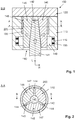
- Fig. 2
- zeigt eine Querschnittsdarstellung des zur Druckgießform der
Fig. 1 gehörenden Kerns. - Fig. 3
- zeigt die Druckgießform aus
Fig. 1 , wobei sich die Kernsegmente nun in ihren Entformungsstellungen befinden. - Fig. 4
- zeigt in einer perspektivischen Darstellung den zum Kern der
Fig. 2 gehörenden Dorn.
- Fig. 1
- shows a sectional view of a die according to the invention with a multi-part core, the core segments are in their casting positions.
- Fig. 2
- shows a cross-sectional view of the die
Fig. 1 belonging core. - Fig. 3
- shows the die
Fig. 1 , with the core segments now in their demolding positions. - Fig. 4
- shows a perspective view of the core of the
Fig. 2 belonging thorn.
Die in
Bei dem Druckgussteil 200 handelt es sich z. B. um einen dünnwandigen Statortopf zur Aufnahme von Statorblechpaketen in einer E-Maschine für den Fahrantrieb (E-Antrieb) eines Kraftfahrzeugs. Einerseits ist das Druckgussteil 200 in Bezug auf seinen Durchmesser (z. B. > 200 mm) vergleichsweise dünnwandig (z. B. < 5 mm). Andererseits werden an das Druckgussteil 200 hohe mechanische Anforderungen gestellt. Die üblicherweise vorzusehenden Formschrägen an der äußeren Kavitätswand und an der inneren Kavitätswand führen abhängig vom Schrägungswinkel zu hohen und ungleichen Wanddicken, wodurch eine erhöhte Gefahr für Fehlstellen besteht.The die-
Bei der erfindungsgemäßen Druckgießform 100 ist der Kern 140 mehrteilig ausgebildet und weist mehrere querbewegliche Kernsegmente 146 sowie einen längs- bzw. axialverschieblich zwischen diesen Kernsegmenten 146 angeordneten Dorn 141 auf. Der Dorn 141 ist, wie aus
Beim Ausfahren des Dorns 141, wozu dieser wie in
Nachdem der Formhohlraum 130 mit Schmelze befüllt ist, wird der Dorn 141, noch bevor das Druckgussteil 200 seine Entformungstemperatur erreicht hat (um die Aufschrumpfkräfte klein zu halten), eingefahren, wozu dieser, wie in
Wie vorausgehend erläutert, werden die Kernsegmente 146 durch Ausfahren des Dorns 141 quer zur Bewegungsachse L des Dorns 140 verschoben und in eine Gießstellung gebracht, wie in
- 100100
- GießformMold
- 110110
- FormhälfteMold half
- 119119
- NutGroove
- 120120
- FormhälfteMold half
- 130130
- FormhohlraumMold cavity
- 140140
- Kerncore
- 141141
- Dornmandrel
- 142142
- Konuscone
- 143143
- RadialstegRadial web
- 144144
- Außenfläche (am Radialsteg)Outer surface (at the radial web)
- 145145
- Taschebag
- 146146
- KernsegmentCore segment
- 147147
- Außenfläche (am Kernsegment)Outer surface (at the core segment)
- 148148
- FormelementShaped element
- 149149
- NutensteinSliding block
- 150150
- Federfeather
- 200200
- GussteilCasting
- LL
- LängsrichtungLongitudinal direction
- RR
- RadialrichtungRadial direction
- SS
- Spaltgap
Claims (10)
der Kern (140) mehrteilig ausgebildet ist und mehrere bewegliche Kernsegmente (146) sowie einen längsverschieblich zwischen den Kernsegmenten (146) angeordneten Dorn (141) aufweist, wobei die Kernsegmente (146) beim Längsverschieben des Dorns (141) quer zur Bewegungsrichtung des Dorns (141) verschoben werden und durch Ausfahren des Dorns (141) in eine Gießstellung bringbar sind und durch Einfahren des Dorns (141) in eine Entformungsstellung bringbar sind.Casting mold (100) for producing a cast part (200) which has at least one inner contour, with:
the core (140) is of multi-part design and has a plurality of movable core segments (146) and a mandrel (141) arranged to be longitudinally displaceable between the core segments (146), the core segments (146) being displaced longitudinally to the direction of movement of the mandrel (141) 141) can be moved and brought into a casting position by extending the mandrel (141) and brought into a demolding position by moving the mandrel (141).
dadurch gekennzeichnet, dass
der Dorn (141) zentral angeordnet ist und die Kernsegmente (146) um den Dorn (141) herum angeordnet sind.Casting mold (100) according to claim 1,
characterized in that
the mandrel (141) is arranged centrally and the core segments (146) are arranged around the mandrel (141).
dadurch gekennzeichnet, dass
der Dorn (141) und die Kernsegmente (146) mit komplementären Schrägflächen ausgebildet sind, die einen Keilschiebermechanismus bilden.Casting mold (100) according to claim 1 or 2,
characterized in that
the mandrel (141) and the core segments (146) are formed with complementary inclined surfaces which form a wedge slide mechanism.
dadurch gekennzeichnet, dass
die Kernsegmente (146) mittels Federn (150) gegen den Dorn (141) vorgespannt sind.Casting mold (100) according to claim 3,
characterized in that
the core segments (146) are prestressed against the mandrel (141) by means of springs (150).
dadurch gekennzeichnet, dass
die Kernsegmente (141) mittels Nutführungen (119, 149) bewegungsgeführt sind.Casting mold (100) according to one of the preceding claims,
characterized in that
the core segments (141) are motion-guided by means of groove guides (119, 149).
dadurch gekennzeichnet, dass
die Kernsegmente (146) mit Formelementen (148) ausgebildet sind, die die Abbildung einer hinterschnittigen Innenkontur ermöglichen.Casting mold (100) according to one of the preceding claims,
characterized in that
the core segments (146) are formed with shaped elements (148) which enable the formation of an undercut inner contour.
dadurch gekennzeichnet, dass
das herzustellende Gussteil (200) einen hohlzylindrischen Bereich aufweist, dessen Innenkontur mit dem mehrteiligen Kern (140) abgebildet wird, wobei der Kern (140) drei bewegliche Kernsegmente (146) aufweist und der Dorn (141) mit drei Taschen (145) ausgebildet ist, in denen diese Kernsegmente (146) angeordnet sind.Casting mold (100) according to one of the preceding claims,
characterized in that
the cast part (200) to be produced has a hollow cylindrical region, the inner contour of which is imaged with the multi-part core (140), the core (140) having three movable core segments (146) and the mandrel (141) having three pockets (145) , in which these core segments (146) are arranged.
dadurch gekennzeichnet, dass
der Dorn (141) drei Radialstege (143) aufweist, die sich zwischen den Taschen (145) erstrecken, wobei die Außenflächen (144) dieser Radialstege (143) zusammen mit den Außenflächen (147) der in Gießstellung befindlichen Kernsegmente (146) die abzubildende Innenkontur definieren.Casting mold (100) according to claim 7,
characterized in that
the mandrel (141) has three radial webs (143) which extend between the pockets (145), the outer surfaces (144) of these radial webs (143) together with the outer surfaces (147) of the core segments (146) in the casting position being the one to be imaged Define inner contour.
dadurch gekennzeichnet, dass
die Außenflächen (144) der Radialstege (143) mit Zugschrägen ausgebildet sind.Casting mold (100) according to claim 8,
characterized in that
the outer surfaces (144) of the radial webs (143) are designed with bevels.
Applications Claiming Priority (1)
| Application Number | Priority Date | Filing Date | Title |
|---|---|---|---|
| DE102018217546.2A DE102018217546A1 (en) | 2018-10-12 | 2018-10-12 | Casting mold for producing a casting, which has at least one inner contour |
Publications (2)
| Publication Number | Publication Date |
|---|---|
| EP3636365A1 true EP3636365A1 (en) | 2020-04-15 |
| EP3636365B1 EP3636365B1 (en) | 2022-06-22 |
Family
ID=68072215
Family Applications (1)
| Application Number | Title | Priority Date | Filing Date |
|---|---|---|---|
| EP19200013.1A Active EP3636365B1 (en) | 2018-10-12 | 2019-09-27 | Casting mould for manufaturing a casting part by having at least one internal contour and the use of such mold |
Country Status (3)
| Country | Link |
|---|---|
| EP (1) | EP3636365B1 (en) |
| CN (1) | CN111036846B (en) |
| DE (1) | DE102018217546A1 (en) |
Families Citing this family (2)
| Publication number | Priority date | Publication date | Assignee | Title |
|---|---|---|---|---|
| DE102020106059A1 (en) | 2020-03-06 | 2021-09-09 | Bayerische Motoren Werke Aktiengesellschaft | Method for producing a cast component and casting station |
| DE102022209863A1 (en) | 2022-09-20 | 2024-03-21 | Volkswagen Aktiengesellschaft | Method for producing a stator assembly with a cooling structure |
Citations (9)
| Publication number | Priority date | Publication date | Assignee | Title |
|---|---|---|---|---|
| DE1937875U (en) * | 1966-03-11 | 1966-05-05 | Krauss Maffei Ag | INJECTION MOLD FOR THERMOPLASTIC PLASTICS PROCESSING INJECTION MOLDING MACHINES. |
| DE2619064A1 (en) * | 1976-05-03 | 1977-11-17 | Geyer & Co | Expanding mould core for mfr. of injection-mouldings - with complicated exterior and/or interior configurations has movable, segmented sleeve to facilitate removal of mouldings |
| US4286766A (en) * | 1980-04-18 | 1981-09-01 | Holdt J W Von | Collapsible mold core |
| US4362291A (en) * | 1980-02-26 | 1982-12-07 | Toshiba Kikai Kabushiki Kaisha | Metal mold for molding hollow article having inwardly tapered side wall |
| US4541605A (en) * | 1983-02-16 | 1985-09-17 | Daiichi-Geyer Kabushiki Kaisha | Metal mold device |
| US4731014A (en) * | 1986-03-12 | 1988-03-15 | Holdt J W Von | Rear opening mold |
| US5403179A (en) * | 1993-10-29 | 1995-04-04 | Ramsey; William C. | Collapsible mold core assembly |
| DE102011011784A1 (en) * | 2011-02-19 | 2012-08-23 | Roth Gmbh Plastic + Form | Collapsible core for use as part of e.g. plastic coating tool, has segments whose contact surfaces form dovetail-shaped guide that is not disrupted from control core, where retaining collars are formed on segments |
| DE102015220980A1 (en) | 2015-10-27 | 2017-04-27 | Zf Friedrichshafen Ag | Mold with multi-part slide for the production of metallic cast components, thus executable casting method and hereby produced planet carrier |
Family Cites Families (19)
| Publication number | Priority date | Publication date | Assignee | Title |
|---|---|---|---|---|
| DE7306433U (en) * | 1974-10-17 | Krauss Maffei Ag | Injection molding tool for manufacturing rectangular hollow bodies with circumferential undercuts | |
| CH215180A (en) * | 1939-02-24 | 1941-06-15 | Elektromotorenfabrik H Loher & | Process for the manufacture of stands for electrical machines. |
| FR1370603A (en) * | 1963-04-05 | 1964-08-28 | Renault | Semi-automatic machine for the shell molding of hollow parts such as pistons |
| FR2409843A1 (en) * | 1977-11-29 | 1979-06-22 | Michelin & Cie | MOLD FOR OBJECTS WITH LOCKED PARTS |
| JPS5938032A (en) * | 1982-08-27 | 1984-03-01 | Hitachi Ltd | Mold for forming mirror cylinder for optical device |
| JPH0614998Y2 (en) * | 1988-03-31 | 1994-04-20 | 山村硝子株式会社 | Mold |
| SE505233C2 (en) * | 1990-07-20 | 1997-07-21 | Hans Mueller | Device for maneuvering jaws, cores and the like contained in compression and injection molding tools |
| DE19745516C2 (en) * | 1997-10-15 | 2000-09-07 | Rkt Rodinger Kunststoff Techni | Multi-part core |
| US20060188601A1 (en) * | 2005-02-18 | 2006-08-24 | Mr. Garry Zydron | Collapsible core using two sleeves and is spring loaded |
| CN2868641Y (en) * | 2005-12-12 | 2007-02-14 | 天津理工大学 | Contraction internal core-drawing device for plastic mould |
| DE102010004227B4 (en) * | 2010-01-09 | 2011-09-01 | Poschmann Holding Gmbh & Co. Kg | Method and device for demolding injection molded hollow bodies with undercuts in the inner contour |
| CN102225602B (en) * | 2011-04-14 | 2013-05-08 | 厦门唯科模塑科技有限公司 | Core pulling device for undercut inner hole |
| CN203739149U (en) * | 2014-03-13 | 2014-07-30 | 常州机电职业技术学院 | Retracted sliding block core-pulling device for product with small diameter |
| FR3022483B1 (en) * | 2014-06-19 | 2017-01-20 | Infiplast | RETRACTABLE CORE SYSTEM FOR MOLDING WORKPIECES |
| DE102015216224A1 (en) * | 2015-08-25 | 2017-03-02 | Volkswagen Aktiengesellschaft | Mold with integrated core bearing bolts and method of making a cast component |
| DE112017001095A5 (en) * | 2016-03-01 | 2018-12-06 | Ksm Castings Group Gmbh | PULLING TOOL AND METHOD FOR POSITIONING AND DE-FORMING A SLIDER INSIDE THE GAS TOOL |
| CN206426322U (en) * | 2017-02-04 | 2017-08-22 | 东莞市弘研精密模具有限公司 | Flexible cored structure |
| CN206484836U (en) * | 2017-02-21 | 2017-09-12 | 中亿腾模塑科技(苏州)有限公司 | A kind of male model applied to plastic mould inside contracts cored structure |
| CN207105503U (en) * | 2017-08-31 | 2018-03-16 | 厦门唯科模塑科技有限公司 | A kind of extra small space internal core pulling mechanism |
-
2018
- 2018-10-12 DE DE102018217546.2A patent/DE102018217546A1/en active Pending
-
2019
- 2019-09-27 EP EP19200013.1A patent/EP3636365B1/en active Active
- 2019-10-12 CN CN201910966836.XA patent/CN111036846B/en active Active
Patent Citations (9)
| Publication number | Priority date | Publication date | Assignee | Title |
|---|---|---|---|---|
| DE1937875U (en) * | 1966-03-11 | 1966-05-05 | Krauss Maffei Ag | INJECTION MOLD FOR THERMOPLASTIC PLASTICS PROCESSING INJECTION MOLDING MACHINES. |
| DE2619064A1 (en) * | 1976-05-03 | 1977-11-17 | Geyer & Co | Expanding mould core for mfr. of injection-mouldings - with complicated exterior and/or interior configurations has movable, segmented sleeve to facilitate removal of mouldings |
| US4362291A (en) * | 1980-02-26 | 1982-12-07 | Toshiba Kikai Kabushiki Kaisha | Metal mold for molding hollow article having inwardly tapered side wall |
| US4286766A (en) * | 1980-04-18 | 1981-09-01 | Holdt J W Von | Collapsible mold core |
| US4541605A (en) * | 1983-02-16 | 1985-09-17 | Daiichi-Geyer Kabushiki Kaisha | Metal mold device |
| US4731014A (en) * | 1986-03-12 | 1988-03-15 | Holdt J W Von | Rear opening mold |
| US5403179A (en) * | 1993-10-29 | 1995-04-04 | Ramsey; William C. | Collapsible mold core assembly |
| DE102011011784A1 (en) * | 2011-02-19 | 2012-08-23 | Roth Gmbh Plastic + Form | Collapsible core for use as part of e.g. plastic coating tool, has segments whose contact surfaces form dovetail-shaped guide that is not disrupted from control core, where retaining collars are formed on segments |
| DE102015220980A1 (en) | 2015-10-27 | 2017-04-27 | Zf Friedrichshafen Ag | Mold with multi-part slide for the production of metallic cast components, thus executable casting method and hereby produced planet carrier |
Also Published As
| Publication number | Publication date |
|---|---|
| CN111036846A (en) | 2020-04-21 |
| EP3636365B1 (en) | 2022-06-22 |
| DE102018217546A1 (en) | 2020-04-16 |
| CN111036846B (en) | 2022-07-22 |
Similar Documents
| Publication | Publication Date | Title |
|---|---|---|
| EP2091678B1 (en) | Casting mould for casting a cast part and use of such a casting mould | |
| DE2336789B2 (en) | Method and tool for demolding a core from an undercut plastic channel profile | |
| DE2619064C3 (en) | Mold core for the manufacture of molded parts | |
| DE102010036609A1 (en) | Die for forging a toothed portion of a rack of a steering device | |
| DE4320644C1 (en) | Method of demoulding hollow injection mouldings with undercuts in the inner contour and an associated mould core | |
| EP3636365B1 (en) | Casting mould for manufaturing a casting part by having at least one internal contour and the use of such mold | |
| DE10058428B4 (en) | Cylinder liner and cylinder block and method for producing the same | |
| EP3401037A1 (en) | Mold for producing a casting core | |
| DE19853803C1 (en) | Apparatus for producing an engine block with cast-in cylinder liners comprises conical seating surfaces which ensure that the ends of the cylinder liners undergoing thermal expansion remain pressed against them | |
| EP2623233B1 (en) | Method for producing hollow aluminium die-cast parts | |
| DE102017131280A1 (en) | A method of manufacturing a molded article and a feeder insert for use in such a method | |
| DE3443723A1 (en) | PLASTIC TUBE AND METHOD AND INJECTION MOLDING MACHINE FOR ITS PRODUCTION | |
| EP1934007B1 (en) | Method for producing an article comprising at least one autonomous moving part and a fixing part | |
| AT510204B1 (en) | SLIDING SLEEVE | |
| DE102017105478A1 (en) | Apparatus for shooting a casting core | |
| EP3771506B1 (en) | Casting method with a shaping contour for producing a core, component and system for producing a component | |
| EP2489491B1 (en) | Method and device for producing ball bearing rings | |
| DE102018127559A1 (en) | Component of an internal combustion engine, in particular cylinder head, mold assembly and method for producing a component of an internal combustion engine | |
| DE3100463A1 (en) | Pressure die-casting method and apparatus for the production of a rotor with radial blades | |
| DE102020116309B3 (en) | Molding tool and method for injection molding hollow bodies of different lengths | |
| DE102022106807A1 (en) | Risers and riser systems for molds | |
| DE102016220359A1 (en) | Tool and process for the production of salt cores | |
| EP4151336A1 (en) | Die casting tool | |
| DE752624C (en) | Process for the production of casting molds | |
| DE2756481A1 (en) | METHOD OF MANUFACTURING A CONTROL TUBE AND CONTROL TUBE TO IT |
Legal Events
| Date | Code | Title | Description |
|---|---|---|---|
| PUAI | Public reference made under article 153(3) epc to a published international application that has entered the european phase |
Free format text: ORIGINAL CODE: 0009012 |
|
| STAA | Information on the status of an ep patent application or granted ep patent |
Free format text: STATUS: THE APPLICATION HAS BEEN PUBLISHED |
|
| AK | Designated contracting states |
Kind code of ref document: A1 Designated state(s): AL AT BE BG CH CY CZ DE DK EE ES FI FR GB GR HR HU IE IS IT LI LT LU LV MC MK MT NL NO PL PT RO RS SE SI SK SM TR |
|
| AX | Request for extension of the european patent |
Extension state: BA ME |
|
| STAA | Information on the status of an ep patent application or granted ep patent |
Free format text: STATUS: REQUEST FOR EXAMINATION WAS MADE |
|
| STAA | Information on the status of an ep patent application or granted ep patent |
Free format text: STATUS: EXAMINATION IS IN PROGRESS |
|
| 17P | Request for examination filed |
Effective date: 20201015 |
|
| RBV | Designated contracting states (corrected) |
Designated state(s): AL AT BE BG CH CY CZ DE DK EE ES FI FR GB GR HR HU IE IS IT LI LT LU LV MC MK MT NL NO PL PT RO RS SE SI SK SM TR |
|
| 17Q | First examination report despatched |
Effective date: 20201112 |
|
| GRAP | Despatch of communication of intention to grant a patent |
Free format text: ORIGINAL CODE: EPIDOSNIGR1 |
|
| STAA | Information on the status of an ep patent application or granted ep patent |
Free format text: STATUS: GRANT OF PATENT IS INTENDED |
|
| INTG | Intention to grant announced |
Effective date: 20220301 |
|
| GRAS | Grant fee paid |
Free format text: ORIGINAL CODE: EPIDOSNIGR3 |
|
| GRAA | (expected) grant |
Free format text: ORIGINAL CODE: 0009210 |
|
| STAA | Information on the status of an ep patent application or granted ep patent |
Free format text: STATUS: THE PATENT HAS BEEN GRANTED |
|
| AK | Designated contracting states |
Kind code of ref document: B1 Designated state(s): AL AT BE BG CH CY CZ DE DK EE ES FI FR GB GR HR HU IE IS IT LI LT LU LV MC MK MT NL NO PL PT RO RS SE SI SK SM TR |
|
| REG | Reference to a national code |
Ref country code: GB Ref legal event code: FG4D Free format text: NOT ENGLISH |
|
| REG | Reference to a national code |
Ref country code: CH Ref legal event code: EP |
|
| REG | Reference to a national code |
Ref country code: DE Ref legal event code: R096 Ref document number: 502019004709 Country of ref document: DE |
|
| REG | Reference to a national code |
Ref country code: AT Ref legal event code: REF Ref document number: 1499438 Country of ref document: AT Kind code of ref document: T Effective date: 20220715 |
|
| REG | Reference to a national code |
Ref country code: IE Ref legal event code: FG4D Free format text: LANGUAGE OF EP DOCUMENT: GERMAN |
|
| REG | Reference to a national code |
Ref country code: LT Ref legal event code: MG9D |
|
| REG | Reference to a national code |
Ref country code: NL Ref legal event code: MP Effective date: 20220622 |
|
| PG25 | Lapsed in a contracting state [announced via postgrant information from national office to epo] |
Ref country code: SE Free format text: LAPSE BECAUSE OF FAILURE TO SUBMIT A TRANSLATION OF THE DESCRIPTION OR TO PAY THE FEE WITHIN THE PRESCRIBED TIME-LIMIT Effective date: 20220622 Ref country code: NO Free format text: LAPSE BECAUSE OF FAILURE TO SUBMIT A TRANSLATION OF THE DESCRIPTION OR TO PAY THE FEE WITHIN THE PRESCRIBED TIME-LIMIT Effective date: 20220922 Ref country code: LT Free format text: LAPSE BECAUSE OF FAILURE TO SUBMIT A TRANSLATION OF THE DESCRIPTION OR TO PAY THE FEE WITHIN THE PRESCRIBED TIME-LIMIT Effective date: 20220622 Ref country code: HR Free format text: LAPSE BECAUSE OF FAILURE TO SUBMIT A TRANSLATION OF THE DESCRIPTION OR TO PAY THE FEE WITHIN THE PRESCRIBED TIME-LIMIT Effective date: 20220622 Ref country code: GR Free format text: LAPSE BECAUSE OF FAILURE TO SUBMIT A TRANSLATION OF THE DESCRIPTION OR TO PAY THE FEE WITHIN THE PRESCRIBED TIME-LIMIT Effective date: 20220923 Ref country code: FI Free format text: LAPSE BECAUSE OF FAILURE TO SUBMIT A TRANSLATION OF THE DESCRIPTION OR TO PAY THE FEE WITHIN THE PRESCRIBED TIME-LIMIT Effective date: 20220622 Ref country code: BG Free format text: LAPSE BECAUSE OF FAILURE TO SUBMIT A TRANSLATION OF THE DESCRIPTION OR TO PAY THE FEE WITHIN THE PRESCRIBED TIME-LIMIT Effective date: 20220922 |
|
| PG25 | Lapsed in a contracting state [announced via postgrant information from national office to epo] |
Ref country code: RS Free format text: LAPSE BECAUSE OF FAILURE TO SUBMIT A TRANSLATION OF THE DESCRIPTION OR TO PAY THE FEE WITHIN THE PRESCRIBED TIME-LIMIT Effective date: 20220622 Ref country code: LV Free format text: LAPSE BECAUSE OF FAILURE TO SUBMIT A TRANSLATION OF THE DESCRIPTION OR TO PAY THE FEE WITHIN THE PRESCRIBED TIME-LIMIT Effective date: 20220622 |
|
| PG25 | Lapsed in a contracting state [announced via postgrant information from national office to epo] |
Ref country code: NL Free format text: LAPSE BECAUSE OF FAILURE TO SUBMIT A TRANSLATION OF THE DESCRIPTION OR TO PAY THE FEE WITHIN THE PRESCRIBED TIME-LIMIT Effective date: 20220622 |
|
| PG25 | Lapsed in a contracting state [announced via postgrant information from national office to epo] |
Ref country code: SM Free format text: LAPSE BECAUSE OF FAILURE TO SUBMIT A TRANSLATION OF THE DESCRIPTION OR TO PAY THE FEE WITHIN THE PRESCRIBED TIME-LIMIT Effective date: 20220622 Ref country code: SK Free format text: LAPSE BECAUSE OF FAILURE TO SUBMIT A TRANSLATION OF THE DESCRIPTION OR TO PAY THE FEE WITHIN THE PRESCRIBED TIME-LIMIT Effective date: 20220622 Ref country code: RO Free format text: LAPSE BECAUSE OF FAILURE TO SUBMIT A TRANSLATION OF THE DESCRIPTION OR TO PAY THE FEE WITHIN THE PRESCRIBED TIME-LIMIT Effective date: 20220622 Ref country code: PT Free format text: LAPSE BECAUSE OF FAILURE TO SUBMIT A TRANSLATION OF THE DESCRIPTION OR TO PAY THE FEE WITHIN THE PRESCRIBED TIME-LIMIT Effective date: 20221024 Ref country code: ES Free format text: LAPSE BECAUSE OF FAILURE TO SUBMIT A TRANSLATION OF THE DESCRIPTION OR TO PAY THE FEE WITHIN THE PRESCRIBED TIME-LIMIT Effective date: 20220622 Ref country code: EE Free format text: LAPSE BECAUSE OF FAILURE TO SUBMIT A TRANSLATION OF THE DESCRIPTION OR TO PAY THE FEE WITHIN THE PRESCRIBED TIME-LIMIT Effective date: 20220622 |
|
| PG25 | Lapsed in a contracting state [announced via postgrant information from national office to epo] |
Ref country code: PL Free format text: LAPSE BECAUSE OF FAILURE TO SUBMIT A TRANSLATION OF THE DESCRIPTION OR TO PAY THE FEE WITHIN THE PRESCRIBED TIME-LIMIT Effective date: 20220622 Ref country code: IS Free format text: LAPSE BECAUSE OF FAILURE TO SUBMIT A TRANSLATION OF THE DESCRIPTION OR TO PAY THE FEE WITHIN THE PRESCRIBED TIME-LIMIT Effective date: 20221022 |
|
| REG | Reference to a national code |
Ref country code: DE Ref legal event code: R097 Ref document number: 502019004709 Country of ref document: DE |
|
| PG25 | Lapsed in a contracting state [announced via postgrant information from national office to epo] |
Ref country code: AL Free format text: LAPSE BECAUSE OF FAILURE TO SUBMIT A TRANSLATION OF THE DESCRIPTION OR TO PAY THE FEE WITHIN THE PRESCRIBED TIME-LIMIT Effective date: 20220622 |
|
| PG25 | Lapsed in a contracting state [announced via postgrant information from national office to epo] |
Ref country code: MC Free format text: LAPSE BECAUSE OF FAILURE TO SUBMIT A TRANSLATION OF THE DESCRIPTION OR TO PAY THE FEE WITHIN THE PRESCRIBED TIME-LIMIT Effective date: 20220622 Ref country code: DK Free format text: LAPSE BECAUSE OF FAILURE TO SUBMIT A TRANSLATION OF THE DESCRIPTION OR TO PAY THE FEE WITHIN THE PRESCRIBED TIME-LIMIT Effective date: 20220622 |
|
| PLBE | No opposition filed within time limit |
Free format text: ORIGINAL CODE: 0009261 |
|
| REG | Reference to a national code |
Ref country code: CH Ref legal event code: PL |
|
| STAA | Information on the status of an ep patent application or granted ep patent |
Free format text: STATUS: NO OPPOSITION FILED WITHIN TIME LIMIT |
|
| REG | Reference to a national code |
Ref country code: BE Ref legal event code: MM Effective date: 20220930 |
|
| 26N | No opposition filed |
Effective date: 20230323 |
|
| P01 | Opt-out of the competence of the unified patent court (upc) registered |
Effective date: 20230523 |
|
| PG25 | Lapsed in a contracting state [announced via postgrant information from national office to epo] |
Ref country code: LU Free format text: LAPSE BECAUSE OF NON-PAYMENT OF DUE FEES Effective date: 20220927 |
|
| PG25 | Lapsed in a contracting state [announced via postgrant information from national office to epo] |
Ref country code: LI Free format text: LAPSE BECAUSE OF NON-PAYMENT OF DUE FEES Effective date: 20220930 Ref country code: IE Free format text: LAPSE BECAUSE OF NON-PAYMENT OF DUE FEES Effective date: 20220927 Ref country code: CH Free format text: LAPSE BECAUSE OF NON-PAYMENT OF DUE FEES Effective date: 20220930 |
|
| PG25 | Lapsed in a contracting state [announced via postgrant information from national office to epo] |
Ref country code: SI Free format text: LAPSE BECAUSE OF FAILURE TO SUBMIT A TRANSLATION OF THE DESCRIPTION OR TO PAY THE FEE WITHIN THE PRESCRIBED TIME-LIMIT Effective date: 20220622 |
|
| PG25 | Lapsed in a contracting state [announced via postgrant information from national office to epo] |
Ref country code: BE Free format text: LAPSE BECAUSE OF NON-PAYMENT OF DUE FEES Effective date: 20220930 |
|
| PGFP | Annual fee paid to national office [announced via postgrant information from national office to epo] |
Ref country code: IT Payment date: 20230920 Year of fee payment: 5 Ref country code: CZ Payment date: 20230922 Year of fee payment: 5 |
|
| PGFP | Annual fee paid to national office [announced via postgrant information from national office to epo] |
Ref country code: FR Payment date: 20230926 Year of fee payment: 5 Ref country code: DE Payment date: 20230930 Year of fee payment: 5 |
|
| PG25 | Lapsed in a contracting state [announced via postgrant information from national office to epo] |
Ref country code: HU Free format text: LAPSE BECAUSE OF FAILURE TO SUBMIT A TRANSLATION OF THE DESCRIPTION OR TO PAY THE FEE WITHIN THE PRESCRIBED TIME-LIMIT; INVALID AB INITIO Effective date: 20190927 |