EP3635862B1 - Gesteuerte lastvorrichtung und herstellungsverfahren für eine gesteuerte lastvorrichtung - Google Patents
Gesteuerte lastvorrichtung und herstellungsverfahren für eine gesteuerte lastvorrichtung Download PDFInfo
- Publication number
- EP3635862B1 EP3635862B1 EP18718812.3A EP18718812A EP3635862B1 EP 3635862 B1 EP3635862 B1 EP 3635862B1 EP 18718812 A EP18718812 A EP 18718812A EP 3635862 B1 EP3635862 B1 EP 3635862B1
- Authority
- EP
- European Patent Office
- Prior art keywords
- load
- feedback
- impedance
- impedance minimum
- electromechanical
- Prior art date
- Legal status (The legal status is an assumption and is not a legal conclusion. Google has not performed a legal analysis and makes no representation as to the accuracy of the status listed.)
- Active
Links
Images

Classifications
-
- H—ELECTRICITY
- H02—GENERATION; CONVERSION OR DISTRIBUTION OF ELECTRIC POWER
- H02K—DYNAMO-ELECTRIC MACHINES
- H02K11/00—Structural association of dynamo-electric machines with electric components or with devices for shielding, monitoring or protection
- H02K11/20—Structural association of dynamo-electric machines with electric components or with devices for shielding, monitoring or protection for measuring, monitoring, testing, protecting or switching
-
- H—ELECTRICITY
- H02—GENERATION; CONVERSION OR DISTRIBUTION OF ELECTRIC POWER
- H02P—CONTROL OR REGULATION OF ELECTRIC MOTORS, ELECTRIC GENERATORS OR DYNAMO-ELECTRIC CONVERTERS; CONTROLLING TRANSFORMERS, REACTORS OR CHOKE COILS
- H02P6/00—Arrangements for controlling synchronous motors or other dynamo-electric motors using electronic commutation dependent on the rotor position; Electronic commutators therefor
- H02P6/10—Arrangements for controlling torque ripple, e.g. providing reduced torque ripple
-
- G—PHYSICS
- G01—MEASURING; TESTING
- G01R—MEASURING ELECTRIC VARIABLES; MEASURING MAGNETIC VARIABLES
- G01R17/00—Measuring arrangements involving comparison with a reference value, e.g. bridge
- G01R17/02—Arrangements in which the value to be measured is automatically compared with a reference value
-
- H—ELECTRICITY
- H02—GENERATION; CONVERSION OR DISTRIBUTION OF ELECTRIC POWER
- H02K—DYNAMO-ELECTRIC MACHINES
- H02K11/00—Structural association of dynamo-electric machines with electric components or with devices for shielding, monitoring or protection
-
- H—ELECTRICITY
- H04—ELECTRIC COMMUNICATION TECHNIQUE
- H04B—TRANSMISSION
- H04B15/00—Suppression or limitation of noise or interference
-
- B—PERFORMING OPERATIONS; TRANSPORTING
- B60—VEHICLES IN GENERAL
- B60L—PROPULSION OF ELECTRICALLY-PROPELLED VEHICLES; SUPPLYING ELECTRIC POWER FOR AUXILIARY EQUIPMENT OF ELECTRICALLY-PROPELLED VEHICLES; ELECTRODYNAMIC BRAKE SYSTEMS FOR VEHICLES IN GENERAL; MAGNETIC SUSPENSION OR LEVITATION FOR VEHICLES; MONITORING OPERATING VARIABLES OF ELECTRICALLY-PROPELLED VEHICLES; ELECTRIC SAFETY DEVICES FOR ELECTRICALLY-PROPELLED VEHICLES
- B60L2270/00—Problem solutions or means not otherwise provided for
- B60L2270/10—Emission reduction
- B60L2270/14—Emission reduction of noise
- B60L2270/147—Emission reduction of noise electro magnetic [EMI]
-
- Y—GENERAL TAGGING OF NEW TECHNOLOGICAL DEVELOPMENTS; GENERAL TAGGING OF CROSS-SECTIONAL TECHNOLOGIES SPANNING OVER SEVERAL SECTIONS OF THE IPC; TECHNICAL SUBJECTS COVERED BY FORMER USPC CROSS-REFERENCE ART COLLECTIONS [XRACs] AND DIGESTS
- Y02—TECHNOLOGIES OR APPLICATIONS FOR MITIGATION OR ADAPTATION AGAINST CLIMATE CHANGE
- Y02T—CLIMATE CHANGE MITIGATION TECHNOLOGIES RELATED TO TRANSPORTATION
- Y02T10/00—Road transport of goods or passengers
- Y02T10/60—Other road transportation technologies with climate change mitigation effect
- Y02T10/64—Electric machine technologies in electromobility
Definitions
- the invention relates to a controlled loading device.
- the invention also relates to a manufacturing method for a controlled load device.
- the DE 10 2004 043 103 B4 describes a power and data distribution system with a motor as a load.
- the motor is connected to a control unit in such a way that an alternating current can be supplied to the motor via wires.
- the DE 10 2004 043 103 B4 an additional neutral wire for the return of current signals.
- Disclosure DE 102012104454A1 relates to a starter comprising a motor which is connected to a power supply line by a motor lead and which generates a torque by means of power supplied by a battery.
- the starter further includes an electromagnetic switch including an electrical contact that is connected to the power supply line via a battery-side terminal and an engine-side terminal.
- the utility model DE 9418 804 U1 discloses an electric drive with a DC voltage electric motor, which is accommodated in a motor housing and has motor windings, and with a motor control circuit, which is connected to the motor windings and has a switching regulator, for controlling the electric motor, which is arranged on a printed circuit board and a ground plane for connecting the printed circuit board has at ground potential.
- the invention relates to a controlled load device with the features of claim 1 and a production method for a controlled load device with the features of claim 14.
- the present invention creates an impedance improvement of an electromechanical connection of the load to the control electronics formed by means of at least the at least one conductor and the first electromechanical feedback component. This brings about a significantly improved feedback of interfering signals, in particular high-frequency interfering signals, from the load into the control electronics.
- the at least one conductor and the first electromechanical feedback component can interact with one another in such a way that a significant improvement in the feedback the high-frequency interference signals is achieved.
- the high-frequency interference signals can thus be "fetched back" into the control electronics more effectively.
- the first electromechanical feedback component the first feedback impedance with the first feedback impedance minimum at the first feedback impedance minimum frequency between 10% of the load impedance minimum frequency and 100% of the load impedance minimum frequency, in particular between 20% of the load impedance minimum frequency and 100% of the Load impedance minimum frequency, especially between 40% of the load impedance minimum frequency and 100% of the load impedance minimum umfrequency.
- the first feedback impedance minimum frequency can thus be so "close" to the load impedance minimum frequency that the at least one conductor and the first electromechanical feedback component arranged parallel to it ensure the desired interaction for the optimized feedback of interference signals.
- the first feedback impedance minimum frequency of the first electromechanical feedback component is preferably established by means of a quality and / or a resonance frequency of the first electromechanical feedback component.
- inexpensive components of the first electromechanical feedback component such as at least one resistor and / or at least one capacitor, can thus be used.
- the controlled load device comprises a first return spring, a first return contact and / or a first screw connection as the first electromechanical return component.
- Inexpensive components can thus be used as the first electromechanical feedback component.
- the controlled load device can also include a second electromechanical feedback component, which is designed to guide or return the high-frequency interference signals from the load to the control electronics.
- the second electromechanical feedback component can also contribute to improving the feedback of the high-frequency interference signals.
- the second electromechanical feedback component preferably has a second feedback impedance with a second feedback impedance minimum at a second feedback minimum impedance frequency less than the load impedance minimum frequency, the second feedback impedance minimum frequency being less than 50% of the load impedance minimum frequency.
- the second feedback impedance minimum frequency of the second electromechanical feedback component can thus be selected relatively freely.
- the controlled load device can also comprise a second feedback spring, a second feedback contact and / or a second screw connection.
- the second electromechanical feedback component can also be designed to be relatively inexpensive and comparatively simple.
- the load can advantageously be a motor, a valve, a light emitting device and / or an electronic device.
- the load can be built into and / or on a vehicle.
- the load can be an electric brake booster motor, a pump motor or a brake system valve.
- the invention described here can thus be used for a large number of different loads. It is pointed out, however, that the training options for the load listed here are only to be interpreted as examples.
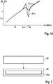
- Figures 1a to 1d show schematic representations and coordinate systems for explaining an embodiment of the controlled load device.
- the means of the Figures 1a to 1d The schematically reproduced controlled load device comprises a load 10 and control electronics 12, which are connected to the load 10 via at least one conductor 14 such that the load 10 can be switched / switched and / or energized via at least one electrical signal transmitted via the at least one conductor 14 / is energized.
- the control electronics 12 can also be referred to as a control device and / or a control circuit board.
- the load 10 is designed as a motor 10, for example as a brushless direct current motor 10 (BLDC, Brushless Direct Current Motor), in particular as a brushless three-phase motor 10.
- the motor 10 can be designed for a clocked motor control.
- the motor 10 is connected to the control electronics 12 via three phase lines U, V and W (as the at least one conductor 14).
- the ability to design the controlled load device is, however, neither limited to a specific load type or a specific motor control nor to a specific design of the at least one conductor 14.
- the load 10 can also be a valve, a light-emitting device (such as a device with at least one light-emitting diode) and / or an electronic device, such as in particular a household appliance, a material processing device (e.g. an electric saw) and / or a high-performance device. It is also pointed out that the examples listed here for the formation of the load 10 are only to be interpreted as examples.
- the control electronics 12 in the example of FIG Figures 1a to 1d still connected to an on-board network 16.
- the lines 16a and 16b of the on-board network 16 are in Fig. 1a only a first line 16a and a second line 16b are outlined by way of example.
- the components 10, 12 and 16 are vehicle-own components 10, 12 and 16, with only one chassis 18 in FIG Fig. 1a is shown.
- the controlled load device described below can advantageously be used primarily on / in a vehicle / motor vehicle. It is therefore advantageous if the load 10 can be built into / on a vehicle / motor vehicle.
- the load can be an electric brake booster motor, a pump motor or a brake system valve.
- a Usability of the controlled load device is not limited to vehicles / motor vehicles.
- interference signals are generated during its operation.
- motor control signals and / or a motor current of the load 10 embodied as motor 10 can parasitically decouple in its housing / motor housing. Reliable routing / feedback of the interference signals, in particular high-frequency interference signals, from the load 10 (directly) into the control electronics 12 is desired.
- a (frequency-dependent) load impedance Z 10 of the load 10 connected to the control electronics 12 via the at least one conductor 14 is shown, with an abscissa of the coordinate system frequencies f (in MHz / megahertz) and an ordinate of the coordinate system an impedance amount
- the physical quantity "impedance” describes a property of a line or a medium during electromechanical wave propagation. If the load 10 is designed as a motor 10, the load impedance Z 10 of the load 10 connected to the control electronics 12 via the at least one conductor 14 can also be referred to as the motor impedance Z 10 .
- an inductance of the at least one conductor 14 and / or a capacitance of a motor winding of the load 10 are significant variables.
- the load impedance Z 10 of the load 10 connected to the control electronics 12 via the at least one conductor 14 has a load impedance minimum at a load impedance minimum frequency f 10 .
- the load impedance minimum frequency f 10 is due to the design. Often the load impedance minimum frequency f 10 is between 5 MHz (megahertz) and 300 MHz (megahertz), often between 70 MHz (megahertz) and 200 MHz (megahertz), sometimes between 80 MHz (megahertz) and 150 MHz (megahertz), for example between 80 MHz (megahertz) and 100 MHz (megahertz).
- the load impedance minimum frequency f 10 is thus in a frequency range in which the routing / return of the high-frequency interference signals from the load 10 into the control electronics 12 is primarily desired.
- the first electromechanical feedback component 20 preferably runs between the load 10 and the control electronics 12 such that the load 10 is also connected to the control electronics 12 via the first electromechanical feedback component 20. This can also be paraphrased by the fact that the first electromechanical feedback component 20 is arranged / formed parallel to the at least one conductor 14.
- the first electromechanical feedback component 20 is not to be understood as a line component for forwarding an electrical signal used to control, switch and / or energize the load 10 from the control electronics 12 to the load 10.
- the first electromechanical feedback component 20 enables an additional connection of the Load 10 to the control electronics 16, which contribute to increasing the routing / feedback of interference signals, in particular high-frequency interference signals, from the load 10 into the control electronics 12.
- a (frequency-dependent) first feedback impedance Z 20 of the first electromechanical feedback component 20 is also shown. It can be seen that the first feedback impedance Z 20 of the first electromechanical feedback component 20 has a first feedback impedance minimum at a first feedback impedance minimum frequency f 20 between 1% of the load impedance minimum frequency f 10 and 100% of the load impedance minimum frequency f 10 .
- a frequency difference ⁇ f between the load impedance minimum frequency f 10 and the first feedback impedance minimum frequency f 20 is also shown.
- the load 10 with the at least one conductor 14 has a first "oscillating circuit" / a first "resonance system” with the load Represents the minimum impedance frequency f 10
- the first electromechanical feedback component 20 can be used as a second "Resonant circuit” / a second "resonance system” with the first feedback impedance minimum frequency f 20 , which due to the comparatively small frequency difference ⁇ f between the load impedance minimum frequency f 10 and the first feedback impedance minimum frequency f 20 with the first "resonant circuit" / first "Resonance system” is coupled.
- the load 10 with the at least one conductor 14 and the first electromechanical feedback component 20 can therefore be described as two “oscillating circuits” / “resonance systems” coupled to one another (or as one "overall oscillating circuit” / “overall resonance system”). High-frequency interference signals can thus be better fed back into the control electronics 12.
- the first electromechanical feedback component 20 therefore enables a compensation connection which specifically eliminates construction-related disadvantages of the connection of the load 10 to the control electronics 12 via the at least one conductor 14.
- a first feedback impedance minimum value (of about 3 ⁇ (Ohm)) of the first feedback impedance minimum of the first feedback impedance Z 20 can be significantly greater than a load impedance minimum value (of about 1 ⁇ (Ohm)) of the load impedance minimum of the load impedance Z Be 10.
- the first feedback impedance minimum frequency f 20 is preferably between 10% of the load impedance minimum frequency f 10 and 100% of the load impedance minimum frequency f 10 , in particular between 20% of the load impedance minimum frequency f 10 and 100% of the load impedance minimum frequency f 10 , especially between 40% of the load impedance minimum frequency f 10 and 100% of the load impedance minimum frequency f 10 .
- the first feedback impedance minimum frequency f 20 of the first electromechanical feedback component 20 can be determined accordingly in a simple and reliable manner by means of a quality and / or a resonance frequency of the first electromechanical feedback component 20 will be.
- at least one physical variable of at least one resistor and / or at least one capacitor of the first electromechanical feedback component 20 can be determined accordingly.
- the controlled load device may include a first return spring, a first return contact, and / or a first screw connection as the first electromechanical return component 20.
- the first electromechanical feedback component 20 can thus be implemented relatively inexpensively with its advantageous properties.
- the controlled load device has the Figures 1a to 1d (in addition to the first electromechanical feedback component 20) a second electromechanical feedback component 22, which is designed to guide or feedback the high-frequency interference signal from the load 10 into the control electronics 12.
- the second electromechanical feedback component 22 also preferably runs between the load 10 and the control electronics 12 such that the load 10 is connected to the control electronics 12 via the second electromechanical feedback component 22.
- the second electromechanical feedback component 22 is formed parallel to the at least one conductor 14 and / or parallel to the first electromechanical feedback component 20.
- the second electromechanical feedback component 22 is not to be understood as a line component for forwarding an electrical signal used to control, switch and / or energize the load 10 from the control electronics 12 to the load 10.
- the second electromechanical feedback component 22 can, for example, be a second feedback spring , a second feedback contact and / or a second screw connection.
- the second electromechanical feedback component 22 can also be designed with a (not shown) second feedback impedance Z 22 (in particular with a second feedback impedance minimum at a second feedback impedance minimum frequency) that the routing / feedback of the high-frequency interference signals from the load 10 in the control electronics 12 is improved / increased.
- the second feedback impedance minimum frequency can be less than 50% of the load impedance minimum frequency f 10 eg less than 30% of the load impedance minimum frequency f 10 , in particular less than 10% of the load impedance minimum frequency f 10 , especially less than 1% of the load impedance minimum frequency f 10 (fixed).
- the second feedback impedance minimum frequency is, for example, in the kHz range. It should be noted that the second feedback impedance minimum is preferably not to be understood as a designed impedance minimum.
- the second electromechanical feedback component 22 can be implemented independently of a design of the first electromechanical feedback component 20.
- a certain geometric expansion / design of the second electromechanical feedback component 22 is not required to improve the routing / feedback of the high-frequency interference signals from the load 10 to the control electronics 12 by means of the first electromechanical feedback component 20.
- An inductance of the second electromechanical feedback component 22 also plays a role in the means of the first electromechanical feedback component 20 had hardly any effect on the interference suppression.
- the at least one conductor 14 with the load 10 each form a "path" for interference signals / high-frequency interference signals between the control electronics 12 and the chassis 18, ie a total of three “paths ".
- the three "paths" are connected in parallel to one another, as by means of the overall parallel connection of the three paths in FIG Figure 1c is shown schematically.
- the load 10 connected to the control electronics 12 via the at least one conductor 14 and the second electromechanical feedback component 22 form a "parallel connection" with a parallel connection impedance maximum at a parallel connection impedance maximum frequency. Due to the superposition of their frequency responses, in this case the “parallel connection” and the first electromechanical feedback component 20 couple to one another and form the overall parallel connection which is optimized with regard to the routing / feedback of interference signals (from the load 10 connected to the control electronics 12 via the at least one conductor 14 and the electromechanical feedback components 20 and 22) with a total impedance Z total with a total impedance minimum at a total impedance minimum frequency f total unequal to the load impedance minimum frequency f 10 .
- the controlled load of the Figures 1a and 1b (due to its design, at least with the first electromechanical feedback component 20) has such an improved feedback that (essentially) no interference signals, in particular (almost) no high-frequency interference signals, flow off to the chassis 18 (or a corresponding ground connection).
- This is indicated by means of a broken and crossed-out arrow 26 in FIG Fig. 1a figuratively reproduced.
- This advantage is even with a (in Fig. 1a not sketched) fastening the load 10 to the chassis 18, such as screwing the load 10 to the chassis 18, guaranteed.
- the design at least with the first electromechanical feedback component 20 is therefore particularly well suited for an electromechanical brake booster (usually screwed to the chassis 18) as the load 10.
- FIG. 13 shows a flowchart for explaining an embodiment of the manufacturing method for a controlled load device.
- the manufacturing method described below can be used, for example, to form the controlled load device explained above. However, a feasibility of the manufacturing method is not limited to this embodiment of the controlled load device.
- a (later) load of the controlled load device is connected to (later) control electronics of the controlled load device via at least one conductor in such a way that the load (during operation of the controlled load device) by means of at least one electrical signal forwarded via the at least one conductor switchable / switched and / or energizable / energized is / is.
- the load connected to the control electronics via the at least one conductor thus has a load impedance with a load impedance minimum at a load impedance minimum frequency.
- step S2 at least one first electromechanical feedback component for guiding or feeding back high-frequency interference signals from the load into the control electronics is formed.
- the manufacturing method described here thus also contributes to better emission dissipation in a controlled load device manufactured with it.
- substep S2a By executing substep S2a, the routing / feedback of the high-frequency interference signals from the load into the control electronics can be improved in such a way that the high-frequency interference is (essentially) prevented from being coupled out to another component surrounding the load.
- the substep S2a there is also no need for a construction-related adaptation or overcoming of the load impedance minimum of the load impedance of the load.
- the first feedback impedance minimum frequency of the first electromechanical feedback component can be determined by means of a quality and / or a resonance frequency of the first electromechanical feedback component.
- at least one resistor and / or at least one capacitor of the first electromechanical feedback component can be used to establish the impedance minimum of the first electromechanical feedback component.
- the second electromechanical feedback component explained above can also be formed in method step S2 (or in a further method step not shown).
- the method steps S1 and S2 can also be carried out in any order, simultaneously or at least at an overlapping time.
Landscapes
- Engineering & Computer Science (AREA)
- Power Engineering (AREA)
- Computer Networks & Wireless Communication (AREA)
- Signal Processing (AREA)
- Microelectronics & Electronic Packaging (AREA)
- Physics & Mathematics (AREA)
- General Physics & Mathematics (AREA)
- Braking Systems And Boosters (AREA)
- Control Of Ac Motors In General (AREA)
- Filters And Equalizers (AREA)
- Electronic Switches (AREA)
- Control Of Electric Motors In General (AREA)
Description
- Die Erfindung betrifft eine gesteuerte Lastvorrichtung. Ebenso betrifft die Erfindung ein Herstellungsverfahren für eine gesteuerte Lastvorrichtung.
- In der
DE 10 2004 043 103 B4 ist ein Strom- und Datenverteilungssystem mit einem Motor als Last beschrieben. Der Motor ist an einem Steuergerät derart angebunden, dass ein Wechselstrom über Drähte an den Motor bereitstellbar ist. Außerdem schlägt dieDE 10 2004 043 103 B4 einen zusätzlichen neutralen Draht zur Rückführung von Stromsignalen vor. - Die Offenlegung
DE 102012104454A1 betrifft einen Anlasser umfassend einen Motor, der durch eine Motorzuleitung mit einer Stromversorgungsleitung verbunden ist und durch von einer Batterie zugeführte Leistung ein Drehmoment erzeugt. Ferner umfasst der Anlasser einen elektromagnetischen Schalter, der einen elektrischen Kontakt einschließt, der mit der Stromversorgungsleitung über eine batterieseitige Klemme und eine motorseitige Klemme verbunden ist. - Das Gebrauchsmuster
DE 9418 804 U1 offenbart einen Elektroantrieb mit einem Gleichspannungs-Elektromotor, der in einem Motorgehäuse untergebracht ist und Motorwicklungen aufweist, und mit einer mit den Motorwicklungen verbundenen, einen Schaltregler aufweisenden Motorsteuerschaltung zur Steuerung des Elektromotors, die auf einer Leiterplatte angeordnet ist und eine Massefläche für den Anschluss der Leiterplatte an Massepotential aufweist. - Die Erfindung betrifft eine gesteuerte Lastvorrichtung mit den Merkmalen des Anspruchs 1 und ein Herstellungsverfahren für eine gesteuerte Lastvorrichtung mit den Merkmalen des Anspruchs 14.
- Die vorliegende Erfindung schafft eine Impedanzverbesserung einer mittels zumindest des mindestens einen Leiters und der ersten elektromechanischen Rückführungskomponente gebildeten elektromechanischen Anbindung der Last an die Steuerelektronik. Dies bewirkt eine deutlich verbesserte Rückführung von Störsignalen, insbesondere von hochfrequenten Störsignalen, aus der Last in die Steuerelektronik.
- Durch die erfindungsgemäße Festlegung der ersten Rückführungs-Impedanzminimumfrequenz der ersten elektromechanischen Rückführungskomponente bezüglich der Last- Impedanzminimumfrequenz der über den mindestens einen Leiter mit der Steuerelektronik verbundenen Last können der mindestens eine Leiter und die erste elektromechanische Rückführungskomponente so miteinander wechselwirken, dass eine deutliche Verbesserung bei der Rückführung der hochfrequenten Störsignale erreicht wird. Die hochfrequenten Störsignale können damit effektiver in die Steuerelektronik "zurückgeholt" werden.
- Beispielsweise kann die erste elektromechanische Rückführungskomponente die erste Rückführungs-Impedanz mit dem ersten Rückführungs-Impedanzminimum bei der ersten Rückführungs-Impedanzminimumfrequenz zwischen 10% der Last-Impedanzminimumfrequenz und 100% der Last-Impedanzminimumfrequenz, insbesondere zwischen 20% der Last-Impedanzminimumfrequenz und 100% der Last-Impedanzminimumfrequenz, speziell zwischen 40% der Last-Impedanzminimumfrequenz und 100% der Last-Impedanzminim umfrequenz, aufweisen. Die erste Rückführungs-Impedanzminimumfrequenz kann somit so "nahe" an der Last-Impedanzminimumfrequenz liegen, dass der mindestens eine Leiter und die parallel dazu angeordnete erste elektromechanische Rückführungskomponente die gewünschte Wechselwirkung zur optimierten Rückführung von Störsignalen sicherstellen.
- Bevorzugter Weise ist die erste Rückführungs-Impedanzminimumfrequenz der ersten elektromechanischen Rückführungskomponente mittels einer Güte und/oder einer Resonanzfrequenz der ersten elektromechanischen Rückführungskomponente festgelegt. Zum Festlegen der ersten Rückführungs-Impedanzminimumfrequenz der ersten elektromechanischen Rückführungskomponente können somit kostengünstige Komponenten der ersten elektromechanischen Rückführungskomponente, wie beispielsweise mindestens ein Widerstand und/oder mindestens ein Kondensator, genutzt werden.
- In einer vorteilhaften Ausführungsform umfasst die gesteuerte Lastvorrichtung eine erste Rückführfeder, einen ersten Rückführungskontakt und/oder eine erste Schraubverbindung als die erste elektromechanische Rückführungskomponente. Als die erste elektromechanische Rückführungskomponente können somit kostengünstige Bauteile eingesetzt werden.
- Als vorteilhafte Weiterbildung kann die gesteuerte Lastvorrichtung zusätzlich zu der ersten elektromechanischen Rückführungskomponente noch eine zweite elektromechanische Rückführungskomponente, welche zur Führung oder Rückführung der hochfrequenten Störsignale aus der Last in die Steuerelektronik ausgebildet ist, umfassen. Auch die zweite elektromechanische Rückführungskomponente kann zur Verbesserung der Rückführung der hochfrequenten Störsignale beitragen.
- In diesem Fall liegt vorteilhafterweise eine Parallelschaltung aus der über den mindestens einen Leiter mit der Steuerelektronik verbundenen Last und der zweiten elektromechanischen Rückführungskomponente vor, welche ein Parallelschaltung-Impedanzmaximum bei einer Parallelschaltung-Impedanzmaximumfrequenz aufweist. Messungen haben gezeigt, dass in diesem Fall die Rückführung von Störsignalen, insbesondere die Rückführung von hochfrequenten Störsignalen, optimiert ist.
- Vorzugsweise weist die zweite elektromechanische Rückführungskomponente eine zweite Rückführungs-Impedanz mit einem zweiten Rückführungs-Impedanzminimum bei einer zweiten Rückführungs-Impedanzminimumfrequenz kleiner als der Last-Impedanzminimumfrequenz auf, wobei die zweite Rückführungs-Impedanzminimumfrequenz kleiner als 50% der Last-Impedanzminimumfrequenz ist. Die zweite Rückführungs-Impedanzminimumfrequenz der zweiten elektromechanischen Rückführungskomponente kann somit relativ frei gewählt werden.
- Auch als die zweite elektromechanische Rückführungskomponente kann die gesteuerte Lastvorrichtung eine zweite Rückführfeder, einen zweiten Rückführungskontakt und/oder eine zweite Schraubverbindung umfassen. Somit kann auch die zweite elektromechanische Rückführungskomponente relativ kostengünstig und vergleichsweise einfach ausgebildet sein.
- Vorteilhafterweise kann die Last ein Motor, ein Ventil, eine Lichtemittiereinrichtung und/oder ein Elektronikgerät sein. Die Last kann in und/oder an einem Fahrzeug verbaubar oder verbaut sein. Insbesondere kann die Last ein elektrischer Bremskraftverstärkermotor, ein Pumpenmotor oder ein Bremssystemventil sein. Die hier beschriebene Erfindung ist somit für eine Vielzahl von verschiedenen Lasten nutzbar. Es wird jedoch darauf hingewiesen, dass die hier aufgezählten Ausbildungsmöglichkeiten für die Last nur beispielhaft zu interpretieren sind.
- Die vorausgehend beschriebenen Vorteile sind auch bei einem Ausführen eines korrespondierenden Herstellungsverfahrens für eine gesteuerte Lastvorrichtung gewährleistet. Es wird ausdrücklich darauf hingewiesen, dass das Herstellungsverfahren gemäß den oben erläuterten Ausführungsformen der gesteuerten Lastvorrichtung weiterbildbar ist.
- Weitere Merkmale und Vorteile der vorliegenden Erfindung werden nachfolgend anhand der Figuren erläutert. Es zeigen:
- Fig. 1a bis 1d
- schematische Darstellungen und Koordinatensysteme zum Erläutern einer Ausführungsform der gesteuerten Lastvorrichtung; und
- Fig. 2
- ein Flussdiagramm zum Erläutern einer Ausführungsform des Herstellungsverfahrens für eine gesteuerte Lastvorrichtung.
-
Fig. 1a bis 1d zeigen schematische Darstellungen und Koordinatensysteme zum Erläutern einer Ausführungsform der gesteuerten Lastvorrichtung. - Die mittels der
Fig. 1a bis 1d schematisch wiedergegebene gesteuerte Lastvorrichtung umfasst eine Last 10 und eine Steuerelektronik 12, welche über mindestens einen Leiter 14 so mit der Last 10 verbunden ist, dass die Last 10 über mindestens ein über den mindestens einen Leiter 14 weitergeleitetes elektrisches Signal schaltbar/geschaltet und/oder bestrombar/bestromt ist. Die Steuerelektronik 12 kann auch als ein Steuergerät und/oder eine Ansteuerleiterplatte bezeichnet werden. Lediglich beispielhaft ist in der Ausführungsform derFig. 1a bis 1d die Last 10 als Motor 10, z.B. als bürstenloser Gleichstrommotor 10 (BLDC, Brushless Direct Current Motor), insbesondere als bürstenloser Drei-Phasen-Motor 10, ausgebildet. Speziell kann der Motor 10 für eine getaktete Motoransteuerung ausgelegt sein. Beispielhaft ist der Motor 10 über drei Phasenleitungen U, V und W (als den mindestens einen Leiter 14) mit der Steuerelektronik 12 verbunden. Eine Ausbildbarkeit der gesteuerten Lastvorrichtung ist jedoch weder auf einen bestimmten Lasttyp oder eine spezielle Motoransteuerung noch auf eine bestimmte Ausbildung des mindestens einen Leiters 14 beschränkt. Außerdem kann die Last 10 auch ein Ventil, eine Lichtemittiereinrichtung (wie z.B. eine Vorrichtung mit mindestens einer lichtemittierenden Diode) und/oder ein Elektronikgerät, wie insbesondere ein Haushaltsgerät, ein Materialverarbeitungsgerät (z.B. eine elektrische Säge) und/oder ein Hochleistungsgerät, sein. Ebenso wird darauf hingewiesen, dass die hier aufgezählten Beispiele zur Ausbildung der Last 10 nur beispielhaft zu interpretieren sind. - Beispielhaft ist die Steuerelektronik 12 in dem Beispiel der
Fig. 1a bis 1d noch an ein Bordnetz 16 angebunden. (Von den Leitungen 16a und 16b des Bordnetzes 16 sind inFig. 1a lediglich eine erste Leitung 16a und eine zweite Leitung 16b beispielhaft skizziert.) Außerdem sind die Komponenten 10, 12 und 16 fahrzeugeigene Komponenten 10, 12 und 16, wobei von den weiteren Fahrzeugkomponenten beispielhaft nur ein Chassis 18 inFig. 1a dargestellt ist. Wie unten genauer erläutert wird, ist die im Weiteren beschriebene gesteuerte Lastvorrichtung vor allem an/in einem Fahrzeug/Kraftfahrzeug vorteilhaft einsetzbar. Somit ist es vorteilhaft, wenn die Last 10 in/an einem Fahrzeug/Kraftfahrzeug verbaubar/verbaut ist. Beispielsweise kann die Last ein elektrischer Bremskraftverstärkermotor, ein Pumpenmotor oder ein Bremssystemventil sein. Es wird jedoch darauf hingewiesen, dass eine Verwendbarkeit der gesteuerten Lastvorrichtung nicht auf Fahrzeuge/Kraftfahrzeuge limitiert ist. - Bedingt durch eine Ansteuerung und eine Konstruktion der Last 10 werden während deren Betrieb als Störsignale bezeichenbare (elektromagnetische) Emissionen erzeugt. Beispielsweise können Motoransteuersignale und/oder ein Motorstrom der als Motor 10 ausgebildeten Last 10 parasitär in deren Gehäuse/Motorgehäuse auskoppeln. Erwünscht ist eine verlässliche Führung/Rückführung der Störsignale, insbesondere hochfrequenter Störsignale, aus der Last 10 (direkt) in die Steuerelektronik 12.
- In das Koordinatensystem der
Fig. 1b ist eine (frequenzabhängige) Last-Impedanz Z10 der über den mindestens einen Leiter 14 mit der Steuerelektronik 12 verbundenen Last 10 eingezeichnet, wobei eine Abszisse des Koordinatensystems Frequenzen f (in MHz/Megahertz) und eine Ordinate des Koordinatensystems einen Impedanzbetrag |Z| (in Ω/Ohm) wiedergeben. Die physikalische Größe "Impedanz" beschreibt eine Eigenschaft einer Leitung oder eines Mediums bei der elektromechanischen Wellenausbreitung. Sofern die Last 10 als Motor 10 ausgebildet ist, kann die Last-Impedanz Z10 der über den mindestens einen Leiter 14 mit der Steuerelektronik 12 verbundenen Last 10 auch als Motorimpedanz Z10 bezeichnet werden. Für die Last-Impedanz Z10 der über den mindestens einen Leiter 14 mit der Steuerelektronik 12 verbundenen Last 10 sind beispielsweise eine Induktivität des mindestens einen Leiters 14 und/oder eine Kapazität einer Motorwicklung der Last 10 signifikante Größen. - Wie in
Fig. 1b erkennbar ist, weist die Last-Impedanz Z10 der über den mindestens einen Leiter 14 mit der Steuerelektronik 12 verbundenen Last 10 ein Last-Impedanzminimum bei einer Last-Impedanzminimumfrequenz f10 auf. Die Last-Impedanzminimumfrequenz f10 ist konstruktionsbedingt. Häufig liegt die Last-Impedanzminimumfrequenz f10 zwischen 5 MHz (Megahertz) und 300 MHz (Megahertz), oft zwischen 70 MHz (Megahertz) und 200 MHz (Megahertz), manchmal zwischen 80 MHz (Megahertz) und 150 MHz (Megahertz), beispielsweise zwischen 80 MHz (Megahertz) und 100 MHz (Megahertz). Damit liegt die Last-Impedanzminimumfrequenz f10 in einem Frequenzbereich, in welchem die Führung/Rückführung der hochfrequenten Störsignale aus der Last 10 in die Steuerelektronik 12 vor allem gewünscht ist. - An der gesteuerten Lastvorrichtung ist deshalb auch eine erste elektromechanische Rückführungskomponente 20 ausgebildet, welche zur Führung oder Rückführung hochfrequenter Störsignale aus der Last 10 in die Steuerelektronik 12 ausgelegt ist. Die erste elektromechanische Rückführungskomponente 20 verläuft vorzugsweise zwischen der Last 10 und der Steuerelektronik 12 so, dass die Last 10 auch über die erste elektromechanische Rückführungskomponente 20 mit der Steuerelektronik 12 verbunden ist. Man kann dies auch damit umschreiben, dass die erste elektromechanische Rückführungskomponente 20 parallel zu dem mindestens einen Leiter 14 angeordnet/ausgebildet ist. (Unter der ersten elektromechanischen Rückführungskomponente 20 ist jedoch keine Leitungskomponente zum Weiterleiten eines zum Steuern, Schalten und/oder Bestromen der Last 10 eingesetzten elektrischen Signals von der Steuerelektronik 12 zu der Last 10 zu verstehen.) Die erste elektromechanische Rückführungskomponente 20 ermöglicht eine zusätzliche Anbindung der Last 10 an die Steuerelektronik 16, welche zur Steigerung der Führung/Rückführung von Störsignalen, insbesondere von hochfrequenten Störsignalen, aus der Last 10 in die Steuerelektronik 12 beiträgt.
- In das Koordinatensystem der
Fig. 1b ist auch eine (frequenzabhängige) erste Rückführungs-Impedanz Z20 der ersten elektromechanischen Rückführungskomponente 20 eingezeichnet. Erkennbar ist, dass die erste Rückführungs-Impedanz Z20 der ersten elektromechanischen Rückführungskomponente 20 ein erstes Rückführungs-Impedanzminimum bei einer ersten Rückführungs-Impedanzminimumfrequenz f20 zwischen 1% der Last-Impedanzminimumfrequenz f10 und 100% der Last-Impedanzminimumfrequenz f10 aufweist. (Eine Frequenzdifferenz Δf zwischen der Last-Impedanzminimumfrequenz f10 und der ersten Rückführungs-Impedanzminimumfrequenz f20 ist ebenfalls eingezeichnet.) Während somit die Last 10 mit dem mindestens einen Leiter 14 einen ersten "Schwingkreis"/ein erstes "Resonanzsystem" mit der Last-Impedanzminimumfrequenz f10 darstellt, kann die erste elektromechanische Rückführungskomponente 20 als ein zweiter "Schwingkreis"/ein zweites "Resonanzsystem" mit der ersten Rückführungs-Impedanzminimumfrequenz f20 bezeichnet werden, welches aufgrund der vergleichsweise geringen Frequenzdifferenz Δf zwischen der Last-Impedanzminimumfrequenz f10 und der ersten Rückführungs-Impedanzminimumfrequenz f20 mit dem ersten "Schwingkreis"/ersten "Resonanzsystem" gekoppelt ist. Die Last 10 mit dem mindestens einen Leiter 14 und die erste elektromechanische Rückführungskomponente 20 können deshalb als zwei miteinander gekoppelte "Schwingkreise"/"Resonanzsysteme" (bzw. als ein "Gesamt-Schwingkreise"/"Gesamt-Resonanzsystem") umschrieben werden. Somit können hochfrequente Störsignale besser in die Steuerelektronik 12 rückgeführt werden. Die erste elektromechanische Rückführungskomponente 20 ermöglicht deshalb eine Kompensationsanbindung, welche gezielt konstruktionsbedingte Nachteile der Anbindung der Last 10 an die Steuerelektronik 12 über den mindestens einen Leiter 14 behebt. - Aufgrund der verbesserten Rückführung der hochfrequenten Störsignale aus der Last 10 in die Steuerelektronik 12 ist eine Einleitung der hochfrequenten Störsignale in das Chassis 18 oder eine weitere Fahrzeugkomponenten (im Wesentlichen) unterbunden. Deshalb muss nicht/kaum befürchtet werden, dass die hochfrequenten Störsignale eine große Schleife durch das Chassis 18 und das Bordnetz 16 zur Steuerelektronik 12 zurücklaufen.
- Ein erster Rückführungs-Impedanzminimumwert (von etwa 3Ω (Ohm)) des ersten Rückführungs-Impedanzminimums der ersten Rückführungs-Impedanz Z20 kann deutlich größer als ein Last-Impedanzminimumwert (von etwa 1Ω (Ohm)) des Last-Impedanzminimums der Last-Impedanz Z10 sein. Vorzugsweise liegt die erste Rückführungs-Impedanzminimumfrequenz f20 zwischen 10% der Last-Impedanzminimumfrequenz f10 und 100% der Last-Impedanzminimumfrequenz f10, insbesondere zwischen 20% der Last-Impedanzminimumfrequenz f10 und 100% der Last-Impedanzminimumfrequenz f10, speziell zwischen 40% der Last-Impedanzminimumfrequenz f10 und 100% der Last-Impedanzminimumfrequenz f10. Die erste Rückführungs-Impedanzminimumfrequenz f20 der ersten elektromechanischen Rückführungskomponente 20 kann auf einfache Weise und verlässlich mittels einer Güte und/oder einer Resonanzfrequenz der ersten elektromechanischen Rückführungskomponente 20 entsprechend festgelegt sein/werden. Dazu kann mindestens eine physikalische Größe von mindestens einem Widerstand und/oder mindestens einem Kondensator der ersten elektromechanischen Rückführungskomponente 20 entsprechend festgelegt sein/werden.
- Die gesteuerte Lastvorrichtung kann eine erste Rückführfeder, einen ersten Rückführungskontakt und/oder eine erste Schraubverbindung als die erste elektromechanische Rückführungskomponente 20 umfassen. Die erste elektromechanische Rückführungskomponente 20 ist damit relativ kostengünstig mit ihren vorteilhaften Eigenschaften realisierbar.
- Außerdem weist die gesteuerte Lastvorrichtung der
Fig. 1a bis 1d (zusätzlich zu der ersten elektromechanischen Rückführungskomponente 20) noch eine zweite elektromechanische Rückführungskomponente 22, welche zur Führung oder Rückführung der hochfrequenten Störsignal aus der Last 10 in die Steuerelektronik 12 ausgebildet ist, auf. Auch die zweite elektromechanische Rückführungskomponente 22 verläuft vorzugsweise zwischen der Last 10 und der Steuerelektronik 12 so, dass die Last 10 über die zweite elektromechanische Rückführungskomponente 22 mit der Steuerelektronik 12 verbunden ist. In diesem Fall ist die zweite elektromechanische Rückführungskomponente 22 parallel zu dem mindestens einen Leiter 14 und/oder parallel zu der ersten elektromechanischen Rückführungskomponente 20 ausgebildet. (Unter der zweiten elektromechanischen Rückführungskomponente 22 ist aber keine Leitungskomponente zum Weiterleiten eines zum Steuern, Schalten und/oder Bestromen der Last 10 eingesetzten elektrischen Signals von der Steuerelektronik 12 zu der Last 10 zu verstehen.) Die zweite elektromechanische Rückführungskomponente 22 kann z.B. eine zweite Rückführfeder, ein zweiter Rückführungskontakt und/oder eine zweite Schraubverbindung sein. Auch die zweite elektromechanische Rückführungskomponente 22 kann so mit einer (nicht dargestellten) zweiten Rückführungs-Impedanz Z22 (insbesondere mit einem zweiten Rückführungs-Impedanzminimum bei einer zweiten Rückführungs-Impedanzminimumfrequenz) ausgebildet sein, dass die Führung/Rückführung der hochfrequenten Störsignale aus der Last 10 in die Steuerelektronik 12 verbessert/gesteigert ist. Beispielsweise kann dazu die zweite Rückführungs-Impedanzminimumfrequenz kleiner als 50% der Last-Impedanzminimumfrequenz f10 z.B. kleiner als 30% der Last-Impedanzminimumfrequenz f10, insbesondere kleiner als 10% der Last-Impedanzminimumfrequenz f10,speziell kleiner als 1% der Last-Impedanzminimumfrequenz f10, (festgelegt) sein. (In dem wiedergegebenen Beispiel liegt die zweite Rückführungs-Impedanzminimumfrequenz z.B. im kHz-Bereich). Es wird darauf hingewiesen, dass unter dem zweiten Rückführungs-Impedanzminimum vorzugsweise kein designtes Impedanzminimum zu verstehen ist. - Es wird auch darauf hingewiesen, dass die zweite elektromechanische Rückführungskomponente 22 unabhängig von einer Ausbildung der ersten elektromechanischen Rückführungskomponente 20 realisierbar ist. Eine bestimmte geometrische Ausdehnung/Ausbildung der zweiten elektromechanischen Rückführungskomponente 22 ist nicht erforderlich zur Verbesserung der Führung/Rückführung der hochfrequenten Störsignale von der Last 10 zu der Steuerelektronik 12 mittels der ersten elektromechanischen Rückführungskomponente 20. Auch eine Induktivität der zweiten elektromechanischen Rückführungskomponente 22 spielt bei der mittels der ersten elektromechanischen Rückführungskomponente 20 bewirkten Entstörwirkung kaum eine Rolle.
- Wie in
Fig. 1c schematisch wiedergegeben ist, bilden der mindestens eine Leiter 14 mit der Last 10, die erste elektromechanische Rückführungskomponente 20 und die zweite elektromechanische Rückführungskomponente 22 jeweils einen "Pfad" für Störsignale/hochfrequente Störsignale zwischen der Steuerelektronik 12 und dem Chassis 18, d.h. insgesamt drei "Pfade". Die drei "Pfade" sind parallel zueinander geschaltet, wie mittels der Gesamt-Parallelschaltung aus den drei Pfaden derFig. 1c schematisch wiedergegeben ist. - Die über den mindestens einen Leiter 14 mit der Steuerelektronik 12 verbundene Last 10 und die zweite elektromechanische Rückführungskomponente 22 bilden eine "Parallelschaltung" mit einem Parallelschaltung-Impedanzmaximum bei einer Parallelschaltung-Impedanzmaximumfrequenz. Aufgrund der Überlagerung ihrer Frequenzgänge koppeln in diesem Fall die "Parallelschaltung" und die erste elektromechanische Rückführungskomponente 20 miteinander und bilden die bezüglich der Führung/Rückführung von Störsignalen optimierte Gesamt-Parallelschaltung (aus der über den mindestens einen Leiter 14 mit der Steuerelektronik 12 verbundenen Last 10 und den elektromechanischen Rückführungskomponenten 20 und 22) mit einer Gesamt-Impedanz Ztotal mit einem Gesamt-Impedanzminimum bei einer Gesamt-Impedanzminimumfrequenz ftotal ungleich der Last-Impedanzminimumfrequenz f10.
- In das Koordinatensystem der
Fig. 1d sind die (ungedämpfte) Gesamt-Impedanz Ztotal und eine gedämpfte Gesamt-Impedanz Ztotal-d eingezeichnet, wobei eine Abszisse des Koordinatensystems Frequenzen f (in MHz/Megahertz) und eine Ordinate des Koordinatensystems einen Impedanzbetrag |Z| (in Ω/Ohm) wiedergeben. Erkennbar ist, dass die "Zusammenschaltung" die Gesamt-Impedanz Ztotal mit einem "neuen" Maximum und einem "neuen" Minimum ergibt. Die "Zusammenschaltung" bewirkt somit einen verbesserten Rückführungspfad zur Rückführung von Emissionen von Störungen/hochfrequenten Störungen im Frequenzbereich der Last-Impedanzminimumfrequenz f10, wie mittels eines (dicken) Pfeils 24 inFig. 1a schematisch dargestellt ist. Durch die gedämpfte Gesamt-Impedanz Ztotal-d kann außerdem eine weniger starke Ausbildung des "neuen" Maximums und des "neuen" Minimums bewirkt werden. - Es wird hier auch darauf hingewiesen, dass die gesteuerte Last der
Fig. 1a und 1b (aufgrund ihrer Ausbildung zumindest mit der ersten elektromechanischen Rückführungskomponente 20) eine derart verbesserte Rückführung aufweist, dass (im Wesentlichen) keine Störsignale, insbesondere (nahezu) keine hochfrequenten Störsignale, an das Chassis 18 (bzw. eine entsprechende Masseanbindung) abfließen. Dies ist mittels eines durchbrochenen und durchgestrichenen Pfeils 26 inFig. 1a bildlich wiedergegeben. Dieser Vorteil ist selbst bei einem (inFig. 1a nicht skizzierten) Befestigen der Last 10 an dem Chassis 18, wie z.B. einem Festschrauben der Last 10 an dem Chassis 18, gewährleistet. Die Ausbildung zumindest mit der ersten elektromechanischen Rückführungskomponente 20 eignet sich deshalb besonders gut für einen (in der Regel an dem Chassis 18 festgeschraubten) elektromechanischen Bremskraftverstärker als Last 10. -
Fig. 2 zeigt ein Flussdiagramm zum Erläutern einer Ausführungsform des Herstellungsverfahrens für eine gesteuerte Lastvorrichtung. - Das im Weiteren beschriebene Herstellungsverfahren kann beispielsweise zum Bilden der oben erläuterten gesteuerten Lastvorrichtung genutzt werden. Eine Ausführbarkeit des Herstellungsverfahrens ist jedoch nicht auf diese Ausführungsform der gesteuerten Lastvorrichtung beschränkt.
- In einem Verfahrensschritt S1 wird eine (spätere) Last der gesteuerten Lastvorrichtung über mindestens einen Leiter so mit einer (späteren) Steuerelektronik der gesteuerten Lastvorrichtung, dass die Last (während eines Betriebs der gesteuerten Lastvorrichtung) mittels mindestens eines über den mindestens einen Leiter weitergeleiteten elektrischen Signals schaltbar/geschaltet und/oder bestrombar/bestromt ist/wird. Während des Betriebs der gesteuerten Lastvorrichtung weist die über den mindestens einen Leiter mit der Steuerelektronik verbundene Last damit eine Last-Impedanz mit einem Last-Impedanzminimum bei einer Last-Impedanzminimumfrequenz auf.
- In einem weiteren Verfahrensschritt S2 wird zumindest eine erste elektromechanische Rückführungskomponente zur Führung oder Rückführung hochfrequenter Störsignal aus der Last in die Steuerelektronik ausgebildet. In einem Teilschritt S2a des Verfahrensschritts S2 wird eine erste Rückführungs-Impedanz der ersten elektromechanischen Rückführungskomponente mit einem ersten Rückführungs-Impedanzminimum bei einer ersten Rückführungs-Impedanzminimumfrequenz zwischen 1% der Last-Impedanzminimumfrequenz (f10) und 100% der Last-Impedanzminimumfrequenz (f10)festgelegt,. Damit trägt auch das hier beschriebene Herstellungsverfahren zur besseren Emissions-Abführung bei einer damit hergestellten gesteuerten Lastvorrichtung bei. Durch ein Ausführen des Teilschritts S2a kann die Führung/Rückführung der hochfrequenten Störsignale aus der Last in die Steuerelektronik so verbessert werden, dass eine Auskoppelung der hochfrequenten Störungen in eine andere die Last umgebende Komponente (im Wesentlichen) unterbunden ist. Bei einem Ausführen des Teilschritts S2a entfällt auch eine Notwendigkeit einer konstruktionsbedingten Anpassung oder Überwindung des Last-Impedanzminimums der Last-Impedanz der Last.
- Beispielsweise kann im Teilschritt S2a die erste Rückführungs-Impedanzminimumfrequenz der ersten elektromechanischen Rückführungskomponente mittels einer Güte und/oder einer Resonanzfrequenz der ersten elektromechanischen Rückführungskomponente festgelegt werden. Zum Festlegen des Impedanzminimums der ersten elektromechanischen Rückführungskomponente können beispielsweise mindestens ein Widerstand und/oder mindestens ein Kondensator der ersten elektromechanischen Rückführungskomponente genutzt werden.
- Optionaler Weise kann auch die oben erläuterte zweite elektromechanische Rückführungskomponente in dem Verfahrensschritt S2 (bzw. in einem nichtdargestellten weiteren Verfahrensschritt) ebenfalls ausgebildet werden. Die Verfahrensschritte S1 und S2 können auch in beliebiger Reihenfolge, gleichzeitig oder zumindest zeitlich überschneidend ausgeführt werden.
Claims (15)
- Gesteuerte Lastvorrichtung mit:einer Last (10);einer Steuerelektronik (12), welche über mindestens einen Leiter (14) so mit der Last (10) verbunden ist, dass die Last (10) über mindestens ein über den mindestens einen Leiter (14) weitergeleitetes elektrisches Signal schaltbar und/oder bestrombar ist,wobei die über den mindestens einen Leiter (14) mit der Steuerelektronik (12) verbundene Last (10) eine Last-Impedanz (Z10) mit einem Last-Impedanzminimum bei einer Last-Impedanzminimumfrequenz (f10) aufweist; undzumindest einer ersten elektromechanischen Rückführungskomponente (20), welche zur Führung oder Rückführung hochfrequenter Störsignale aus der Last (10) in die Steuerelektronik (12) ausgebildet ist;dadurch gekennzeichnet, dassdie erste elektromechanische Rückführungskomponente (20) eine erste Rückführungs-Impedanz (Z20) mit einem ersten Rückführungs-Impedanzminimum bei einer ersten Rückführungs-Impedanzminimumfrequenz (f20) zwischen 1% der Last-Impedanzminimumfrequenz (f10) und 100% der Last-Impedanzminimumfrequenz (f10) aufweist.
- Gesteuerte Lastvorrichtung nach Anspruch 1, wobei die erste elektromechanische Rückführungskomponente (20) die erste Rückführungs-Impedanz (Z20) mit dem ersten Rückführungs-Impedanzminimum bei der ersten Rückführungs-Impedanzminimumfrequenz (f20) zwischen 10% der Last-Impedanzminimumfrequenz (f10) und 100% der Last-Impedanzminimumfrequenz (f10) aufweist.
- Gesteuerte Lastvorrichtung nach Anspruch 2, wobei die erste elektromechanische Rückführungskomponente (20) die erste Rückführungs-Impedanz (Z20) mit dem ersten Rückführungs-Impedanzminimum bei der ersten Rückführungs-Impedanzminimumfrequenz (f20) zwischen 20% der Last-Impedanzminimumfrequenz (f10) und 100% der Last-Impedanzminimumfrequenz (f10) aufweist.
- Gesteuerte Lastvorrichtung nach Anspruch 3, wobei die erste elektromechanische Rückführungskomponente (20) die erste Rückführungs-Impedanz (Z20) mit dem ersten Rückführungs-Impedanzminimum bei der ersten Rückführungs-Impedanzminimumfrequenz (f20) zwischen 40% der Last-Impedanzminimumfrequenz (f10) und 100% der Last-Impedanzminimumfrequenz (f10) aufweist.
- Gesteuerte Lastvorrichtung nach einem der vorhergehenden Ansprüche, wobei die erste Rückführungs-Impedanzminimumfrequenz (f20) der ersten elektromechanischen Rückführungskomponente (20) mittels einer Güte und/oder einer Resonanzfrequenz der ersten elektromechanischen Rückführungskomponente (20) festgelegt ist.
- Gesteuerte Lastvorrichtung nach einem der vorhergehenden Ansprüche, wobei die gesteuerte Lastvorrichtung eine erste Rückführfeder, einen ersten Rückführungskontakt und/oder eine erste Schraubverbindung als die erste elektromechanische Rückführungskomponente (20) umfasst.
- Gesteuerte Lastvorrichtung nach einem der vorhergehenden Ansprüche, wobei die gesteuerte Lastvorrichtung zusätzlich zu der ersten elektromechanischen Rückführungskomponente (20) noch eine zweite elektromechanische Rückführungskomponente (22), welche zur Führung oder Rückführung der hochfrequenten Störsignale aus der Last (10) in die Steuerelektronik (12) ausgebildet ist, umfasst.
- Gesteuerte Lastvorrichtung nach Anspruch 7, wobei eine Parallelschaltung aus der über den mindestens einen Leiter (14) mit der Steuerelektronik (12) verbundenen Last (10) und der zweiten elektromechanischen Rückführungskomponente (22) ein Parallelschaltung-Impedanzmaximum bei einer Parallelschaltung-Impedanzmaximumfrequenz aufweist.
- Gesteuerte Lastvorrichtung nach Anspruch 7 oder 8, wobei die zweite elektromechanische Rückführungskomponente (22) eine zweite Rückführungs-Impedanz (Z22) mit einem zweiten Rückführungs-Impedanzminimum bei einer zweiten Rückführungs-Impedanzminimumfrequenz kleiner als der Last-Impedanzminimumfrequenz (f10) aufweist, und wobei die zweite Rückführungs-Impedanzminimumfrequenz kleiner als 50% der Last-Impedanzminimumfrequenz (f10) ist.
- Gesteuerte Lastvorrichtung nach einem der Ansprüche 7 bis 9, wobei die gesteuerte Lastvorrichtung eine zweite Rückführfeder, einen zweiten Rückführungskontakt und/oder eine zweite Schraubverbindung als die zweite elektromechanische Rückführungskomponente (22) umfasst.
- Gesteuerte Lastvorrichtung nach einem der vorhergehenden Ansprüche, wobei die Last (10) ein Motor (10), ein Ventil, eine Lichtemittiereinrichtung und/oder ein Elektronikgerät ist.
- Gesteuerte Lastvorrichtung nach einem der vorhergehenden Ansprüche, wobei die Last (10) in und/oder an einem Fahrzeug verbaubar oder verbaut ist.
- Gesteuerte Lastvorrichtung nach Anspruch 12, wobei die Last (10) ein elektrischer Bremskraftverstärkermotor, ein Pumpenmotor oder ein Bremssystemventil ist.
- Herstellungsverfahren für eine gesteuerte Lastvorrichtung mit den Schritten:Verbinden einer Last (10) der gesteuerten Lastvorrichtung über mindestens einen Leiter (14) so mit einer Steuerelektronik (12) der gesteuerten Lastvorrichtung (S1), dass die Last (10) mittels mindestens eines über den mindestens einen Leiter (14) weitergeleiteten elektrischen Signals schaltbar und/oder bestrombar ist, wobei die über den mindestens einen Leiter (14) mit der Steuerelektronik (12) verbundene Last (10) eine Last-Impedanz (Z10) mit einem Last-Impedanzminimum bei einer Last-Impedanzminimumfrequenz (f10) aufweist;
undAusbilden zumindest einer ersten elektromechanischen Rückführungskomponente (20) zur Führung oder Rückführung hochfrequenter Störsignale aus der Last (10) in die Steuerelektronik (12) (S2);gekennzeichnet durch den Schritt:
Festlegen einer ersten Rückführungs-Impedanz (Z20) der ersten elektromechanischen Rückführungskomponente (20) mit einem ersten Rückführungs-Impedanzminimum bei einer ersten Rückführungs-Impedanzminimumfrequenz (f20) zwischen 1% der Last-Impedanzminimumfrequenz (f10) und 100% der Last-Impedanzminimumfrequenz (f10) . - Herstellungsverfahren nach Anspruch 14, wobei die erste Rückführungs-Impedanzminimumfrequenz (f20) der ersten elektromechanischen Rückführungskomponente (20) mittels einer Güte und/oder einer Resonanzfrequenz der ersten elektromechanischen Rückführungskomponente (20) festgelegt wird.
Applications Claiming Priority (2)
| Application Number | Priority Date | Filing Date | Title |
|---|---|---|---|
| DE102017209742.6A DE102017209742A1 (de) | 2017-06-09 | 2017-06-09 | Gesteuerte Lastvorrichtung und Herstellungsverfahren für eine gesteuerte Lastvorrichtung |
| PCT/EP2018/059996 WO2018224213A1 (de) | 2017-06-09 | 2018-04-19 | Gesteuerte lastvorrichtung und herstellungsverfahren für eine gesteuerte lastvorrichtung |
Publications (2)
| Publication Number | Publication Date |
|---|---|
| EP3635862A1 EP3635862A1 (de) | 2020-04-15 |
| EP3635862B1 true EP3635862B1 (de) | 2021-12-22 |
Family
ID=62025860
Family Applications (1)
| Application Number | Title | Priority Date | Filing Date |
|---|---|---|---|
| EP18718812.3A Active EP3635862B1 (de) | 2017-06-09 | 2018-04-19 | Gesteuerte lastvorrichtung und herstellungsverfahren für eine gesteuerte lastvorrichtung |
Country Status (6)
| Country | Link |
|---|---|
| US (1) | US10978938B2 (de) |
| EP (1) | EP3635862B1 (de) |
| JP (1) | JP6934539B2 (de) |
| CN (1) | CN110679084B (de) |
| DE (1) | DE102017209742A1 (de) |
| WO (1) | WO2018224213A1 (de) |
Family Cites Families (16)
| Publication number | Priority date | Publication date | Assignee | Title |
|---|---|---|---|---|
| JPH01186101A (ja) * | 1988-01-21 | 1989-07-25 | Mitsubishi Electric Corp | 電気車制御装置 |
| EP0336530B1 (de) * | 1988-04-07 | 1994-05-18 | Automotive Components Dunstable Limited | Funkentstörung |
| JP2600558B2 (ja) * | 1991-04-19 | 1997-04-16 | 三菱電機株式会社 | 磁気記録再生装置における磁気ヘッド位置制御装置 |
| DE9418804U1 (de) * | 1994-11-23 | 1995-01-19 | Fa. J. Eberspächer, 73730 Esslingen | Elektroantrieb |
| JP2000207857A (ja) * | 1999-01-14 | 2000-07-28 | Hitachi Ltd | 磁気ディスク装置 |
| JP2001196192A (ja) * | 2000-01-13 | 2001-07-19 | Toshiba Lighting & Technology Corp | 高周波電源装置、放電ランプ点灯装置および照明装置 |
| US7034662B2 (en) | 2003-09-15 | 2006-04-25 | Rockwell Automation Technologies, Inc. | Multi-function integrated automation cable system and method |
| JP2007113568A (ja) | 2005-09-22 | 2007-05-10 | Denso Corp | 常時噛合い式スタータ |
| JP2007259578A (ja) * | 2006-03-23 | 2007-10-04 | Mitsubishi Electric Corp | 電力変換装置 |
| US7309973B2 (en) * | 2006-04-24 | 2007-12-18 | Power Conservation Ltd | Mitigation of harmonic currents and conservation of power in non-linear load systems |
| DE102007012413A1 (de) * | 2007-03-15 | 2008-09-18 | Vossloh-Schwabe Deutschland Gmbh | Vorschaltgerät mit verbesserter EMV-Verträglichkeit |
| US8289664B2 (en) * | 2010-03-08 | 2012-10-16 | Pass & Seymour, Inc. | Protective device for an electrical supply facility |
| JP2012246905A (ja) * | 2011-05-31 | 2012-12-13 | Denso Corp | スタータ |
| JP6231316B2 (ja) * | 2013-07-18 | 2017-11-15 | 株式会社Soken | 車載電子機器の接地構造 |
| DE102013224458A1 (de) * | 2013-11-28 | 2015-05-28 | Robert Bosch Gmbh | Entstörfilter für einen Gleichstrommotor und Gleichstrommotor |
| CN105992956B (zh) * | 2014-02-19 | 2018-11-06 | 日产自动车株式会社 | 阻抗测定装置和阻抗测定装置的控制方法 |
-
2017
- 2017-06-09 DE DE102017209742.6A patent/DE102017209742A1/de not_active Withdrawn
-
2018
- 2018-04-19 US US16/618,843 patent/US10978938B2/en active Active
- 2018-04-19 CN CN201880037935.3A patent/CN110679084B/zh active Active
- 2018-04-19 WO PCT/EP2018/059996 patent/WO2018224213A1/de not_active Ceased
- 2018-04-19 EP EP18718812.3A patent/EP3635862B1/de active Active
- 2018-04-19 JP JP2019566751A patent/JP6934539B2/ja active Active
Also Published As
| Publication number | Publication date |
|---|---|
| EP3635862A1 (de) | 2020-04-15 |
| JP2020522939A (ja) | 2020-07-30 |
| CN110679084A (zh) | 2020-01-10 |
| JP6934539B2 (ja) | 2021-09-15 |
| CN110679084B (zh) | 2023-07-18 |
| WO2018224213A1 (de) | 2018-12-13 |
| US20200136475A1 (en) | 2020-04-30 |
| DE102017209742A1 (de) | 2018-12-13 |
| US10978938B2 (en) | 2021-04-13 |
Similar Documents
| Publication | Publication Date | Title |
|---|---|---|
| DE102016108232B4 (de) | Mechanisches Relais und Festkörperrelais zum Steuern von Heizelementen | |
| EP3580825B1 (de) | Aktiver filter für bipolare spannungsquellen | |
| DE102022200377A1 (de) | Steuerungseinheit-integriertes-motormodul zum fahren eines elektrisch verstellbaren sitzes | |
| DE102008061630A1 (de) | Systeme und Verfahren zum Vorladen von Aufwärtswandlern bei DC/DC-Leistungswandlern | |
| DE102014109206A1 (de) | Sensorschnittstellensysteme und -verfahren | |
| DE102014212804B4 (de) | Aktuator mit Positionssensor | |
| EP3635862B1 (de) | Gesteuerte lastvorrichtung und herstellungsverfahren für eine gesteuerte lastvorrichtung | |
| DE112017002602B4 (de) | Elektronische Steuereinheit, Fahrzeug und Verwendung der elektronischen Steuereinheit | |
| EP1661244A1 (de) | Vorrichtung zur berü hrungslosen energie übertragung | |
| EP0350783A2 (de) | Vorrichtung zum Betrieb von an das Gleichstrombordnetz von mobilen Einheiten angeschlossenen Verbrauchern | |
| EP2526613B1 (de) | Elektronikvorrichtung und herstellungsverfahren für eine elektronikvorrichtung | |
| DE602004000468T2 (de) | Starter zum Starten eines Verbrennungsmotors, insbesondere eine Drahtverbindungsstruktur eines elektromagnetischen Schalters des Starters | |
| EP3063505B1 (de) | Positionssensor für die erfassung einer lageposition eines aktuators | |
| DE4339195C2 (de) | Steuerungseinrichtung für einen bürstenlosen Motor | |
| DE102016216086A1 (de) | Verfahren zum Betrieb zweier Gleichspannungswandler in einem Fahrzeugbordnetz und Spannungswandlerschaltung | |
| DE102008057610B4 (de) | Elektrohydraulisches System mit mehreren in Reihe an einer Spannungsquelle angeschlossenen Motor-Pumpen-Aggregaten | |
| DE102022213099A1 (de) | Lenksystem | |
| DE102006049657B4 (de) | Steuergerät für Stromerzeugung bei einem Fahrzeuggenerator | |
| EP2087580B1 (de) | Energieversorgungseinrichtung für einen elektrischen schaltkreis | |
| DE3029697C2 (de) | ||
| DE102012104389A1 (de) | Rauschverminderungsvorrichtung für einen Anlasser | |
| DE102006015060B4 (de) | Laststeuervorrichtung und Laststeuersystem | |
| DE102017216939A1 (de) | Teilnehmer eines Audio-Bus-Systems eines Kraftfahrzeugs | |
| DE102021114525B4 (de) | Reduzierung der gestrahlten Störaussendungen bei AC angesteuerten Lasten | |
| DE102023102198A1 (de) | Eine Buskomponente, eine Busvorrichtung und ein Verfahren zur Bildung eines Übertragungspfades |
Legal Events
| Date | Code | Title | Description |
|---|---|---|---|
| STAA | Information on the status of an ep patent application or granted ep patent |
Free format text: STATUS: UNKNOWN |
|
| STAA | Information on the status of an ep patent application or granted ep patent |
Free format text: STATUS: THE INTERNATIONAL PUBLICATION HAS BEEN MADE |
|
| PUAI | Public reference made under article 153(3) epc to a published international application that has entered the european phase |
Free format text: ORIGINAL CODE: 0009012 |
|
| STAA | Information on the status of an ep patent application or granted ep patent |
Free format text: STATUS: REQUEST FOR EXAMINATION WAS MADE |
|
| 17P | Request for examination filed |
Effective date: 20200109 |
|
| AK | Designated contracting states |
Kind code of ref document: A1 Designated state(s): AL AT BE BG CH CY CZ DE DK EE ES FI FR GB GR HR HU IE IS IT LI LT LU LV MC MK MT NL NO PL PT RO RS SE SI SK SM TR |
|
| AX | Request for extension of the european patent |
Extension state: BA ME |
|
| RAP1 | Party data changed (applicant data changed or rights of an application transferred) |
Owner name: ROBERT BOSCH GMBH |
|
| DAV | Request for validation of the european patent (deleted) | ||
| DAX | Request for extension of the european patent (deleted) | ||
| RIC1 | Information provided on ipc code assigned before grant |
Ipc: H03H 1/00 20060101AFI20210518BHEP Ipc: H02P 6/10 20060101ALI20210518BHEP Ipc: H04B 15/00 20060101ALI20210518BHEP Ipc: H02K 11/00 20160101ALI20210518BHEP |
|
| GRAP | Despatch of communication of intention to grant a patent |
Free format text: ORIGINAL CODE: EPIDOSNIGR1 |
|
| STAA | Information on the status of an ep patent application or granted ep patent |
Free format text: STATUS: GRANT OF PATENT IS INTENDED |
|
| INTG | Intention to grant announced |
Effective date: 20210709 |
|
| GRAS | Grant fee paid |
Free format text: ORIGINAL CODE: EPIDOSNIGR3 |
|
| GRAA | (expected) grant |
Free format text: ORIGINAL CODE: 0009210 |
|
| STAA | Information on the status of an ep patent application or granted ep patent |
Free format text: STATUS: THE PATENT HAS BEEN GRANTED |
|
| AK | Designated contracting states |
Kind code of ref document: B1 Designated state(s): AL AT BE BG CH CY CZ DE DK EE ES FI FR GB GR HR HU IE IS IT LI LT LU LV MC MK MT NL NO PL PT RO RS SE SI SK SM TR |
|
| REG | Reference to a national code |
Ref country code: GB Ref legal event code: FG4D Free format text: NOT ENGLISH |
|
| REG | Reference to a national code |
Ref country code: CH Ref legal event code: EP |
|
| REG | Reference to a national code |
Ref country code: DE Ref legal event code: R096 Ref document number: 502018008271 Country of ref document: DE |
|
| REG | Reference to a national code |
Ref country code: AT Ref legal event code: REF Ref document number: 1457732 Country of ref document: AT Kind code of ref document: T Effective date: 20220115 |
|
| REG | Reference to a national code |
Ref country code: IE Ref legal event code: FG4D Free format text: LANGUAGE OF EP DOCUMENT: GERMAN |
|
| REG | Reference to a national code |
Ref country code: LT Ref legal event code: MG9D |
|
| PG25 | Lapsed in a contracting state [announced via postgrant information from national office to epo] |
Ref country code: RS Free format text: LAPSE BECAUSE OF FAILURE TO SUBMIT A TRANSLATION OF THE DESCRIPTION OR TO PAY THE FEE WITHIN THE PRESCRIBED TIME-LIMIT Effective date: 20211222 Ref country code: LT Free format text: LAPSE BECAUSE OF FAILURE TO SUBMIT A TRANSLATION OF THE DESCRIPTION OR TO PAY THE FEE WITHIN THE PRESCRIBED TIME-LIMIT Effective date: 20211222 Ref country code: FI Free format text: LAPSE BECAUSE OF FAILURE TO SUBMIT A TRANSLATION OF THE DESCRIPTION OR TO PAY THE FEE WITHIN THE PRESCRIBED TIME-LIMIT Effective date: 20211222 Ref country code: BG Free format text: LAPSE BECAUSE OF FAILURE TO SUBMIT A TRANSLATION OF THE DESCRIPTION OR TO PAY THE FEE WITHIN THE PRESCRIBED TIME-LIMIT Effective date: 20220322 |
|
| REG | Reference to a national code |
Ref country code: NL Ref legal event code: MP Effective date: 20211222 |
|
| PG25 | Lapsed in a contracting state [announced via postgrant information from national office to epo] |
Ref country code: SE Free format text: LAPSE BECAUSE OF FAILURE TO SUBMIT A TRANSLATION OF THE DESCRIPTION OR TO PAY THE FEE WITHIN THE PRESCRIBED TIME-LIMIT Effective date: 20211222 Ref country code: NO Free format text: LAPSE BECAUSE OF FAILURE TO SUBMIT A TRANSLATION OF THE DESCRIPTION OR TO PAY THE FEE WITHIN THE PRESCRIBED TIME-LIMIT Effective date: 20220322 Ref country code: LV Free format text: LAPSE BECAUSE OF FAILURE TO SUBMIT A TRANSLATION OF THE DESCRIPTION OR TO PAY THE FEE WITHIN THE PRESCRIBED TIME-LIMIT Effective date: 20211222 Ref country code: HR Free format text: LAPSE BECAUSE OF FAILURE TO SUBMIT A TRANSLATION OF THE DESCRIPTION OR TO PAY THE FEE WITHIN THE PRESCRIBED TIME-LIMIT Effective date: 20211222 Ref country code: GR Free format text: LAPSE BECAUSE OF FAILURE TO SUBMIT A TRANSLATION OF THE DESCRIPTION OR TO PAY THE FEE WITHIN THE PRESCRIBED TIME-LIMIT Effective date: 20220323 |
|
| PG25 | Lapsed in a contracting state [announced via postgrant information from national office to epo] |
Ref country code: NL Free format text: LAPSE BECAUSE OF FAILURE TO SUBMIT A TRANSLATION OF THE DESCRIPTION OR TO PAY THE FEE WITHIN THE PRESCRIBED TIME-LIMIT Effective date: 20211222 |
|
| PG25 | Lapsed in a contracting state [announced via postgrant information from national office to epo] |
Ref country code: SM Free format text: LAPSE BECAUSE OF FAILURE TO SUBMIT A TRANSLATION OF THE DESCRIPTION OR TO PAY THE FEE WITHIN THE PRESCRIBED TIME-LIMIT Effective date: 20211222 Ref country code: SK Free format text: LAPSE BECAUSE OF FAILURE TO SUBMIT A TRANSLATION OF THE DESCRIPTION OR TO PAY THE FEE WITHIN THE PRESCRIBED TIME-LIMIT Effective date: 20211222 Ref country code: RO Free format text: LAPSE BECAUSE OF FAILURE TO SUBMIT A TRANSLATION OF THE DESCRIPTION OR TO PAY THE FEE WITHIN THE PRESCRIBED TIME-LIMIT Effective date: 20211222 Ref country code: PT Free format text: LAPSE BECAUSE OF FAILURE TO SUBMIT A TRANSLATION OF THE DESCRIPTION OR TO PAY THE FEE WITHIN THE PRESCRIBED TIME-LIMIT Effective date: 20220422 Ref country code: ES Free format text: LAPSE BECAUSE OF FAILURE TO SUBMIT A TRANSLATION OF THE DESCRIPTION OR TO PAY THE FEE WITHIN THE PRESCRIBED TIME-LIMIT Effective date: 20211222 Ref country code: EE Free format text: LAPSE BECAUSE OF FAILURE TO SUBMIT A TRANSLATION OF THE DESCRIPTION OR TO PAY THE FEE WITHIN THE PRESCRIBED TIME-LIMIT Effective date: 20211222 Ref country code: CZ Free format text: LAPSE BECAUSE OF FAILURE TO SUBMIT A TRANSLATION OF THE DESCRIPTION OR TO PAY THE FEE WITHIN THE PRESCRIBED TIME-LIMIT Effective date: 20211222 |
|
| PG25 | Lapsed in a contracting state [announced via postgrant information from national office to epo] |
Ref country code: PL Free format text: LAPSE BECAUSE OF FAILURE TO SUBMIT A TRANSLATION OF THE DESCRIPTION OR TO PAY THE FEE WITHIN THE PRESCRIBED TIME-LIMIT Effective date: 20211222 |
|
| REG | Reference to a national code |
Ref country code: DE Ref legal event code: R097 Ref document number: 502018008271 Country of ref document: DE |
|
| PG25 | Lapsed in a contracting state [announced via postgrant information from national office to epo] |
Ref country code: IS Free format text: LAPSE BECAUSE OF FAILURE TO SUBMIT A TRANSLATION OF THE DESCRIPTION OR TO PAY THE FEE WITHIN THE PRESCRIBED TIME-LIMIT Effective date: 20220422 |
|
| PLBE | No opposition filed within time limit |
Free format text: ORIGINAL CODE: 0009261 |
|
| STAA | Information on the status of an ep patent application or granted ep patent |
Free format text: STATUS: NO OPPOSITION FILED WITHIN TIME LIMIT |
|
| PG25 | Lapsed in a contracting state [announced via postgrant information from national office to epo] |
Ref country code: DK Free format text: LAPSE BECAUSE OF FAILURE TO SUBMIT A TRANSLATION OF THE DESCRIPTION OR TO PAY THE FEE WITHIN THE PRESCRIBED TIME-LIMIT Effective date: 20211222 Ref country code: AL Free format text: LAPSE BECAUSE OF FAILURE TO SUBMIT A TRANSLATION OF THE DESCRIPTION OR TO PAY THE FEE WITHIN THE PRESCRIBED TIME-LIMIT Effective date: 20211222 |
|
| 26N | No opposition filed |
Effective date: 20220923 |
|
| REG | Reference to a national code |
Ref country code: CH Ref legal event code: PL |
|
| REG | Reference to a national code |
Ref country code: BE Ref legal event code: MM Effective date: 20220430 |
|
| PG25 | Lapsed in a contracting state [announced via postgrant information from national office to epo] |
Ref country code: MC Free format text: LAPSE BECAUSE OF FAILURE TO SUBMIT A TRANSLATION OF THE DESCRIPTION OR TO PAY THE FEE WITHIN THE PRESCRIBED TIME-LIMIT Effective date: 20211222 Ref country code: LU Free format text: LAPSE BECAUSE OF NON-PAYMENT OF DUE FEES Effective date: 20220419 Ref country code: LI Free format text: LAPSE BECAUSE OF NON-PAYMENT OF DUE FEES Effective date: 20220430 Ref country code: CH Free format text: LAPSE BECAUSE OF NON-PAYMENT OF DUE FEES Effective date: 20220430 |
|
| PG25 | Lapsed in a contracting state [announced via postgrant information from national office to epo] |
Ref country code: SI Free format text: LAPSE BECAUSE OF FAILURE TO SUBMIT A TRANSLATION OF THE DESCRIPTION OR TO PAY THE FEE WITHIN THE PRESCRIBED TIME-LIMIT Effective date: 20211222 Ref country code: BE Free format text: LAPSE BECAUSE OF NON-PAYMENT OF DUE FEES Effective date: 20220430 |
|
| PG25 | Lapsed in a contracting state [announced via postgrant information from national office to epo] |
Ref country code: IE Free format text: LAPSE BECAUSE OF NON-PAYMENT OF DUE FEES Effective date: 20220419 |
|
| PG25 | Lapsed in a contracting state [announced via postgrant information from national office to epo] |
Ref country code: IT Free format text: LAPSE BECAUSE OF FAILURE TO SUBMIT A TRANSLATION OF THE DESCRIPTION OR TO PAY THE FEE WITHIN THE PRESCRIBED TIME-LIMIT Effective date: 20211222 |
|
| PG25 | Lapsed in a contracting state [announced via postgrant information from national office to epo] |
Ref country code: MK Free format text: LAPSE BECAUSE OF FAILURE TO SUBMIT A TRANSLATION OF THE DESCRIPTION OR TO PAY THE FEE WITHIN THE PRESCRIBED TIME-LIMIT Effective date: 20211222 Ref country code: CY Free format text: LAPSE BECAUSE OF FAILURE TO SUBMIT A TRANSLATION OF THE DESCRIPTION OR TO PAY THE FEE WITHIN THE PRESCRIBED TIME-LIMIT Effective date: 20211222 |
|
| PG25 | Lapsed in a contracting state [announced via postgrant information from national office to epo] |
Ref country code: HU Free format text: LAPSE BECAUSE OF FAILURE TO SUBMIT A TRANSLATION OF THE DESCRIPTION OR TO PAY THE FEE WITHIN THE PRESCRIBED TIME-LIMIT; INVALID AB INITIO Effective date: 20180419 |
|
| REG | Reference to a national code |
Ref country code: AT Ref legal event code: MM01 Ref document number: 1457732 Country of ref document: AT Kind code of ref document: T Effective date: 20230419 |
|
| PG25 | Lapsed in a contracting state [announced via postgrant information from national office to epo] |
Ref country code: AT Free format text: LAPSE BECAUSE OF NON-PAYMENT OF DUE FEES Effective date: 20230419 |
|
| PG25 | Lapsed in a contracting state [announced via postgrant information from national office to epo] |
Ref country code: AT Free format text: LAPSE BECAUSE OF NON-PAYMENT OF DUE FEES Effective date: 20230419 |
|
| PG25 | Lapsed in a contracting state [announced via postgrant information from national office to epo] |
Ref country code: MT Free format text: LAPSE BECAUSE OF FAILURE TO SUBMIT A TRANSLATION OF THE DESCRIPTION OR TO PAY THE FEE WITHIN THE PRESCRIBED TIME-LIMIT Effective date: 20211222 |
|
| PGFP | Annual fee paid to national office [announced via postgrant information from national office to epo] |
Ref country code: DE Payment date: 20250624 Year of fee payment: 8 |
|
| PGFP | Annual fee paid to national office [announced via postgrant information from national office to epo] |
Ref country code: FR Payment date: 20250425 Year of fee payment: 8 |
|
| PG25 | Lapsed in a contracting state [announced via postgrant information from national office to epo] |
Ref country code: TR Free format text: LAPSE BECAUSE OF FAILURE TO SUBMIT A TRANSLATION OF THE DESCRIPTION OR TO PAY THE FEE WITHIN THE PRESCRIBED TIME-LIMIT Effective date: 20211222 |
|
| PGFP | Annual fee paid to national office [announced via postgrant information from national office to epo] |
Ref country code: GB Payment date: 20260324 Year of fee payment: 9 |
|
| PGFP | Annual fee paid to national office [announced via postgrant information from national office to epo] |
Ref country code: AT Payment date: 20260410 Year of fee payment: 5 |