EP3635359B1 - System, verfahren und computerprogramm zur erkennung tiefer risse in rohrleitungen - Google Patents
System, verfahren und computerprogramm zur erkennung tiefer risse in rohrleitungen Download PDFInfo
- Publication number
- EP3635359B1 EP3635359B1 EP18813942.2A EP18813942A EP3635359B1 EP 3635359 B1 EP3635359 B1 EP 3635359B1 EP 18813942 A EP18813942 A EP 18813942A EP 3635359 B1 EP3635359 B1 EP 3635359B1
- Authority
- EP
- European Patent Office
- Prior art keywords
- pipeline
- transducer elements
- wall
- subset
- ultrasonic transducer
- Prior art date
- Legal status (The legal status is an assumption and is not a legal conclusion. Google has not performed a legal analysis and makes no representation as to the accuracy of the status listed.)
- Active
Links
Images




Classifications
-
- G—PHYSICS
- G01—MEASURING; TESTING
- G01B—MEASURING LENGTH, THICKNESS OR SIMILAR LINEAR DIMENSIONS; MEASURING ANGLES; MEASURING AREAS; MEASURING IRREGULARITIES OF SURFACES OR CONTOURS
- G01B17/00—Measuring arrangements characterised by the use of infrasonic, sonic or ultrasonic vibrations
- G01B17/02—Measuring arrangements characterised by the use of infrasonic, sonic or ultrasonic vibrations for measuring thickness
-
- G—PHYSICS
- G01—MEASURING; TESTING
- G01N—INVESTIGATING OR ANALYSING MATERIALS BY DETERMINING THEIR CHEMICAL OR PHYSICAL PROPERTIES
- G01N29/00—Investigating or analysing materials by the use of ultrasonic, sonic or infrasonic waves; Visualisation of the interior of objects by transmitting ultrasonic or sonic waves through the object
- G01N29/04—Analysing solids
- G01N29/043—Analysing solids in the interior, e.g. by shear waves
-
- G—PHYSICS
- G01—MEASURING; TESTING
- G01N—INVESTIGATING OR ANALYSING MATERIALS BY DETERMINING THEIR CHEMICAL OR PHYSICAL PROPERTIES
- G01N29/00—Investigating or analysing materials by the use of ultrasonic, sonic or infrasonic waves; Visualisation of the interior of objects by transmitting ultrasonic or sonic waves through the object
- G01N29/22—Details, e.g. general constructional or apparatus details
- G01N29/225—Supports, positioning or alignment in moving situation
-
- G—PHYSICS
- G01—MEASURING; TESTING
- G01N—INVESTIGATING OR ANALYSING MATERIALS BY DETERMINING THEIR CHEMICAL OR PHYSICAL PROPERTIES
- G01N29/00—Investigating or analysing materials by the use of ultrasonic, sonic or infrasonic waves; Visualisation of the interior of objects by transmitting ultrasonic or sonic waves through the object
- G01N29/22—Details, e.g. general constructional or apparatus details
- G01N29/26—Arrangements for orientation or scanning by relative movement of the head and the sensor
- G01N29/262—Arrangements for orientation or scanning by relative movement of the head and the sensor by electronic orientation or focusing, e.g. with phased arrays
-
- G—PHYSICS
- G01—MEASURING; TESTING
- G01N—INVESTIGATING OR ANALYSING MATERIALS BY DETERMINING THEIR CHEMICAL OR PHYSICAL PROPERTIES
- G01N29/00—Investigating or analysing materials by the use of ultrasonic, sonic or infrasonic waves; Visualisation of the interior of objects by transmitting ultrasonic or sonic waves through the object
- G01N29/44—Processing the detected response signal, e.g. electronic circuits specially adapted therefor
- G01N29/4409—Processing the detected response signal, e.g. electronic circuits specially adapted therefor by comparison
- G01N29/4427—Processing the detected response signal, e.g. electronic circuits specially adapted therefor by comparison with stored values, e.g. threshold values
-
- G—PHYSICS
- G01—MEASURING; TESTING
- G01N—INVESTIGATING OR ANALYSING MATERIALS BY DETERMINING THEIR CHEMICAL OR PHYSICAL PROPERTIES
- G01N29/00—Investigating or analysing materials by the use of ultrasonic, sonic or infrasonic waves; Visualisation of the interior of objects by transmitting ultrasonic or sonic waves through the object
- G01N29/44—Processing the detected response signal, e.g. electronic circuits specially adapted therefor
- G01N29/48—Processing the detected response signal, e.g. electronic circuits specially adapted therefor by amplitude comparison
-
- F—MECHANICAL ENGINEERING; LIGHTING; HEATING; WEAPONS; BLASTING
- F16—ENGINEERING ELEMENTS AND UNITS; GENERAL MEASURES FOR PRODUCING AND MAINTAINING EFFECTIVE FUNCTIONING OF MACHINES OR INSTALLATIONS; THERMAL INSULATION IN GENERAL
- F16L—PIPES; JOINTS OR FITTINGS FOR PIPES; SUPPORTS FOR PIPES, CABLES OR PROTECTIVE TUBING; MEANS FOR THERMAL INSULATION IN GENERAL
- F16L2101/00—Uses or applications of pigs or moles
- F16L2101/30—Inspecting, measuring or testing
-
- F—MECHANICAL ENGINEERING; LIGHTING; HEATING; WEAPONS; BLASTING
- F16—ENGINEERING ELEMENTS AND UNITS; GENERAL MEASURES FOR PRODUCING AND MAINTAINING EFFECTIVE FUNCTIONING OF MACHINES OR INSTALLATIONS; THERMAL INSULATION IN GENERAL
- F16L—PIPES; JOINTS OR FITTINGS FOR PIPES; SUPPORTS FOR PIPES, CABLES OR PROTECTIVE TUBING; MEANS FOR THERMAL INSULATION IN GENERAL
- F16L55/00—Devices or appurtenances for use in, or in connection with, pipes or pipe systems
- F16L55/26—Pigs or moles, i.e. devices movable in a pipe or conduit with or without self-contained propulsion means
- F16L55/28—Constructional aspects
- F16L55/30—Constructional aspects of the propulsion means, e.g. towed by cables
- F16L55/38—Constructional aspects of the propulsion means, e.g. towed by cables driven by fluid pressure
-
- G—PHYSICS
- G01—MEASURING; TESTING
- G01N—INVESTIGATING OR ANALYSING MATERIALS BY DETERMINING THEIR CHEMICAL OR PHYSICAL PROPERTIES
- G01N2291/00—Indexing codes associated with group G01N29/00
- G01N2291/02—Indexing codes associated with the analysed material
- G01N2291/028—Material parameters
- G01N2291/02854—Length, thickness
-
- G—PHYSICS
- G01—MEASURING; TESTING
- G01N—INVESTIGATING OR ANALYSING MATERIALS BY DETERMINING THEIR CHEMICAL OR PHYSICAL PROPERTIES
- G01N2291/00—Indexing codes associated with group G01N29/00
- G01N2291/04—Wave modes and trajectories
- G01N2291/044—Internal reflections (echoes), e.g. on walls or defects
-
- G—PHYSICS
- G01—MEASURING; TESTING
- G01N—INVESTIGATING OR ANALYSING MATERIALS BY DETERMINING THEIR CHEMICAL OR PHYSICAL PROPERTIES
- G01N2291/00—Indexing codes associated with group G01N29/00
- G01N2291/10—Number of transducers
- G01N2291/106—Number of transducers one or more transducer arrays
-
- G—PHYSICS
- G01—MEASURING; TESTING
- G01N—INVESTIGATING OR ANALYSING MATERIALS BY DETERMINING THEIR CHEMICAL OR PHYSICAL PROPERTIES
- G01N2291/00—Indexing codes associated with group G01N29/00
- G01N2291/26—Scanned objects
- G01N2291/263—Surfaces
- G01N2291/2636—Surfaces cylindrical from inside
Definitions
- a pipeline inspection gage or "pig” is a tool directed through a section of pipeline, typically advanced through the pipeline by the pressure of fluid flow through the pipeline, or other differences in pressure within the pipeline. Pigs may be used to inspect the pipeline with various sensors, to separate fluid flows within the pipeline, to clean the interior surface of the pipeline, to record geometric information about the pipeline, as well as for other purposes.
- One way to inspect the pipeline is to pass a sensor-carrying pig module (e.g., sensor carrier module) through the pipeline.
- Transducers mounted to the pipeline pig may be configured to emit ultrasonic signals into the pipeline wall and receive reflected ultrasonic signals, which may be analyzed or processed to detect features (e.g., cracks) in the pipeline.
- WO 2008/010712 is concerned with a system for measuring a wall of a pipeline with phased array.
- US 2009/0084184 is concerned with an inspection device and method.
- the subject matter disclosed herein relates to inspecting fluid pipelines, and more specifically, to using ultrasonic transducers to identify characteristics (e.g., depth) of detected features (e.g., cracks).
- a pipeline may be inspected by passing a pipeline pig with a sensor carrier module through the pipeline.
- the sensor carrier may be equipped with arrays (e.g., phased arrays) of ultrasonic transducer elements, piezo ultrasonic transducers, piezocomposite ultrasonic transducers, electromagnetic acoustic transducers (EMATs), magnetic flux sensors, etc. which may be mounted to skids that slide along the interior surface of the pipeline.
- the sensors may be used to detect the presence and depth of cracks, corrosion, or other features, measure wall-thickness, or otherwise determine the condition of the pipeline.
- a plurality of transducer elements may emit an ultrasonic signal and receive reflected ultrasonic signals that have been reflected by the pipeline wall. Echoes in the reflected ultrasonic signals may be indicative of a crack or other features in the pipeline wall. In some instances, the received reflected ultrasonic signals may be analyzed to determine whether a feature exceeds a threshold depth, but not the depth that a feature extends into the wall.
- the effective transducer width may be adjusted by utilizing various numbers (e.g., subsets) of the available transducer elements within the array.
- the effective transducer width may be dynamically adjusted to effectuate adjustment of the coverage areas in which a feature is detected.
- analysis of the reflected ultrasonic signals collected by the transducer elements may be used to determine the presence of a feature in the pipeline, and can also be used to determine one or more characteristics (e.g., depth) of the feature. Accordingly, the disclosed techniques may be used to give a user or system a more complete understanding of the condition of a length of pipeline.
- FIG. 1 is a cross-sectional schematic of an exemplary embodiment of a pipeline pig 10 inside a pipeline 12, which may include one or more of a tow (or battery) module 14, a control module 16, and a sensor carrier module 18, connected by linkages 20.
- a tow (or battery) module 14 may include one or more of a tow (or battery) module 14, a control module 16, and a sensor carrier module 18, connected by linkages 20.
- an axial direction 22, a radial direction 24, and a circumferential direction 26 are shown in FIG. 1 though directions may vary.
- the pipeline 12 may have a downstream end 28 (i.e., in the direction of travel), an upstream end 30 (i.e., opposite the direction of travel), an inside diameter 32, an outside diameter 34, and an interior surface 36 (e.g., cylinder interior surface).
- the pig 10 may have a pig axis 38, which may be substantially aligned with an axis of the pipeline 12.
- One or more, or each module 14, 16, 18, may have one or more sealing/support members 40 configured to create a seal between the respective module 14, 16, 18 and the interior surface 36 of the pipeline 12, as well as to provide support for, and center, the respective module 14, 16, 18 in the pipe.
- Each of the sealing members 40 may reduce or eliminate fluid flow from one side of the sealing member 40 to the other.
- the seals created by sealing members 40 may allow for some fluid flow or some pressure equalization. By sufficiently restricting fluid flow, rather than stopping all fluid flow, the sealing members 40 may achieve their purpose.
- Each sealing member 40 may be an annular seal structure, which may project or protrude radially outward from the module 14, 16, 18 toward the interior surface 36.
- the sealing member 40 may include a flat disc-shaped annular seal structure, a first conical seal structure, a curved annular seal structure, or any combination thereof.
- the tow module 14 is the first module in the pig 10.
- the order of modules 14, 16, 18 in the pig 10, and even which modules are included in the pig 10 may vary from embodiment to embodiment. That is, some embodiments of the pig 10 may include a scraping, brushing, cleaning, or attracting (e.g., magnetic) module in addition to a sensor carrier module 18.
- the tow module 14 may include a battery 42 used to provide power for any components in the pig 10 such as sensors, processors, memory components, communication circuitry, drive components, pneumatics, hydraulics, etc.
- the tow module 14 or the control module 16 may include a measuring wheel 44, configured to measure the distance traveled by the pig 10 in the pipeline 12.
- the tow module 14 may also include one or more sealing members 40 configured to create a seal between the tow module 14 and the interior surface 36 of the pipeline 12.
- the sealing members 40 may be made of any flexible material capable of forming a seal with the interior surface 36 of the pipeline 12. Though FIG. 1 shows one sealing member 40 toward the front of the tow module 14, and one sealing member toward the rear of the tow module 14, the tow module 14 may have any number of sealing members 40.
- control module 16 may follow the tow module 14. As previously discussed, the order of modules may differ among embodiments.
- the control module 16 may include a processor 46 for executing programs, processing data collected from sensors, and the like.
- the control module 16 may also include a memory 48 component (e.g., a non-transitory computer readable medium) in communication with the processor 46 that may be used to store data, programs, processing routines, instructions for the processor 46, sensor parameters, etc.
- the control module 16 may include communication circuitry 50 configured to communicate data from sensors to the processor 46 and memory 48.
- the communication circuitry 50 may communicate collected data to a user or some device wirelessly (e.g., WiFi, Bluetooth, ANT, ZigBee, near field communication, etc.) or through port 52 (e.g., USB, mini or micro USB, CAN, RS232, RS485, or other method of wired data transmission).
- Data analysis and/or communication may be in real time (i.e., as data is collected), near real time (e.g., within microseconds, milliseconds, seconds or tens of second from data being collected), or after the pig 10 has passed through a section of the pipeline 12.
- control module 16 may include one or more sealing members 40 configured to create a seal between the control module 16, and the interior surface 36 of the pipeline 12, and to minimize fluid flow from one side of the sealing member 40 to the other.
- control module 16 may have 1, 2, 3, 4, 5, 6 or more sealing members 40.
- the sensor carrier module 18 may follow the control module 16.
- the sensor carrier module 18, as with the tow module 14 and the control module 16, may have one or more sealing members 40 to create a seal between the sensor carrier module 18, and the interior surface 36 of the pipeline 12, and to minimize fluid flow from one side of the sealing member 40 to the other.
- the sealing member 40 may also be used to provide support for the sensor carrier module 18 and/or center the sensor carrier module 18 in the pipeline 12.
- the leading sealing member 54 of the sensor carrier module 18 may be followed by a generally annular shaped flexible section 56.
- the flexible section 56 may be a flexible annular structure or assembly which is configured to expand and contract in the radial direction 24.
- the section may be described as a flexible cone section in the following discussion, though other shapes and configurations may be used.
- the cone section 56 may include a plurality of parts arranged in a conical shape or be made of a single monolithic piece.
- a plurality of rotational guides 58 such as rollers, balls, or wheels may be attached to the cone section 56, disposed about the cone section 56 in the circumferential direction 26 such that the rotational guides 58 are in contact with the interior surface 36 of the pipeline 12, or separated from the interior surface 36 of the pipeline 12 by a thin film of fluid.
- the rotational guides 58 may be any rotational structure such as rollers, balls, or wheels, the following discussion refers to the rotational guides 58 as wheels for simplicity.
- the wheels 58 are intended to cover any rotational structure that helps to reduce friction.
- the wheels 58 may be of any suitable shape such that they roll along the interior surface 36 of the pipeline 12 as the pig 10 and sensor carrier module 18 move through the pipeline 12.
- the illustrated embodiments may include any number of wheels 58. While this specification discusses rotational guides, other types of non-rotational guides that reduce friction are also possible.
- the plurality of wheels 58 may be coupled to and may be followed by a plurality of slat-shaped skids 60 (e.g., axially extending skids), which may be disposed circumferentially about the interior surface 36 of the pipeline 12 such that the skids 60 are in contact with the interior surface 36 of the pipeline 12, or separated from the interior surface 36 of the pipeline 12 by a thin film of fluid (e.g., couplant medium).
- the skids 60 may include an array of sensors 62 (e.g., ultrasonic transducer elements) extending down the length of each skid 60.
- the sensors 62 may be recessed from the surface of the skid 60 such that the sensors are spaced within a desired distance from the interior surface 36 of the pipeline. In some embodiments, the sensor 62 may be placed at any distance between approximately 0 millimeters and 100 millimeters from the interior surface 36 of the pipeline 12, (e.g., 30 millimeters), although larger distances are possible.
- the sensors 62 maintain the desired spacing with the interior surface 36 of the pipeline.
- the sensors 62 may be any ultrasonic transducer (e.g., piezo ultrasonic transducers, piezocomposite ultrasonic transducers, etc.) configured to detect or size cracks in the pipeline 12, or any other kind of sensor which may be used to inspect a section of pipeline 12.
- the pig 10 may be propelled through a section of pipeline 12 by a difference between the pressure P1 ahead of the pig 10 and the pressure P2 behind the pig 10, as maintained by, for example, the plurality of sealing members 40.
- the pig 10 may pass through the section of pipeline 12 based upon the pressure of a fluid flowing through the pipeline 12 or based upon fluid pressure using a pump in an upstream direction 30 or downstream direction 28 of the pig. It should be understood, however, that other techniques for pushing, pulling, propelling, or otherwise passing the pig 10 through the section of pipeline 12 may be used.
- the pig 10 may be pulled through the pipeline 12 using a cable, or the pig 10 may propel itself (e.g., with driven wheels, a conveyer belt like track, etc.) through the section of pipeline 12 using a motor or some other method.
- Data collected using the pipeline pig 10 may be analyzed by the processor 46 of the control module 16, using an external computing device 64 (e.g., computer, tablet, mobile device, etc.), or a combination thereof.
- the computing device 64 may include communication circuitry 66, a processor 68, memory 70, communication ports 72, and a user interface 74, which may include a display 76. While the pipeline pig 10 is being passed through the pipeline 12 to take measurements, or following the pipeline pig 10 being passed through the pipeline 12, data may be passed to the computer 64 wirelessly or through a wired connection via communication ports 52, 72.
- the computer 64 may be located near the pipeline pig 10 or remote from the pipeline pig 10.
- the data may be passed to the computer 64 via the cloud or over a network.
- the computer 64 may be in wireless communication with the pipeline pig 10 while the pipeline pig 10 is traveling through the pipeline 12 and analyzing data in real time or near real time.
- the computer 64 may be outfitted with software stored on the memory component 70 and executed by the processor 68 to facilitate analysis of the collected data.
- the computing device 64 may be capable of post-processing the data collected by the sensors (e.g., identifying echoes in the data, determining how the ultrasonic signals were reflected within the pipeline wall), and identify features in the pipeline wall, as well as additional characteristics (e.g., depth) of the identified features.
- FIG. 1 shows one application of the disclosed techniques, using a pipeline pig 10 to inspect a pipeline 12, this is merely an example and not intended to limit the scope of the disclosed techniques.
- the disclosed techniques may be used to identify the presence of and characteristics of one or more features in a wall 80, or any other piece of material using ultrasonic transducer elements.
- the pipeline pig 10 may transmit one or more ultrasonic signals.
- FIG. 2 shows a ray trace of a "one-skip" ultrasonic signal echo received by the sensors 62 that indicate a feature (e.g., a crack) in a piece of material.
- an ultrasonic signal can be emitted from the transducer elements 62 and interacts with the interior surface 36 of the pipeline wall 80 and at an incidence angle, ⁇ .
- the ultrasonic signal 78 can be refracted and propagates through the pipeline wall 80 at a propagation angle, ⁇ . At least a portion of the ultrasonic signal 78 may then follow one of two paths.
- the ultrasonic signal 78 in a first path 92 (indicated by the solid arrows), the ultrasonic signal 78 reflects off of an exterior surface 86 of the pipeline wall 80 at a first location 94, reflects off of the interior surface 36 of the pipeline wall 80 at a second location 96, reflects off of a feature 82, reflects off of the exterior surface 86 of the pipeline wall 80 at a third location 98, toward the interior surface 36 of the pipeline wall 80, then refracts back to the transducer elements 62.
- the ultrasonic signal 78 reflects off of the exterior surface 86 of the pipeline wall 80 at the third location 98, reflects off of the feature 82, reflects off of the interior surface 36 of the pipeline wall 80 at the second location 96, reflects off of the exterior surface 86 of the pipeline wall 80 at the first location 94, toward the interior surface 36 of the pipeline wall, then refracts back to the transducer elements 62.
- coverage areas may be defined such that the sensor 62 can detect the feature 82 if it extends into one of the coverage areas.
- FIG. 3 is a schematic of one embodiment of the coverage areas for the transducer elements 62 at a known position 118 or distance from the feature 82. If the feature 82 is disposed within the first coverage area 120, as shown in FIG. 3 , the ultrasonic transducer elements 62 at position 118 can detect an echo. Similarly, if the feature is disposed within the second coverage area 122, as shown in FIG. 3 , the ultrasonic transducer elements 62 can also detect an echo.
- the transducer elements 62 it is possible, and in some cases even expected, for the transducer elements 62 to receive multiple echoes. It should be noted that the spaces between coverage areas 120, 122, indicate areas that are not covered by the transducer elements 62. That is, a feature 82 disposed entirely in space 130 (i.e., the feature 82 does not extend into coverage areas 120, 122) may not be detected by the transducer elements because no echoes will be returned.
- the size of space 130 can be reduced or effectively eliminated so that the feature 82 is likely to fall within the coverage areas 120, 122, 124 of the sensor 62 as it travels through the pipeline 12, or a neighboring sensor, or one of the many other sensors.
- the sensors 62 may be arranged in order to minimize coverage gaps.
- signals may be compared between sensors 62 to analyze sensed echoes.
- the feature 82 may be disposed in more than one coverage area 120, 122.
- the ultrasonic transducer elements 62 may receive multiple reflected ultrasonic signals indicative of multiple echoes.
- the feature 82 is in the first coverage area 120 and the second coverage area 122.
- the ultrasonic transducer elements 62 will return two echoes (as indicated by the first ray trace 126 and the second ray trace 128 shown in FIG. 3 ).
- the various combination of returned signals e.g., echoes
- a second echo can appear if the feature 82 propagates from the exterior surface 86 of the pipeline wall 80 and falls within the second coverage area 122. That is, a second echo can appear if: d ⁇ w ⁇ 1 tan ⁇ s 2 cos ⁇ ⁇ ⁇ x 2 , Wherein d is the depth of the feature, w is the wall thickness of the pipeline, s is the width of the transducer elements 62 being utilized, ⁇ is the incidence angle of the ultrasonic signal, ⁇ is the propagation angle of the ultrasonic signal through the pipeline wall 80, d max is the maximum depth of the coverage areas 120, 122, and ⁇ x 2 is the distance of the feature 82 in the axial direction 22 from the center of the second coverage area 122.
- a lower bound of d may be determined by setting ⁇ x 2 to zero, such that: d ⁇ w ⁇ s 2 tan ⁇ cos ⁇ . If a second echo appears with a first echo, then the feature spans across the first coverage area 120 and the second coverage area 122 (as shown in FIG. 3 ). Thus: ⁇ x ⁇ w tan ⁇ ⁇ s 2 cos ⁇ and thus, by substituting Equation 3 for ⁇ x in Equation 1 above: d ⁇ 2 w ⁇ s tan ⁇ cos ⁇ .
- a first echo by itself indicates the presence of the feature 82.
- a second echo by itself indicates that: d ⁇ w ⁇ s 2 tan ⁇ cos ⁇ .
- a first echo and a second echo indicates that: d ⁇ 2 w ⁇ s tan ⁇ cos ⁇ .
- Equation 5 holds true for features 82 propagating from the interior surface 36 of the pipeline wall 80 if either a first echo is returned. It should be noted that these techniques allow for the determination of minimum or threshold feature depth based on the existence of echoes, rather than the amplitudes of the echoes. For example, the mere presence of a first echo and a second echo means that a feature is deep enough to span across the first coverage area 120 and the second coverage area 122, or vice versa. A second echo by itself means that a feature propagating from the exterior surface 86 of the pipeline wall 80 is deep enough to propagate into the second coverage area 122.
- multiple readings from the transducer elements 62 as they pass through the pipeline 12 may be combined and/or compared to determine more about the feature 82 (e.g., position, a more detailed depth determination, etc.). Accordingly, by relying on the mere presence of an echo rather than the amplitude of the echo, data processing and set up (e.g., setting a threshold amplitude) is simplified and does not require evaluation of the echo amplitude.
- the techniques described above may be used to determine whether the feature 82 depth, d, exceeds a threshold value, d min , which corresponds to the coverage areas 120, 122, but not the actual depth of the feature 82.
- the sizes of the coverage areas 120, 122 for a pipeline wall 80 having a given wall thickness, w are a function of the width of the transducer elements, s. Accordingly, by increasing or decreasing number of transducer elements being utilized, the effective transducer width, s, may vary, causing the coverages areas 120, 122 to shrink or expand.
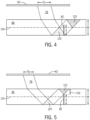
- FIGS. 4 and 5 illustrate how different effective transducer widths, s, result in differently sized coverage areas 120, 122.
- FIG. 4 is a schematic of one embodiment of the coverage areas for the transducer elements 62 having a first effective width, s 1 .
- the transducer elements 62 emit the ultrasonic signal 78 into the pipeline wall 80 having the thickness, w .
- Each of the coverage areas 120, 122 extends into the wall, past a center line 150, which represents a cylindrical plane extending axially through the middle of the pipeline wall 80.
- the coverage areas 120, 122 extend into the pipeline wall 80 substantially the same distance as the depth, d, of the feature 82.
- FIG. 5 is a schematic of one embodiment of the coverage areas for the transducer elements 62 having a second effective width, s 2 .
- the transducer elements 62 emit the ultrasonic signal 78 into the pipeline wall 80 having the thickness, w.
- Each of the coverage areas 120, 122 illustrated in FIG. 4 extends into the pipeline wall 80, but does not reach the center line 150.
- the coverage areas 120, 122 illustrated in FIG, 5 extend into the pipeline wall 80 substantially the same distance the remaining wall (i.e., the wall thickness, w, minus the feature depth, d ). Because each skid 60 includes an array of transducer elements 62 ( see FIG.
- the effective transducer width, s may be adjusted by utilizing various numbers (e.g., subsets) of the available transducer elements 62 within the array. For example, to achieve a desired effective transducer width, s, the system may utilize 8, 12, 16, 20, 24, 28, 32, or some other number, of the transducer elements 62 to emit the ultrasonic signal 78, where the number of transducer elements 62 utilized corresponds to the desired effective transducer width, s.
- the effective transducer width, s may be dynamically adjusted to effectuate adjustment of the coverage areas 120, 122.
- the pig 10 may move through the pipeline 12 utilizing a first number (e.g., first subset) of transducer elements 62 having an effective transducer width, s 1 , resulting in coverage areas 120, 122 that enable detection of features 82 having a depth, d, greater than a threshold value, d min .
- a customer may desire to know of features having a depth, d, greater than 7mm.
- the pig 10 may utilize the first subset of transducer elements 62 having the effective transducer width, s 1 , that detects the presence of features 82 having a depth, d, greater than 7mm. This amounts to a "coarse" shot.
- the processor 46 of the may analyze data in real time or near real time as the pig 10 moves through the pipeline 12. If the processor 46 of the control module 16 determines that a feature 82 having a depth, d, greater than the threshold value, d min , (e.g., 7mm) has been detected, the control module may change the number of transducer elements 62 utilized (e.g., second subset), adjusting the effective transducer width, s, to the second effective transducer width, s 2 , in order to determine the depth, d, of the feature 82. These supplemental shots amount to a "fine" shot.
- each skid 60 may be long compared to the width of each transducer element 62 and contain many transducer elements 62, the pig may be able to take a coarse shot of a section of pipe by emitting a first ultrasonic signal 78 ( see, e.g., FIG. 4 ) from a first subset of sensors 62, recognize the presence of a feature 82, then emit a second ultrasonic signal 78 ( see, e.g., FIG. 5 ) from a second subset of sensors 62 to determine the depth, d, of the feature 82. This may be done as the pig 10 moves continuously through the pipeline.
- each skid 60 may include an array of sensors 62 that may be 200 or more sensors 62 long.
- the first coarse shot ultrasonic signal 78 may be generated using the first subset of transducer elements 62 near a downstream end 28 of the skid 60, while the second fine shot ultrasonic signal 78 may be generated using a second subset of transducer elements 62 upstream from the first subset of transducer elements 62.
- Performing coarse shots until a feature 82 is recognized and then adding supplemental fine shots can reduce the amount of data produced and the processing power to process the collected data relative to a system that does only fine shots.
- only one additional fine shot may be performed to determine the depth, d, of the feature 82.
- multiple additional fine shots may be performed, fine tuning the effective transducer width, s, by adjusting the number of transducer elements 62 utilized, in order to determine the depth, d, of the feature 82.
- FIG. 6 is a graph 200 that illustrates a possibility for how to select the number of transducer elements 62 to be utilized for the fine shot discussed above.
- the horizontal axis 202 of graph 200 represents the remaining wall depth 152 and the vertical axis 204 of graph 200 represents the threshold amplitude, A T .
- the remaining wall depth 152 may be determined by subtracting the threshold feature depth, d min , which in some instances may be set by the customer or a user from the wall thickness, w, of the pipeline 12. For example, if a customer or user is interested in features 82 extending deeper than 3mm and the pipe wall thickness, w, is 7.3mm, then the remaining wall depth is 4.3mm.
- the wall thickness, w, of the pipeline 12 and the threshold feature depth, d min are substantially constant for a length of pipeline 12, these values may be determined before the pig 10 begins moving through the pipeline 12. Even in instances in which the wall thickness, w, changes between sections of pipeline across a run, these transitions in wall thickness may be accounted for ahead of time and the threshold feature depth, d min , may be determined before the pipeline pig 10 moves through the pipeline.
- the threshold amplitude, A T is the amplitude (e.g., in dB) above which a feature 82 is determined to exist.
- the threshold amplitude, A T may be determined experimentally based on a number of factors (e.g., pipe steel grade, medium, attenuation used). For example, the threshold amplitude, A T , may be determined experimentally and a lookup table created such that a user or the processor 46 may determine the threshold amplitude, A T , based on one or more known variables. Based on the remaining wall depth 152 and the threshold amplitude, A T , the number of transducer elements 62 for a fine shot may be determined.
- the appropriate number of transducer elements 62 for a fine shot may be 20 transducer elements (line 212), 28 transducer elements (line 214), 32 transducer elements (line 216), or some other number of transducer elements.
- graph 200 is merely an example and that similar graphs for determining the number of transducer elements to be utilized in a fine shot may vary from embodiment to embodiment.
- FIG. 7 is a flow chart of a process 300 for determining the depth of a feature 82 within a wall 80 of a section of pipeline 12.
- the remaining wall depth 152 may be determined based on the threshold feature depth, d min , set by a user or a customer and the wall thickness, w, of the pipeline. As previously discussed the remaining wall depth 152 may be determined before the pig 10 is moved through the pipeline 12.
- the amplitude threshold 306, A T may be determined and output.
- the amplitude threshold 306, A T may be determined by the processor 46 using a lookup table stored in memory 48 based on one or more variables.
- the pipeline pig 12 may be directed through the pipeline 12.
- the pig 10 may be propelled through a section of pipeline 12 by a difference between the pressure P1 ahead of the pig 10 and the pressure P2 behind the pig 10, as maintained by, for example, the plurality of sealing members 40.
- the pig 10 may pass through the section of pipeline 12 based upon the pressure of a fluid flowing through the pipeline 12 or based upon fluid pressure using a pump in an upstream direction 30 or downstream direction 28 of the pig 10.
- a coarse ultrasonic signal 78 is emitted from a first subset of transducer elements 62 selected by the processor 46. Echoes from the ultrasonic signal 78 propagating through the pipeline wall 80 and reflecting back toward the transducer elements 62 may be received and analyzed (e.g., by the processor 46 of the control module 16).
- the processor 46 of the control module 16 determines whether or not a feature 82 has been detected based on analysis of the collected data. If a feature 82 has not been detected, the processor may instruct the pig 10 to continue emitting coarse ultrasonic signals, as set forth on block 310. If a feature 82 has been detected, the pig 10 proceeds to block 314. At block 314, the processor 46 of the control module 16 determines the location of the feature 82.
- the processor 46 of the control module 16 determines a second subset of transducer elements 62 based on the remaining wall depth 152 and the amplitude threshold 306. For example, in some embodiments, the number of transducer elements 62 may be determined using a chart or a lookup table, as described with regard to FIG. 6 .
- a fine ultrasonic signal 78 is emitted from the second subset of transducer elements 62 at or near the feature 82 location determined in block 314. Echoes from the ultrasonic signal 78 propagating through the pipeline wall 80 and reflecting back toward the transducer elements 62 may be received and analyzed (e.g., by the processor 46 of the control module 16).
- the processor 46 of the control module 16 determines whether or not the feature 82 depth, d, can be determined based on the collected data. If the feature 82 depth, d, can be determined, the processor 46 of the control module 16 determines the feature depth, d, (block 322) and outputs the feature depth, d, 324. In some embodiments, the feature depth, d, 324 may be determined in post processing. If the processor 46 of the control module 16 determines that the feature depth, d, cannot be determined, the pig 10 proceeds to block 326 and adjusts the number of transducer elements 62 in the second subset of transducer elements 62.
- the pig 10 then proceeds to block 318 and emits another fine ultrasonic signal 78 from the adjusted second subset of transducer elements 62.
- additional data processing e.g., post-processing
- a user may utilize the computer 64 subsequent to a period of time passage, such as minutes, hours, days, weeks, or months after data has been collected to perform additional analysis of the collected data.
- the disclosed techniques may be used to determine the depth of features, and in some cases, deep features 82 within a wall 80 of a pipeline 12.
- a pipeline pig 10 having a plurality of skids 60, each equipped with an array of ultrasonic transducer elements 62, can proceed through a section of pipeline 12.
- the pipeline pig 10 can utilize a first subset of transducer elements 62 to emit a coarse ultrasonic signal 78 into the wall 80 of the pipeline 12.
- the pig 10 Based on echoes sensed from the ultrasonic signals propagating through and reflecting within the wall 80 of the pipeline 12, the pig 10 can detect features within the wall 80 of the pipeline 12.
- the pig 10 may then emit one or more fine ultrasonic signals 78 from a second subset of the ultrasonic transducer elements 62.
- a depth of the feature 82 may be determined. Using a coarse and a fine ultrasonic signal can prevent the system 10 from being overloaded with data and also can make efficient use of the available processing power on the pig 10, enabling real time, or near real time, data analysis. Once the depth of one or more features have been determined, determinations as to the condition of the pipeline 12 may be made. For features with a depth large enough to warrant repair, plans may be made regarding when and how to repair the feature.
- the subject matter described herein can be implemented in digital electronic circuitry, or in computer software, firmware, or hardware, including the structural means disclosed in this specification and structural equivalents thereof, or in combinations of them.
- the subject matter described herein can be implemented as one or more computer program products, such as one or more computer programs tangibly embodied in an information carrier (e.g., in a machine-readable storage device), or embodied in a propagated signal, for execution by, or to control the operation of, data processing apparatus (e.g., a programmable processor, a computer, or multiple computers).
- a computer program (also known as a program, software, software application, or code) can be written in any form of programming language, including compiled or interpreted languages, and it can be deployed in any form, including as a stand-alone program or as a module, component, subroutine, or other unit suitable for use in a computing environment.
- a computer program does not necessarily correspond to a file.
- a program can be stored in a portion of a file that holds other programs or data, in a single file dedicated to the program in question, or in multiple coordinated files (e.g., files that store one or more modules, sub-programs, or portions of code).
- a computer program can be deployed to be executed on one computer or on multiple computers at one site or distributed across multiple sites and interconnected by a communication network.
- processors suitable for the execution of a computer program include, by way of example, both general and special purpose microprocessors, and any one or more processor of any kind of digital computer.
- a processor will receive instructions and data from a read-only memory or a random access memory or both.
- the essential elements of a computer are a processor for executing instructions and one or more memory devices for storing instructions and data.
- a computer will also include, or be operatively coupled to receive data from or transfer data to, or both, one or more mass storage devices for storing data, e.g., magnetic, magneto-optical disks, or optical disks.
- Information carriers suitable for embodying computer program instructions and data include all forms of non-volatile memory, including by way of example semiconductor memory devices, (e.g., EPROM, EEPROM, and flash memory devices); magnetic disks, (e.g., internal hard disks or removable disks); magneto-optical disks; and optical disks (e.g., CD and DVD disks).
- semiconductor memory devices e.g., EPROM, EEPROM, and flash memory devices
- magnetic disks e.g., internal hard disks or removable disks
- magneto-optical disks e.g., CD and DVD disks
- optical disks e.g., CD and DVD disks.
- the processor and the memory can be supplemented by, or incorporated in, special purpose logic circuitry.
- the subject matter described herein can be implemented on a computer having a display device, e.g., a CRT (cathode ray tube) or LCD (liquid crystal display) monitor, for displaying information to the user and a keyboard and a pointing device, (e.g., a mouse or a trackball), by which the user can provide input to the computer.
- a display device e.g., a CRT (cathode ray tube) or LCD (liquid crystal display) monitor
- a keyboard and a pointing device e.g., a mouse or a trackball
- Other kinds of devices can be used to provide for interaction with a user as well.
- feedback provided to the user can be any form of sensory feedback, (e.g., visual feedback, auditory feedback, or tactile feedback), and input from the user can be received in any form, including acoustic, speech, or tactile input.
- modules refers to computing software, firmware, hardware, and/or various combinations thereof. At a minimum, however, modules are not to be interpreted as software that is not implemented on hardware, firmware, or recorded on a non-transitory processor readable recordable storage medium (i.e., modules are not software per se ). Indeed “module” is to be interpreted to always include at least some physical, non-transitory hardware such as a part of a processor or computer. Two different modules can share the same physical hardware (e.g., two different modules can use the same processor and network interface). The modules described herein can be combined, integrated, separated, and/or duplicated to support various applications.
- a function described herein as being performed at a particular module can be performed at one or more other modules and/or by one or more other devices instead of or in addition to the function performed at the particular module.
- the modules can be implemented across multiple devices and/or other components local or remote to one another. Additionally, the modules can be moved from one device and added to another device, and/or can be included in both devices.
- the subject matter described herein can be implemented in a computing system that includes a back-end component (e.g., a data server), a middleware component (e.g., an application server), or a front-end component (e.g., a client computer having a graphical user interface or a web browser through which a user can interact with an implementation of the subject matter described herein), or any combination of such back-end, middleware, and front-end components.
- the components of the system can be interconnected by any form or medium of digital data communication, e.g., a communication network. Examples of communication networks include a local area network ("LAN”) and a wide area network (“WAN”), e.g., the Internet.
- LAN local area network
- WAN wide area network
- Approximating language may be applied to modify any quantitative representation that could permissibly vary without resulting in a change in the basic function to which it is related. Accordingly, a value modified by a term or terms, such as “about” and “substantially,” are not to be limited to the precise value specified. In at least some instances, the approximating language may correspond to the precision of an instrument for measuring the value.
- range limitations may be combined and/or interchanged, such ranges are identified and include all the sub-ranges contained therein unless context or language indicates otherwise.
Landscapes
- Physics & Mathematics (AREA)
- General Physics & Mathematics (AREA)
- General Health & Medical Sciences (AREA)
- Chemical & Material Sciences (AREA)
- Analytical Chemistry (AREA)
- Biochemistry (AREA)
- Life Sciences & Earth Sciences (AREA)
- Health & Medical Sciences (AREA)
- Immunology (AREA)
- Pathology (AREA)
- Engineering & Computer Science (AREA)
- Signal Processing (AREA)
- Acoustics & Sound (AREA)
- Investigating Or Analyzing Materials By The Use Of Ultrasonic Waves (AREA)
- Length Measuring Devices Characterised By Use Of Acoustic Means (AREA)
Claims (12)
- Rohrleitungsinspektionssystem, umfassend:
einen Rohrleitungsmolch (10), umfassend:eine Vielzahl von Ultraschallwandlerelementen (62), die sich in einer Anordnung befinden, wobei jedes der Vielzahl von Ultraschallwandlerelementen (62) konfiguriert ist, um ein Ultraschallsignal in eine Wand (80) einer Rohrleitung (12) zu emittieren und Echos des Ultraschallsignals von der Rohrleitungswand (80) zu empfangen;gekennzeichnet durch:
eine Steuerung (46), die konfiguriert ist zum:Auswählen einer ersten Teilmenge der Vielzahl von Ultraschallwandlerelementen (62), von denen erste Ultraschallsignale in die Wand (80) der Rohrleitung (12) emittiert werden sollen, während der Rohrleitungsmolch (10) durch die Rohrleitung (12) passiert;Analysieren der Echos der ersten Ultraschallsignale, die durch die erste Teilmenge der Vielzahl von Ultraschallwandlerelementen (62) empfangen werden, um ein Merkmal (82) in der Rohrleitungswand (80) zu erfassen;Auswählen einer zweiten Teilmenge der Vielzahl von Ultraschallwandlerelementen (62), um zweite Ultraschallsignale in die Wand (80) der Rohrleitung (12) zu emittieren, während der Rohrleitungsmolch (10) durch die Rohrleitung (12) passiert, wenn das Merkmal (82) in der Rohrleitungswand (80) erfasst wird, wobei die zweite Teilmenge der Vielzahl von Ultraschallwandlerelementen (62) basierend auf einer verbleibenden Wandtiefe der Rohrleitungswand (80) und einem Schwellenwert einer Amplitude ausgewählt wird; undAnalysieren der Echos der zweiten Ultraschallsignale, die durch die zweite Teilmenge der Vielzahl von Ultraschallwandlerelementen (62) empfangen werden, um eine Tiefe des Merkmals (82) in der Rohrleitungswand zu bestimmen. - Rohrleitungsinspektionssystem nach Anspruch 1, wobei die Steuerung (46) konfiguriert ist, um die verbleibende Wandtiefe durch ein Subtrahieren einer Schwellenmerkmaltiefe von einer Dicke der Rohrleitungswand (80) zu bestimmen.
- Rohrleitungsinspektionssystem nach Anspruch 1, wobei die Steuerung (46) konfiguriert ist, um die Amplitudenschwelle basierend auf einer Nachschlagetabelle zu bestimmen.
- Rohrleitungsinspektionssystem nach Anspruch 1, wobei die Steuerung (46) konfiguriert ist, um eine Anzahl von Ultraschallwandlerelementen in der zweiten Teilmenge der Vielzahl von Ultraschallwandlerelementen (62) einzustellen, falls die Tiefe des Merkmals (82) nicht basierend auf den Echos des zweiten Ultraschallsignals bestimmt werden kann, das durch die zweite Teilmenge von Ultraschallwandlerelementen emittiert wird.
- Rohrleitungsinspektionssystem nach Anspruch 1, wobei der Rohrleitungsmolch (10) umfasst:ein Sensorträgermodul (18), umfassend die Vielzahl von Wandlerelementen (62); undein Steuermodul (16), umfassend die Steuerung (46), wobei das Sensorträgermodul (18) und das Steuermodul (16) durch eine Verknüpfung (20) miteinander gekoppelt sind.
- Rohrleitungsinspektionssystem nach Anspruch 5, wobei das Sensorträgermodul (18) eine Vielzahl von Kufen umfasst, die in Umfangsrichtung um das Sensorträgermodul (18) eingerichtet sind, wobei mindestens eine der Vielzahl von Kufen die Anordnung von Ultraschallwandlerelementen (62) umfasst.
- Rohrleitungsinspektionssystem nach Anspruch 1, umfassend eine Rechenvorrichtung zum Nachverarbeiten von Daten, die durch den Rohrleitungsmolch (10) gesammelt werden.
- Verfahren, umfassend:Leiten einer Vielzahl von Ultraschallwandlerelementen (62), die sich in einer Anordnung befinden, entlang einer Wand (80) einer Rohrleitung (12);Emittieren eines ersten Ultraschallsignals von einer ersten Teilmenge der Vielzahl von Ultraschallwandlerelementen (62);Empfangen von Echos des ersten Ultraschallsignals von der Rohrleitungswand (80); undAnalysieren der Echos des ersten Ultraschallsignals, um ein Merkmal (82) in der Rohrleitungswand (80) zu erfassen;gekennzeichnet durch:Auswählen einer zweiten Teilmenge der Vielzahl von Ultraschallwandlerelementen (62), wenn das Merkmal (82) in der Rohrleitungswand (80) erfasst wird, wobei die zweite Teilmenge der Vielzahl von Ultraschallwandlerelementen (62) basierend auf einer verbleibenden Wandtiefe und einer Amplitudenschwelle ausgewählt wird;Emittieren eines zweiten Ultraschallsignals von einer zweiten Teilmenge der Vielzahl von Ultraschallwandlerelementen (62); undAnalysieren der Echos des zweiten Ultraschallsignals, um eine Tiefe des Merkmals (82) in der Rohrleitungswand (80) zu bestimmen.
- Verfahren nach Anspruch 10, wobei die erste Teilmenge der Vielzahl von Ultraschallwandlerelementen (62) eine größere Anzahl von Ultraschallwandlerelementen relativ zu der zweiten Teilmenge der Vielzahl von Ultraschallwandlerelementen (62) umfasst.
- Verfahren nach Anspruch 8, wobei die verbleibende Wandtiefe durch ein Subtrahieren einer Schwellenmerkmaltiefe von einer Dicke der Rohrleitungswand (80) bestimmt wird und wobei die Amplitudenschwelle basierend auf einer Nachschlagetabelle bestimmt wird.
- Verfahren nach Anspruch 8, umfassend das Emittieren eines dritten Ultraschallsignals von einer dritten Teilmenge der Vielzahl von Ultraschallwandlerelementen (62), wenn die Tiefe des Merkmals (82) in der Rohrleitungswand (80) nicht basierend auf den Echos des zweiten Ultraschallsignals bestimmt werden kann.
- Nichtflüchtiges computerlesbares Medium, umfassend ausführbare Anweisungen, die, wenn sie ausgeführt werden, einen Prozessor veranlassen zum:Auswählen einer ersten Teilmenge einer Vielzahl von Ultraschallwandlerelementen (62), die sich in einer Anordnung befinden, wobei die erste Teilmenge der Vielzahl von Ultraschallwandlerelementen (62) konfiguriert ist, um ein erstes Ultraschallsignal in eine Wand (80) einer Rohrleitung (12) zu emittieren und Echos des ersten Ultraschallsignals von der Rohrleitungswand (80) zu empfangen;Analysieren der Echos des ersten Ultraschallsignals, das durch die erste Teilmenge der Vielzahl von Ultraschallwandlerelementen (62) empfangen wird, um ein Merkmal (82) in der Rohrleitungswand (80) zu erfassen;Auswählen einer zweiten Teilmenge der Vielzahl von Ultraschallwandlerelementen (62), wenn das Merkmal (82) in der Rohrleitungswand (80) erfasst wird, wobei die zweite Teilmenge der Vielzahl von Ultraschallwandlerelementen (62) basierend auf einer verbleibenden Wandtiefe und einer Amplitudenschwelle ausgewählt wird, und wobei die zweite Teilmenge der Vielzahl von Ultraschallwandlerelementen (62) konfiguriert ist, um ein zweites Ultraschallsignal in die Wand (80) der Rohrleitung (12) zu emittieren und Echos des zweiten Ultraschallsignals von der Rohrleitungswand (80) zu empfangen; undAnalysieren der Echos des zweiten Ultraschallsignals, um eine Tiefe des Merkmals (82) in der Rohrleitungswand (80) zu bestimmen.
Applications Claiming Priority (2)
| Application Number | Priority Date | Filing Date | Title |
|---|---|---|---|
| US15/617,632 US10429176B2 (en) | 2017-06-08 | 2017-06-08 | Pipeline deep crack detection |
| PCT/US2018/027464 WO2018226314A1 (en) | 2017-06-08 | 2018-04-13 | Pipeline deep crack detection |
Publications (3)
| Publication Number | Publication Date |
|---|---|
| EP3635359A1 EP3635359A1 (de) | 2020-04-15 |
| EP3635359A4 EP3635359A4 (de) | 2021-03-03 |
| EP3635359B1 true EP3635359B1 (de) | 2023-10-04 |
Family
ID=64562203
Family Applications (1)
| Application Number | Title | Priority Date | Filing Date |
|---|---|---|---|
| EP18813942.2A Active EP3635359B1 (de) | 2017-06-08 | 2018-04-13 | System, verfahren und computerprogramm zur erkennung tiefer risse in rohrleitungen |
Country Status (7)
| Country | Link |
|---|---|
| US (2) | US10429176B2 (de) |
| EP (1) | EP3635359B1 (de) |
| CN (1) | CN110651174B (de) |
| AU (1) | AU2018281813B2 (de) |
| CA (1) | CA3066058C (de) |
| SA (1) | SA519410736B1 (de) |
| WO (1) | WO2018226314A1 (de) |
Families Citing this family (11)
| Publication number | Priority date | Publication date | Assignee | Title |
|---|---|---|---|---|
| AU2011329288B2 (en) * | 2010-11-15 | 2016-06-02 | Parker-Hannifin Corporation | Embedded or clip-on device for health monitoring of an article |
| US10060883B2 (en) * | 2015-10-01 | 2018-08-28 | General Electric Company | Pipeline crack detection |
| US11959739B2 (en) * | 2019-08-22 | 2024-04-16 | Baker Hughes Oilfield Operations Llc | Assisted corrosion and erosion recognition |
| GB2587816B (en) * | 2019-10-03 | 2022-03-30 | Darkvision Tech | Intelligent localized high-resolution imaging of tubulars |
| CN111579646B (zh) * | 2020-05-29 | 2021-07-06 | 中国地质大学(北京) | 石质文物裂隙的原位、无损检测方法 |
| CN113029466A (zh) * | 2021-03-05 | 2021-06-25 | 师大瑞利光电科技(清远)有限公司 | 一种气密性设备的检测方法、装置以及电子设备 |
| WO2023108289A1 (en) * | 2021-12-15 | 2023-06-22 | Pure Technologies Ltd. | Apparatus, systems and methods for pipeline condition assessment |
| CN114910006B (zh) * | 2022-07-15 | 2022-09-30 | 天津市特种设备监督检验技术研究院(天津市特种设备事故应急调查处理中心) | 一种管道缺陷长度检验装置及检验方法 |
| US20240329006A1 (en) * | 2023-03-30 | 2024-10-03 | Daniel R. Tieger | Pipeline monitoring apparatus and method of use thereof |
| CN116412363B (zh) * | 2023-04-13 | 2026-04-28 | 中国石油天然气股份有限公司 | 一种超声波检测定位装置和方法 |
| GB2638386A (en) * | 2024-01-19 | 2025-08-27 | Cokebusters Ltd | Pig for inspecting a tubular object |
Family Cites Families (35)
| Publication number | Priority date | Publication date | Assignee | Title |
|---|---|---|---|---|
| US36680A (en) * | 1862-10-14 | Improvement in lamps | ||
| LU32674A1 (fr) | 1953-03-06 | Acec | Dispositif de contrôle au moyen d'ultra-sons | |
| CH594848A5 (de) | 1976-02-24 | 1978-01-31 | Sigel Gfeller Alwin | |
| NL8020337A (nl) | 1980-03-03 | 1982-01-04 | Republic Steel Corp | Supersone keuring. |
| CA1169541A (en) | 1980-03-03 | 1984-06-19 | James M. Toth | Ultrasonic flaw detector having a transducer with an involute-like transmitting surface |
| DE3312958A1 (de) | 1983-04-11 | 1984-10-11 | Industrietechnik Kalenborn Gmbh, 5461 Kalenborn | Rohrreinigungsgeraet |
| CA2162424C (en) | 1995-11-08 | 2006-01-24 | Brian Varney | Speed controlled pig |
| CA2284641A1 (en) | 1997-03-24 | 1998-10-01 | Bj Services Company | Inspection with global positioning and inertial navigation |
| US6578422B2 (en) | 2001-08-14 | 2003-06-17 | Varco I/P, Inc. | Ultrasonic detection of flaws in tubular members |
| RU2212660C1 (ru) | 2001-12-25 | 2003-09-20 | ЗАО "Нефтегазкомплектсервис" | Способ внутритрубного ультразвукового контроля |
| DE10202432A1 (de) | 2002-01-22 | 2003-08-07 | Pii Pipetronix Gmbh | Verfahren und Vorrichtung zum Untersuchen von Rohrleitungen |
| US6745136B2 (en) | 2002-07-02 | 2004-06-01 | Varco I/P, Inc. | Pipe inspection systems and methods |
| DE10259218A1 (de) | 2002-12-17 | 2004-07-01 | Agfa Ndt Gmbh | Verfahren und Vorrichtung zur Größenbestimmung eines Risses in einem Werkstück mittels der Ultraschall-Impuls-Methode |
| NL1023265C2 (nl) | 2003-04-25 | 2004-10-27 | Roentgen Tech Dienst Bv | Ultrasoon onderzoeksysteem. |
| US7299697B2 (en) | 2005-03-31 | 2007-11-27 | General Electric Company | Method and system for inspecting objects using ultrasound scan data |
| FR2888327B1 (fr) | 2005-07-05 | 2008-07-04 | Saipem S A Sa | Procede et dispositif de controle de soudure de raccordement de conduite par sonde a ultrasons |
| US20070023096A1 (en) | 2005-07-29 | 2007-02-01 | Tdw Delaware, Inc. | Isolation tool for plugging the interior of a pipeline |
| GB2437547B (en) | 2006-04-28 | 2010-07-14 | Genesis Oil And Gas Consultant | Method and apparatus for inspecting pipes |
| NL1032186C2 (nl) | 2006-07-17 | 2008-01-18 | Roentgen Tech Dienst Bv | Systeem voor het meten aan een wand van een pijpleiding met phased array. |
| WO2009038456A1 (en) | 2007-09-18 | 2009-03-26 | Röntgen Technische Dienst B.V. | Inspection device and method for inspection |
| US7963165B2 (en) | 2007-09-25 | 2011-06-21 | Los Alamos National Security, Llc | Non-contact feature detection using ultrasonic Lamb waves |
| US7997139B2 (en) | 2007-12-03 | 2011-08-16 | Fbs, Inc. | Guided wave pipeline inspection system and method with enhanced natural focusing techniques |
| EP2105737A1 (de) | 2008-03-25 | 2009-09-30 | Nederlandse Organisatie voor toegepast-natuurwetenschappelijk Onderzoek TNO | System zur Entdeckung von Defekten in einer Röhrenwand mittels Ultraschall |
| GB0903232D0 (en) * | 2009-02-25 | 2009-04-08 | Saipem Spa | A method for testing pipeline welds |
| US8346985B2 (en) * | 2009-07-27 | 2013-01-01 | Logitech Europe S.A. | Receiver configured to pair to multiple wireless devices |
| US8390278B2 (en) | 2009-10-20 | 2013-03-05 | Westinghouse Electric Company Llc | Eddy current inspection probe for inspecting the interior of a tubular member |
| EP2527707A1 (de) * | 2011-05-26 | 2012-11-28 | Pii Limited | Vorrichtung zur Leitungsprüfung |
| EP2597445A1 (de) * | 2011-11-22 | 2013-05-29 | Pii Limited | Verfahren zur Leitungsprüfung |
| CA2875532A1 (en) | 2012-06-07 | 2013-12-12 | California Institute Of Technology | Communication in pipes using acoustic modems that provide minimal obstruction to fluid flow |
| JP5884993B2 (ja) * | 2013-09-12 | 2016-03-15 | 横河電機株式会社 | 超音波配管測定装置 |
| WO2015160340A1 (en) | 2014-04-16 | 2015-10-22 | Halliburton Energy Services, Inc. | Ultrasonic signal time-frequency decomposition for borehole evaluation or pipeline inspection |
| NO346618B1 (en) | 2015-02-24 | 2022-10-31 | Halfwave As | An apparatus and method for inspecting a pipeline |
| US10036680B2 (en) * | 2015-03-19 | 2018-07-31 | General Electric Company | Pipeline sensor carrier |
| CN104792868A (zh) * | 2015-04-10 | 2015-07-22 | 吴从兵 | 一种回旋式扫描筒体超声在线检测方法 |
| US10060883B2 (en) | 2015-10-01 | 2018-08-28 | General Electric Company | Pipeline crack detection |
-
2017
- 2017-06-08 US US15/617,632 patent/US10429176B2/en active Active
-
2018
- 2018-04-13 WO PCT/US2018/027464 patent/WO2018226314A1/en not_active Ceased
- 2018-04-13 EP EP18813942.2A patent/EP3635359B1/de active Active
- 2018-04-13 CA CA3066058A patent/CA3066058C/en active Active
- 2018-04-13 AU AU2018281813A patent/AU2018281813B2/en active Active
- 2018-04-13 CN CN201880032754.1A patent/CN110651174B/zh active Active
-
2019
- 2019-09-27 US US16/586,023 patent/US10801837B2/en active Active
- 2019-12-05 SA SA519410736A patent/SA519410736B1/ar unknown
Also Published As
| Publication number | Publication date |
|---|---|
| EP3635359A1 (de) | 2020-04-15 |
| WO2018226314A1 (en) | 2018-12-13 |
| SA519410736B1 (ar) | 2022-08-16 |
| US10801837B2 (en) | 2020-10-13 |
| US20180356371A1 (en) | 2018-12-13 |
| US20200132449A1 (en) | 2020-04-30 |
| EP3635359A4 (de) | 2021-03-03 |
| AU2018281813B2 (en) | 2020-10-22 |
| CA3066058C (en) | 2020-11-24 |
| CA3066058A1 (en) | 2018-12-13 |
| AU2018281813A1 (en) | 2020-01-30 |
| CN110651174B (zh) | 2021-08-17 |
| CN110651174A (zh) | 2020-01-03 |
| US10429176B2 (en) | 2019-10-01 |
Similar Documents
| Publication | Publication Date | Title |
|---|---|---|
| US10801837B2 (en) | Pipeline deep crack detection | |
| US10557831B2 (en) | Pipeline crack detection | |
| US9672187B2 (en) | System and method for directing guided waves through structures | |
| CN100554874C (zh) | 利用超声扫描数据检查对象的方法和系统 | |
| US11874255B2 (en) | Dynamic adjustment of phased array parameters for ultrasonic inspection | |
| US9207213B2 (en) | Method and apparatus for inspecting and monitoring pipe | |
| US10527590B2 (en) | Apparatus and method for inspecting a pipeline | |
| EP4433814A1 (de) | Anzeigeeinstellung bei der visuellen darstellung von ultraschallmessungen | |
| JP6953953B2 (ja) | 斜角超音波探傷の健全性評価方法、及びこれを用いた斜角超音波探傷方法 | |
| RU2607258C1 (ru) | Способ внутритрубного ультразвукового контроля | |
| JP2014109551A (ja) | 流体識別装置及び流体識別方法 | |
| US20240319140A1 (en) | Transmission angle calibration | |
| RU2690975C1 (ru) | Способ определения сигнала от стенки трубы по данным ВИП CD статистики энергетических линий | |
| US11579120B2 (en) | Colored defect detection curves | |
| Bloom et al. | Opportunities for permanent corrosion monitoring of pipelines using guided wave tomography | |
| Horne et al. | Detection and measurement of pitting corrosion using short range guided wave scanning | |
| UA61587A (en) | Method for the ultrasonic monitoring of geometrical characteristics of pipes |
Legal Events
| Date | Code | Title | Description |
|---|---|---|---|
| STAA | Information on the status of an ep patent application or granted ep patent |
Free format text: STATUS: THE INTERNATIONAL PUBLICATION HAS BEEN MADE |
|
| PUAI | Public reference made under article 153(3) epc to a published international application that has entered the european phase |
Free format text: ORIGINAL CODE: 0009012 |
|
| STAA | Information on the status of an ep patent application or granted ep patent |
Free format text: STATUS: REQUEST FOR EXAMINATION WAS MADE |
|
| 17P | Request for examination filed |
Effective date: 20200107 |
|
| AK | Designated contracting states |
Kind code of ref document: A1 Designated state(s): AL AT BE BG CH CY CZ DE DK EE ES FI FR GB GR HR HU IE IS IT LI LT LU LV MC MK MT NL NO PL PT RO RS SE SI SK SM TR |
|
| AX | Request for extension of the european patent |
Extension state: BA ME |
|
| DAV | Request for validation of the european patent (deleted) | ||
| DAX | Request for extension of the european patent (deleted) | ||
| A4 | Supplementary search report drawn up and despatched |
Effective date: 20210202 |
|
| RIC1 | Information provided on ipc code assigned before grant |
Ipc: G01M 3/24 20060101AFI20210127BHEP |
|
| STAA | Information on the status of an ep patent application or granted ep patent |
Free format text: STATUS: EXAMINATION IS IN PROGRESS |
|
| 17Q | First examination report despatched |
Effective date: 20220825 |
|
| RAP1 | Party data changed (applicant data changed or rights of an application transferred) |
Owner name: BAKER HUGHES HOLDINGS LLC |
|
| P01 | Opt-out of the competence of the unified patent court (upc) registered |
Effective date: 20230526 |
|
| REG | Reference to a national code |
Ref country code: DE Ref legal event code: R079 Free format text: PREVIOUS MAIN CLASS: G01M0003240000 Ipc: G01B0017020000 Ref document number: 602018058783 Country of ref document: DE |
|
| GRAP | Despatch of communication of intention to grant a patent |
Free format text: ORIGINAL CODE: EPIDOSNIGR1 |
|
| STAA | Information on the status of an ep patent application or granted ep patent |
Free format text: STATUS: GRANT OF PATENT IS INTENDED |
|
| RIC1 | Information provided on ipc code assigned before grant |
Ipc: F16L 55/38 20060101ALN20230712BHEP Ipc: G01N 29/48 20060101ALI20230712BHEP Ipc: G01N 29/44 20060101ALI20230712BHEP Ipc: G01N 29/26 20060101ALI20230712BHEP Ipc: G01N 29/22 20060101ALI20230712BHEP Ipc: G01N 29/04 20060101ALI20230712BHEP Ipc: G01B 17/02 20060101AFI20230712BHEP |
|
| INTG | Intention to grant announced |
Effective date: 20230724 |
|
| GRAS | Grant fee paid |
Free format text: ORIGINAL CODE: EPIDOSNIGR3 |
|
| GRAA | (expected) grant |
Free format text: ORIGINAL CODE: 0009210 |
|
| STAA | Information on the status of an ep patent application or granted ep patent |
Free format text: STATUS: THE PATENT HAS BEEN GRANTED |
|
| AK | Designated contracting states |
Kind code of ref document: B1 Designated state(s): AL AT BE BG CH CY CZ DE DK EE ES FI FR GB GR HR HU IE IS IT LI LT LU LV MC MK MT NL NO PL PT RO RS SE SI SK SM TR |
|
| REG | Reference to a national code |
Ref country code: GB Ref legal event code: FG4D |
|
| REG | Reference to a national code |
Ref country code: CH Ref legal event code: EP |
|
| REG | Reference to a national code |
Ref country code: DE Ref legal event code: R096 Ref document number: 602018058783 Country of ref document: DE |
|
| REG | Reference to a national code |
Ref country code: IE Ref legal event code: FG4D |
|
| REG | Reference to a national code |
Ref country code: LT Ref legal event code: MG9D |
|
| REG | Reference to a national code |
Ref country code: NL Ref legal event code: MP Effective date: 20231004 |
|
| REG | Reference to a national code |
Ref country code: AT Ref legal event code: MK05 Ref document number: 1618148 Country of ref document: AT Kind code of ref document: T Effective date: 20231004 |
|
| PG25 | Lapsed in a contracting state [announced via postgrant information from national office to epo] |
Ref country code: NL Free format text: LAPSE BECAUSE OF FAILURE TO SUBMIT A TRANSLATION OF THE DESCRIPTION OR TO PAY THE FEE WITHIN THE PRESCRIBED TIME-LIMIT Effective date: 20231004 |
|
| PG25 | Lapsed in a contracting state [announced via postgrant information from national office to epo] |
Ref country code: GR Free format text: LAPSE BECAUSE OF FAILURE TO SUBMIT A TRANSLATION OF THE DESCRIPTION OR TO PAY THE FEE WITHIN THE PRESCRIBED TIME-LIMIT Effective date: 20240105 |
|
| PG25 | Lapsed in a contracting state [announced via postgrant information from national office to epo] |
Ref country code: IS Free format text: LAPSE BECAUSE OF FAILURE TO SUBMIT A TRANSLATION OF THE DESCRIPTION OR TO PAY THE FEE WITHIN THE PRESCRIBED TIME-LIMIT Effective date: 20240204 |
|
| PG25 | Lapsed in a contracting state [announced via postgrant information from national office to epo] |
Ref country code: LT Free format text: LAPSE BECAUSE OF FAILURE TO SUBMIT A TRANSLATION OF THE DESCRIPTION OR TO PAY THE FEE WITHIN THE PRESCRIBED TIME-LIMIT Effective date: 20231004 |
|
| PG25 | Lapsed in a contracting state [announced via postgrant information from national office to epo] |
Ref country code: AT Free format text: LAPSE BECAUSE OF FAILURE TO SUBMIT A TRANSLATION OF THE DESCRIPTION OR TO PAY THE FEE WITHIN THE PRESCRIBED TIME-LIMIT Effective date: 20231004 |
|
| PG25 | Lapsed in a contracting state [announced via postgrant information from national office to epo] |
Ref country code: ES Free format text: LAPSE BECAUSE OF FAILURE TO SUBMIT A TRANSLATION OF THE DESCRIPTION OR TO PAY THE FEE WITHIN THE PRESCRIBED TIME-LIMIT Effective date: 20231004 |
|
| PG25 | Lapsed in a contracting state [announced via postgrant information from national office to epo] |
Ref country code: LT Free format text: LAPSE BECAUSE OF FAILURE TO SUBMIT A TRANSLATION OF THE DESCRIPTION OR TO PAY THE FEE WITHIN THE PRESCRIBED TIME-LIMIT Effective date: 20231004 Ref country code: IS Free format text: LAPSE BECAUSE OF FAILURE TO SUBMIT A TRANSLATION OF THE DESCRIPTION OR TO PAY THE FEE WITHIN THE PRESCRIBED TIME-LIMIT Effective date: 20240204 Ref country code: GR Free format text: LAPSE BECAUSE OF FAILURE TO SUBMIT A TRANSLATION OF THE DESCRIPTION OR TO PAY THE FEE WITHIN THE PRESCRIBED TIME-LIMIT Effective date: 20240105 Ref country code: ES Free format text: LAPSE BECAUSE OF FAILURE TO SUBMIT A TRANSLATION OF THE DESCRIPTION OR TO PAY THE FEE WITHIN THE PRESCRIBED TIME-LIMIT Effective date: 20231004 Ref country code: BG Free format text: LAPSE BECAUSE OF FAILURE TO SUBMIT A TRANSLATION OF THE DESCRIPTION OR TO PAY THE FEE WITHIN THE PRESCRIBED TIME-LIMIT Effective date: 20240104 Ref country code: AT Free format text: LAPSE BECAUSE OF FAILURE TO SUBMIT A TRANSLATION OF THE DESCRIPTION OR TO PAY THE FEE WITHIN THE PRESCRIBED TIME-LIMIT Effective date: 20231004 Ref country code: PT Free format text: LAPSE BECAUSE OF FAILURE TO SUBMIT A TRANSLATION OF THE DESCRIPTION OR TO PAY THE FEE WITHIN THE PRESCRIBED TIME-LIMIT Effective date: 20240205 |
|
| PG25 | Lapsed in a contracting state [announced via postgrant information from national office to epo] |
Ref country code: SE Free format text: LAPSE BECAUSE OF FAILURE TO SUBMIT A TRANSLATION OF THE DESCRIPTION OR TO PAY THE FEE WITHIN THE PRESCRIBED TIME-LIMIT Effective date: 20231004 Ref country code: RS Free format text: LAPSE BECAUSE OF FAILURE TO SUBMIT A TRANSLATION OF THE DESCRIPTION OR TO PAY THE FEE WITHIN THE PRESCRIBED TIME-LIMIT Effective date: 20231004 Ref country code: PL Free format text: LAPSE BECAUSE OF FAILURE TO SUBMIT A TRANSLATION OF THE DESCRIPTION OR TO PAY THE FEE WITHIN THE PRESCRIBED TIME-LIMIT Effective date: 20231004 Ref country code: NO Free format text: LAPSE BECAUSE OF FAILURE TO SUBMIT A TRANSLATION OF THE DESCRIPTION OR TO PAY THE FEE WITHIN THE PRESCRIBED TIME-LIMIT Effective date: 20240104 Ref country code: LV Free format text: LAPSE BECAUSE OF FAILURE TO SUBMIT A TRANSLATION OF THE DESCRIPTION OR TO PAY THE FEE WITHIN THE PRESCRIBED TIME-LIMIT Effective date: 20231004 Ref country code: HR Free format text: LAPSE BECAUSE OF FAILURE TO SUBMIT A TRANSLATION OF THE DESCRIPTION OR TO PAY THE FEE WITHIN THE PRESCRIBED TIME-LIMIT Effective date: 20231004 |
|
| REG | Reference to a national code |
Ref country code: DE Ref legal event code: R097 Ref document number: 602018058783 Country of ref document: DE |
|
| PG25 | Lapsed in a contracting state [announced via postgrant information from national office to epo] |
Ref country code: DK Free format text: LAPSE BECAUSE OF FAILURE TO SUBMIT A TRANSLATION OF THE DESCRIPTION OR TO PAY THE FEE WITHIN THE PRESCRIBED TIME-LIMIT Effective date: 20231004 |
|
| PG25 | Lapsed in a contracting state [announced via postgrant information from national office to epo] |
Ref country code: CZ Free format text: LAPSE BECAUSE OF FAILURE TO SUBMIT A TRANSLATION OF THE DESCRIPTION OR TO PAY THE FEE WITHIN THE PRESCRIBED TIME-LIMIT Effective date: 20231004 |
|
| PG25 | Lapsed in a contracting state [announced via postgrant information from national office to epo] |
Ref country code: SK Free format text: LAPSE BECAUSE OF FAILURE TO SUBMIT A TRANSLATION OF THE DESCRIPTION OR TO PAY THE FEE WITHIN THE PRESCRIBED TIME-LIMIT Effective date: 20231004 |
|
| PG25 | Lapsed in a contracting state [announced via postgrant information from national office to epo] |
Ref country code: SM Free format text: LAPSE BECAUSE OF FAILURE TO SUBMIT A TRANSLATION OF THE DESCRIPTION OR TO PAY THE FEE WITHIN THE PRESCRIBED TIME-LIMIT Effective date: 20231004 Ref country code: SK Free format text: LAPSE BECAUSE OF FAILURE TO SUBMIT A TRANSLATION OF THE DESCRIPTION OR TO PAY THE FEE WITHIN THE PRESCRIBED TIME-LIMIT Effective date: 20231004 Ref country code: RO Free format text: LAPSE BECAUSE OF FAILURE TO SUBMIT A TRANSLATION OF THE DESCRIPTION OR TO PAY THE FEE WITHIN THE PRESCRIBED TIME-LIMIT Effective date: 20231004 Ref country code: IT Free format text: LAPSE BECAUSE OF FAILURE TO SUBMIT A TRANSLATION OF THE DESCRIPTION OR TO PAY THE FEE WITHIN THE PRESCRIBED TIME-LIMIT Effective date: 20231004 Ref country code: EE Free format text: LAPSE BECAUSE OF FAILURE TO SUBMIT A TRANSLATION OF THE DESCRIPTION OR TO PAY THE FEE WITHIN THE PRESCRIBED TIME-LIMIT Effective date: 20231004 Ref country code: DK Free format text: LAPSE BECAUSE OF FAILURE TO SUBMIT A TRANSLATION OF THE DESCRIPTION OR TO PAY THE FEE WITHIN THE PRESCRIBED TIME-LIMIT Effective date: 20231004 Ref country code: CZ Free format text: LAPSE BECAUSE OF FAILURE TO SUBMIT A TRANSLATION OF THE DESCRIPTION OR TO PAY THE FEE WITHIN THE PRESCRIBED TIME-LIMIT Effective date: 20231004 |
|
| PLBE | No opposition filed within time limit |
Free format text: ORIGINAL CODE: 0009261 |
|
| STAA | Information on the status of an ep patent application or granted ep patent |
Free format text: STATUS: NO OPPOSITION FILED WITHIN TIME LIMIT |
|
| 26N | No opposition filed |
Effective date: 20240705 |
|
| PG25 | Lapsed in a contracting state [announced via postgrant information from national office to epo] |
Ref country code: SI Free format text: LAPSE BECAUSE OF FAILURE TO SUBMIT A TRANSLATION OF THE DESCRIPTION OR TO PAY THE FEE WITHIN THE PRESCRIBED TIME-LIMIT Effective date: 20231004 |
|
| PG25 | Lapsed in a contracting state [announced via postgrant information from national office to epo] |
Ref country code: SI Free format text: LAPSE BECAUSE OF FAILURE TO SUBMIT A TRANSLATION OF THE DESCRIPTION OR TO PAY THE FEE WITHIN THE PRESCRIBED TIME-LIMIT Effective date: 20231004 |
|
| REG | Reference to a national code |
Ref country code: DE Ref legal event code: R119 Ref document number: 602018058783 Country of ref document: DE |
|
| PG25 | Lapsed in a contracting state [announced via postgrant information from national office to epo] |
Ref country code: MC Free format text: LAPSE BECAUSE OF FAILURE TO SUBMIT A TRANSLATION OF THE DESCRIPTION OR TO PAY THE FEE WITHIN THE PRESCRIBED TIME-LIMIT Effective date: 20231004 |
|
| PG25 | Lapsed in a contracting state [announced via postgrant information from national office to epo] |
Ref country code: MC Free format text: LAPSE BECAUSE OF FAILURE TO SUBMIT A TRANSLATION OF THE DESCRIPTION OR TO PAY THE FEE WITHIN THE PRESCRIBED TIME-LIMIT Effective date: 20231004 |
|
| REG | Reference to a national code |
Ref country code: CH Ref legal event code: PL |
|
| PG25 | Lapsed in a contracting state [announced via postgrant information from national office to epo] |
Ref country code: LU Free format text: LAPSE BECAUSE OF NON-PAYMENT OF DUE FEES Effective date: 20240413 |
|
| GBPC | Gb: european patent ceased through non-payment of renewal fee |
Effective date: 20240413 |
|
| REG | Reference to a national code |
Ref country code: BE Ref legal event code: MM Effective date: 20240430 |
|
| PG25 | Lapsed in a contracting state [announced via postgrant information from national office to epo] |
Ref country code: LU Free format text: LAPSE BECAUSE OF NON-PAYMENT OF DUE FEES Effective date: 20240413 |
|
| PG25 | Lapsed in a contracting state [announced via postgrant information from national office to epo] |
Ref country code: DE Free format text: LAPSE BECAUSE OF NON-PAYMENT OF DUE FEES Effective date: 20241105 |
|
| PG25 | Lapsed in a contracting state [announced via postgrant information from national office to epo] |
Ref country code: BE Free format text: LAPSE BECAUSE OF NON-PAYMENT OF DUE FEES Effective date: 20240430 |
|
| PG25 | Lapsed in a contracting state [announced via postgrant information from national office to epo] |
Ref country code: GB Free format text: LAPSE BECAUSE OF NON-PAYMENT OF DUE FEES Effective date: 20240413 |
|
| PG25 | Lapsed in a contracting state [announced via postgrant information from national office to epo] |
Ref country code: FR Free format text: LAPSE BECAUSE OF NON-PAYMENT OF DUE FEES Effective date: 20240430 |
|
| PG25 | Lapsed in a contracting state [announced via postgrant information from national office to epo] |
Ref country code: GB Free format text: LAPSE BECAUSE OF NON-PAYMENT OF DUE FEES Effective date: 20240413 Ref country code: FR Free format text: LAPSE BECAUSE OF NON-PAYMENT OF DUE FEES Effective date: 20240430 Ref country code: DE Free format text: LAPSE BECAUSE OF NON-PAYMENT OF DUE FEES Effective date: 20241105 Ref country code: BE Free format text: LAPSE BECAUSE OF NON-PAYMENT OF DUE FEES Effective date: 20240430 Ref country code: CH Free format text: LAPSE BECAUSE OF NON-PAYMENT OF DUE FEES Effective date: 20240430 |
|
| PG25 | Lapsed in a contracting state [announced via postgrant information from national office to epo] |
Ref country code: IE Free format text: LAPSE BECAUSE OF NON-PAYMENT OF DUE FEES Effective date: 20240413 |
|
| PG25 | Lapsed in a contracting state [announced via postgrant information from national office to epo] |
Ref country code: CY Free format text: LAPSE BECAUSE OF FAILURE TO SUBMIT A TRANSLATION OF THE DESCRIPTION OR TO PAY THE FEE WITHIN THE PRESCRIBED TIME-LIMIT; INVALID AB INITIO Effective date: 20180413 |
|
| PG25 | Lapsed in a contracting state [announced via postgrant information from national office to epo] |
Ref country code: HU Free format text: LAPSE BECAUSE OF FAILURE TO SUBMIT A TRANSLATION OF THE DESCRIPTION OR TO PAY THE FEE WITHIN THE PRESCRIBED TIME-LIMIT; INVALID AB INITIO Effective date: 20180413 |
|
| PG25 | Lapsed in a contracting state [announced via postgrant information from national office to epo] |
Ref country code: FI Free format text: LAPSE BECAUSE OF FAILURE TO SUBMIT A TRANSLATION OF THE DESCRIPTION OR TO PAY THE FEE WITHIN THE PRESCRIBED TIME-LIMIT Effective date: 20231004 |