EP3635285B1 - Ending for a hose, mainly as connecting element - Google Patents
Ending for a hose, mainly as connecting element Download PDFInfo
- Publication number
- EP3635285B1 EP3635285B1 EP18746748.5A EP18746748A EP3635285B1 EP 3635285 B1 EP3635285 B1 EP 3635285B1 EP 18746748 A EP18746748 A EP 18746748A EP 3635285 B1 EP3635285 B1 EP 3635285B1
- Authority
- EP
- European Patent Office
- Prior art keywords
- mouthpiece
- hose
- stop
- ending
- thickening
- Prior art date
- Legal status (The legal status is an assumption and is not a legal conclusion. Google has not performed a legal analysis and makes no representation as to the accuracy of the status listed.)
- Active
Links
Images

Classifications
-
- F—MECHANICAL ENGINEERING; LIGHTING; HEATING; WEAPONS; BLASTING
- F16—ENGINEERING ELEMENTS AND UNITS; GENERAL MEASURES FOR PRODUCING AND MAINTAINING EFFECTIVE FUNCTIONING OF MACHINES OR INSTALLATIONS; THERMAL INSULATION IN GENERAL
- F16L—PIPES; JOINTS OR FITTINGS FOR PIPES; SUPPORTS FOR PIPES, CABLES OR PROTECTIVE TUBING; MEANS FOR THERMAL INSULATION IN GENERAL
- F16L33/00—Arrangements for connecting hoses to rigid members; Rigid hose-connectors, i.e. single members engaging both hoses
- F16L33/22—Arrangements for connecting hoses to rigid members; Rigid hose-connectors, i.e. single members engaging both hoses with means not mentioned in the preceding groups for gripping the hose between inner and outer parts
- F16L33/227—Arrangements for connecting hoses to rigid members; Rigid hose-connectors, i.e. single members engaging both hoses with means not mentioned in the preceding groups for gripping the hose between inner and outer parts the hose being introduced into or onto the connecting member and automatically locked
-
- F—MECHANICAL ENGINEERING; LIGHTING; HEATING; WEAPONS; BLASTING
- F16—ENGINEERING ELEMENTS AND UNITS; GENERAL MEASURES FOR PRODUCING AND MAINTAINING EFFECTIVE FUNCTIONING OF MACHINES OR INSTALLATIONS; THERMAL INSULATION IN GENERAL
- F16L—PIPES; JOINTS OR FITTINGS FOR PIPES; SUPPORTS FOR PIPES, CABLES OR PROTECTIVE TUBING; MEANS FOR THERMAL INSULATION IN GENERAL
- F16L33/00—Arrangements for connecting hoses to rigid members; Rigid hose-connectors, i.e. single members engaging both hoses
- F16L33/24—Arrangements for connecting hoses to rigid members; Rigid hose-connectors, i.e. single members engaging both hoses with parts screwed directly on or into the hose
-
- F—MECHANICAL ENGINEERING; LIGHTING; HEATING; WEAPONS; BLASTING
- F16—ENGINEERING ELEMENTS AND UNITS; GENERAL MEASURES FOR PRODUCING AND MAINTAINING EFFECTIVE FUNCTIONING OF MACHINES OR INSTALLATIONS; THERMAL INSULATION IN GENERAL
- F16L—PIPES; JOINTS OR FITTINGS FOR PIPES; SUPPORTS FOR PIPES, CABLES OR PROTECTIVE TUBING; MEANS FOR THERMAL INSULATION IN GENERAL
- F16L33/00—Arrangements for connecting hoses to rigid members; Rigid hose-connectors, i.e. single members engaging both hoses
- F16L33/003—Arrangements for connecting hoses to rigid members; Rigid hose-connectors, i.e. single members engaging both hoses comprising elements arranged in the hose walls
-
- F—MECHANICAL ENGINEERING; LIGHTING; HEATING; WEAPONS; BLASTING
- F16—ENGINEERING ELEMENTS AND UNITS; GENERAL MEASURES FOR PRODUCING AND MAINTAINING EFFECTIVE FUNCTIONING OF MACHINES OR INSTALLATIONS; THERMAL INSULATION IN GENERAL
- F16L—PIPES; JOINTS OR FITTINGS FOR PIPES; SUPPORTS FOR PIPES, CABLES OR PROTECTIVE TUBING; MEANS FOR THERMAL INSULATION IN GENERAL
- F16L33/00—Arrangements for connecting hoses to rigid members; Rigid hose-connectors, i.e. single members engaging both hoses
- F16L33/16—Arrangements for connecting hoses to rigid members; Rigid hose-connectors, i.e. single members engaging both hoses with sealing or securing means using fluid pressure
-
- F—MECHANICAL ENGINEERING; LIGHTING; HEATING; WEAPONS; BLASTING
- F16—ENGINEERING ELEMENTS AND UNITS; GENERAL MEASURES FOR PRODUCING AND MAINTAINING EFFECTIVE FUNCTIONING OF MACHINES OR INSTALLATIONS; THERMAL INSULATION IN GENERAL
- F16L—PIPES; JOINTS OR FITTINGS FOR PIPES; SUPPORTS FOR PIPES, CABLES OR PROTECTIVE TUBING; MEANS FOR THERMAL INSULATION IN GENERAL
- F16L33/00—Arrangements for connecting hoses to rigid members; Rigid hose-connectors, i.e. single members engaging both hoses
- F16L33/18—Arrangements for connecting hoses to rigid members; Rigid hose-connectors, i.e. single members engaging both hoses characterised by the use of additional sealing means
-
- F—MECHANICAL ENGINEERING; LIGHTING; HEATING; WEAPONS; BLASTING
- F16—ENGINEERING ELEMENTS AND UNITS; GENERAL MEASURES FOR PRODUCING AND MAINTAINING EFFECTIVE FUNCTIONING OF MACHINES OR INSTALLATIONS; THERMAL INSULATION IN GENERAL
- F16L—PIPES; JOINTS OR FITTINGS FOR PIPES; SUPPORTS FOR PIPES, CABLES OR PROTECTIVE TUBING; MEANS FOR THERMAL INSULATION IN GENERAL
- F16L33/00—Arrangements for connecting hoses to rigid members; Rigid hose-connectors, i.e. single members engaging both hoses
- F16L33/22—Arrangements for connecting hoses to rigid members; Rigid hose-connectors, i.e. single members engaging both hoses with means not mentioned in the preceding groups for gripping the hose between inner and outer parts
- F16L33/222—Arrangements for connecting hoses to rigid members; Rigid hose-connectors, i.e. single members engaging both hoses with means not mentioned in the preceding groups for gripping the hose between inner and outer parts the external piece comprising segments pressed against the hose by wedge shaped elements
Definitions
- the ending is designed mainly for production of a joint (connection) between the ending of the hose and other element which can be part of the connecting element, end blinding, flange connection, armature, and so on.
- Hose clips are common, as are metal pulling straps by means of which the hose is clamped on the mouthpiece.
- Publication GB2251044A discloses an arrangement with the divided mouthpiece, which has a solid part produced as a part of the body of the ending, and slidable part place within the solid part of the mouthpiece.
- the thickening is divided into two relatively similar parts and it is produced on the solid part of the mouthpiece and on the slidable part of the mouthpiece, too.
- the hose is stretched, pulled over the thickening to the solid part of the mouthpiece.
- the stop which acts against the thickening on the slidable part of the mouthpiece is produced on the sleeve and it is connected to the body of the ending by means of a thread.
- Publication CH128924A describes a coupling, characterized in that the first part is internally cylindrical, the second part has at least one externally truncated part on which the tubular member is threaded when it is introduced into the housing. Two parts can be moved relative to each other and established so that, when the two parts move relative in one direction, the hose is gripped between them and is thus securely held.
- Publication EP0310234A2 discloses a hose fitting for sealed connection to a hose.
- Publication GB2051280A discloses a tube coupling for holding a resilient tube.
- the ending for a hose mainly as connecting element
- the ending includes a body with an opening and a mouthpiece connected with the body, where the mouthpiece is designed for being slid or pushed onto the ending of the hose, where the mouthpiece has on the outer end a thickening designed for holding the hose on the mouthpiece according to this technical solution which essence lies in the fact that the mouthpiece is slidably placed inside the body, the ending has a circumferential stop with the opening for the hose, placed in the axis of the mouthpiece; the stop is connected with the body whereby the stop has a touch surface alongside the circumference, whereby this surface is oriented inside the body, against the thickening on the mouthpiece.
- the mouthpiece is sealed against the body; this sealing does not prevent the slidable placement of the mouthpiece inside the body.
- the mouthpiece will be placed in the axis of the body.
- the opening in the place of the circumferential stop will usually have a diameter which corresponds to the outer diameter of the hose, or, eventually, there is a certain gap for easier insertion, sliding of the hose. From the outer side, that is, opposite to the circumferential stop, the cone can follow the opening, which makes the directioning of the hose into the opening easier.
- Slidable placing allows the mouthpiece to move inside the body towards the stop, and to slide back inside the body of the ending.
- the ending On one side the ending can be delimited by the body which has a mouthpiece inserted in its opening from the inside; on the other end the ending can be delimited by the stop.
- the stop can be connected with the body of the ending in various ways pursuant to the size and pursuant to the cross-section shape of the ending. In case the ending has a circular cross-section, which is common in cases of the hoses with circular cross-section, it is preferable if the stop is produced at the end of the circumferential wall which is a continuation of the body of the ending.
- the circumferential wall with the stop produces a cavity inside which the mouthpiece is, whereby between the circumferential wall and the mouthpiece there is a gap whose thickness is at least corresponding to the thickness of the wall of the hose; in this way the cavity allows form the movement of the hose on the mouthpiece.
- the cavity in the body is thus designed for introduction of the hose onto the mouthpiece inside the cavity.
- the stop, the circumferential wall and the body of the ending too, can be formed by a single body, whereby the simple construction with only two independent components is achieved.
- the stop can be connected to the body of the ending by two or multiple draw rods.
- the connection of the stop to the body must be capable of transferring the forces from the stop to the body of the ending. It is a task of the stop to capture the mouthpiece during its movement out of the body of the ending. Any mechanical connection between the stop and the body of the ending, for example circumferential wall, at least two and preferably at least three cords, draw rods, and so on, corresponds to this task.
- the stop does not allow the mouthpiece to slide out of the body's cavity if the hose is put on the mouthpiece.
- the hose In the place of deformation, where the hose is put over the thickening on the mouthpiece, the hose has a diameter which is larger than the inner diameter of the circumferential stop.
- the mouthpiece has a thickening on one end. This thickening is in the ending oriented outside, that is towards the connection of the hose.
- the mouthpiece has a waist which is designed to lean to the ending of the hose.
- the waist has a diameter less than the diameter of the thickening; usually the diameter of the waist will correspond to the inner diameter of the hose.
- a sealing zone of the mouthpiece follows the waist of the mouthpiece; the task of this zone is the slidably seal the mouthpiece placed against the body of the ending.
- the sealing zone of the mouthpiece can in one group of realizations be formed by a continuation of the waist with the same diameter or with the diameter that is less than the diameter of the thickening.
- the mouthpiece has largest diameter in the place of the thickening and the diameter of the thickening is at the same time equal to or smaller than the diameter of the opening in the circumferential stop. This allows to put, slide the mouthpiece to the body through the opening in the circumferential stop.
- the body of the ending in such case can have a mount (or flange) on the side opposite to the circumferential stop, whereby this mount delimits the extreme position of the mouthpiece inside the body.
- the mouthpiece can be construed in such a way that it is inserted from the other side of the body.
- the thickening can have a larger outer diameter than is the inner diameter of the opening in the circumferential stop.
- the sealing zone of the mouthpiece in this arrangement has an outer diameter that is identical or larger that the outer diameter of the thickening.
- the larger outer diameter of the sealing zone ensures the production of the larger force which presses the mouthpiece against the circumferential stop. This produces a hydraulical multiplication of the force.
- the surface upon which the medium acts through its pressure in the cross-section of the sealing zone grows quadratically with the growth of its diameter.
- the doubling of the diameter of the mouthpiece in its sealing zone causes a quadruple increase of the force by which the mouthpiece is pressed against the circumferential stop. This effect can be used to achieve a reliable sealing even with hoses which are not very flexible.
- the body of the mouthpiece on the side opposite to the circumferential stop which is larger than the outer diameter of the thickening; usually it will be larger than the outer diameter of the sealing zone of the mouthpiece.
- Such shape of the body is preferably used with larger endings which are designed for connection, for example, to the water valves, where the body of the ending is ended by the inner thread for the connection with the respective armature or fitting.
- mouthpiece in this text denotes a pipe, mainly of the cylindrical cross-section, on which the ending of the hose is put, or pulled.
- the mouthpiece can have different cross-section, for example elliptical, flat or rectangular with the rounded corners.
- the thickening of the mouthpiece constitutes an enlargement of the diameter of the pipe at its end; it can have, for example, conical shape that is common in case of the mouthpieces on which the hose is secured by the pulling tape or fastener, where usually there are multiple conical thickenings placed one behind each other, ended by the jump reductions of the diameter to the diameter of the waist of the mouthpiece.
- Outer ending or “outer side” is an ending or a side on the side of the end of the hose which is connected to the ending.
- hose denotes any pipe element regardless of the material its composed of; it can be plastic, rubber or other pipe which allows to pull on a mouthpiece with the thickening.
- the significant feature of the proposed technical solution is the fact that the mouthpiece in the body of the ending is placed in such a way that partial movement against the body of the ending is allowed. It will be preferable if the movement or sliding of the mouthpiece is delimited by the stops; the sliding in order of millimeters suffices. On one side the fold of the mouthpiece can be restricted by the gradation of the opening in the body of the ending.
- the end of the hose is inserted inside the ending where the end of the mouthpiece is led through the middle opening in the circumferential stop.
- the end of the mouthpiece has a diameter which allows to lead the end of the hose at least to the beginning of the mouthpiece. Further pressure moves the end of the hose through the thickening. During such guiding of the hose the mouthpiece is moved towards the body of the ending where the front of the mouthpiece leans to the mount (flange) inside the opening of the body of the ending.
- the end of the hose thanks to its flexibility passes through the zone with the thickening and usually it is pressed through to the waist of the mouthpiece and towards the body of the ending.
- the hose is now mounted on the mouthpiece, but aside of the flexibility of the material of the hose the hose lacks other source of lock or grip on the mouthpiece.
- the mouthpiece With any pressure in the hose the mouthpiece is pressed outside the body of the ending. This movement creates a state where the hose presses onto the touch surface in the place where it encircles the thickening on the mouthpiece.
- the force necessary to move the mouthpiece in the opening of the body has to be smaller than the force necessary to pulling the hose off the mouthpiece, which is simply ensured by the dimension of the thickening and the length of the mouthpiece.
- the overpressure in the hose in such arrangement acts mainly on the sliding of the mouthpiece to the stop, and thereby creates a pressure of the hose on the mouthpiece in the place of thickening.
- the lock of the hose between the stop surface and the mouthpiece can - except of the mechanical lock of the hose on the mouthpiece - ensure the tightness, seal of the hose against the mouthpiece, or a sealing can be inserted between the hose and the mouthpiece.
- the mouthpiece can be sealed against the body of the ending by the sealing ring (gasket) which is mounted on the mouthpiece in its sealing zone.
- the sealing ring can lean with its outer diameter on the inside of the circumferential wall or on the opening in the body of the ending. This sealing ring can also work as a stop against the movement of the mouthpiece outside the body in case there is no hose mounted on the mouthpiece. After the mounting of the hose it is not possible to move the mouthpiece over the circumferential stop.
- the thickening can have various shape; it is preferable if the shape is conical, by which the end of the hose is led onto the mouthpiece. It is also preferable if the touch surface of the stop has conical shape which corresponds to the conical shape of the thickening on the mouthpiece. This produces two parallel conical surfaces between which the material of the hose is gripped.
- the thickening can be produced during the injection molding of the mouthpiece or, in case the mouthpiece is metal, the thickening can be produced by shaping, rolling of the end of the mouthpiece.
- the body of the ending will have cylindrical shape.
- the ending On the side designed for the insertion of the hose the ending will have central opening passing to the cavity of the ending.
- a cylindrical mouthpiece In the axis of the body a cylindrical mouthpiece is placed which is slidably led in the opening of the body of the ending.
- This opening is graduated in such a way that the inner front of the mouthpiece leans onto the mount in the opening of the body of the ending in the position where a gap is produced between the thickening on the mouthpiece and the touch surface of the stop, whereby this gap corresponds at least to the thickness of the wall of the hose.
- the cavity in the body of the mouthpiece has dimensions and shape which allow the flexible pushing of the end of the hose through the thickening onto the mouthpiece.
- the inner diameter of the cavity in the place of thickening which exists in the position when the mouthpiece is pressed into the body of the hose is larger than the sum of the diameter of the thickening and double of the thickness of the wall of the hose.
- the end of the hose is pulled firstly on the body of the ending without the mouthpiece and then the hose is pulled on the mouthpiece.
- the pulling of the hose on the mouthpiece in this phase is not hidden inside the body, which simplifies the pulling. Subsequently the body is moved on the hose towards the mouthpiece and the mouthpiece with the pulled-on hose is pushed inside the body.
- the advantage of the second group of the realizations is the compact and short construction of the ending which allows for connection of the larger diameters of the threads, for example outlets of the water or irrigation valves.
- the inner thread on the ending with its diameter suitable follows the cavity of the body with the sealing zone of the mouthpiece.
- the body has an effective shape with the gradual transitions of the diameters and can be productively produced by the injection molding with relatively simple mold. Nor mouthpiece, neither body have small protruding segments or flexible elements which would have complicated the mold.
- the hose enters the body of the ending; on the other side the ending can have various connecting shape or it can be blinded in case the ending should close the hose.
- the other side of the ending can be equipped with thread and/or sealing for connection with another element and/or can be equipped by a flange or it can continue as a part of another component with which it forms a whole.
- the ending does not have to have cylindrical outer shape necessarily; mainly, for example, if it will be part of the other, superior component.
- the mouthpiece is placed slidably and against the thickening on the mouthpiece there is a touch surface of the stop produced and directed outside the hose and inside the ending; that is, so that force action of the stop acts against the pulling off of the mouthpiece with the mounted (pulled on) hose.
- the ending can also on the other side continue with the similar arrangement with the slidable mouthpiece, where the ending will form the connecting element for the connection of the two hoses.
- the cylindrical mouthpiece is slidably inserted inside the body of the ending.
- a flexible member for example bellows, accordion joint.
- Such solution allows to produce the body of the ending together with the mouthpiece, for example, by means of the injection molding.
- the advantage of the proposed technical solution is the simple construction with small number of components, and mainly the simple and very quick mounting of the hose onto the ending without tools; it suffices to press the end of the hose onto the mouthpiece in the cavity of the ending, or independently.
- the produced joint is very reliable since the increased pressure in the hose increases the pressure of the hose onto the mouthpiece, which increases the sealing effect of the joint.
- the joint is resilient against the material degradation of the hose, too, which hitherto required subsequent tightening of the screws of the endings.
- the proposed technical solution ensures continual delimiting and tightening of the connection of the hose with the mouthpiece even in applications where the ending is exposed to the vibrations, for example in the engine space of the vehicles.
- Another advantage is the shape freedom of the cross-section of the hose; the solution is not limited to the cylindrical cross-section as is the case in case of screw mounts (sockets); the solution can be used even in cases of the hoses of rectangular shape, whereby the pressure of the hose onto the mouthpiece is even alongside the circumference and it is not limited to the corners of the profile.
- Suitable design of the technical solution can achieve the rotational freedom of the hose against the ending, too; given the absence of the pressure of the medium the hose can freely rotate together with the mouthpiece in the body of the ending.
- Such solution is preferable in cases of many technical applications where there is a constant relative movement of the hose against the element to which the hose is connected by means of the ending.
- Both main components - the body and the mouthpiece - have solid form without fragile protrusions and without flexible lamellas which in cases of known solutions form means for pressing of the hose to the mouthpiece. Thanks to this the proposed solution is compact and durable even if it is used roughly and inconsiderately.
- Another advantage of the proposed solution is the option of inability to disassemble the connection of the hose and the ending.
- the pull on the sliding out of the hose from the mouthpiece creates a stronger lock of the hose in the mouthpiece, but only in case the mouthpiece is held on the stop directed inside the body of the hose; for example, by a simple tool it is possible to simply pull the hose off.
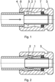
- the ending is connected with the hose for the distribution of water.
- the ending has a body 3 produced from plastic, which is designed for connection with the armature.
- the ending has a stop 4 with the inner conical surface 6 which is oriented against the conical surface 5 on the mouthpiece 1 .
- the mouthpiece 1 is placed in the cavity of the ending; it is slidably led in the body 3 and it is sealed against the body 3 by means of the sealing ring 7 .
- the mouthpiece 1 proceeds further by the waist 8 with the diameter which corresponds to the inner diameter of the hose.
- the sealing zone 9 follows upon the waist 8 .
- the mouthpiece 1 in this example of realization is inserted inside the body 3 through the opening in the circumferential stop 4.
- the outer diameter of the thickening 2 is smaller than the inner diameter of the opening in the circumferential stop 1 and at the same time the difference between the diameter of the stop 1 and the outer diameter of the thickening 2 is less than twice the thickness of the wall of the hose.
- the hose is inserted into the opening in the ending and pushed onto the mouthpiece 1 by pressure. Thereby the mouthpiece 1 is pushed into the body 3.
- the subsequent pulling of the hose or the effect of the overpressure of the medium inside the hose causes a movement of the mouthpiece 1 with the mounted hose outside the body 3.
- the hose, deformed in the zone thickening 2 has a diameter that is larger than the opening in the stop 4 and the pushing out of the mouthpiece 1 from the body 3 is stopped at the stop 4.
- the conical surface 6 on the stop 4 and the conical surface 5 on the mouthpiece 1 hold the hose and thereby ensure its tightness against the mouthpiece 1.
- the mouthpiece 1 can be once again moved into the body 3 of the ending; the visible space of the movement of the hose with the mouthpiece 1 does not affect the tightness of the join in any way.
- the first conical surface leads the hose during the pushing onto the mouthpiece 1.
- the second conical surface forms a support for the sealing ring 7 , whereby it delimits its course of movement during the pulling out of the mouthpiece 1.
- the body 3 with the circumferential wall and stop 4 is pressed from the plastic as a single component.
- the other independent component of the ending is the plastic mouthpiece 1.
- the sealing ring 7 keeps the mouthpiece 1 in the body 3 during the state without the mounted hose. After the hose is mounted, the mouthpiece 1 cannot be pulled out of the ending.
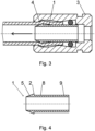
- Ending in this example according to figure 5 forms a part of the suction pipe of the engine.
- the mouthpiece 1 and the body 3 are produced as one whole from the plastic.
- the mouthpiece 1 is connected with the body 3 by means of flexible bellows, so-called accordion.
- a hose is mounted onto the mouthpiece 1 with approximately rectangular cross-section with rounder corners; the reverse movement of the mouthpiece 1 with the hose causes its locking on the stop 4.
- the stop 4 in this example has a form of a ring which has opening corresponding to the profile of the hose and the profile of the mouthpiece 1 , and it is connected with the body 3 by four draw rods.
- the draw rods produce an advantageous semi-solid fixing of the hose into the body 3, whereby the bellows causes prestress which keeps the pressure of the stop 4 on the hose, which ensures the tightness of the joint even in case of underpressure in the suction pipe.
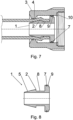
- the ending is designed for connection of the hose with the water valve.
- the ending has a plastic body 3 which has grooves on the outer circumference in order to simplify the screwing of the body 3 to the outer thread on the water valve.
- a flat circular seal (sealing) 10, leaning on the mount in the body 3, is used in order to seal the ending against the water valve.
- the body 3 has a circumferential stop 4 on one end, whereby the stop 4 is oriented against the thickening 2 on the mouthpiece 1_.
- the mouthpiece 1 is inserted inside the body 3 from the side which has a thread for connection to the water valve.
- the mouthpiece 1 has thickening 2 with a conical surface 5, it also has a waist 8 which is followed by a sealing zone 9.
- the sealing zone 9 in this example has a disc with a diameter larger than the outer diameter of the thickening 2.
- the mouthpiece 1 is placed in the cavity of the ending; it is slidably led in the body 3 and it is sealed against the body 3 by means of the sealing ring 7 .
- the disc is slidably led in the cylindrical cavity of the body 3.
- the hose is first mounted on the body 3 without the mouthpiece 1. Then the end of the hose is pulled onto the mouthpiece 1. The end of the hose is pulled on the thickening 2 and on the waist 8 towards the disc in the sealing zone 9. The body is moved to the end of the hose and the end of the hose together with the mouthpiece 1 is pushed inside the body 3. The body 3 with the sealing 10 is connected to the outlet of the water valve. The pressure of the water pushes the mouthpiece 1 against the stop 4 which presses onto the surface of the hose in the place of thickening 2. After the release the joint and the ending are simple to disassemble and they can be used repeatedly on other hoses with approximately similar diameter and thickness of the wall.
- the outer pull on the hose acts in the direction of the movement of the mouthpiece 1 with the mounted hose outside the body 3.
- the hose in the zone of thickening 2 has a diameter which is larger than the opening in the stop 4 and the pulling out of the mouthpiece 1 from the body 3 is stopped at the stop 4.
- the groove is produced on the inner diameter of the opening in the circumferential stop 4 and the "O" ring is inserted into the groove, whereby the ring holds the hose and allows the rotation of the hose with the mouthpiece 1 against the body 3.
- the body 3 is pressed from the plastic as a single component; the mouthpiece 1 is pressed as the other component. Both main components have solid form without fragile protrusions and flexible lamellas, such as those known in the state of the art.
Landscapes
- Engineering & Computer Science (AREA)
- General Engineering & Computer Science (AREA)
- Mechanical Engineering (AREA)
- Quick-Acting Or Multi-Walled Pipe Joints (AREA)
- Joints That Cut Off Fluids, And Hose Joints (AREA)
- Joints Allowing Movement (AREA)
- Shaping Of Tube Ends By Bending Or Straightening (AREA)
- Pipe Accessories (AREA)
- Nozzles (AREA)
Applications Claiming Priority (3)
| Application Number | Priority Date | Filing Date | Title |
|---|---|---|---|
| SK50056-2017U SK8164Y1 (sk) | 2017-06-09 | 2017-06-09 | Koncovka hadice, najmä ako pripájací prvok |
| SK50058-2018U SK8532Y1 (sk) | 2018-06-07 | 2018-06-07 | Koncovka hadice najmä ako pripojovací prvok |
| PCT/IB2018/054185 WO2018225044A1 (en) | 2017-06-09 | 2018-06-09 | Hose ending, mainly as connecting element |
Publications (3)
| Publication Number | Publication Date |
|---|---|
| EP3635285A1 EP3635285A1 (en) | 2020-04-15 |
| EP3635285B1 true EP3635285B1 (en) | 2024-08-21 |
| EP3635285C0 EP3635285C0 (en) | 2024-08-21 |
Family
ID=64567012
Family Applications (1)
| Application Number | Title | Priority Date | Filing Date |
|---|---|---|---|
| EP18746748.5A Active EP3635285B1 (en) | 2017-06-09 | 2018-06-09 | Ending for a hose, mainly as connecting element |
Country Status (11)
| Country | Link |
|---|---|
| US (1) | US11821555B2 (enExample) |
| EP (1) | EP3635285B1 (enExample) |
| JP (1) | JP7394450B2 (enExample) |
| KR (1) | KR20200016957A (enExample) |
| CN (1) | CN110832241B (enExample) |
| AU (1) | AU2018280611B2 (enExample) |
| CA (1) | CA3065040A1 (enExample) |
| MX (1) | MX2019014686A (enExample) |
| RU (1) | RU2734157C1 (enExample) |
| WO (1) | WO2018225044A1 (enExample) |
| ZA (1) | ZA201907790B (enExample) |
Families Citing this family (5)
| Publication number | Priority date | Publication date | Assignee | Title |
|---|---|---|---|---|
| JP5996000B2 (ja) * | 2015-01-23 | 2016-09-21 | 日本ピラー工業株式会社 | 樹脂製管継手構造 |
| CN111331074A (zh) * | 2020-04-07 | 2020-06-26 | 马鞍山博越精密机械有限公司 | 一种汽车制动卡钳支架毛坯加工工艺 |
| CN116635660B (zh) * | 2020-11-26 | 2025-12-16 | 胡斯华纳有限公司 | 软管连接器 |
| CN112555542B (zh) * | 2020-12-21 | 2022-04-29 | 武汉船舶通信研究所(中国船舶重工集团公司第七二二研究所) | 管道连接结构和管道连接方法 |
| CN115076484B (zh) * | 2022-07-06 | 2023-12-22 | 高邮市顺通消防装备有限公司 | 一种避免受高温压缩可稳定对接的消防接口 |
Family Cites Families (26)
| Publication number | Priority date | Publication date | Assignee | Title |
|---|---|---|---|---|
| CH128924A (fr) * | 1927-08-11 | 1928-11-16 | Francois Planque | Raccord amovible d'organes tubulaires. |
| US1843123A (en) * | 1930-02-03 | 1932-02-02 | James Clarence Perkins | High pressure hose connection |
| US1853584A (en) * | 1931-02-17 | 1932-04-12 | Albert D Stoddard | Hose clamp |
| US2047714A (en) * | 1934-12-29 | 1936-07-14 | Ingersoll Rand Co | Hose coupling |
| GB692787A (en) * | 1950-04-06 | 1953-06-17 | Bowden Eng Ltd | Improvements in and relating to flexible hose couplings |
| JPS5144183Y2 (enExample) * | 1971-09-13 | 1976-10-27 | ||
| JPS5552148Y2 (enExample) * | 1974-01-24 | 1980-12-03 | ||
| JPS596314Y2 (ja) * | 1974-12-24 | 1984-02-27 | (有) ニツタ ムアカンパニ− | 管継手 |
| GB2051280B (en) * | 1979-06-20 | 1983-06-22 | Guest Southern Ltd John | Coupling for tubes |
| JPS57103321U (enExample) * | 1980-12-16 | 1982-06-25 | ||
| JPH0633844B2 (ja) * | 1987-09-29 | 1994-05-02 | ブリヂストンフロ−テック株式会社 | 管継手 |
| GB2251044A (en) * | 1990-12-21 | 1992-06-24 | Ford Motor Co | Tube coupling |
| JPH0518485A (ja) * | 1991-07-10 | 1993-01-26 | Sekisui Chem Co Ltd | 管の接続部構造 |
| JPH076592U (ja) * | 1993-06-28 | 1995-01-31 | 堤 繁 | ホース着脱用器具 |
| US5794986A (en) * | 1994-09-15 | 1998-08-18 | Infrasonics, Inc. | Semi-disposable ventilator breathing circuit tubing with releasable coupling |
| US5498043A (en) * | 1995-01-25 | 1996-03-12 | Plastic Specialties And Technologies, Inc. | Hose fitting having ferrule anti-rotation ratchet teeth |
| US6344272B1 (en) * | 1997-03-12 | 2002-02-05 | Wm. Marsh Rice University | Metal nanoshells |
| IT1309925B1 (it) * | 1999-10-27 | 2002-02-05 | Irritec S R L | Elemento di raccordo per tubi, in particolare per tubi di materiaplastica. |
| GB0402564D0 (en) * | 2004-02-05 | 2004-03-10 | Maunder Roy P | Tube connector |
| JP4062325B2 (ja) * | 2005-07-14 | 2008-03-19 | 株式会社ニチリン | 異種金属管の接続構造 |
| US7527300B2 (en) * | 2005-08-24 | 2009-05-05 | Beckman Coulter, Inc. | Flexible tubing connector |
| US7648178B1 (en) * | 2008-10-22 | 2010-01-19 | Andros Matthew J | Connector for joining with agricultural drip tape |
| BR112012011760A2 (pt) | 2009-11-20 | 2018-03-27 | Puku Ltd | conector para prender um tubo deformável elasticamente e kit de montagem. |
| JP5878143B2 (ja) * | 2013-05-08 | 2016-03-08 | 日本ピラー工業株式会社 | 合成樹脂製管継手 |
| JP5977295B2 (ja) | 2014-08-25 | 2016-08-24 | 株式会社タカギ | ホース継手 |
| WO2016132745A1 (ja) | 2015-02-19 | 2016-08-25 | 日立金属株式会社 | 管継手 |
-
2018
- 2018-06-09 MX MX2019014686A patent/MX2019014686A/es unknown
- 2018-06-09 EP EP18746748.5A patent/EP3635285B1/en active Active
- 2018-06-09 CA CA3065040A patent/CA3065040A1/en active Pending
- 2018-06-09 WO PCT/IB2018/054185 patent/WO2018225044A1/en not_active Ceased
- 2018-06-09 CN CN201880044031.3A patent/CN110832241B/zh active Active
- 2018-06-09 KR KR1020207000577A patent/KR20200016957A/ko not_active Ceased
- 2018-06-09 AU AU2018280611A patent/AU2018280611B2/en active Active
- 2018-06-09 JP JP2019567311A patent/JP7394450B2/ja active Active
- 2018-06-09 US US16/619,221 patent/US11821555B2/en active Active
- 2018-06-09 RU RU2019140791A patent/RU2734157C1/ru active
-
2019
- 2019-11-25 ZA ZA2019/07790A patent/ZA201907790B/en unknown
Also Published As
| Publication number | Publication date |
|---|---|
| US11821555B2 (en) | 2023-11-21 |
| CA3065040A1 (en) | 2018-12-13 |
| US20200166166A1 (en) | 2020-05-28 |
| WO2018225044A1 (en) | 2018-12-13 |
| AU2018280611B2 (en) | 2024-06-13 |
| MX2019014686A (es) | 2020-08-03 |
| CN110832241A (zh) | 2020-02-21 |
| AU2018280611A1 (en) | 2019-12-19 |
| EP3635285A1 (en) | 2020-04-15 |
| ZA201907790B (en) | 2021-03-31 |
| JP7394450B2 (ja) | 2023-12-08 |
| JP2020522655A (ja) | 2020-07-30 |
| KR20200016957A (ko) | 2020-02-17 |
| RU2734157C1 (ru) | 2020-10-13 |
| CN110832241B (zh) | 2021-11-16 |
| EP3635285C0 (en) | 2024-08-21 |
| BR112019025768A2 (pt) | 2020-06-23 |
Similar Documents
| Publication | Publication Date | Title |
|---|---|---|
| EP3635285B1 (en) | Ending for a hose, mainly as connecting element | |
| US4328979A (en) | Adaptor connecting piece for conduits designed to carry gaseous or liquid media | |
| US20110025047A1 (en) | End fitting for holding a high pressure capillary tube | |
| EP2827038B1 (en) | Tube joint | |
| JP5641552B1 (ja) | 管締結構造 | |
| US7380836B2 (en) | Connection device for fluid lines | |
| US5261706A (en) | Apparatus for attaching a hose to a fitting | |
| CA2080359A1 (en) | Apparatus for attaching a hose to a fitting | |
| US3707302A (en) | High performance fitting | |
| AU2016285084A1 (en) | Faucet coupling structure | |
| CN107268753B (zh) | 一种密封连接机构 | |
| US4846505A (en) | Connecting piece | |
| EP0648319A1 (en) | Fluid line connector fitting | |
| KR20090013169U (ko) | 튜브 커플링 취부 및 탈거장치 | |
| EP1186822B1 (en) | Quick-connect coupling | |
| JPH01234686A (ja) | 管継手 | |
| CZ263597A3 (cs) | Trubková spojka a způsob připevnění trubky ke spojkovému členu | |
| BR112019025768B1 (pt) | Terminação de mangueira, principalmente como elemento de conexão | |
| JP6294986B1 (ja) | 直管パイプ用継手 | |
| SK8532Y1 (sk) | Koncovka hadice najmä ako pripojovací prvok | |
| EP0372604B1 (en) | Connector for devices designed to be fitted onto conduits in a pressurized fluid system | |
| EP0533638B1 (en) | Joint for fast connecting and disconnecting pipes | |
| JPH1061847A (ja) | 管継手 | |
| SK8164Y1 (sk) | Koncovka hadice, najmä ako pripájací prvok | |
| HK1004011B (en) | Connector for devices designed to be fitted onto conduits in a pressurized fluid system |
Legal Events
| Date | Code | Title | Description |
|---|---|---|---|
| STAA | Information on the status of an ep patent application or granted ep patent |
Free format text: STATUS: UNKNOWN |
|
| STAA | Information on the status of an ep patent application or granted ep patent |
Free format text: STATUS: THE INTERNATIONAL PUBLICATION HAS BEEN MADE |
|
| PUAI | Public reference made under article 153(3) epc to a published international application that has entered the european phase |
Free format text: ORIGINAL CODE: 0009012 |
|
| STAA | Information on the status of an ep patent application or granted ep patent |
Free format text: STATUS: REQUEST FOR EXAMINATION WAS MADE |
|
| 17P | Request for examination filed |
Effective date: 20200108 |
|
| AK | Designated contracting states |
Kind code of ref document: A1 Designated state(s): AL AT BE BG CH CY CZ DE DK EE ES FI FR GB GR HR HU IE IS IT LI LT LU LV MC MK MT NL NO PL PT RO RS SE SI SK SM TR |
|
| AX | Request for extension of the european patent |
Extension state: BA ME |
|
| DAV | Request for validation of the european patent (deleted) | ||
| DAX | Request for extension of the european patent (deleted) | ||
| STAA | Information on the status of an ep patent application or granted ep patent |
Free format text: STATUS: EXAMINATION IS IN PROGRESS |
|
| 17Q | First examination report despatched |
Effective date: 20220217 |
|
| GRAP | Despatch of communication of intention to grant a patent |
Free format text: ORIGINAL CODE: EPIDOSNIGR1 |
|
| STAA | Information on the status of an ep patent application or granted ep patent |
Free format text: STATUS: GRANT OF PATENT IS INTENDED |
|
| INTG | Intention to grant announced |
Effective date: 20240318 |
|
| GRAS | Grant fee paid |
Free format text: ORIGINAL CODE: EPIDOSNIGR3 |
|
| GRAA | (expected) grant |
Free format text: ORIGINAL CODE: 0009210 |
|
| STAA | Information on the status of an ep patent application or granted ep patent |
Free format text: STATUS: THE PATENT HAS BEEN GRANTED |
|
| AK | Designated contracting states |
Kind code of ref document: B1 Designated state(s): AL AT BE BG CH CY CZ DE DK EE ES FI FR GB GR HR HU IE IS IT LI LT LU LV MC MK MT NL NO PL PT RO RS SE SI SK SM TR |
|
| REG | Reference to a national code |
Ref country code: GB Ref legal event code: FG4D |
|
| REG | Reference to a national code |
Ref country code: CH Ref legal event code: EP |
|
| REG | Reference to a national code |
Ref country code: IE Ref legal event code: FG4D |
|
| REG | Reference to a national code |
Ref country code: DE Ref legal event code: R096 Ref document number: 602018073346 Country of ref document: DE |
|
| U01 | Request for unitary effect filed |
Effective date: 20240919 |
|
| U07 | Unitary effect registered |
Designated state(s): AT BE BG DE DK EE FI FR IT LT LU LV MT NL PT RO SE SI Effective date: 20241010 |
|
| PG25 | Lapsed in a contracting state [announced via postgrant information from national office to epo] |
Ref country code: NO Free format text: LAPSE BECAUSE OF FAILURE TO SUBMIT A TRANSLATION OF THE DESCRIPTION OR TO PAY THE FEE WITHIN THE PRESCRIBED TIME-LIMIT Effective date: 20241121 |
|
| PG25 | Lapsed in a contracting state [announced via postgrant information from national office to epo] |
Ref country code: PL Free format text: LAPSE BECAUSE OF FAILURE TO SUBMIT A TRANSLATION OF THE DESCRIPTION OR TO PAY THE FEE WITHIN THE PRESCRIBED TIME-LIMIT Effective date: 20240821 Ref country code: GR Free format text: LAPSE BECAUSE OF FAILURE TO SUBMIT A TRANSLATION OF THE DESCRIPTION OR TO PAY THE FEE WITHIN THE PRESCRIBED TIME-LIMIT Effective date: 20241122 |
|
| PG25 | Lapsed in a contracting state [announced via postgrant information from national office to epo] |
Ref country code: IS Free format text: LAPSE BECAUSE OF FAILURE TO SUBMIT A TRANSLATION OF THE DESCRIPTION OR TO PAY THE FEE WITHIN THE PRESCRIBED TIME-LIMIT Effective date: 20241221 |
|
| PG25 | Lapsed in a contracting state [announced via postgrant information from national office to epo] |
Ref country code: HR Free format text: LAPSE BECAUSE OF FAILURE TO SUBMIT A TRANSLATION OF THE DESCRIPTION OR TO PAY THE FEE WITHIN THE PRESCRIBED TIME-LIMIT Effective date: 20240821 |
|
| PG25 | Lapsed in a contracting state [announced via postgrant information from national office to epo] |
Ref country code: ES Free format text: LAPSE BECAUSE OF FAILURE TO SUBMIT A TRANSLATION OF THE DESCRIPTION OR TO PAY THE FEE WITHIN THE PRESCRIBED TIME-LIMIT Effective date: 20240821 Ref country code: RS Free format text: LAPSE BECAUSE OF FAILURE TO SUBMIT A TRANSLATION OF THE DESCRIPTION OR TO PAY THE FEE WITHIN THE PRESCRIBED TIME-LIMIT Effective date: 20241121 |
|
| REG | Reference to a national code |
Ref country code: SK Ref legal event code: T3 Ref document number: E 45483 Country of ref document: SK |
|
| PG25 | Lapsed in a contracting state [announced via postgrant information from national office to epo] |
Ref country code: RS Free format text: LAPSE BECAUSE OF FAILURE TO SUBMIT A TRANSLATION OF THE DESCRIPTION OR TO PAY THE FEE WITHIN THE PRESCRIBED TIME-LIMIT Effective date: 20241121 Ref country code: PL Free format text: LAPSE BECAUSE OF FAILURE TO SUBMIT A TRANSLATION OF THE DESCRIPTION OR TO PAY THE FEE WITHIN THE PRESCRIBED TIME-LIMIT Effective date: 20240821 Ref country code: NO Free format text: LAPSE BECAUSE OF FAILURE TO SUBMIT A TRANSLATION OF THE DESCRIPTION OR TO PAY THE FEE WITHIN THE PRESCRIBED TIME-LIMIT Effective date: 20241121 Ref country code: IS Free format text: LAPSE BECAUSE OF FAILURE TO SUBMIT A TRANSLATION OF THE DESCRIPTION OR TO PAY THE FEE WITHIN THE PRESCRIBED TIME-LIMIT Effective date: 20241221 Ref country code: HR Free format text: LAPSE BECAUSE OF FAILURE TO SUBMIT A TRANSLATION OF THE DESCRIPTION OR TO PAY THE FEE WITHIN THE PRESCRIBED TIME-LIMIT Effective date: 20240821 Ref country code: GR Free format text: LAPSE BECAUSE OF FAILURE TO SUBMIT A TRANSLATION OF THE DESCRIPTION OR TO PAY THE FEE WITHIN THE PRESCRIBED TIME-LIMIT Effective date: 20241122 Ref country code: ES Free format text: LAPSE BECAUSE OF FAILURE TO SUBMIT A TRANSLATION OF THE DESCRIPTION OR TO PAY THE FEE WITHIN THE PRESCRIBED TIME-LIMIT Effective date: 20240821 |
|
| PG25 | Lapsed in a contracting state [announced via postgrant information from national office to epo] |
Ref country code: SM Free format text: LAPSE BECAUSE OF FAILURE TO SUBMIT A TRANSLATION OF THE DESCRIPTION OR TO PAY THE FEE WITHIN THE PRESCRIBED TIME-LIMIT Effective date: 20240821 |
|
| PLBE | No opposition filed within time limit |
Free format text: ORIGINAL CODE: 0009261 |
|
| STAA | Information on the status of an ep patent application or granted ep patent |
Free format text: STATUS: NO OPPOSITION FILED WITHIN TIME LIMIT |
|
| PGFP | Annual fee paid to national office [announced via postgrant information from national office to epo] |
Ref country code: GB Payment date: 20250606 Year of fee payment: 8 |
|
| PGFP | Annual fee paid to national office [announced via postgrant information from national office to epo] |
Ref country code: SK Payment date: 20250606 Year of fee payment: 8 |
|
| PGFP | Annual fee paid to national office [announced via postgrant information from national office to epo] |
Ref country code: CZ Payment date: 20250606 Year of fee payment: 8 |
|
| 26N | No opposition filed |
Effective date: 20250522 |
|
| U20 | Renewal fee for the european patent with unitary effect paid |
Year of fee payment: 8 Effective date: 20250627 |