EP3634842B1 - Folding bicycle - Google Patents
Folding bicycle Download PDFInfo
- Publication number
- EP3634842B1 EP3634842B1 EP18729053.1A EP18729053A EP3634842B1 EP 3634842 B1 EP3634842 B1 EP 3634842B1 EP 18729053 A EP18729053 A EP 18729053A EP 3634842 B1 EP3634842 B1 EP 3634842B1
- Authority
- EP
- European Patent Office
- Prior art keywords
- bar
- bicycle
- oblique
- joints
- bolt
- Prior art date
- Legal status (The legal status is an assumption and is not a legal conclusion. Google has not performed a legal analysis and makes no representation as to the accuracy of the status listed.)
- Active
Links
- 238000013459 approach Methods 0.000 claims description 6
- 230000000295 complement effect Effects 0.000 claims description 3
- 238000005452 bending Methods 0.000 description 2
- 230000006835 compression Effects 0.000 description 2
- 238000007906 compression Methods 0.000 description 2
- 230000000694 effects Effects 0.000 description 2
- 241000920340 Pion Species 0.000 description 1
- 230000000903 blocking effect Effects 0.000 description 1
- 210000004027 cell Anatomy 0.000 description 1
- 230000001419 dependent effect Effects 0.000 description 1
- 230000000994 depressogenic effect Effects 0.000 description 1
- 238000006073 displacement reaction Methods 0.000 description 1
- 230000002452 interceptive effect Effects 0.000 description 1
- 239000011295 pitch Substances 0.000 description 1
- 238000005096 rolling process Methods 0.000 description 1
Images


Classifications
-
- B—PERFORMING OPERATIONS; TRANSPORTING
- B62—LAND VEHICLES FOR TRAVELLING OTHERWISE THAN ON RAILS
- B62K—CYCLES; CYCLE FRAMES; CYCLE STEERING DEVICES; RIDER-OPERATED TERMINAL CONTROLS SPECIALLY ADAPTED FOR CYCLES; CYCLE AXLE SUSPENSIONS; CYCLE SIDE-CARS, FORECARS, OR THE LIKE
- B62K15/00—Collapsible or foldable cycles
- B62K15/006—Collapsible or foldable cycles the frame being foldable
- B62K15/008—Collapsible or foldable cycles the frame being foldable foldable about 2 or more axes
-
- B—PERFORMING OPERATIONS; TRANSPORTING
- B62—LAND VEHICLES FOR TRAVELLING OTHERWISE THAN ON RAILS
- B62K—CYCLES; CYCLE FRAMES; CYCLE STEERING DEVICES; RIDER-OPERATED TERMINAL CONTROLS SPECIALLY ADAPTED FOR CYCLES; CYCLE AXLE SUSPENSIONS; CYCLE SIDE-CARS, FORECARS, OR THE LIKE
- B62K3/00—Bicycles
- B62K3/02—Frames
- B62K3/04—Frames having a substantially horizontal top bar
Definitions
- the present disclosure relates to a folding bicycle, that is to say a bicycle which can be deformed between an unfolded position in which the bicycle can be used as a means of transport and a folded position in which the size of the bicycle is less. Once folded, the bike can be stored or transported more easily.
- the invention relates to a folding bicycle according to the appended independent claims 1 and 2. Particular embodiments are defined by the dependent claims.
- Such a folding bicycle includes a front wheel, a rear wheel and a frame.
- the frame comprises a front frame part on which the front wheel is mounted, via a pivoting fork, and a rear frame part on which the rear wheel is mounted.
- the front frame part includes a top bar, a saddle bar and a slash.
- the seat bar is also part of the rear frame part.
- the rear frame portion may include at least one seat stay, at least one lower bar, and the saddle bar.
- the oblique bar comprises an upper oblique rod and a lower oblique rod.
- the lower oblique rod, the upper oblique rod, the upper bar and the saddle bar are interconnected by joints, in that order, so as to form a deformable hinged quadrilateral between a folded position and an unfolded position.
- the deformable hinged quadrilateral is configured such that, on deforming to its folded position, the bicycle folds lengthwise with the front and rear wheels moving transversely apart from each other while moving closer together lengthwise until the front wheel is superimposed on the rear wheel in a transverse direction of the bicycle.
- the front frame part comprises an upper bar, a portion of the saddle bar, a junction bar and an oblique bar.
- the top bar, the saddle bar portion, the junction bar and the slash are connected together, in that order, by hinges so as to form a deformable hinged quadrilateral between a folded position and an unfolded position.
- the deformable hinged quadrilateral is configured such that, on deforming to its folded position, the bicycle folds lengthwise with the front and rear wheels moving transversely apart from each other while moving closer together lengthwise until the front wheel is superimposed on the rear wheel in a transverse direction of the bicycle.
- the front wheel when the bicycle is in the folded position, the front wheel is superimposed on the rear wheel in a transverse direction of the bicycle.
- the front wheel and the rear wheel are arranged substantially opposite each other in the transverse direction of the bicycle, it being understood that these wheels may be slightly offset from one another. in a direction perpendicular to the transverse direction, without departing from the scope of the invention.
- the length of the bicycle is considered between the front end of the front wheel and the rear end of the rear wheel of the bicycle.
- the longitudinal direction of the bicycle is the direction along the length of the bicycle. The direction longitudinal therefore corresponds to the front-rear direction of the bicycle when the latter is in the unfolded position, the front and the rear being defined with respect to the normal direction of travel of the bicycle when the latter is used as a means of transport.
- the height of the bicycle is considered vertically when the bicycle rests on its wheels, in the unfolded position, on a horizontal surface.
- the median plane of the rear wheel of the bicycle is called the “midplane” of the bicycle.
- the front and rear wheels are in the midplane and the longitudinal axis of the bicycle is contained in this plane.
- the transverse direction is the direction perpendicular to the midplane of the bicycle.
- the fact that the front and rear wheels are superimposed in the folded position in the transverse direction makes it possible to limit the size of the bicycle in the folded position while keeping the wheels of normal size, ie of diameter proportional to the size of the user of the bicycle. .
- the comfort and stability of the bicycle when using it in the unfolded position are thus preserved and, in the folded position, the bicycle can be easily stored (for example in an apartment, a cellar, on a balcony, etc.) and easily transported (for example in a car trunk, in public transport, etc.).
- Said articulated quadrilateral is delimited by the four aforementioned articulations which form the four vertices of the quadrilateral.
- the four sides of the quadrilateral are, in turn, formed by the elements that connect the joints between them.
- the four sides are formed essentially by the lower oblique rod, the upper oblique rod, the upper bar and the saddle bar, respectively.
- the four sides are formed essentially by the upper bar, the upper portion of the saddle bar, the junction bar and the slash, respectively.
- the aforementioned rods and bars are generally essentially straight, but they are not necessarily so. The concept of a quadrilateral should therefore not be interpreted in the strict sense in this regard. By example, these rods and bars may be curved or in the form of broken lines without departing from the scope of the invention.
- the joints are pivot links. These structurally simple connections make it possible to guide the four sides of the deformable articulated quadrilateral in rotation while allowing only one rotation around the axis of the connection. Folding the bicycle is facilitated by this guidance. The bike can therefore be folded flexibly, quickly and intuitively.
- the joints are pivot links and the axes of these links intersect at the same point.
- the axes of the links are mutually parallel.
- the axes of the connections are preferably inclined at the same angle with respect to the transverse direction of the bicycle.
- the axes of the links can be horizontal when the bicycle is unfolded and rests on a horizontal surface.
- the rear frame portion is dimensionally stable. This improves the stability of the bicycle during use.
- the bicycle includes a locking system for locking the articulated quadrilateral in its unfolded position.
- the locking system can be provided between the lower oblique rod and the upper oblique rod, or between the portion of the saddle bar and the junction bar.
- the locking system may include, for example, a clamp or a clamp held by a screw, or a hook system operated by a lever.
- the locking system comprises a bolt slidably mounted inside one of the oblique rods, between an extended position and a retracted position, and a keeper arranged inside the other oblique rod and cooperating with the bolt in the extended position to prevent the relative rotation of the oblique rods around the joint.
- one of the oblique rods has an extension extending axially beyond the joint, while the other rod has a cutout whose shape is complementary to that of the extension, and the bolt slides axially inside the extension. This configuration makes it possible to ensure better locking of the articulated quadrilateral in its unfolded position.
- the locking system comprises an unlocking lever mounted on the same oblique rod as the bolt and cooperating with the bolt to drive the latter towards its retracted position, and thus allow the rotation of the oblique rods one. compared to each other.
- the locking system comprises a lock mounted movably in said extension, between a locking position of the bolt and an unlocking position of the bolt.
- the lock With reference to the central axis of the oblique rod, the lock is movable in translation laterally but not axially.
- a pin is provided in front of the lock, on the side face of the cutout, so that the pin comes to press on the lock to unlock the bolt when the oblique rods are unfolded to be aligned.
- the bicycle includes a locking system for locking the bicycle crankset in a particular position when folding or unfolding the bicycle.
- the crankset may include a bottom bracket rotating around an axis and the locking system may include a pin fixed on the lower oblique rod near the plate; and a stopper fixed on the inside face of the plate. In the unfolded position, the pin does not interfere with the travel of the stopper and the plate can therefore rotate freely around its axis.
- the pin approaches the axis of the plate and cuts the stroke of the stop. The bottom bracket can then no longer turn freely.
- the horizontal and vertical directions are considered with reference to the unfolded position of the bicycle when the latter rests, under normal conditions of use, on a horizontal surface.
- the top and bottom are defined in the vertical direction.
- the front and rear, right and left, are defined in relation to the normal rolling direction of the bicycle.
- the saddle bar 5 is, typically, a tube inside which the saddle post 4 is slidably mounted, so that the saddle 3 can be adjusted in height.
- the bicycle has a frame comprising a rear frame part A (sometimes called a rear triangle) and a front frame part C (sometimes called a front triangle or central triangle).
- the rear frame part A is formed by the saddle bar 5, at least one seat stay 8 and at least one lower bar 9 (sometimes called a chain bar).
- the stay 8 and the lower bar 9 are doubled (ie there are two seat stays and two lower bars) and located on either side of the rear wheel 2.
- the left and right shrouds are respectively denoted 8g and 8d
- the lower left and right bars are respectively denoted 9g and 9d.
- the fork 7 if it is not single-sided, comprises a left fork arm 7g and a right fork arm 7d.
- the front frame part C is formed by the saddle bar 5, an upper bar 10 (sometimes called a horizontal bar) and an oblique bar 11.
- a head tube 12 is attached to the front frame part C, at the top. before this part.
- the fork 7 and the handlebars 6 pivot inside the steering tube.
- the bicycle of the figure 1 is equipped with a crankset (not shown) which is fixed to a bottom bracket 13, the axis of which is located at the intersection of the saddle bar 5, of the oblique bar 11 and of the lower bar (s) 9.
- the figure 2A shows an example of a folding bicycle according to the invention, in the unfolded position, seen in profile.
- the oblique bar is formed in two parts articulated to each other by the articulation P4: the upper oblique rod 14 and the lower oblique rod 15.
- the bars and rods 5, 10, 14, 15 which form the four sides of the articulated quadrilateral D are rigid.
- the steering tube 12 forms an integral part of the upper oblique rod 14 and forms the upper end of the latter.
- the joint P2 connects this steering tube 12 to the horizontal bar 10.
- the steering tube 12 could however be connected differently to the upper oblique rod 14 or to the horizontal bar 10.
- the steering tube may be an integral part. of the horizontal bar 10 and form the front end thereof.
- the joint P2 can connect the steering tube 12 to the upper oblique rod 14.
- the articulation P3 is located near the axis of the bottom bracket 13 but is not necessarily positioned on this axis.
- the frame of the bike figure 2 thus comprises a front frame part on which the front wheel 1 is mounted, via the pivoting fork 7, and a rear frame part A on which the rear wheel 2 is mounted.
- the front frame part forming the articulated quadrilateral D comprises the upper bar 10, the saddle bar 5 and the oblique bar formed by the lower oblique rod 15 and the upper oblique rod 14.
- the rear frame part A comprises the stay (s) 8, the lower bar (s) 9 and the saddle bar 5.
- the articulated quadrilateral D In its unfolded position shown on the figure 2A , the articulated quadrilateral D has a shape close to the triangle.
- the upper oblique rod 14 and the rod lower oblique 15 are substantially aligned and together form one side of said triangle.
- a deformable articulated quadrilateral connected by joints offering only one degree of freedom in rotation (rotation alone or combined with a translation) offers the advantage of being able to fold and unfold easily without having to disconnect one of its elements.
- the bicycle has a rigidity substantially equivalent to that of a conventional bicycle like that of the figure 1 .
- FIG 8 An example of a locking system 40 is shown in figure 8 .
- This system comprises an eccentric lever 41 fixed to the lower oblique rod 15, a ring 42 passed around the lever 41 and a hook 43 fixed to the upper oblique tube 14.
- the hook 43, the ring 42 and the lever 41 cooperate so that , when the ring 42 is hooked on the hook 43, the pivoting of the lever 41 puts the ring 42 in tension.
- the articulation P4 which connects the upper 14 and lower 15 oblique rods together, is located on one side of the rods 14, 15 when these are aligned.
- the pivot axis I4 of the joint is oriented perpendicularly and offset from the central axis of the rods 14 and 15.
- the locking system is located on the side opposite the joint P4, relative to the central axis rods 14 and 15.
- this system is locked by tensioning the ring 42, it prevents any relative movement between the rods 14, 15 and the joint P4 is blocked; the rods 14, 15 are kept aligned with each other, as shown in figure 8 .
- this is only an example of a locking system and other systems could be considered.
- the figures 10A to 10C and 11 show another example of a locking system located at the level of the articulation P4 which connects the upper 14 and lower 15 oblique rods to one another.
- the articulation P4 is located on one side of the rods 14, 15 when the latter are aligned.
- the articulation P4 is offset laterally with respect to the central axis of the rods, when the bicycle is unfolded.
- "axial" or “axially” refer to a parallel direction. to the central axis of the rods 14, 15, when the bicycle is unfolded
- lateral or “laterally” refer to a direction perpendicular to the axial direction.
- One of the rods, in the example rod 15, has an extension 15a extending axially beyond the articulation P4, while the other rod 14 has a cutout 14a whose shape is complementary to that of the joint. extension 15a.
- the extension 15a When the bicycle is unfolded, the extension 15a is housed in the cutout 14a.
- the bolt 21 is housed at least in part in the extension 15a and slides axially inside the latter, while the keeper 23 is provided at the level of the cutout 14a. In the extended position, the bolt 21 protrudes at the free end of the extension 15a.
- the zone of engagement of the bolt 21 in the keeper 23 is offset axially with respect to the articulation P4. Such a configuration makes it possible to obtain better locking.
- the bolt 21 In the extended position, the bolt 21 is engaged or pressed into the strike 23 (cf. figure 10A ). A compression spring 26 can act on the bolt 21 to keep it in this depressed position.
- a lock 27 can be mounted in the lower oblique rod 15 to keep the bolt 21 in its retracted position (cf. figures 10B, 10C ).
- the lock 27 at least partially surrounds the bolt 21 so that a first end 27a of the lock is located on one side of the bolt 21 and the opposite end of the lock, or second end 27b, is located on the other side of the bolt 21.
- the latch 27 is mounted inside the extension 15a of the rod 15 and is movable in translation in a lateral direction. On the other hand, the lock 27 is not axially movable.
- a notch 29 is provided in a lateral face of the bolt 21 to receive the second end 27b of the latch 27.
- a groove 31 may be formed in the lateral face of the bolt 21 located opposite the notch 29 to receive the first end 27a of the lock.
- the first end 27a of the lock In the unlocked position, the first end 27a of the lock is engaged in the groove 31, as shown in figure 10A , and this end 27a slides axially in the groove 31 when the bolt 21 slides. The end 27a comes out of the groove 31 when the second end 27b enters the notch 29, and vice versa.
- a pin 50 can be provided, opposite the first end 27a, on the side face of the cutout 14a of the upper oblique rod 14, so that the pin 50 comes to press on the end 27a to make it penetrate. in the groove 31, and so that the second end 27b comes out of the notch 29, thus unlocking the bolt 21, when the bicycle is unfolded.
- the lever 24 is pivotally mounted on the lower oblique rod 15 about an axis 25 and cooperates with a stop 22 of the bar 21. This lever 24 makes it possible to act against the return force exerted by the spring 26 on the bolt 21.
- the user raises the lever 24 which acts on the stop 22 to slide the bolt 21 towards its retracted position and compress the spring 26, until the second end 27b of the latch 27, under the effect of the spring 28, enters the notch 29.
- the bolt 21 is disengaged from the keeper 23 and maintained in this retracted position by the latch 27.
- the lever 24 also includes one or more pushers 24a.
- the pusher (s) 24a press on the upper oblique rod 14, forcing it to move away from the lower oblique rod 15 by pivoting around the joint P4.
- the pin 50 stops pressing on the first end 27a of the latch 27, which makes the lateral displacement of the latch 27 possible and allows the second end 27b to engage in notch 29. Latch 27 then maintains bolt 21 in its retracted position.
- a return device may be provided to allow the lever 24 to return against the lower oblique rod 15, as shown in FIG. figure 10A or 10C .
- the figure 11 is a perspective view of the unlocking system described above, in a position identical to that of the figure 10C . Thanks to such an unlocking system, the bicycle has a simple mechanism allowing easy unlocking of the bicycle, and automatic locking when unfolding.
- the shapes of the rods 14 and 15 could be reversed, i.e. the bolt 21 could be mounted on the upper oblique rod 14 and the keeper 23 be provided in the lower oblique rod 15.
- the articulated quadrilateral D In folded position ( figure 2C ), the articulated quadrilateral D reaches an almost flattened shape, allowing all of the elements that compose it to fold up into a small space, close to the wheels, in order to limit the bulk of the folded bicycle as much as possible.
- the respective positions of the joints P1, P2, P3 and P4 and the dimensions of the bars and rods 5, 10, 14, 15 are adapted so that, in this folded position, the front wheel 1 and the rear wheel 2 are superimposed in the transverse direction of the bicycle.
- This configuration makes it possible to limit the bulk of the folded bicycle as much as possible. It also allows the user to roll the folded bicycle on the ground and thus ride with the folded bicycle without having to carry it.
- the saddle 3 can also be retracted in the folded position, by sliding the seat post 4 inside the saddle bar 5 to the lowest position ( figure 2C ).
- a normal-size bicycle is thus obtained which is simple and reliable to fold, does not require dismantling a part of the frame or a wheel, having a rigid structure in the unfolded position and offering a small footprint in the folded position.
- the joints P1, P2, P3 and P4 are helical links, that is to say links offering mobility according to rotational and translational movements combined, whose axes are perpendicular to the median plane of the bicycle, and whose directions of rotation as well as the respective pitches are calculated so that, during folding, the plane of the front frame and of the front wheel 1 deviates transversely from that of the part of the rear frame A and of the rear wheel 2.
- helical links that is to say links offering mobility according to rotational and translational movements combined, whose axes are perpendicular to the median plane of the bicycle, and whose directions of rotation as well as the respective pitches are calculated so that, during folding, the plane of the front frame and of the front wheel 1 deviates transversely from that of the part of the rear frame A and of the rear wheel 2.
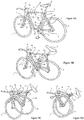
- the figure 3 describes another example of a bicycle, seen from above.
- the joints P1, P2, P3 and P4 are pivot links whose axes, respectively called I1, I2, I3 and I4, are parallel and inclined at the same angle A1 by relative to the transverse direction T of the bicycle.
- the axes I1, I2, I3 and I4 are inclined at an angle A1 in the direction of clockwise (viewed from above) or towards the rear on the right part of the bicycle.
- This configuration makes it possible, during folding, if the upper bar 10 is considered as fixed, to pivot the front part of the bicycle, in particular the front wheel 1, towards the rear around the articulation P2 while moving away transversely. , on the left on the figure 3 , of the upper bar 10.
- the rear part of the bicycle, in particular the rear wheel 2 pivots forwards around the articulation P1 while moving away transversely, on the right on the figure 3 , of the upper bar 10.
- the front and rear wheels of the bicycle will thus move away transversely from one another while approaching longitudinally.
- the bicycle is equipped, in addition to a bottom bracket 13, with a chainring 17 generally located on the right of the bicycle.
- the steering tube 12 is fixedly connected to the upper oblique rod 14, by means of an arm 16 allowing the steering tube 12 to be offset forwards with respect to the upper oblique rod. 14.
- the steering tube 12 could however be connected differently to the upper oblique rod 14 or to the horizontal bar 10 without this affecting the folding or proper functioning of the bicycle.
- the figures 4A to 4C illustrate in perspective the sequence of folding the bicycle according to this exemplary embodiment.
- the front 1 and rear 2 wheels are not parallel in the folded position, but inclined with respect to each other at an angle B1 which depends on the value of angle A1.
- the angle A1 can therefore be adjusted to allow trouble-free folding ( figure 4B ), while optimizing the final gap between the wheels ( figures 4C and 5 ).
- the bicycle crankset is not complete in that the pedals are not shown.
- the presence of the pedals and, in the example, of the left pedal, can however be taken into account to adjust the angle A1.
- the pedal in question can be placed in a particular position before folding the bicycle in order to interfere as little as possible with the passage of the front wheel 1 and of the right fork leg 7d.
- the pedal in question can be removable. This latter variant, although acceptable, is not fully satisfactory because it requires additional handling when folding the bicycle.
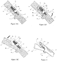
- FIGS. 6A to 6D are perspective views of an exemplary embodiment of the bicycle according to the invention.
- Such a configuration allows the deformable quadrilateral D to fold up as easily as in the other embodiments and, if the point S is sufficiently separated transversely from the median plane of the bicycle, the assembly has sufficient rigidity in the unfolded position, a once one of the joints (for example, the joint P4) is locked in rotation by a locking device (not shown). Indeed, the volume formed by the joints P1, P2, P3, P4 and the point S is then a stable pyramid.
- the figures 6A to 6D illustrate the complete folding kinematics of the bicycle.
- the front wheel 1 In the folded position, the front wheel 1 is positioned near and vis-à-vis the rear wheel 2 in the transverse direction, giving the bike a configuration and a volume similar to those of the embodiment of the figure 4C .
- This solution has the advantage of not having to position the crankset in a particular position or to remove the crankset before folding.
- the pin 32 extends in a direction substantially perpendicular to the median plane of the bicycle, without however touching the plate 17.
- the stop 33 and the pin 32 are respectively mounted fixed on the plate 17 and the rod 15.
- the figure 13 schematically illustrates the operation of this mechanism, in left side view.
- crank pin 32 In the unfolded position, that is to say in the position of use of the bicycle, the crank pin 32 is in a position 32a which does not interfere with the travel of the stop 33.
- the crankset can therefore turn freely around it. of its axis A17.
- Such a locking system makes it possible to avoid any interference of the pedal 18g with another part of the bicycle during the folding and unfolding operations, without prior manual intervention on the pedal of the bicycle and, in particular, without having to dismantle or fold up. the 18g pedal or the 19g crank. At most it can be recommended to the user, prior to folding, to check that the pedal 18g is in the low position, and if not, to rotate the latter with the foot until it reaches an adequate position.
- the figure 7A shows a right profile view of the folded bicycle, in a configuration similar to that of the figures 4C and 6D .
- the saddle 3 is pivotally mounted on a saddle support 20, and pivots around an articulation P5 formed by a pivot connection whose axis is perpendicular to that of the median plane of the bicycle.
- the handlebars 6 also have an articulation P6 whose axis I6 is oblique, in order to allow the handlebars 6 to switch to the left side of the bike, so as not to be hampered by the plate 17.
- the handlebar 6 In fully folded position ( figure 7B ), the handlebar 6 is folded in a plane substantially parallel to that of the front wheel 1.
- the saddle 3 can for its part be positioned between the front 1 and rear 2 wheels, by rotating the seat post 4 to the left if necessary. 'inside the saddle bar 5.
- the saddle 3 and the handlebars 6 are thus folded inside the volume delimited by the front 1 and rear 2 wheels.
- the figures 9A to 9D illustrate, in perspective, the folding sequence of another example of a folding bicycle according to the invention comprising a front wheel 1, a rear wheel 2 and a frame.
- the frame comprises a front frame part on which the front wheel 1 is mounted, via a pivoting fork 7, and a rear frame part A on which the rear wheel 2 is mounted,
- the rear frame part A comprises at least one seat stay 8, at least a lower bar 9 and a saddle bar 5.
- the front frame part comprises an upper bar 10, an upper portion 5A of the saddle bar 5, a bar junction 30 and a slash 11.
- the upper portion 5A of the saddle bar, the upper bar 10, the oblique bar 11 and the junction bar 30 are connected to each other, in this order, by joints P1 to P4 so as to form an articulated quadrilateral D deformable between a folded position and an unfolded position.
- the articulated quadrilateral D is configured such that, by deforming to its folded position, the bicycle can be folded lengthwise until the front wheel 1 comes to overlap with the rear wheel 2 in a direction cross section of the bike.
- This example of a bicycle therefore differs from that of the preceding figures in that its frame comprises an additional structural element, namely the junction bar 30, and in that the oblique bar 11 is not formed by a lower oblique rod. and an upper oblique rod articulated between them.
- the articulation P4 is on the contrary provided on the saddle bar 5 to connect the upper portion 5A of the saddle bar to the junction bar 30.
Description
Le présent exposé concerne un vélo pliant, c'est-à-dire un vélo déformable entre une position dépliée dans laquelle le vélo est utilisable comme moyen de transport et une position pliée dans laquelle l'encombrement du vélo est moindre. Une fois plié, le vélo peut ainsi être rangé ou transporté plus facilement.The present disclosure relates to a folding bicycle, that is to say a bicycle which can be deformed between an unfolded position in which the bicycle can be used as a means of transport and a folded position in which the size of the bicycle is less. Once folded, the bike can be stored or transported more easily.
Il existe déjà de nombreux types de vélos pliants; voir, par exemple, les documents de brevet
Il existe néanmoins quelques vélos pliants de taille normale; on entend par là des vélos équipés de roues dont le diamètre est proportionné à la taille de l'utilisateur du vélo. Typiquement, selon les standards actuels, le diamètre de roue (plus précisément de pneu) recommandé pour un adulte de taille moyenne est compris entre 650 et 700 mm, i.e. entre 26 et 28 pouces. Cependant, la plupart de ces vélos sont en réalité davantage démontables que pliants, leur pliage nécessitant de désassembler tout ou partie du cadre et/ou de démonter une ou plusieurs roues. C'est le cas, par exemple, du vélo pliant objet du document de brevet
Ces vélos ne sont donc pas satisfaisants car les opérations nécessaires à leur pliage sont complexes et leur cadre peut manquer de rigidité une fois assemblé.These bikes are therefore not satisfactory because the operations required for their folding are complex and their frame may lack rigidity once assembled.
Il existe donc un besoin pour un nouveau type de vélo pliant, de taille normale, dont les opérations de pliage et de dépliage soient simples et ne nécessitent pas de démonter une partie du cadre ou les roues du vélo.There is therefore a need for a new type of folding bicycle, of normal size, the folding and unfolding operations of which are simple and do not require removing part of the frame or the wheels of the bicycle.
L'invention concerne un vélo pliant selon les revendications indépendantes 1 et 2 annexées. Des modes de réalisation particuliers sont définis par les revendications dépendantes.The invention relates to a folding bicycle according to the appended
Un tel vélo pliant comprend une roue avant, une roue arrière et un cadre. Le cadre comprend une partie de cadre avant sur laquelle est montée la roue avant, par l'intermédiaire d'une fourche pivotante, et une partie de cadre arrière sur laquelle est montée la roue arrière. La partie de cadre avant comprend une barre supérieure, une barre de selle et une barre oblique. La barre de selle fait également partie de la partie de cadre arrière. La partie de cadre arrière peut comprendre au moins un hauban, au moins une barre inférieure et la barre de selle.Such a folding bicycle includes a front wheel, a rear wheel and a frame. The frame comprises a front frame part on which the front wheel is mounted, via a pivoting fork, and a rear frame part on which the rear wheel is mounted. The front frame part includes a top bar, a saddle bar and a slash. The seat bar is also part of the rear frame part. The rear frame portion may include at least one seat stay, at least one lower bar, and the saddle bar.
Selon un premier mode de réalisation, la barre oblique comprend une tige oblique supérieure et une tige oblique inférieure. La tige oblique inférieure, la tige oblique supérieure, la barre supérieure et la barre de selle sont reliées entre elles par des articulations, dans cet ordre, de manière à former un quadrilatère articulé déformable entre une position pliée et une position dépliée. Le quadrilatère articulé déformable est configuré de telle sorte que, en se déformant vers sa position pliée, le vélo se plie dans le sens de la longueur, les roues avant et arrière s'écartant transversalement l'une de l'autre tout en se rapprochant dans le sens de la longueur jusqu'à ce que la roue avant vienne se superposer à la roue arrière suivant une direction transversale du vélo.According to a first embodiment, the oblique bar comprises an upper oblique rod and a lower oblique rod. The lower oblique rod, the upper oblique rod, the upper bar and the saddle bar are interconnected by joints, in that order, so as to form a deformable hinged quadrilateral between a folded position and an unfolded position. The deformable hinged quadrilateral is configured such that, on deforming to its folded position, the bicycle folds lengthwise with the front and rear wheels moving transversely apart from each other while moving closer together lengthwise until the front wheel is superimposed on the rear wheel in a transverse direction of the bicycle.
Selon un deuxième mode de réalisation, la partie de cadre avant comprend une barre supérieure, une portion de la barre de selle, une barre de jonction et une barre oblique. La barre supérieure, la portion de la barre de selle, la barre de jonction et la barre oblique sont reliées entre elles, dans cet ordre, par des articulations de manière à former un quadrilatère articulé déformable entre une position pliée et une position dépliée. Le quadrilatère articulé déformable est configuré de telle sorte que, en se déformant vers sa position pliée, le vélo se plie dans le sens de la longueur, les roues avant et arrière s'écartant transversalement l'une de l'autre tout en se rapprochant dans le sens de la longueur jusqu'à ce que la roue avant vienne se superposer à la roue arrière suivant une direction transversale du vélo.According to a second embodiment, the front frame part comprises an upper bar, a portion of the saddle bar, a junction bar and an oblique bar. The top bar, the saddle bar portion, the junction bar and the slash are connected together, in that order, by hinges so as to form a deformable hinged quadrilateral between a folded position and an unfolded position. The deformable hinged quadrilateral is configured such that, on deforming to its folded position, the bicycle folds lengthwise with the front and rear wheels moving transversely apart from each other while moving closer together lengthwise until the front wheel is superimposed on the rear wheel in a transverse direction of the bicycle.
Ainsi, lorsque le vélo est en position pliée, la roue avant est superposée à la roue arrière suivant une direction transversale du vélo. En d'autres termes, la roue avant et la roue arrière sont disposées sensiblement l'une en face de l'autre suivant la direction transversale du vélo, étant entendu que ces roues peuvent être légèrement décalées l'une par rapport à l'autre suivant une direction perpendiculaire à la direction transversale, sans sortir du cadre de l'invention.Thus, when the bicycle is in the folded position, the front wheel is superimposed on the rear wheel in a transverse direction of the bicycle. In other words, the front wheel and the rear wheel are arranged substantially opposite each other in the transverse direction of the bicycle, it being understood that these wheels may be slightly offset from one another. in a direction perpendicular to the transverse direction, without departing from the scope of the invention.
Dans le présent exposé, la longueur du vélo est considérée entre l'extrémité avant de la roue avant et l'extrémité arrière de la roue arrière du vélo. La direction longitudinale du vélo est la direction dans le sens de longueur du vélo. La direction longitudinale correspond donc à la direction avant-arrière du vélo lorsque celui-ci est en position dépliée, l'avant et l'arrière étant définis par rapport au sens de déplacement normal du vélo lorsque celui-ci est utilisé comme moyen de transport.In the present disclosure, the length of the bicycle is considered between the front end of the front wheel and the rear end of the rear wheel of the bicycle. The longitudinal direction of the bicycle is the direction along the length of the bicycle. The direction longitudinal therefore corresponds to the front-rear direction of the bicycle when the latter is in the unfolded position, the front and the rear being defined with respect to the normal direction of travel of the bicycle when the latter is used as a means of transport.
La hauteur du vélo est considérée suivant la verticale lorsque le vélo repose sur ses roues, en position dépliée, sur une surface horizontale.The height of the bicycle is considered vertically when the bicycle rests on its wheels, in the unfolded position, on a horizontal surface.
On appelle "plan médian" du vélo le plan médian de la roue arrière du vélo. Lorsque le vélo est déplié et que ses roues avant et arrière sont alignées, les roues avant et arrière se trouvent dans le plan médian et l'axe longitudinal du vélo est contenu dans ce plan.The median plane of the rear wheel of the bicycle is called the “midplane” of the bicycle. When the bicycle is unfolded and its front and rear wheels are aligned, the front and rear wheels are in the midplane and the longitudinal axis of the bicycle is contained in this plane.
La direction transversale est la direction perpendiculaire au plan médian du vélo.The transverse direction is the direction perpendicular to the midplane of the bicycle.
Le fait que les roues avant et arrière soient superposées en position pliée suivant la direction transversale permet de limiter l'encombrement du vélo en position pliée tout en conservant des roues de taille normale, i.e. de diamètre proportionné à la taille de l'utilisateur du vélo. Le confort et la stabilité du vélo lors de son utilisation en position dépliée sont ainsi préservés et, en position pliée, le vélo peut être rangé facilement (par exemple dans un appartement, une cave, sur un balcon, etc.) et transporté facilement (par exemple dans un coffre de voiture, dans les transports en commun, etc.).The fact that the front and rear wheels are superimposed in the folded position in the transverse direction makes it possible to limit the size of the bicycle in the folded position while keeping the wheels of normal size, ie of diameter proportional to the size of the user of the bicycle. . The comfort and stability of the bicycle when using it in the unfolded position are thus preserved and, in the folded position, the bicycle can be easily stored (for example in an apartment, a cellar, on a balcony, etc.) and easily transported ( for example in a car trunk, in public transport, etc.).
En outre, la déformation du quadrilatère articulé étant possible sans avoir à démonter une partie du cadre ou une roue du vélo, le pliage du vélo se fait simplement et rapidement.In addition, the deformation of the articulated quadrilateral being possible without having to dismantle part of the frame or a wheel of the bicycle, the folding of the bicycle is done simply and quickly.
Ledit quadrilatère articulé est délimité par les quatre articulations précitées qui forment les quatre sommets du quadrilatère. Les quatre côtés du quadrilatère sont, quant à eux, formés par les éléments qui relient les articulations entre elles. Dans le premier mode de réalisation précité, les quatre côtés sont formés essentiellement par la tige oblique inférieure, la tige oblique supérieure, la barre supérieure et la barre de selle, respectivement. De même, dans le deuxième mode de réalisation précité, les quatre côtés sont formés essentiellement par la barre supérieure, la portion supérieure de la barre de selle, la barre de jonction et la barre oblique, respectivement. Les tiges et barres précitées sont généralement essentiellement rectilignes mais elles ne le sont pas nécessairement. La notion de quadrilatère ne doit donc, à cet égard, pas être interprétée au sens strict. Par exemple, ces tiges et barres peuvent être courbes ou en forme de lignes brisées sans sortir du cadre de l'invention.Said articulated quadrilateral is delimited by the four aforementioned articulations which form the four vertices of the quadrilateral. The four sides of the quadrilateral are, in turn, formed by the elements that connect the joints between them. In the above-mentioned first embodiment, the four sides are formed essentially by the lower oblique rod, the upper oblique rod, the upper bar and the saddle bar, respectively. Likewise, in the aforementioned second embodiment, the four sides are formed essentially by the upper bar, the upper portion of the saddle bar, the junction bar and the slash, respectively. The aforementioned rods and bars are generally essentially straight, but they are not necessarily so. The concept of a quadrilateral should therefore not be interpreted in the strict sense in this regard. By example, these rods and bars may be curved or in the form of broken lines without departing from the scope of the invention.
Selon l'invention, les articulations sont des liaisons pivot. Ces liaisons structurellement simples permettent de guider en rotation les quatre côtés du quadrilatère articulé déformable en n'autorisant qu'une seule rotation autour de l'axe de la liaison. Le pliage du vélo est facilité par ce guidage. Le vélo peut ainsi être plié de manière souple, rapide et intuitive.According to the invention, the joints are pivot links. These structurally simple connections make it possible to guide the four sides of the deformable articulated quadrilateral in rotation while allowing only one rotation around the axis of the connection. Folding the bicycle is facilitated by this guidance. The bike can therefore be folded flexibly, quickly and intuitively.
Selon l'invention, les articulations sont des liaisons pivot et les axes de ces liaisons sont sécants en un même point.According to the invention, the joints are pivot links and the axes of these links intersect at the same point.
Dans d'autres exemples de vélos pliants ne faisant pas partie de l'invention, les axes des liaisons sont parallèles entre eux. Dans ce cas, les axes des liaisons sont de préférence inclinés d'un même angle par rapport à la direction transversale du vélo. Les axes des liaisons peuvent être horizontaux lorsque le vélo est déplié et repose sur une surface horizontale.In other examples of folding bicycles not forming part of the invention, the axes of the links are mutually parallel. In this case, the axes of the connections are preferably inclined at the same angle with respect to the transverse direction of the bicycle. The axes of the links can be horizontal when the bicycle is unfolded and rests on a horizontal surface.
Dans certains modes de réalisation, la partie de cadre arrière est indéformable. Ceci permet d'améliorer la stabilité du vélo lors de son utilisation.In some embodiments, the rear frame portion is dimensionally stable. This improves the stability of the bicycle during use.
Dans certains modes de réalisation, le vélo comprend un système de verrouillage pour verrouiller le quadrilatère articulé dans sa position dépliée. En fonction de la configuration retenue pour le quadrilatère articulé, le système de verrouillage peut être prévu entre la tige oblique inférieure et la tige oblique supérieure, ou entre la portion de la barre de selle et la barre de jonction.In some embodiments, the bicycle includes a locking system for locking the articulated quadrilateral in its unfolded position. Depending on the configuration chosen for the articulated quadrilateral, the locking system can be provided between the lower oblique rod and the upper oblique rod, or between the portion of the saddle bar and the junction bar.
Le système de verrouillage peut comprendre, par exemple, une pince ou un collier de serrage maintenu par une vis, ou un système à crochet actionné par un levier. Dans certains modes de réalisation, le système de verrouillage comprend un pêne monté coulissant à l'intérieur d'une des tiges obliques, entre une position sortie et une position rétractée, et une gâche aménagée à l'intérieur de l'autre tige oblique et coopérant avec le pêne en position sortie pour empêcher la rotation relative des tiges obliques autour de l'articulation.The locking system may include, for example, a clamp or a clamp held by a screw, or a hook system operated by a lever. In certain embodiments, the locking system comprises a bolt slidably mounted inside one of the oblique rods, between an extended position and a retracted position, and a keeper arranged inside the other oblique rod and cooperating with the bolt in the extended position to prevent the relative rotation of the oblique rods around the joint.
Dans certains modes de réalisation, l'une des tiges obliques présente un prolongement s'étendant axialement au-delà de l'articulation, tandis que l'autre tige présente une découpe dont la forme est complémentaire de celle du prolongement, et le pêne coulisse axialement à l'intérieur du prolongement. Cette configuration permet d'assurer un meilleur verrouillage du quadrilatère articulé dans sa position dépliée.In some embodiments, one of the oblique rods has an extension extending axially beyond the joint, while the other rod has a cutout whose shape is complementary to that of the extension, and the bolt slides axially inside the extension. This configuration makes it possible to ensure better locking of the articulated quadrilateral in its unfolded position.
Dans certains modes de réalisation, le système de verrouillage comprend un levier de déverrouillage monté sur la même tige oblique que le pêne et coopérant avec le pêne pour entraîner celui-ci vers sa position rétractée, et ainsi autoriser la rotation des tiges obliques l'une par rapport à l'autre.In certain embodiments, the locking system comprises an unlocking lever mounted on the same oblique rod as the bolt and cooperating with the bolt to drive the latter towards its retracted position, and thus allow the rotation of the oblique rods one. compared to each other.
Dans certains modes de réalisation, le système de verrouillage comprend un verrou monté mobile dans ledit prolongement, entre une position de blocage du pêne et une position de déblocage du pêne. En référence à l'axe central de la tige oblique, le verrou est mobile en translation latéralement mais pas axialement. Un pion est prévu en face du verrou, sur face latérale de la découpe, de sorte que le pion vient appuyer sur le verrou pour débloquer le pêne lorsque les tiges obliques sont dépliées pour être alignées. Une telle configuration permet de débloquer le pêne, et ainsi de verrouiller le quadrilatère articulé, facilement et rapidement lors du dépliage du vélo.In certain embodiments, the locking system comprises a lock mounted movably in said extension, between a locking position of the bolt and an unlocking position of the bolt. With reference to the central axis of the oblique rod, the lock is movable in translation laterally but not axially. A pin is provided in front of the lock, on the side face of the cutout, so that the pin comes to press on the lock to unlock the bolt when the oblique rods are unfolded to be aligned. Such a configuration makes it possible to unlock the bolt, and thus to lock the articulated quadrilateral, easily and quickly when unfolding the bicycle.
Dans certains modes de réalisation, le vélo comprend un système de blocage pour bloquer le pédalier du vélo dans une position particulière lors du pliage ou du dépliage du vélo. En particulier, le pédalier peut comprendre un plateau de pédalier tournant autour d'un axe et le système de blocage peut comprendre un pion fixé sur la tige oblique inférieure à proximité du plateau; et une butée fixée sur la face intérieure du plateau. En position dépliée, le pion n'interfère pas avec la course de la butée et le plateau peut donc tourner librement autour de son axe. Lors du pliage, lorsque la tige oblique inférieure pivote par rapport à la barre de selle et se rapproche de celle-ci, le pion se rapproche de l'axe du plateau et coupe la course de la butée. Le plateau du pédalier ne peut alors plus tourner librement.In some embodiments, the bicycle includes a locking system for locking the bicycle crankset in a particular position when folding or unfolding the bicycle. In particular, the crankset may include a bottom bracket rotating around an axis and the locking system may include a pin fixed on the lower oblique rod near the plate; and a stopper fixed on the inside face of the plate. In the unfolded position, the pin does not interfere with the travel of the stopper and the plate can therefore rotate freely around its axis. During folding, when the lower oblique rod pivots with respect to the saddle bar and approaches the latter, the pin approaches the axis of the plate and cuts the stroke of the stop. The bottom bracket can then no longer turn freely.
Les caractéristiques et avantages précités, ainsi que d'autres, apparaîtront à la lecture de la description détaillée qui suit, d'exemples de réalisation du vélo pliant proposé. Cette description détaillée fait référence aux dessins annexés.The aforementioned characteristics and advantages, as well as others, will become apparent on reading the following detailed description of exemplary embodiments of the proposed folding bicycle. This detailed description refers to the accompanying drawings.
Les dessins annexés sont schématiques et ne sont pas à l'échelle, ils visent avant tout à illustrer les principes de l'invention.The accompanying drawings are diagrammatic and are not to scale, they are intended above all to illustrate the principles of the invention.
Sur ces dessins, d'une figure (FIG) à l'autre, des éléments (ou parties d'élément) identiques sont repérés par les mêmes signes de référence.
- La
figure 1 est une vue de profil, schématique, d'un vélo classique selon l'art antérieur. - Les
figures 2A à 2C sont des vues de profil, schématiques, de la séquence de pliage d'un exemple de vélo selon l'invention. - La
figure 3 est une vue de dessus d'un autre exemple de vélo. - Les
figures 4A à 4C illustrent, en perspective, la séquence de pliage du vélo de lafigure 3 . - La
figure 5 illustre le vélo de lafigure 3 en position pliée, vu de face selon la flèche V de lafigure 4C . - Les
figures 6A à 6D illustrent, en perspective, la séquence de pliage d'un exemple de vélo pliant selon l'invention. - Les
figures 7A et 7B montrent, en vue de profil, un vélo dans une position repliée similaire à celles desfigures 4C et6D . - La
figure 8 représente un exemple de système de verrouillage pour verrouiller un vélo dans sa position dépliée. - Les
figures 9A à 9D illustrent, en perspective, la séquence de pliage d'un autre exemple de vélo pliant selon l'invention. - Les
figures 10A à 10C représentent un deuxième exemple de système de verrouillage pour verrouiller un vélo dans sa position dépliée. - La
figure 11 est une vue en perspective de ce deuxième exemple de système de verrouillage, en position déverrouillée. - Les
figures 12A et 12B représentent en perspective le pédalier d'un vélo pliable et un système de blocage du pédalier, lorsque le vélo est en position dépliée et pliée, respectivement. - La
figure 13 représente schématiquement, en vue de coté, le pédalier et le système de blocage desfigures 12A et 12B .
- The
figure 1 is a side view, schematic, of a conventional bicycle according to the prior art. - The
figures 2A to 2C are profile views, schematic, of the folding sequence of an example of a bicycle according to the invention. - The
figure 3 is a top view of another example of a bicycle. - The
figures 4A to 4C illustrate, in perspective, the sequence of folding the bicycle of thefigure 3 . - The
figure 5 illustrates the bike of thefigure 3 in folded position, seen from the front according to arrow V of thefigure 4C . - The
figures 6A to 6D illustrate, in perspective, the folding sequence of an example of a folding bicycle according to the invention. - The
figures 7A and 7B show, in profile view, a bicycle in a folded position similar to those offigures 4C and6D . - The
figure 8 shows an example of a locking system for locking a bicycle in its unfolded position. - The
figures 9A to 9D illustrate, in perspective, the folding sequence of another example of a folding bicycle according to the invention. - The
figures 10A to 10C show a second example of a locking system for locking a bicycle in its unfolded position. - The
figure 11 is a perspective view of this second example of a locking system, in the unlocked position. - The
figures 12A and 12B represent in perspective the crankset of a folding bicycle and a crank locking system, when the bicycle is in the unfolded and folded position, respectively. - The
figure 13 schematically shows, in side view, the crankset and the locking systemfigures 12A and 12B .
Des exemples de réalisation sont décrits en détail ci-après, en référence aux dessins annexés. Ces exemples illustrent les caractéristiques et les avantages de l'invention. Il est toutefois rappelé que l'invention ne se limite pas à ces exemples.Exemplary embodiments are described in detail below, with reference to the accompanying drawings. These examples illustrate the characteristics and advantages of the invention. It is however recalled that the invention is not limited to these examples.
Dans la présente demande, sauf précision contraire, les directions horizontale et verticale sont considérées en référence à la position dépliée du vélo lorsque celui-ci repose, dans des conditions normales d'utilisation, sur une surface horizontale. Le haut et le bas sont définis suivant la direction verticale. L'avant et l'arrière, la droite et la gauche, sont définis par rapport au sens de roulement normal du vélo.In the present application, unless otherwise specified, the horizontal and vertical directions are considered with reference to the unfolded position of the bicycle when the latter rests, under normal conditions of use, on a horizontal surface. The top and bottom are defined in the vertical direction. The front and rear, right and left, are defined in relation to the normal rolling direction of the bicycle.
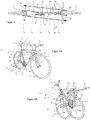
La
- une roue avant 1 et une roue arrière 2 ;
une selle 3 montée sur une tige de selle 4, elle-même montée sur une barre de selle 5;une fourche 7 montée pivotante sur le cadre du vélo et sur laquelle est fixée la roue avant 1, etun guidon 6 relié à la fourche 7 et permettant de fait pivoter celle-ci.
- a
front wheel 1 and arear wheel 2; - a
saddle 3 mounted on asaddle post 4, itself mounted on asaddle bar 5; - a
fork 7 pivotally mounted on the frame of the bicycle and on which thefront wheel 1 is fixed, and - a
handlebar 6 connected to thefork 7 and allowing the latter to pivot.
La barre de selle 5 est, typiquement, un tube à l'intérieur duquel la tige de selle 4 est montée coulissante, de sorte que la selle 3 puisse être réglée en hauteur.The
En outre, le vélo comporte un cadre comprenant une partie de cadre arrière A (parfois appelée triangle arrière) et une partie de cadre avant C (parfois appelée triangle avant ou triangle central).In addition, the bicycle has a frame comprising a rear frame part A (sometimes called a rear triangle) and a front frame part C (sometimes called a front triangle or central triangle).
Le partie de cadre arrière A est formé par la barre de selle 5, au moins un hauban 8 et au moins une barre inférieure 9 (parfois appelée barre de chaîne). En général, sauf pour les modèles de vélo dits "monobras", le hauban 8 et la barre inférieure 9 sont doublés (i.e. il existe deux haubans et deux barres inférieures) et situés de part et d'autre de la roue arrière 2. Dans ce cas, les haubans gauche et droit sont respectivement notés 8g et 8d, et les barres inférieures gauche et droite sont respectivement notées 9g et 9d.The rear frame part A is formed by the
De même, la fourche 7, si elle n'est pas monobras, comporte un bras de fourche gauche 7g et un bras de fourche droit 7d.Likewise, the
Le partie de cadre avant C est formée par la barre de selle 5, une barre supérieure 10 (parfois appelée barre horizontale) et une barre oblique 11. Un tube de direction 12 est fixé sur la partie de cadre avant C, au niveau du sommet avant de cette partie. La fourche 7 et le guidon 6 pivotent à l'intérieur du tube de direction.The front frame part C is formed by the
En outre, le vélo de la
La
Sur ce vélo, par contraste avec le vélo de la
- le barre de selle 5, qui relie les articulations P1 et P3 ;
- le barre horizontale 10, qui relie les articulations P1 et P2 ;
- une
tige oblique supérieure 14, qui relie les articulations P2 et P4 ; et - une
tige oblique inférieur 15, qui relie les articulations P3 et P4.
- the
saddle bar 5, which connects the joints P1 and P3; - the
horizontal bar 10, which connects the joints P1 and P2; - an
upper oblique rod 14, which connects the joints P2 and P4; and - a
lower oblique rod 15, which connects the joints P3 and P4.
Sur ce vélo, par contraste avec le vélo de la
Les barres et tiges 5, 10, 14, 15 qui forment les quatre côtés du quadrilatère articulé D sont rigides.The bars and
Dans l'exemple représenté, le tube de direction 12 fait partie intégrante de la tige oblique supérieure 14 et forme l'extrémité supérieure de celle-ci. L'articulation P2 relie ce tube de direction 12 à la barre horizontale 10. Le tube de direction 12 pourrait toutefois être relié différemment à la tige oblique supérieure 14 ou à la barre horizontale 10. Par exemple, le tube de direction peut faire partie intégrante de la barre horizontale 10 et former l'extrémité avant de celle-ci. Dans ce cas, l'articulation P2 peut relier le tube de direction 12 à la tige oblique supérieure 14.In the example shown, the steering
L'articulation P3 se situe à proximité de l'axe du boîtier de pédalier 13 mais n'est pas nécessairement positionnée sur cet axe.The articulation P3 is located near the axis of the
Le cadre du vélo de la
La partie de cadre avant formant le quadrilatère articulé D comprend la barre supérieure 10, la barre de selle 5 et la barre oblique formée par la tige oblique inférieure 15 et la tige oblique supérieure 14. La partie de cadre arrière A comprend le ou les haubans 8, la ou les barres inférieures 9 et la barre de selle 5.The front frame part forming the articulated quadrilateral D comprises the
Dans sa position dépliée représentée sur la
Un quadrilatère articulé déformable relié par des articulations n'offrant qu'un seul degré de liberté en rotation (rotation seule ou conjuguée à une translation) offre l'avantage de pouvoir se plier et se déplier facilement sans avoir à déconnecter l'un de ses éléments.A deformable articulated quadrilateral connected by joints offering only one degree of freedom in rotation (rotation alone or combined with a translation) offers the advantage of being able to fold and unfold easily without having to disconnect one of its elements.
En outre, il suffit de bloquer l'une des articulations pour que le quadrilatère devienne indéformable. Aussi, un système de verrouillage est prévu pour bloquer une des articulations et verrouiller le quadrilatère articulé dans sa position dépliée. Ainsi, en position dépliée, une fois que la partie de cadre avant est verrouillée, le vélo possède une rigidité sensiblement équivalente à celle d'un vélo classique comme celui de la
Un exemple de système de verrouillage 40 est représenté sur la
Les
En référence aux
un pêne 21 monté coulissant à l'intérieur de la tigeoblique inférieure 15, entre une position sortie et une position rétractée ;une gâche 23, aménagée à l'intérieur de la tigeoblique supérieure 14, et coopérant avec le pêne 21 en position sortie pour bloquer l'articulation P4, i.e. pour empêcher la rotation relative des tiges obliques 14 et 15 autour de l'articulation P4 ; et- un levier de déverrouillage 24 monté sur la tige oblique inférieure 15 et coopérant avec le pêne 21 pour entraîner celui-ci vers sa position rétractée et débloquer l'articulation P4, et ainsi autoriser la rotation des tiges obliques l'une par rapport à l'autre.
- a
bolt 21 slidably mounted inside thelower oblique rod 15, between an extended position and a retracted position; - a
keeper 23, fitted inside theupper oblique rod 14, and cooperating with thebolt 21 in the extended position to block the joint P4, ie to prevent the relative rotation of theoblique rods - an unlocking
lever 24 mounted on thelower oblique rod 15 and cooperating with thebolt 21 to drive the latter towards its retracted position and unlock the joint P4, and thus allow the rotation of the oblique rods relative to the other.
L'une des tiges, dans l'exemple la tige 15, présente un prolongement 15a s'étendant axialement au-delà de l'articulation P4, tandis que l'autre tige 14 présente une découpe 14a dont la forme est complémentaire de celle du prolongement 15a. Lors du dépliage du vélo, le prolongement 15a vient se loger dans la découpe 14a. Le pêne 21 est logé au moins en partie dans le prolongement 15a et coulisse axialement à l'intérieur de celui-ci, tandis que la gâche 23 est ménagée au niveau de la découpe 14a. En position sortie, le pêne 21 fait saillie à l'extrémité libre du prolongement 15a. Ainsi, la zone d'engagement du pêne 21 dans la gâche 23 est déportée axialement par rapport à l'articulation P4. Une telle configuration permet d'obtenir un meilleur verrouillage.One of the rods, in the
En position sortie, le pêne 21 est engagé ou enfoncé dans la gâche 23 (cf.
Un verrou 27 peut être monté dans la tige oblique inférieure 15 pour maintenir le pêne 21 dans sa position retractée (cf.
Une rainure 31 peut être ménagée dans la face latérale du pêne 21 située à l'opposé de l'encoche 29 pour recevoir la première extrémité 27a du verrou. En position de déblocage, la première extrémité 27a du verrou est engagée dans la rainure 31, comme représenté sur la
Le levier 24 est monté pivotant sur la tige oblique inférieure 15 autour d'un axe 25 et coopère avec une butée 22 du peine 21. Ce levier 24 permet d'agir contre la force de rappel exercée par le ressort 26 sur le pêne 21. Pour effectuer le déverrouillage (
Le levier 24 comporte également un ou plusieurs poussoirs 24a. Lors du déverrouillage, lorsque le levier 24 est soulevé, le ou les poussoirs 24a appuient sur la tige oblique supérieure 14, l'obligeant à s'écarter de la tige oblique inférieure 15 en pivotant autour de l'articulation P4. Ainsi, lorsque le levier 24 est soulevé et simultanément au coulissement du pêne 21, le pion 50 cesse d'appuyer sur la première extrémité 27a du verrou 27, ce qui rend possible le déplacement latéral du verrou 27 et permet à la deuxième extrémité 27b de s'engager dans l'encoche 29. Le verrou 27 maintient alors le pêne 21 dans sa position rétractée.The
Pour poursuivre le pliage du vélo (
Inversement, lors du dépliage du vélo, au moment où les tiges obliques 14 et 15 pivotent l'une par rapport à l'autre et atteignent la position relative illustrée sur la
La
Bien entendu, les formes des tiges 14 et 15 pourraient être inversées, i.e. le pêne 21 pourrait être monté sur la tige oblique supérieure 14 et la gâche 23 être ménagée dans la tige oblique inférieure 15.Of course, the shapes of the
Pour amorcer le pliage du vélo de la
En position pliée (
Comme représenté sur la
On obtient ainsi un vélo de taille normale au pliage simple et fiable, ne nécessitant pas de démonter une partie du cadre ou une roue, ayant une structure rigide en position dépliée et offrant un faible encombrement en position pliée.A normal-size bicycle is thus obtained which is simple and reliable to fold, does not require dismantling a part of the frame or a wheel, having a rigid structure in the unfolded position and offering a small footprint in the folded position.
On notera toutefois que le pliage décrit en référence aux
Il est donc nécessaire de prévoir une configuration particulière pour les articulations P1, P2, P3 et P4 afin de permettre, lors du pliage, à la roue avant 1 de se décaler sur le côté (i.e. transversalement) par rapport à la roue arrière 2.It is therefore necessary to provide a particular configuration for the joints P1, P2, P3 and P4 in order to allow, during folding, the
Selon une configuration possible mais ne faisant pas partie de l'invention, les articulations P1, P2, P3 et P4 sont des liaisons hélicoïdales, c'est-à-dire des liaisons offrant une mobilité selon des mouvements de rotation et de translation conjugués, dont les axes sont perpendiculaires au plan médian du vélo, et dont les sens de rotation ainsi que les pas respectifs sont calculés de sorte que, lors du pliage, le plan du cadre avant et de la roue avant 1 s'écarte transversalement de celui de la partie de cadre arrière A et de la roue arrière 2. D'autres configurations possibles, utilisant des articulations de structure plus simple et, généralement, plus robuste qu'une liaison hélicoïdale, sont décrites en référence aux
La
Dans cet exemple ne faisant pas partie de l'invention, les articulations P1, P2, P3 et P4 sont des liaisons pivot dont les axes, nommés respectivement I1, I2, I3 et I4, sont parallèles et inclinés d'un même angle A1 par rapport à la direction transversale T du vélo.In this example not forming part of the invention, the joints P1, P2, P3 and P4 are pivot links whose axes, respectively called I1, I2, I3 and I4, are parallel and inclined at the same angle A1 by relative to the transverse direction T of the bicycle.
Dans l'exemple représenté, les axes I1, I2, I3 et I4 sont inclinés d'un angle A1 dans le sens des aiguilles d'une montre (en vue du dessus) ou vers l'arrière sur la partie droite du vélo.In the example shown, the axes I1, I2, I3 and I4 are inclined at an angle A1 in the direction of clockwise (viewed from above) or towards the rear on the right part of the bicycle.
Cette configuration permet, lors du pliage, si l'on considère la barre supérieure 10 comme fixe, de faire pivoter la partie avant du vélo, notamment la roue avant 1, vers l'arrière autour de l'articulation P2 en s'écartant transversalement, sur la gauche sur la
On notera que le vélo est équipé, en plus d'un boîtier de pédalier 13, d'un plateau 17 situé en général sur la droite du vélo.It will be noted that the bicycle is equipped, in addition to a
En outre, dans cet exemple, le tube de direction 12 est relié fixement à la tige oblique supérieure 14, par l'intermédiaire d'un bras 16 permettant de déporter vers l'avant le tube de direction 12 par rapport à la tige oblique supérieure 14. Le tube de direction 12 pourrait toutefois être relié différemment à la tige oblique supérieure 14 ou à la barre horizontale 10 sans que ceci n'affecte le pliage ou le bon fonctionnement du vélo.In addition, in this example, the steering
Les
Au cours du pliage (
De même, la tige oblique inférieure 15, en pivotant autour de l'articulation P4, passe sur la droite de la roue avant 1, et en pivotant autour de l'articulation P3, passe sur la gauche de la barre de selle 5.Likewise, the
En position pliée (
Comme illustré sur la
L'angle A1 peut donc être ajusté afin de permettre un pliage sans encombre (
Sur les
Les
Cet exemple diffère de celui des
Dans l'exemple des
Une telle configuration permet au quadrilatère déformable D de se replier aussi facilement que dans les autres exemples de réalisation et, si le point S est suffisamment écarté transversalement du plan médian du vélo, l'ensemble dispose d'une rigidité suffisante en position dépliée, une fois que l'une des articulations (par exemple, l'articulation P4) est bloquée en rotation par un dispositif de verrouillage (non représenté). En effet, le volume formé par les articulations P1, P2, P3, P4 et le point S est alors une pyramide stable.Such a configuration allows the deformable quadrilateral D to fold up as easily as in the other embodiments and, if the point S is sufficiently separated transversely from the median plane of the bicycle, the assembly has sufficient rigidity in the unfolded position, a once one of the joints (for example, the joint P4) is locked in rotation by a locking device (not shown). Indeed, the volume formed by the joints P1, P2, P3, P4 and the point S is then a stable pyramid.
Pour cet exemple de réalisation, on a représenté sur les figures le pédalier complet du vélo, comportant :
- une pédale gauche 18g montée pivotante sur une manivelle gauche 19g, elle-même fixée au boîtier de pédalier 13 ;
- une pédale droite 18d montée pivotante sur une manivelle droite 19d, également fixée au boîtier de pédalier 13.
- a
left pedal 18g pivotally mounted on aleft crank 19g, itself fixed to thebottom bracket 13; - a
right pedal 18d pivotally mounted on aright crank 19d, also fixed to thebottom bracket 13.
Les
Au début du pliage (
Lorsque le pliage du vélo continue (
En position pliée, la roue avant 1 vient se positionner à proximité et en vis-à-vis de la roue arrière 2 suivant la direction transversale, en donnant au vélo une configuration et un volume similaires à ceux de l'exemple de réalisation de la
Toutefois, un système peut être prévu pour réduire au maximum le risque d'interférence entre une pédale, ici la pédale gauche 18g, et une autre partie du vélo lors des opérations de pliage et de dépliage. Ainsi, le vélo peut comprendre un système permettant, au cours des opérations de pliage et de dépliage, de bloquer le pédalier dans une position particulière. En particulier, une des pédales, ici la pédale gauche 18g, peut être maintenue ou bloquée en position basse (par rapport au vélo en position dépliée), c'est-à-dire dans une position où la manivelle gauche 19g est dans une position sensiblement verticale et orientée vers le bas, tel qu'illustré sur les
un pion 32, fixé sur la tigeoblique inférieure 15, à proximité duplateau 17; etune butée 33, fixée sur la face intérieure duplateau 17.
- a
pin 32, fixed on thelower oblique rod 15, near theplate 17; and - a
stop 33, fixed on the inside face of theplate 17.
Le pion 32 s'étend dans une direction sensiblement perpendiculaire au plan médian du vélo, sans toutefois toucher le plateau 17. La butée 33 et le pion 32 sont respectivement montés fixes sur le plateau 17 et la tige 15.The
Lors du pliage du vélo (
La
En position dépliée, c'est-à-dire en position d'utilisation du vélo, le pion de pédalier 32 se trouve dans une position 32a qui n'interfère pas avec la course de la butée 33. Le pédalier peut donc tourner librement autour de son axe A17.In the unfolded position, that is to say in the position of use of the bicycle, the
Dès le début du pliage, lorsque la tige oblique inférieure 15 pivote autour de l'axe A3, le pion 32 se rapproche de l'axe A17, et coupe la course de la butée 33, i.e. lorsque le plateau tourne, la butée 33 vient contre le pion 32 et est bloquée dans son mouvement. En position pliée, le pion 32 se trouve dans la position 32b, représentée en pointillés sur la
Un tel système de blocage permet d'éviter toute interférence de la pédale 18g avec une autre partie du vélo lors des opérations de pliage et de dépliage, sans intervention manuelle préalable sur le pédalier du vélo et, en particulier, sans avoir à démonter ou replier la pédale 18g ou la manivelle 19g. Tout au plus il peut être recommandé à l'utilisateur, préalablement au pliage, de vérifier que la pédale 18g est en position basse, et dans le cas contraire, de faire tourner celle-ci avec le pied jusqu'à atteindre une position adéquate.Such a locking system makes it possible to avoid any interference of the
Afin de réduire encore l'encombrement du vélo plié, on peut prévoir des dispositifs complémentaires permettant de replier la selle 3 et le guidon 6.In order to further reduce the bulk of the folded bicycle, additional devices can be provided for folding the
La
La selle 3 est montée pivotante sur un support de selle 20, et pivote autour d'une articulation P5 formée par une liaison pivot dont l'axe est perpendiculaire à celui du plan médian du vélo.The
Le guidon 6 dispose également d'une articulation P6 dont l'axe I6 est oblique, afin de permettre au guidon 6 de basculer sur le côté gauche du vélo, pour ne pas être gêné par le plateau 17.The
En position totalement pliée (
Les
La partie de cadre arrière A comprend au moins un hauban 8, au moins une barre inférieure 9 et une barre de selle 5. La partie de cadre avant comprend une barre supérieure 10, une portion supérieure 5A de la barre de selle 5, une barre de jonction 30 et une barre oblique 11.The rear frame part A comprises at least one
La portion supérieure 5A de la barre de selle, la barre supérieure 10, la barre oblique 11 et la barre de jonction 30 sont reliées entre elles, dans cet ordre, par des articulations P1 à P4 de manière à former un quadrilatère articulé D déformable entre une position pliée et une position dépliée. Le quadrilatère articulé D est configuré de telle sorte que, en se déformant vers sa position pliée, le vélo peut être plié dans le sens de la longueur jusqu'à ce que la roue avant 1 vienne se superposer à la roue arrière 2 suivant une direction transversale du vélo.The upper portion 5A of the saddle bar, the
Cet exemple de vélo diffère donc de celui des figures précédentes en ce que son cadre comprend un élément de structure supplémentaire, à savoir la barre de jonction 30, et en ce que la barre oblique 11 n'est pas formée d'une tige oblique inférieure et d'une tige oblique supérieure articulées entre elles. L'articulation P4 est au contraire prévue sur la barre de selle 5 pour relier la portion supérieure 5A de la barre de selle à la barre de jonction 30. Les explications données pour les exemples précédents, relatives à la configuration des articulations et, plus généralement, du quadrilatère articulé D restent néanmoins valables. Ces explications ne sont donc pas répétées ici par souci de concision.This example of a bicycle therefore differs from that of the preceding figures in that its frame comprises an additional structural element, namely the
Les modes ou exemples de réalisation décrits dans le présent exposé sont donnés à titre illustratif et non limitatif, une personne du métier pouvant facilement, au vu de cet exposé, modifier ces modes ou exemples de réalisation, ou en envisager d'autres, tout en restant dans la portée de l'invention définie par les revendications annexées.The embodiments or embodiments described in the present disclosure are given by way of illustration and are not limited to, a person skilled in the art being able easily, in view of this disclosure, to modify these embodiments or examples of embodiment, or to envisage others, while at the same time remaining within the scope of the invention defined by the appended claims.
Claims (13)
- A folding bicycle comprising a front wheel (1), a rear wheel (2) and a frame wherein,
the frame comprises a front frame portion on which the front wheel is mounted, via a pivoting fork (7), and a rear frame portion (A) on which the rear wheel is mounted,
the front frame portion comprises an upper bar (10), a seat bar (5) and an oblique bar (11),
the rear frame portion comprises at least one seat stay (8), at least one lower bar (9) and the seat bar (5), and wherein,
the oblique bar (11) comprises an upper oblique rod (14) and a lower oblique rod (15),
the lower oblique rod (15), the upper oblique rod (14), the upper bar (10) and the seat bar (5) are interconnected by joints (P1, P2, P3, P4), in this order, so as to form an articulated quadrilateral (D) deformable between a folded position and an unfolded position,
the articulated quadrilateral (D) is configured in such a way that, when deforming towards its folded position, the bicycle folds in the longitudinal direction, the front and rear wheels move transversely away from each other while moving towards each other in the longitudinal direction until the front wheel (1) comes to overlap with the rear wheel (2) in a transverse direction of the bicycle, and
the joints (P1, P2, P3, P4) are revolute joints and axes (11, 12, 13, 14) of these joints intersect at a same point. - A folding bicycle comprising a front wheel (1), a rear wheel (2) and a frame wherein,
the frame comprises a front frame portion on which the front wheel is mounted, via a pivoting fork (7), and a rear frame portion (A) on which the rear wheel is mounted,
the rear frame portion comprises at least one seat stay (8), at least one lower bar (9) and a seat bar (5),
and wherein,
the front frame portion comprises an upper bar (10), a upper portion (5A) of the seat bar (5), a connecting bar (30) and an oblique bar (11),
the upper bar (10), the upper portion (5A) of the seat bar (5), the connecting bar (30) and the oblique bar (11) are interconnected by joints (P1, P2, P3, P4), in this order, so as to form an articulated quadrilateral (D) deformable between a folded position and an unfolded position,
the deformable articulated quadrilateral (D) is configured in such a way that, when deforming towards its folded position, the bicycle folds in the longitudinal direction, the front and rear wheels move transversely away from each other while moving towards each other in the longitudinal direction until the front wheel (1) comes to overlap with the rear wheel (2) in a transverse direction of the bicycle, and
the joints (P1, P2, P3, P4) are revolute joints and axes (11, 12, 13, 14) of these joints intersect at a same point. - The folding bicycle according to claim 1 or 2, wherein the joints (P1, P2, P3, P4) are revolute joints and axes (11, 12, 13, 14) of these joints converge at a point (S) which is located transversely away from the median plane of the bicycle
- The folding bicycle according to any one of claims 1 to 3, wherein the rear frame portion (A) is non-deformable.
- The folding bicycle according to any of claims 1 to 4, comprising a locking system to lock the articulated quadrilateral (D) in its unfolded position.
- The folding bicycle according to claim 5, wherein the locking system is provided between the lower oblique rod (15) and the upper oblique rod (14), or between the upper portion (5A) of the seat bar and the connecting bar (30).
- The folding bicycle according to claim 5 or 6, wherein the locking system comprises:a bolt (21) slidably mounted inside one of the oblique rods (15) between an extended position and a retracted position;a keeper (23) fitted inside the other oblique rod (14) and cooperating with the bolt (21) in the extended position to prevent relative rotation of the oblique rods (14, 15) around the joint (P4).
- The folding bicycle according to claim 7, wherein one of the oblique rods (15) has an extension (15a) extending axially beyond the joint (P4), while the other rod (14) has a cut-out (14a) whose shape is complementary to that of the extension (15a), and wherein the bolt (21) slides axially inside the extension (15a).
- The folding bicycle according to claim 7 or 8, wherein the locking system comprises an unlocking lever (24) mounted on the same oblique rod (15) as the bolt (21) and cooperating with the bolt (21) for moving the latter towards its retracted position and thus allowing rotation of the oblique rods (14, 15) relative to each other.
- The folding bicycle according to claim 8 or 9, comprising a latch (27) movably mounted in said extension (15a) between a bolt (21) locking position and a bolt (21) release position, the latch (27) being movable in translation laterally but not axially, wherein a pin (50) is provided facing the latch (27), on a side face of the cut-out (14a), so that the pin (50) comes to bear on the latch (27) to unlock the bolt (21) when the oblique rods (14, 15) are unfolded to be aligned.
- The folding bicycle according to any of claims 1 to 10 comprising a locking system to lock the bicycle chain set in a particular position when folding or unfolding the bicycle.
- The folding bicycle according to claim 11, wherein the chain set comprises a pedal plate (17) rotating about an axis (A17) and wherein the locking system comprises:a pin (32) fixed on the lower oblique rod (15) near the plate (17); anda stop (33) fixed on an inner face of the plate (17),
wherein the pin is positioned to, in the unfolded position, not interfere with the travel of the stop (33) so that the plate (17) can rotate freely about its axis (A17) and, when folded, when the lower oblique rod (15) pivots relative to the seat bar (5) and approaches it, the pin (32) approaches the axis (A17) of the plate (17) and cuts the travel of the stop (33) so that the plate (17) cannot rotate freely. - The folding bicycle according to any of claims 1 to 12, wherein the bars and rods are substantially straight, curved or have a broken line shape.
Applications Claiming Priority (2)
| Application Number | Priority Date | Filing Date | Title |
|---|---|---|---|
| FR1754460A FR3066469B1 (en) | 2017-05-19 | 2017-05-19 | FOLDING BIKE |
| PCT/EP2018/063184 WO2018211104A1 (en) | 2017-05-19 | 2018-05-18 | Folding bicycle |
Publications (2)
| Publication Number | Publication Date |
|---|---|
| EP3634842A1 EP3634842A1 (en) | 2020-04-15 |
| EP3634842B1 true EP3634842B1 (en) | 2021-02-24 |
Family
ID=59381510
Family Applications (1)
| Application Number | Title | Priority Date | Filing Date |
|---|---|---|---|
| EP18729053.1A Active EP3634842B1 (en) | 2017-05-19 | 2018-05-18 | Folding bicycle |
Country Status (9)
| Country | Link |
|---|---|
| US (1) | US11242109B2 (en) |
| EP (1) | EP3634842B1 (en) |
| JP (1) | JP7083017B2 (en) |
| CN (1) | CN110944903B (en) |
| CA (1) | CA3064155A1 (en) |
| ES (1) | ES2868880T3 (en) |
| FR (1) | FR3066469B1 (en) |
| PT (1) | PT3634842T (en) |
| WO (1) | WO2018211104A1 (en) |
Cited By (1)
| Publication number | Priority date | Publication date | Assignee | Title |
|---|---|---|---|---|
| WO2024003293A1 (en) | 2022-06-29 | 2024-01-04 | Bastille Cycles | Seat post assembly |
Families Citing this family (1)
| Publication number | Priority date | Publication date | Assignee | Title |
|---|---|---|---|---|
| JP6784427B1 (en) * | 2019-12-20 | 2020-11-11 | 株式会社トラストコーポレーション | Auxiliary wheel mechanism for motorcycles |
Family Cites Families (20)
| Publication number | Priority date | Publication date | Assignee | Title |
|---|---|---|---|---|
| FR927215A (en) * | 1945-05-22 | 1947-10-23 | Folding bicycle | |
| US4202561A (en) * | 1977-08-11 | 1980-05-13 | Yonkers Edward H | Collapsible bicycle |
| KR880002107B1 (en) * | 1982-11-16 | 1988-10-15 | 이시이 고오이찌로오 | The frame of foldable cycles |
| EP0163988A3 (en) * | 1984-05-25 | 1987-05-06 | PAIOLI S.p.A. | Bicycle frame having a modifiable structure |
| US4842292A (en) * | 1987-12-16 | 1989-06-27 | Wang Fu Chao | Foldable multipurpose bicycle |
| US4900047A (en) | 1988-10-28 | 1990-02-13 | Harry Montague | Foldable bicycle |
| US5069468A (en) * | 1990-08-14 | 1991-12-03 | Tsai Shu Huey | Collapsible bicycle |
| US5186482A (en) * | 1991-03-28 | 1993-02-16 | Richard Sapper | Bicycle with folding frame |
| DE4311998C2 (en) * | 1993-04-13 | 1996-12-12 | Vinzens Schulte | Collapsible bike frame |
| JPH10236371A (en) * | 1997-03-03 | 1998-09-08 | Bridgestone Cycle Co | Folding bicycle frame |
| DE19738770A1 (en) * | 1997-09-04 | 1999-03-11 | Bayerische Motoren Werke Ag | Two-wheel folding bike |
| US6595536B1 (en) * | 1999-12-29 | 2003-07-22 | Timothy R. Tucker | Collapsible vehicle |
| JP3100460U (en) * | 2003-09-16 | 2004-05-20 | 巨大機械工業股▲分▼有限公司 | Foldable bicycle |
| FI20070192A0 (en) | 2007-03-06 | 2007-03-06 | Ulf Laxstroem | Bicycle frame and bicycle |
| CN201193071Y (en) * | 2008-04-18 | 2009-02-11 | 昆山好孩子百瑞康健康用品有限公司 | Foldable bicycle |
| KR100981059B1 (en) * | 2010-02-09 | 2010-09-08 | 윤근수 | Folding bicycle |
| EP2409906A3 (en) * | 2010-07-21 | 2013-09-25 | Georg Mies | Folding bicycle |
| AT15724U1 (en) * | 2014-07-29 | 2018-04-15 | Thomas Schwaiger | Foldable bicycle frame |
| CN106184551A (en) * | 2016-08-08 | 2016-12-07 | 周茂敬 | Auto-folder electric motor car |
| US10328992B2 (en) * | 2016-10-12 | 2019-06-25 | Zakarias LAXSTRÖM | Bicycle |
-
2017
- 2017-05-19 FR FR1754460A patent/FR3066469B1/en active Active
-
2018
- 2018-05-18 EP EP18729053.1A patent/EP3634842B1/en active Active
- 2018-05-18 CN CN201880048617.7A patent/CN110944903B/en active Active
- 2018-05-18 CA CA3064155A patent/CA3064155A1/en active Pending
- 2018-05-18 WO PCT/EP2018/063184 patent/WO2018211104A1/en active Application Filing
- 2018-05-18 PT PT187290531T patent/PT3634842T/en unknown
- 2018-05-18 JP JP2020514343A patent/JP7083017B2/en active Active
- 2018-05-18 ES ES18729053T patent/ES2868880T3/en active Active
- 2018-05-18 US US16/614,976 patent/US11242109B2/en active Active
Non-Patent Citations (1)
| Title |
|---|
| None * |
Cited By (2)
| Publication number | Priority date | Publication date | Assignee | Title |
|---|---|---|---|---|
| WO2024003293A1 (en) | 2022-06-29 | 2024-01-04 | Bastille Cycles | Seat post assembly |
| FR3137360A1 (en) | 2022-06-29 | 2024-01-05 | Bastille Cycles | seat post assembly |
Also Published As
| Publication number | Publication date |
|---|---|
| EP3634842A1 (en) | 2020-04-15 |
| PT3634842T (en) | 2021-05-05 |
| CA3064155A1 (en) | 2018-11-22 |
| US11242109B2 (en) | 2022-02-08 |
| CN110944903B (en) | 2021-08-17 |
| US20200198722A1 (en) | 2020-06-25 |
| FR3066469A1 (en) | 2018-11-23 |
| JP7083017B2 (en) | 2022-06-09 |
| WO2018211104A1 (en) | 2018-11-22 |
| FR3066469B1 (en) | 2020-11-06 |
| ES2868880T3 (en) | 2021-10-22 |
| JP2020520856A (en) | 2020-07-16 |
| CN110944903A (en) | 2020-03-31 |
Similar Documents
| Publication | Publication Date | Title |
|---|---|---|
| EP1349769B1 (en) | Folding bicycle | |
| EP3173308A1 (en) | Foldable pushchair | |
| WO2020008132A1 (en) | Compact foldable kick scooter | |
| EP3256344B1 (en) | Car seat with an improved rigid structure | |
| WO2011161335A1 (en) | Foldable bicycle | |
| FR3030436A1 (en) | ASSISTED FOLDING TROTTINETTE TYPE VEHICLE | |
| EP3634842B1 (en) | Folding bicycle | |
| FR2829082A1 (en) | Automobile rear transverse cycle carrier comprises two parallel arms, to which gutter shaped wheel support rails are fixed transversely, pivoting mounted at end about axis transverse to vehicle wing | |
| FR2745244A1 (en) | Adjustable and transformable rear seat for vehicle | |
| EP1931295B1 (en) | Folding wheelchair chassis and folding wheelchair | |
| WO2011036424A1 (en) | Folding cycle convertible into a shopping trolley | |
| EP2189355B1 (en) | Folding frame of a child's pushchair and corresponding pushchair | |
| WO2003029072A1 (en) | Folding bicycle and the folding method thereof | |
| CN104210598A (en) | Foldable bicycle | |
| EP3286064B1 (en) | Folding frame of a child stroller, and corresponding stroller | |
| FR3036367A1 (en) | FOLDABLE TROTTINETTE | |
| FR2827829A1 (en) | Folding bicycle has main frame of two parallel tubes with articulated front forks, handlebars and saddle pillar | |
| FR2928338A1 (en) | Folding bicycle, has shutter movable between unfolded position in which shutter forms board to facilitate maintenance of luggage in housing and closed position in which shutter forms loops for transporting bicycle in folded configuration | |
| EP2946994B1 (en) | Trailer for two-wheeled vehicle | |
| FR2578207A2 (en) | IMPROVEMENTS ON VEHICLE SEATS WITH TILT ADJUSTABLE BACKREST | |
| EP1195319A1 (en) | Folding bicycle | |
| WO2022254099A1 (en) | Foldable bicycle | |
| FR2783229A1 (en) | Folding cycle chassis, has front and rear uprights connected articulatingly to lower cross piece | |
| BE464801A (en) | ||
| EP3894312A1 (en) | Vehicle with a retractable front wheel |
Legal Events
| Date | Code | Title | Description |
|---|---|---|---|
| STAA | Information on the status of an ep patent application or granted ep patent |
Free format text: STATUS: UNKNOWN |
|
| STAA | Information on the status of an ep patent application or granted ep patent |
Free format text: STATUS: THE INTERNATIONAL PUBLICATION HAS BEEN MADE |
|
| PUAI | Public reference made under article 153(3) epc to a published international application that has entered the european phase |
Free format text: ORIGINAL CODE: 0009012 |
|
| STAA | Information on the status of an ep patent application or granted ep patent |
Free format text: STATUS: REQUEST FOR EXAMINATION WAS MADE |
|
| 17P | Request for examination filed |
Effective date: 20191216 |
|
| AK | Designated contracting states |
Kind code of ref document: A1 Designated state(s): AL AT BE BG CH CY CZ DE DK EE ES FI FR GB GR HR HU IE IS IT LI LT LU LV MC MK MT NL NO PL PT RO RS SE SI SK SM TR |
|
| AX | Request for extension of the european patent |
Extension state: BA ME |
|
| STAA | Information on the status of an ep patent application or granted ep patent |
Free format text: STATUS: EXAMINATION IS IN PROGRESS |
|
| 17Q | First examination report despatched |
Effective date: 20200504 |
|
| DAV | Request for validation of the european patent (deleted) | ||
| DAX | Request for extension of the european patent (deleted) | ||
| RIC1 | Information provided on ipc code assigned before grant |
Ipc: B62K 15/00 20060101AFI20200720BHEP Ipc: B62K 3/04 20060101ALI20200720BHEP |
|
| GRAP | Despatch of communication of intention to grant a patent |
Free format text: ORIGINAL CODE: EPIDOSNIGR1 |
|
| STAA | Information on the status of an ep patent application or granted ep patent |
Free format text: STATUS: GRANT OF PATENT IS INTENDED |
|
| INTG | Intention to grant announced |
Effective date: 20200908 |
|
| GRAS | Grant fee paid |
Free format text: ORIGINAL CODE: EPIDOSNIGR3 |
|
| GRAA | (expected) grant |
Free format text: ORIGINAL CODE: 0009210 |
|
| STAA | Information on the status of an ep patent application or granted ep patent |
Free format text: STATUS: THE PATENT HAS BEEN GRANTED |
|
| AK | Designated contracting states |
Kind code of ref document: B1 Designated state(s): AL AT BE BG CH CY CZ DE DK EE ES FI FR GB GR HR HU IE IS IT LI LT LU LV MC MK MT NL NO PL PT RO RS SE SI SK SM TR |
|
| REG | Reference to a national code |
Ref country code: CH Ref legal event code: EP |
|
| REG | Reference to a national code |
Ref country code: AT Ref legal event code: REF Ref document number: 1364123 Country of ref document: AT Kind code of ref document: T Effective date: 20210315 |
|
| REG | Reference to a national code |
Ref country code: IE Ref legal event code: FG4D Free format text: LANGUAGE OF EP DOCUMENT: FRENCH |
|
| REG | Reference to a national code |
Ref country code: DE Ref legal event code: R096 Ref document number: 602018013091 Country of ref document: DE |
|
| REG | Reference to a national code |
Ref country code: PT Ref legal event code: SC4A Ref document number: 3634842 Country of ref document: PT Date of ref document: 20210505 Kind code of ref document: T Free format text: AVAILABILITY OF NATIONAL TRANSLATION Effective date: 20210429 |
|
| REG | Reference to a national code |
Ref country code: CH Ref legal event code: NV Representative=s name: FREIGUTPARTNERS IP LAW FIRM DR. ROLF DITTMANN, CH |
|
| REG | Reference to a national code |
Ref country code: NL Ref legal event code: FP |
|
| REG | Reference to a national code |
Ref country code: SE Ref legal event code: TRGR |
|
| REG | Reference to a national code |
Ref country code: LT Ref legal event code: MG9D |
|
| PG25 | Lapsed in a contracting state [announced via postgrant information from national office to epo] |
Ref country code: BG Free format text: LAPSE BECAUSE OF FAILURE TO SUBMIT A TRANSLATION OF THE DESCRIPTION OR TO PAY THE FEE WITHIN THE PRESCRIBED TIME-LIMIT Effective date: 20210524 Ref country code: HR Free format text: LAPSE BECAUSE OF FAILURE TO SUBMIT A TRANSLATION OF THE DESCRIPTION OR TO PAY THE FEE WITHIN THE PRESCRIBED TIME-LIMIT Effective date: 20210224 Ref country code: FI Free format text: LAPSE BECAUSE OF FAILURE TO SUBMIT A TRANSLATION OF THE DESCRIPTION OR TO PAY THE FEE WITHIN THE PRESCRIBED TIME-LIMIT Effective date: 20210224 Ref country code: GR Free format text: LAPSE BECAUSE OF FAILURE TO SUBMIT A TRANSLATION OF THE DESCRIPTION OR TO PAY THE FEE WITHIN THE PRESCRIBED TIME-LIMIT Effective date: 20210525 Ref country code: LT Free format text: LAPSE BECAUSE OF FAILURE TO SUBMIT A TRANSLATION OF THE DESCRIPTION OR TO PAY THE FEE WITHIN THE PRESCRIBED TIME-LIMIT Effective date: 20210224 Ref country code: NO Free format text: LAPSE BECAUSE OF FAILURE TO SUBMIT A TRANSLATION OF THE DESCRIPTION OR TO PAY THE FEE WITHIN THE PRESCRIBED TIME-LIMIT Effective date: 20210524 |
|
| REG | Reference to a national code |
Ref country code: AT Ref legal event code: MK05 Ref document number: 1364123 Country of ref document: AT Kind code of ref document: T Effective date: 20210224 |
|
| PG25 | Lapsed in a contracting state [announced via postgrant information from national office to epo] |
Ref country code: PL Free format text: LAPSE BECAUSE OF FAILURE TO SUBMIT A TRANSLATION OF THE DESCRIPTION OR TO PAY THE FEE WITHIN THE PRESCRIBED TIME-LIMIT Effective date: 20210224 Ref country code: LV Free format text: LAPSE BECAUSE OF FAILURE TO SUBMIT A TRANSLATION OF THE DESCRIPTION OR TO PAY THE FEE WITHIN THE PRESCRIBED TIME-LIMIT Effective date: 20210224 Ref country code: RS Free format text: LAPSE BECAUSE OF FAILURE TO SUBMIT A TRANSLATION OF THE DESCRIPTION OR TO PAY THE FEE WITHIN THE PRESCRIBED TIME-LIMIT Effective date: 20210224 |
|
| PG25 | Lapsed in a contracting state [announced via postgrant information from national office to epo] |
Ref country code: IS Free format text: LAPSE BECAUSE OF FAILURE TO SUBMIT A TRANSLATION OF THE DESCRIPTION OR TO PAY THE FEE WITHIN THE PRESCRIBED TIME-LIMIT Effective date: 20210624 |
|
| REG | Reference to a national code |
Ref country code: ES Ref legal event code: FG2A Ref document number: 2868880 Country of ref document: ES Kind code of ref document: T3 Effective date: 20211022 |
|
| PG25 | Lapsed in a contracting state [announced via postgrant information from national office to epo] |
Ref country code: EE Free format text: LAPSE BECAUSE OF FAILURE TO SUBMIT A TRANSLATION OF THE DESCRIPTION OR TO PAY THE FEE WITHIN THE PRESCRIBED TIME-LIMIT Effective date: 20210224 Ref country code: CZ Free format text: LAPSE BECAUSE OF FAILURE TO SUBMIT A TRANSLATION OF THE DESCRIPTION OR TO PAY THE FEE WITHIN THE PRESCRIBED TIME-LIMIT Effective date: 20210224 Ref country code: SM Free format text: LAPSE BECAUSE OF FAILURE TO SUBMIT A TRANSLATION OF THE DESCRIPTION OR TO PAY THE FEE WITHIN THE PRESCRIBED TIME-LIMIT Effective date: 20210224 Ref country code: AT Free format text: LAPSE BECAUSE OF FAILURE TO SUBMIT A TRANSLATION OF THE DESCRIPTION OR TO PAY THE FEE WITHIN THE PRESCRIBED TIME-LIMIT Effective date: 20210224 |
|
| REG | Reference to a national code |
Ref country code: DE Ref legal event code: R097 Ref document number: 602018013091 Country of ref document: DE |
|
| PG25 | Lapsed in a contracting state [announced via postgrant information from national office to epo] |
Ref country code: DK Free format text: LAPSE BECAUSE OF FAILURE TO SUBMIT A TRANSLATION OF THE DESCRIPTION OR TO PAY THE FEE WITHIN THE PRESCRIBED TIME-LIMIT Effective date: 20210224 Ref country code: SK Free format text: LAPSE BECAUSE OF FAILURE TO SUBMIT A TRANSLATION OF THE DESCRIPTION OR TO PAY THE FEE WITHIN THE PRESCRIBED TIME-LIMIT Effective date: 20210224 Ref country code: RO Free format text: LAPSE BECAUSE OF FAILURE TO SUBMIT A TRANSLATION OF THE DESCRIPTION OR TO PAY THE FEE WITHIN THE PRESCRIBED TIME-LIMIT Effective date: 20210224 |
|
| PLBE | No opposition filed within time limit |
Free format text: ORIGINAL CODE: 0009261 |
|
| STAA | Information on the status of an ep patent application or granted ep patent |
Free format text: STATUS: NO OPPOSITION FILED WITHIN TIME LIMIT |
|
| PG25 | Lapsed in a contracting state [announced via postgrant information from national office to epo] |
Ref country code: LU Free format text: LAPSE BECAUSE OF NON-PAYMENT OF DUE FEES Effective date: 20210518 Ref country code: MC Free format text: LAPSE BECAUSE OF FAILURE TO SUBMIT A TRANSLATION OF THE DESCRIPTION OR TO PAY THE FEE WITHIN THE PRESCRIBED TIME-LIMIT Effective date: 20210224 Ref country code: AL Free format text: LAPSE BECAUSE OF FAILURE TO SUBMIT A TRANSLATION OF THE DESCRIPTION OR TO PAY THE FEE WITHIN THE PRESCRIBED TIME-LIMIT Effective date: 20210224 |
|
| 26N | No opposition filed |
Effective date: 20211125 |
|
| PG25 | Lapsed in a contracting state [announced via postgrant information from national office to epo] |
Ref country code: SI Free format text: LAPSE BECAUSE OF FAILURE TO SUBMIT A TRANSLATION OF THE DESCRIPTION OR TO PAY THE FEE WITHIN THE PRESCRIBED TIME-LIMIT Effective date: 20210224 |
|
| PG25 | Lapsed in a contracting state [announced via postgrant information from national office to epo] |
Ref country code: IE Free format text: LAPSE BECAUSE OF NON-PAYMENT OF DUE FEES Effective date: 20210518 |
|
| PG25 | Lapsed in a contracting state [announced via postgrant information from national office to epo] |
Ref country code: IS Free format text: LAPSE BECAUSE OF FAILURE TO SUBMIT A TRANSLATION OF THE DESCRIPTION OR TO PAY THE FEE WITHIN THE PRESCRIBED TIME-LIMIT Effective date: 20210624 |
|
| PGFP | Annual fee paid to national office [announced via postgrant information from national office to epo] |
Ref country code: FR Payment date: 20230309 Year of fee payment: 6 |
|
| PGFP | Annual fee paid to national office [announced via postgrant information from national office to epo] |
Ref country code: SE Payment date: 20230310 Year of fee payment: 6 Ref country code: GB Payment date: 20230330 Year of fee payment: 6 |
|
| P01 | Opt-out of the competence of the unified patent court (upc) registered |
Effective date: 20230519 |
|
| PG25 | Lapsed in a contracting state [announced via postgrant information from national office to epo] |
Ref country code: CY Free format text: LAPSE BECAUSE OF FAILURE TO SUBMIT A TRANSLATION OF THE DESCRIPTION OR TO PAY THE FEE WITHIN THE PRESCRIBED TIME-LIMIT Effective date: 20210224 |
|
| PGFP | Annual fee paid to national office [announced via postgrant information from national office to epo] |
Ref country code: NL Payment date: 20230417 Year of fee payment: 6 |
|
| PG25 | Lapsed in a contracting state [announced via postgrant information from national office to epo] |
Ref country code: HU Free format text: LAPSE BECAUSE OF FAILURE TO SUBMIT A TRANSLATION OF THE DESCRIPTION OR TO PAY THE FEE WITHIN THE PRESCRIBED TIME-LIMIT; INVALID AB INITIO Effective date: 20180518 |
|
| PGFP | Annual fee paid to national office [announced via postgrant information from national office to epo] |
Ref country code: PT Payment date: 20230518 Year of fee payment: 6 Ref country code: IT Payment date: 20230412 Year of fee payment: 6 Ref country code: ES Payment date: 20230605 Year of fee payment: 6 Ref country code: DE Payment date: 20230321 Year of fee payment: 6 Ref country code: CH Payment date: 20230602 Year of fee payment: 6 |
|
| PGFP | Annual fee paid to national office [announced via postgrant information from national office to epo] |
Ref country code: BE Payment date: 20230418 Year of fee payment: 6 |
|
| PGFP | Annual fee paid to national office [announced via postgrant information from national office to epo] |
Ref country code: NL Payment date: 20240315 Year of fee payment: 7 |