EP3633169B1 - Method and apparatus for measuring and controlling the egr rate in a combustion engine - Google Patents
Method and apparatus for measuring and controlling the egr rate in a combustion engine Download PDFInfo
- Publication number
- EP3633169B1 EP3633169B1 EP19203154.0A EP19203154A EP3633169B1 EP 3633169 B1 EP3633169 B1 EP 3633169B1 EP 19203154 A EP19203154 A EP 19203154A EP 3633169 B1 EP3633169 B1 EP 3633169B1
- Authority
- EP
- European Patent Office
- Prior art keywords
- turbine
- mass flow
- egr
- turb
- pressure
- Prior art date
- Legal status (The legal status is an assumption and is not a legal conclusion. Google has not performed a legal analysis and makes no representation as to the accuracy of the status listed.)
- Active
Links
- 238000000034 method Methods 0.000 title claims description 29
- 238000002485 combustion reaction Methods 0.000 title claims description 9
- 238000012937 correction Methods 0.000 claims description 14
- 238000011144 upstream manufacturing Methods 0.000 claims description 9
- 230000006978 adaptation Effects 0.000 claims description 7
- 239000000446 fuel Substances 0.000 claims description 6
- 239000002699 waste material Substances 0.000 claims description 4
- 238000004590 computer program Methods 0.000 claims 3
- 239000007789 gas Substances 0.000 description 22
- 238000005259 measurement Methods 0.000 description 13
- 229910052760 oxygen Inorganic materials 0.000 description 5
- 239000001301 oxygen Substances 0.000 description 5
- QVGXLLKOCUKJST-UHFFFAOYSA-N atomic oxygen Chemical compound [O] QVGXLLKOCUKJST-UHFFFAOYSA-N 0.000 description 4
- 238000004364 calculation method Methods 0.000 description 4
- 239000004071 soot Substances 0.000 description 4
- CURLTUGMZLYLDI-UHFFFAOYSA-N Carbon dioxide Chemical compound O=C=O CURLTUGMZLYLDI-UHFFFAOYSA-N 0.000 description 3
- 230000014509 gene expression Effects 0.000 description 3
- KGSSUTVUTPLSQW-UHFFFAOYSA-N Robustone Chemical compound C1=C2OCOC2=CC(C2=COC=3C=C4OC(C=CC4=C(O)C=3C2=O)(C)C)=C1 KGSSUTVUTPLSQW-UHFFFAOYSA-N 0.000 description 2
- 229910002092 carbon dioxide Inorganic materials 0.000 description 2
- 239000001569 carbon dioxide Substances 0.000 description 2
- 238000010586 diagram Methods 0.000 description 2
- 238000000691 measurement method Methods 0.000 description 2
- 230000007246 mechanism Effects 0.000 description 2
- 238000012986 modification Methods 0.000 description 2
- 230000004048 modification Effects 0.000 description 2
- 230000010349 pulsation Effects 0.000 description 2
- 230000001052 transient effect Effects 0.000 description 2
- 230000001133 acceleration Effects 0.000 description 1
- 238000013459 approach Methods 0.000 description 1
- 230000000903 blocking effect Effects 0.000 description 1
- 230000008859 change Effects 0.000 description 1
- 239000000567 combustion gas Substances 0.000 description 1
- 230000001934 delay Effects 0.000 description 1
- 230000001419 dependent effect Effects 0.000 description 1
- 230000006866 deterioration Effects 0.000 description 1
- 238000004519 manufacturing process Methods 0.000 description 1
- 150000002926 oxygen Chemical class 0.000 description 1
- 230000009467 reduction Effects 0.000 description 1
- 238000012360 testing method Methods 0.000 description 1
Images

Classifications
-
- F—MECHANICAL ENGINEERING; LIGHTING; HEATING; WEAPONS; BLASTING
- F02—COMBUSTION ENGINES; HOT-GAS OR COMBUSTION-PRODUCT ENGINE PLANTS
- F02D—CONTROLLING COMBUSTION ENGINES
- F02D41/00—Electrical control of supply of combustible mixture or its constituents
- F02D41/0025—Controlling engines characterised by use of non-liquid fuels, pluralities of fuels, or non-fuel substances added to the combustible mixtures
- F02D41/0047—Controlling exhaust gas recirculation [EGR]
- F02D41/0065—Specific aspects of external EGR control
- F02D41/0072—Estimating, calculating or determining the EGR rate, amount or flow
-
- F—MECHANICAL ENGINEERING; LIGHTING; HEATING; WEAPONS; BLASTING
- F02—COMBUSTION ENGINES; HOT-GAS OR COMBUSTION-PRODUCT ENGINE PLANTS
- F02D—CONTROLLING COMBUSTION ENGINES
- F02D41/00—Electrical control of supply of combustible mixture or its constituents
- F02D41/0002—Controlling intake air
- F02D41/0007—Controlling intake air for control of turbo-charged or super-charged engines
-
- F—MECHANICAL ENGINEERING; LIGHTING; HEATING; WEAPONS; BLASTING
- F02—COMBUSTION ENGINES; HOT-GAS OR COMBUSTION-PRODUCT ENGINE PLANTS
- F02D—CONTROLLING COMBUSTION ENGINES
- F02D41/00—Electrical control of supply of combustible mixture or its constituents
- F02D41/02—Circuit arrangements for generating control signals
- F02D41/14—Introducing closed-loop corrections
- F02D41/1438—Introducing closed-loop corrections using means for determining characteristics of the combustion gases; Sensors therefor
- F02D41/1444—Introducing closed-loop corrections using means for determining characteristics of the combustion gases; Sensors therefor characterised by the characteristics of the combustion gases
- F02D41/1445—Introducing closed-loop corrections using means for determining characteristics of the combustion gases; Sensors therefor characterised by the characteristics of the combustion gases the characteristics being related to the exhaust flow
-
- F—MECHANICAL ENGINEERING; LIGHTING; HEATING; WEAPONS; BLASTING
- F02—COMBUSTION ENGINES; HOT-GAS OR COMBUSTION-PRODUCT ENGINE PLANTS
- F02D—CONTROLLING COMBUSTION ENGINES
- F02D41/00—Electrical control of supply of combustible mixture or its constituents
- F02D41/24—Electrical control of supply of combustible mixture or its constituents characterised by the use of digital means
- F02D41/2406—Electrical control of supply of combustible mixture or its constituents characterised by the use of digital means using essentially read only memories
- F02D41/2425—Particular ways of programming the data
- F02D41/2429—Methods of calibrating or learning
- F02D41/2438—Active learning methods
-
- F—MECHANICAL ENGINEERING; LIGHTING; HEATING; WEAPONS; BLASTING
- F02—COMBUSTION ENGINES; HOT-GAS OR COMBUSTION-PRODUCT ENGINE PLANTS
- F02D—CONTROLLING COMBUSTION ENGINES
- F02D41/00—Electrical control of supply of combustible mixture or its constituents
- F02D41/24—Electrical control of supply of combustible mixture or its constituents characterised by the use of digital means
- F02D41/2406—Electrical control of supply of combustible mixture or its constituents characterised by the use of digital means using essentially read only memories
- F02D41/2425—Particular ways of programming the data
- F02D41/2429—Methods of calibrating or learning
- F02D41/2451—Methods of calibrating or learning characterised by what is learned or calibrated
-
- Y—GENERAL TAGGING OF NEW TECHNOLOGICAL DEVELOPMENTS; GENERAL TAGGING OF CROSS-SECTIONAL TECHNOLOGIES SPANNING OVER SEVERAL SECTIONS OF THE IPC; TECHNICAL SUBJECTS COVERED BY FORMER USPC CROSS-REFERENCE ART COLLECTIONS [XRACs] AND DIGESTS
- Y02—TECHNOLOGIES OR APPLICATIONS FOR MITIGATION OR ADAPTATION AGAINST CLIMATE CHANGE
- Y02T—CLIMATE CHANGE MITIGATION TECHNOLOGIES RELATED TO TRANSPORTATION
- Y02T10/00—Road transport of goods or passengers
- Y02T10/10—Internal combustion engine [ICE] based vehicles
- Y02T10/12—Improving ICE efficiencies
-
- Y—GENERAL TAGGING OF NEW TECHNOLOGICAL DEVELOPMENTS; GENERAL TAGGING OF CROSS-SECTIONAL TECHNOLOGIES SPANNING OVER SEVERAL SECTIONS OF THE IPC; TECHNICAL SUBJECTS COVERED BY FORMER USPC CROSS-REFERENCE ART COLLECTIONS [XRACs] AND DIGESTS
- Y02—TECHNOLOGIES OR APPLICATIONS FOR MITIGATION OR ADAPTATION AGAINST CLIMATE CHANGE
- Y02T—CLIMATE CHANGE MITIGATION TECHNOLOGIES RELATED TO TRANSPORTATION
- Y02T10/00—Road transport of goods or passengers
- Y02T10/10—Internal combustion engine [ICE] based vehicles
- Y02T10/40—Engine management systems
Definitions
- the present invention relates to a method and apparatus far measuring and controlling the EGR rate in a combustion engine.
- the NOx emissions of a combustion engine can be significantly reduced using exhaust gas recirculation (EGR).
- EGR exhaust gas recirculation
- Exhaust gas is recirculated in order to reduce the oxygen content of the combustion gas. This leads to a reduced flame temperature, which in turn results in lower NOx emissions of the engine.
- the EGR rate is given by the mass ratio between the recirculated exhaust gas and the total gas in the cylinder.
- EGR rates between 20% and 60% are aimed at, which leads to an NOx reduction factor of about 3 to 10 times.
- EGR mass flow or EGR rate measurement methods are known, e.g. from WO 2005/111401 A1 .
- the first most common measurement method is the measurement of the fresh air mass flow at the inlet of the engine. This mass flow is subtracted from the total cylinder mass flow, which can be obtained from the boost air pressure p2, the boost air temperature T2, the engine speed, and also other quantities, as depicted in Figure 1 , for example from sensors of crank speed Crs and cam speed Cas. The resulting mass flow is the EGR mass flow.
- the first major problem of this concept is the accuracy.
- the measurement error of the air mass flow is amplified by the ratio between the air mass flow and the EGR mass flow. If e.g. an air mass flow of 80 kg/h with 10% error (i.e. 8 kg/h), and a total gas mass flow of 100 kg/h is measured, an EGR mass flow of 20 kg/h with an error of 8 kg/h is obtained, which corresponds to a relative error of 40%.
- the second major problem is the time delay, which occurs from the distance between the air measurement device and the cylinder. In order to obtain an accurate EGR rate also under transient conditions, the time delay must be accounted for, which is a difficult task.
- a second possibility is the use of a direct EGR mass flow measurement device.
- Various measurement principles can be applied, such as hot film measurement, or pressure difference aver a Pitot tube or a Venturi device.
- a third possibility is the measurement of the oxygen concentration (0 2 or air/fuel ratio Lambda) at engine inlet or outlet. From this oxygen content, the EGR rate can be calculated directly, if the amount of injected fuel and the total gas mass flow are known. The latter is obtained from p2, T2, the engine speed, and also other quantities, as in the first method ( Figure 1 ).
- the oxygen sensors In order to achieve a sufficient accuracy of the EGR rate, the oxygen sensors have to be very accurate, especially, if low EGR rates are applied, which is common in heavy-duty applications. Currently, no sensors are available in the market, which meet the accuracy requirements.
- a fourth possibility is the measurement of carbon dioxide (CO 2 ) upstream or downstream of the cylinders, which is widely applied in engine test benches.
- CO 2 carbon dioxide
- the calculation of the EGR rate is done in a similar way as when an oxygen sensor is used.
- a fifth possibility is the measurement of the pressure drop over the EGR line and turbine upstream temperature T3. Taking into account the EGR valve position, the EGR mass flow can be obtained using a throttle equation.
- the flow resistance characteristic of the EGR line ⁇ ay significantly change over the lifetime because of soot deposits, EGR cooler fouling, etc. Additionally, EGR valve characteristics may significantly vary because of production scatter. Therefore, it is very difficult to ensure a stable EGR rate over the engine lifetime with this measurement principle.
- the basic idea of the invention is the determination of the EGR rate using pressure and temperature sensors. Instead of calculating the EGR rate directly from the pressure drop over the EGR fine, the EGR mass flow [dm EGR ] is obtained from the difference between the total exhaust gas mass flow [dm Tot ] across the cylinders and the turbine mass flow [dm Turb ] across the turbine.
- the EGR rate is determined from the difference between the total gas mass flow and the fuel mass flow in the cylinders and the gas mass flow through the turbine.
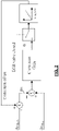
- Figure 1 shows the sensors in a known schematic of a part of an engine circuit, including the engine, an EGR cooler, a turbine , where the outlet of the EGR cooler is brought to the inlet of the cylinders, and the outlet of the cylinders is brought to the turbine and to the inlet of the EGR cooler through an EGR valve.
- the turbine mass flow is adapted such that it matches the total gas mass flow, when the EGR valve is closed and thus the EGR mass flow is zero.
- the basic idea of the invention is the determination of the EGR rate using pressure and temperature sensors. Instead of calculating the EGR rate directly from the pressure drop over the EGR line, the EGR mass flow dm EGR is obtained indirectly from the difference between the total exhaust gas mass flow dm Tot across the cylinders and the turbine mass flow dm Turb across the turbine.
- the total exhaust gas mass flow dm Tot is obtained from a model, where the total gas charge in a cylinder per stroke is calculated using p2, T2, and possibly also p3 and T3.
- Such models which are often referred to as “speeddensity models" are widely used and known.
- the actual gas mass flow can be calculated from the gas charge.
- the total exhaust gas mass flow dm Tot is then obtained as the sum of the total gas mass flow and the fuel mass flow.
- the turbine mass flow dm Turb is calculated using a model.
- the turbine mass flow dm Turb can be obtained from the upstream and the downstream pressures p3 and p4 of the turbine, respectively, and from the upstream temperature T3 of the turbine.
- the pressure p3 is obtained from a sensor, the pressure p4 from a model or from a sensor.
- T3 is usually obtained from a model.
- VGT variable geometry turbine
- the opening of the waste gate has also to be taken into account for the determination of the turbine mass flow dm Turb .
- the calculation of the turbine mass flow dm Turb can be made applying well known expressions, for example derived from a turbine model determined by using a known expression similar to a throttle equation, as described for example in: Guzzella, Onder: "Introduction to Modeling and Control of Internal Combustion Engine Systems", ISBN3-540-22274-x, Springer-Verlag, Berlin, 2004 .
- the EGR mass flow dm EGR can now be obtained as the difference between the total exhaust gas mass flow dm Tot and the turbine mass flow dm Turb .
- dm EGR dm Tot ⁇ dm Turb
- EGR mass flow dm EGR determination is improved using an adaptation algorithm.
- EGR valve When the EGR valve is closed, the EGR mass flow is approximately zero. Approximately zero means that there is always an irrelevant small value, because the valve never entirely closes.
- the turbine mass flow dm Turb equals the total mass flow dm Tot .
- Either the EGR valve is closed deliberately in order to allow an adaptation procedure, or conditions are utilised, where the valve is closed anyway, for example during acceleration. Since the turbine and the cylinder outlet are very close, the adaptation algorithm can even be applied during transient operation.
- Figure 2 shows a block diagram of a non limiting example of the adaptation algorithm. According to the invention, it should be any adaptation algorithm, where the total exhaust gas mass flow dm Tot is adjusted such that it is equal to the turbine mass flow dm Turb when the EGR valve is closed.
- the value of dm Turb is added with a feedback correction offset value coming from an integrator.
- the result R1 is subtracted from the value of dm Tot and is fed to the input of a block of gain correction, which can be a factor, which is multiplied with the difference between the total mass flow and the corrected turbine mass flow R1.
- the output of the gain correction is fed to the integrator only if the EGR valve is closed. If the EGR valve is not closed, the input of the integrator is zero.
- a correction factor can be multiplied with the turbine mass flow dm Turb or any other mathematical/algebraic calculation can be used such as correction curves or correction maps.
- the total mass flow dm Tot can be corrected in the same manner.
- a correction curve or map can be used to calculate the correction offset, factor, or function.
- the turbine mass flow dm Turb of the first or second turbine has to be determined, for mid pressure EGR, the turbine mass flow dm Turb of the second turbine.
- the method of the present invention can be advantageously implemented through a program for computer comprising program coding means for the implementation of one or more steps of the method, when this program is running on a computer. Therefore, it is understood that the scope of protection is extended to such a program for computer and in addition to a computer readable means having a recorded message therein, said computer readable means comprising program coding means for the implementation of one or more steps of the method, when this program is run on a computer.
Priority Applications (2)
| Application Number | Priority Date | Filing Date | Title |
|---|---|---|---|
| EP19203154.0A EP3633169B1 (en) | 2009-12-23 | 2009-12-23 | Method and apparatus for measuring and controlling the egr rate in a combustion engine |
| ES19203154T ES2931034T3 (ru) | 2009-12-23 | 2009-12-23 |
Applications Claiming Priority (2)
| Application Number | Priority Date | Filing Date | Title |
|---|---|---|---|
| EP19203154.0A EP3633169B1 (en) | 2009-12-23 | 2009-12-23 | Method and apparatus for measuring and controlling the egr rate in a combustion engine |
| EP09180649.7A EP2339153B1 (en) | 2009-12-23 | 2009-12-23 | Method and apparatus for measuring and controlling the egr rate in a combustion engine |
Related Parent Applications (1)
| Application Number | Title | Priority Date | Filing Date |
|---|---|---|---|
| EP09180649.7A Division EP2339153B1 (en) | 2009-12-23 | 2009-12-23 | Method and apparatus for measuring and controlling the egr rate in a combustion engine |
Publications (2)
| Publication Number | Publication Date |
|---|---|
| EP3633169A1 EP3633169A1 (en) | 2020-04-08 |
| EP3633169B1 true EP3633169B1 (en) | 2022-10-12 |
Family
ID=42229161
Family Applications (2)
| Application Number | Title | Priority Date | Filing Date |
|---|---|---|---|
| EP09180649.7A Active EP2339153B1 (en) | 2009-12-23 | 2009-12-23 | Method and apparatus for measuring and controlling the egr rate in a combustion engine |
| EP19203154.0A Active EP3633169B1 (en) | 2009-12-23 | 2009-12-23 | Method and apparatus for measuring and controlling the egr rate in a combustion engine |
Family Applications Before (1)
| Application Number | Title | Priority Date | Filing Date |
|---|---|---|---|
| EP09180649.7A Active EP2339153B1 (en) | 2009-12-23 | 2009-12-23 | Method and apparatus for measuring and controlling the egr rate in a combustion engine |
Country Status (9)
| Country | Link |
|---|---|
| US (1) | US9267452B2 (ru) |
| EP (2) | EP2339153B1 (ru) |
| JP (1) | JP5841539B2 (ru) |
| CN (1) | CN102667115B (ru) |
| AU (1) | AU2010334853B2 (ru) |
| BR (1) | BR112012015668B1 (ru) |
| ES (2) | ES2758794T3 (ru) |
| RU (1) | RU2557079C2 (ru) |
| WO (1) | WO2011076837A1 (ru) |
Families Citing this family (15)
| Publication number | Priority date | Publication date | Assignee | Title |
|---|---|---|---|---|
| DE102011017779B4 (de) * | 2011-04-29 | 2021-10-07 | Robert Bosch Gmbh | Verfahren zur Bestimmung des Niederdruck-Abgasrückführungsmassenstroms in dem Luftsystem einer Brennkraftmaschine |
| GB2493748A (en) | 2011-08-17 | 2013-02-20 | Gm Global Tech Operations Inc | Unit for estimating the rotational speed of a turbocharger |
| DE102012222899A1 (de) * | 2012-12-12 | 2014-06-12 | Robert Bosch Gmbh | Verfahren zur Ermittlung der Brennstoffqualität bei einer Brennkraftmaschine insbesondere eines Kraftfahrzeuges |
| TWI654368B (zh) * | 2013-06-28 | 2019-03-21 | 美商艾克頌美孚上游研究公司 | 用於控制在廢氣再循環氣渦輪機系統中的廢氣流之系統、方法與媒體 |
| JP6346498B2 (ja) * | 2014-06-12 | 2018-06-20 | 日野自動車株式会社 | Egrガス流量の推定装置及び推定方法 |
| US9845749B2 (en) * | 2015-02-06 | 2017-12-19 | Ford Global Technologies, Llc | System and methods for diagnosing soot accumulation on an exhaust gas recirculation valve |
| CN106481465B (zh) * | 2015-08-27 | 2019-09-03 | 长城汽车股份有限公司 | Egr率的计算方法、系统及车辆 |
| MY176701A (en) * | 2016-09-07 | 2020-08-19 | Nissan Motor | Engine control method and control device |
| EP3548729B1 (en) | 2016-11-29 | 2023-02-22 | Garrett Transportation I Inc. | An inferential flow sensor |
| JP6838611B2 (ja) * | 2017-02-01 | 2021-03-03 | 日産自動車株式会社 | 内燃機関の吸気制御方法及び吸気制御装置 |
| DE102017205829A1 (de) * | 2017-04-05 | 2018-10-11 | Robert Bosch Gmbh | Verfahren und Vorrichtung zum Bestimmen einer Gassystemgröße in einem Verbrennungsmotor |
| CN110869595B (zh) * | 2017-09-23 | 2022-09-02 | 沃尔沃卡车集团 | 发动机系统及其中的排气再循环流量测量和排放控制方法 |
| US20190368435A1 (en) * | 2018-05-31 | 2019-12-05 | GM Global Technology Operations LLC | High pressure egr flow model hybrid strategy |
| CN109635484A (zh) * | 2018-12-24 | 2019-04-16 | 河北工程大学 | 基于多学科优化的混合动力车辆动力系统优化测试方法 |
| EP4219921A1 (en) | 2022-01-31 | 2023-08-02 | Winterthur Gas & Diesel Ltd. | Internal combustion engine and method for operating an internal combustion engine |
Family Cites Families (22)
| Publication number | Priority date | Publication date | Assignee | Title |
|---|---|---|---|---|
| DE4214648A1 (de) * | 1992-05-02 | 1993-11-04 | Bosch Gmbh Robert | System zur steuerung einer brennkraftmaschine |
| US5753805A (en) * | 1996-12-02 | 1998-05-19 | General Motors Corporation | Method for determining pneumatic states in an internal combustion engine system |
| KR20010023961A (ko) * | 1997-09-17 | 2001-03-26 | 클라우스 포스 | 내연기관에서 가스 흡기를 결정하기 위한 방법 및 장치 |
| JP3577961B2 (ja) * | 1998-02-27 | 2004-10-20 | トヨタ自動車株式会社 | 燃焼式ヒータを有する内燃機関 |
| DE19963358A1 (de) * | 1999-12-28 | 2001-07-12 | Bosch Gmbh Robert | Verfahren und Vorrichtung zur Steuerung einer Brennkraftmaschine mit einem Luftsystem |
| DE60131472T2 (de) * | 2000-03-31 | 2008-02-28 | Detroit Diesel Corp., Detroit | Verfahren zur Steuerung einer Brennkraftmaschine |
| US6422219B1 (en) * | 2000-11-28 | 2002-07-23 | Detroit Diesel Corporation | Electronic controlled engine exhaust treatment system to reduce NOx emissions |
| US6785604B2 (en) * | 2002-05-15 | 2004-08-31 | Caterpillar Inc | Diagnostic systems for turbocharged engines |
| CN1820133A (zh) * | 2003-08-08 | 2006-08-16 | 霍尼韦尔国际公司 | 压缩机的喘振控制系统 |
| DE102004024272A1 (de) * | 2004-05-15 | 2005-12-01 | Lanxess Deutschland Gmbh | Pfropfpolymerisathaltige Massen für die Extrusionsverarbeitung |
| DE102004024270A1 (de) * | 2004-05-15 | 2005-12-01 | Daimlerchrysler Ag | Verfahren und Vorrichtung zur Bestimmung einer Abgasrückführungsrate |
| JP4583943B2 (ja) * | 2005-01-18 | 2010-11-17 | 本田技研工業株式会社 | 内燃機関の過給圧制御装置 |
| JP4247191B2 (ja) | 2005-03-08 | 2009-04-02 | 三菱重工業株式会社 | ガスエンジンのガス供給装置及び運転方法 |
| JP4449816B2 (ja) * | 2005-05-13 | 2010-04-14 | 株式会社日立製作所 | Egrガス流量の検出装置およびエンジンの制御方法 |
| FR2886345B1 (fr) * | 2005-05-30 | 2010-08-27 | Inst Francais Du Petrole | Methode d'estimation par un filtre non-lineaire adaptatif de la richesse dans un cylindre d'un moteur a combustion |
| JP4692202B2 (ja) * | 2005-10-06 | 2011-06-01 | いすゞ自動車株式会社 | 2段過給式エンジンのegrシステム |
| JP4681465B2 (ja) * | 2006-02-08 | 2011-05-11 | 三菱重工業株式会社 | 排気ターボ過給機 |
| JP4301295B2 (ja) * | 2007-01-18 | 2009-07-22 | トヨタ自動車株式会社 | 内燃機関のegrシステム |
| US7788922B2 (en) * | 2007-10-04 | 2010-09-07 | Delphi Technologies, Inc. | System and method for model based boost control of turbo-charged engines |
| US7512479B1 (en) * | 2007-11-19 | 2009-03-31 | Southwest Research Institute | Air fraction estimation for internal combustion engines with dual-loop EGR systems |
| JP4853471B2 (ja) * | 2007-12-19 | 2012-01-11 | 株式会社デンソー | 過給機付き内燃機関の制御装置 |
| GB0800451D0 (en) * | 2008-01-11 | 2008-02-20 | Cummins Turbo Tech Ltd | A turbomachine system and turbine therefor |
-
2009
- 2009-12-23 EP EP09180649.7A patent/EP2339153B1/en active Active
- 2009-12-23 EP EP19203154.0A patent/EP3633169B1/en active Active
- 2009-12-23 ES ES09180649T patent/ES2758794T3/es active Active
- 2009-12-23 ES ES19203154T patent/ES2931034T3/es active Active
-
2010
- 2010-12-22 CN CN201080058584.8A patent/CN102667115B/zh active Active
- 2010-12-22 BR BR112012015668A patent/BR112012015668B1/pt active IP Right Grant
- 2010-12-22 US US13/261,333 patent/US9267452B2/en active Active
- 2010-12-22 AU AU2010334853A patent/AU2010334853B2/en active Active
- 2010-12-22 JP JP2012545319A patent/JP5841539B2/ja active Active
- 2010-12-22 RU RU2012131310/07A patent/RU2557079C2/ru active
- 2010-12-22 WO PCT/EP2010/070470 patent/WO2011076837A1/en active Application Filing
Also Published As
| Publication number | Publication date |
|---|---|
| BR112012015668A2 (pt) | 2016-05-24 |
| EP2339153A1 (en) | 2011-06-29 |
| AU2010334853B2 (en) | 2014-05-29 |
| CN102667115B (zh) | 2016-02-17 |
| ES2758794T3 (es) | 2020-05-06 |
| JP5841539B2 (ja) | 2016-01-13 |
| BR112012015668B1 (pt) | 2019-12-10 |
| US20120325188A1 (en) | 2012-12-27 |
| EP2339153B1 (en) | 2019-10-16 |
| ES2931034T3 (ru) | 2022-12-23 |
| RU2557079C2 (ru) | 2015-07-20 |
| EP3633169A1 (en) | 2020-04-08 |
| RU2012131310A (ru) | 2014-01-27 |
| JP2013515895A (ja) | 2013-05-09 |
| US9267452B2 (en) | 2016-02-23 |
| CN102667115A (zh) | 2012-09-12 |
| WO2011076837A1 (en) | 2011-06-30 |
| AU2010334853A1 (en) | 2012-08-09 |
Similar Documents
| Publication | Publication Date | Title |
|---|---|---|
| EP3633169B1 (en) | Method and apparatus for measuring and controlling the egr rate in a combustion engine | |
| EP1607606B1 (en) | Method and device for determining an internal combustion engine intake air flow rate based on the measurement of the oxygen concentration in the gaseous mixture taken in by the engine | |
| RU2557668C2 (ru) | Способ и устройство для оценки выбросов оксидов азота в двигателях внутреннего сгорания | |
| EP2198141B1 (en) | Exhaust-gas recirculation apparatus and exhaust-gas recirculation flow rate estimation method for internal combustion engines | |
| US7946162B2 (en) | Method for estimating the oxygen concentration in internal combustion engines | |
| US6877369B2 (en) | EGR-gas flow rate estimation apparatus for internal combustion engine | |
| EP2284376B1 (en) | Exhaust gas recirculation apparatus for an internal combustion engine | |
| KR101974654B1 (ko) | 내연기관을 구비한 엔진 시스템에서 물리적 변수를 위한 모델링 값을 결정하는 방법 및 그 장치 | |
| US6981492B2 (en) | Method for determining an exhaust gas recirculation amount | |
| JP2013011270A (ja) | 内燃機関の筒内流入egrガス流量推定装置 | |
| KR20130091681A (ko) | 내연기관의 공기 공급 채널 내 산소 센서의 신호 적응 방법 및 장치 | |
| JP2018119403A (ja) | 内燃機関の制御装置 | |
| EP3128159B1 (en) | Method to control a low-pressure exhaust gas recirculation egr circuit in an internal combustion engine | |
| US20090018784A1 (en) | Method of estimation of the pressure drop between two sections of the exhaust line of an internal combustion engine | |
| CN116447028A (zh) | 发动机系统egr率的控制方法、装置、电子设备和存储介质 | |
| KR20170007460A (ko) | 내연 엔진을 동작시키기 위한 방법 및 디바이스 | |
| CN104179601A (zh) | 用于确定在内燃机的高压-废气再循环系统中的质量流量的方法和控制单元 | |
| EP3752727B1 (en) | Engine air flow estimation | |
| CN110869595A (zh) | 用于测量发动机系统中的排气再循环流量的方法、控制发动机系统中的排放的方法、以及发动机系统 | |
| JP2020063740A (ja) | 内燃エンジンのシリンダー内に存在する再循環排気ガスの濃度を特定するための推定方法 | |
| JP2004143964A (ja) | 内燃機関のegr流量算出装置および内燃機関の制御装置 | |
| KR102187578B1 (ko) | 실린더 공기량 연산 방법 | |
| CN116202775A (zh) | 一种发动机缸内气量预估方法及系统 | |
| EP1559891A1 (en) | Turbocharged engine control method having improved smoke control | |
| JP2007009867A (ja) | 過給機付き内燃機関の吸入空気量算出装置 |
Legal Events
| Date | Code | Title | Description |
|---|---|---|---|
| PUAI | Public reference made under article 153(3) epc to a published international application that has entered the european phase |
Free format text: ORIGINAL CODE: 0009012 |
|
| STAA | Information on the status of an ep patent application or granted ep patent |
Free format text: STATUS: THE APPLICATION HAS BEEN PUBLISHED |
|
| AC | Divisional application: reference to earlier application |
Ref document number: 2339153 Country of ref document: EP Kind code of ref document: P |
|
| AK | Designated contracting states |
Kind code of ref document: A1 Designated state(s): AT BE BG CH CY CZ DE DK EE ES FI FR GB GR HR HU IE IS IT LI LT LU LV MC MK MT NL NO PL PT RO SE SI SK SM TR |
|
| STAA | Information on the status of an ep patent application or granted ep patent |
Free format text: STATUS: REQUEST FOR EXAMINATION WAS MADE |
|
| 17P | Request for examination filed |
Effective date: 20200930 |
|
| RBV | Designated contracting states (corrected) |
Designated state(s): AT BE BG CH CY CZ DE DK EE ES FI FR GB GR HR HU IE IS IT LI LT LU LV MC MK MT NL NO PL PT RO SE SI SK SM TR |
|
| GRAP | Despatch of communication of intention to grant a patent |
Free format text: ORIGINAL CODE: EPIDOSNIGR1 |
|
| STAA | Information on the status of an ep patent application or granted ep patent |
Free format text: STATUS: GRANT OF PATENT IS INTENDED |
|
| RIC1 | Information provided on ipc code assigned before grant |
Ipc: F02D 41/24 20060101ALI20220405BHEP Ipc: F02D 41/00 20060101AFI20220405BHEP |
|
| INTG | Intention to grant announced |
Effective date: 20220509 |
|
| GRAS | Grant fee paid |
Free format text: ORIGINAL CODE: EPIDOSNIGR3 |
|
| GRAA | (expected) grant |
Free format text: ORIGINAL CODE: 0009210 |
|
| STAA | Information on the status of an ep patent application or granted ep patent |
Free format text: STATUS: THE PATENT HAS BEEN GRANTED |
|
| AC | Divisional application: reference to earlier application |
Ref document number: 2339153 Country of ref document: EP Kind code of ref document: P |
|
| AK | Designated contracting states |
Kind code of ref document: B1 Designated state(s): AT BE BG CH CY CZ DE DK EE ES FI FR GB GR HR HU IE IS IT LI LT LU LV MC MK MT NL NO PL PT RO SE SI SK SM TR |
|
| REG | Reference to a national code |
Ref country code: GB Ref legal event code: FG4D |
|
| REG | Reference to a national code |
Ref country code: CH Ref legal event code: EP |
|
| REG | Reference to a national code |
Ref country code: DE Ref legal event code: R096 Ref document number: 602009064640 Country of ref document: DE |
|
| REG | Reference to a national code |
Ref country code: IE Ref legal event code: FG4D |
|
| REG | Reference to a national code |
Ref country code: AT Ref legal event code: REF Ref document number: 1524311 Country of ref document: AT Kind code of ref document: T Effective date: 20221115 |
|
| REG | Reference to a national code |
Ref country code: ES Ref legal event code: FG2A Ref document number: 2931034 Country of ref document: ES Kind code of ref document: T3 Effective date: 20221223 |
|
| PGFP | Annual fee paid to national office [announced via postgrant information from national office to epo] |
Ref country code: DE Payment date: 20221028 Year of fee payment: 14 |
|
| REG | Reference to a national code |
Ref country code: LT Ref legal event code: MG9D |
|
| REG | Reference to a national code |
Ref country code: NL Ref legal event code: MP Effective date: 20221012 |
|
| REG | Reference to a national code |
Ref country code: AT Ref legal event code: MK05 Ref document number: 1524311 Country of ref document: AT Kind code of ref document: T Effective date: 20221012 |
|
| PG25 | Lapsed in a contracting state [announced via postgrant information from national office to epo] |
Ref country code: NL Free format text: LAPSE BECAUSE OF FAILURE TO SUBMIT A TRANSLATION OF THE DESCRIPTION OR TO PAY THE FEE WITHIN THE PRESCRIBED TIME-LIMIT Effective date: 20221012 |
|
| PG25 | Lapsed in a contracting state [announced via postgrant information from national office to epo] |
Ref country code: SE Free format text: LAPSE BECAUSE OF FAILURE TO SUBMIT A TRANSLATION OF THE DESCRIPTION OR TO PAY THE FEE WITHIN THE PRESCRIBED TIME-LIMIT Effective date: 20221012 Ref country code: PT Free format text: LAPSE BECAUSE OF FAILURE TO SUBMIT A TRANSLATION OF THE DESCRIPTION OR TO PAY THE FEE WITHIN THE PRESCRIBED TIME-LIMIT Effective date: 20230213 Ref country code: NO Free format text: LAPSE BECAUSE OF FAILURE TO SUBMIT A TRANSLATION OF THE DESCRIPTION OR TO PAY THE FEE WITHIN THE PRESCRIBED TIME-LIMIT Effective date: 20230112 Ref country code: LT Free format text: LAPSE BECAUSE OF FAILURE TO SUBMIT A TRANSLATION OF THE DESCRIPTION OR TO PAY THE FEE WITHIN THE PRESCRIBED TIME-LIMIT Effective date: 20221012 Ref country code: FI Free format text: LAPSE BECAUSE OF FAILURE TO SUBMIT A TRANSLATION OF THE DESCRIPTION OR TO PAY THE FEE WITHIN THE PRESCRIBED TIME-LIMIT Effective date: 20221012 Ref country code: AT Free format text: LAPSE BECAUSE OF FAILURE TO SUBMIT A TRANSLATION OF THE DESCRIPTION OR TO PAY THE FEE WITHIN THE PRESCRIBED TIME-LIMIT Effective date: 20221012 |
|
| PGFP | Annual fee paid to national office [announced via postgrant information from national office to epo] |
Ref country code: ES Payment date: 20230120 Year of fee payment: 14 |
|
| PG25 | Lapsed in a contracting state [announced via postgrant information from national office to epo] |
Ref country code: PL Free format text: LAPSE BECAUSE OF FAILURE TO SUBMIT A TRANSLATION OF THE DESCRIPTION OR TO PAY THE FEE WITHIN THE PRESCRIBED TIME-LIMIT Effective date: 20221012 Ref country code: LV Free format text: LAPSE BECAUSE OF FAILURE TO SUBMIT A TRANSLATION OF THE DESCRIPTION OR TO PAY THE FEE WITHIN THE PRESCRIBED TIME-LIMIT Effective date: 20221012 Ref country code: IS Free format text: LAPSE BECAUSE OF FAILURE TO SUBMIT A TRANSLATION OF THE DESCRIPTION OR TO PAY THE FEE WITHIN THE PRESCRIBED TIME-LIMIT Effective date: 20230212 Ref country code: HR Free format text: LAPSE BECAUSE OF FAILURE TO SUBMIT A TRANSLATION OF THE DESCRIPTION OR TO PAY THE FEE WITHIN THE PRESCRIBED TIME-LIMIT Effective date: 20221012 Ref country code: GR Free format text: LAPSE BECAUSE OF FAILURE TO SUBMIT A TRANSLATION OF THE DESCRIPTION OR TO PAY THE FEE WITHIN THE PRESCRIBED TIME-LIMIT Effective date: 20230113 |
|
| P01 | Opt-out of the competence of the unified patent court (upc) registered |
Effective date: 20230519 |
|
| REG | Reference to a national code |
Ref country code: DE Ref legal event code: R097 Ref document number: 602009064640 Country of ref document: DE |
|
| PG25 | Lapsed in a contracting state [announced via postgrant information from national office to epo] |
Ref country code: SM Free format text: LAPSE BECAUSE OF FAILURE TO SUBMIT A TRANSLATION OF THE DESCRIPTION OR TO PAY THE FEE WITHIN THE PRESCRIBED TIME-LIMIT Effective date: 20221012 Ref country code: RO Free format text: LAPSE BECAUSE OF FAILURE TO SUBMIT A TRANSLATION OF THE DESCRIPTION OR TO PAY THE FEE WITHIN THE PRESCRIBED TIME-LIMIT Effective date: 20221012 Ref country code: EE Free format text: LAPSE BECAUSE OF FAILURE TO SUBMIT A TRANSLATION OF THE DESCRIPTION OR TO PAY THE FEE WITHIN THE PRESCRIBED TIME-LIMIT Effective date: 20221012 Ref country code: DK Free format text: LAPSE BECAUSE OF FAILURE TO SUBMIT A TRANSLATION OF THE DESCRIPTION OR TO PAY THE FEE WITHIN THE PRESCRIBED TIME-LIMIT Effective date: 20221012 Ref country code: CZ Free format text: LAPSE BECAUSE OF FAILURE TO SUBMIT A TRANSLATION OF THE DESCRIPTION OR TO PAY THE FEE WITHIN THE PRESCRIBED TIME-LIMIT Effective date: 20221012 |
|
| REG | Reference to a national code |
Ref country code: CH Ref legal event code: PL |
|
| PLBE | No opposition filed within time limit |
Free format text: ORIGINAL CODE: 0009261 |
|
| STAA | Information on the status of an ep patent application or granted ep patent |
Free format text: STATUS: NO OPPOSITION FILED WITHIN TIME LIMIT |
|
| REG | Reference to a national code |
Ref country code: BE Ref legal event code: MM Effective date: 20221231 |
|
| PG25 | Lapsed in a contracting state [announced via postgrant information from national office to epo] |
Ref country code: SK Free format text: LAPSE BECAUSE OF FAILURE TO SUBMIT A TRANSLATION OF THE DESCRIPTION OR TO PAY THE FEE WITHIN THE PRESCRIBED TIME-LIMIT Effective date: 20221012 Ref country code: LU Free format text: LAPSE BECAUSE OF NON-PAYMENT OF DUE FEES Effective date: 20221223 |
|
| 26N | No opposition filed |
Effective date: 20230713 |
|
| GBPC | Gb: european patent ceased through non-payment of renewal fee |
Effective date: 20230112 |
|
| PG25 | Lapsed in a contracting state [announced via postgrant information from national office to epo] |
Ref country code: LI Free format text: LAPSE BECAUSE OF NON-PAYMENT OF DUE FEES Effective date: 20221231 Ref country code: IE Free format text: LAPSE BECAUSE OF NON-PAYMENT OF DUE FEES Effective date: 20221223 Ref country code: GB Free format text: LAPSE BECAUSE OF NON-PAYMENT OF DUE FEES Effective date: 20230112 Ref country code: CH Free format text: LAPSE BECAUSE OF NON-PAYMENT OF DUE FEES Effective date: 20221231 |
|
| PG25 | Lapsed in a contracting state [announced via postgrant information from national office to epo] |
Ref country code: SI Free format text: LAPSE BECAUSE OF FAILURE TO SUBMIT A TRANSLATION OF THE DESCRIPTION OR TO PAY THE FEE WITHIN THE PRESCRIBED TIME-LIMIT Effective date: 20221012 Ref country code: BE Free format text: LAPSE BECAUSE OF NON-PAYMENT OF DUE FEES Effective date: 20221231 |
|
| PGFP | Annual fee paid to national office [announced via postgrant information from national office to epo] |
Ref country code: IT Payment date: 20231201 Year of fee payment: 15 Ref country code: FR Payment date: 20231226 Year of fee payment: 15 |
|
| PG25 | Lapsed in a contracting state [announced via postgrant information from national office to epo] |
Ref country code: HU Free format text: LAPSE BECAUSE OF FAILURE TO SUBMIT A TRANSLATION OF THE DESCRIPTION OR TO PAY THE FEE WITHIN THE PRESCRIBED TIME-LIMIT; INVALID AB INITIO Effective date: 20091223 |
|
| PGFP | Annual fee paid to national office [announced via postgrant information from national office to epo] |
Ref country code: ES Payment date: 20240119 Year of fee payment: 15 |