EP3633132A1 - Verfahren zur herstellung eines dichtungsprofils für fenster, türen oder fassaden und zum montieren der dichtung an der tür - Google Patents
Verfahren zur herstellung eines dichtungsprofils für fenster, türen oder fassaden und zum montieren der dichtung an der tür Download PDFInfo
- Publication number
- EP3633132A1 EP3633132A1 EP19200390.3A EP19200390A EP3633132A1 EP 3633132 A1 EP3633132 A1 EP 3633132A1 EP 19200390 A EP19200390 A EP 19200390A EP 3633132 A1 EP3633132 A1 EP 3633132A1
- Authority
- EP
- European Patent Office
- Prior art keywords
- seal
- door
- window
- sealing surface
- frame
- Prior art date
- Legal status (The legal status is an assumption and is not a legal conclusion. Google has not performed a legal analysis and makes no representation as to the accuracy of the status listed.)
- Granted
Links
Images

Classifications
-
- E—FIXED CONSTRUCTIONS
- E06—DOORS, WINDOWS, SHUTTERS, OR ROLLER BLINDS IN GENERAL; LADDERS
- E06B—FIXED OR MOVABLE CLOSURES FOR OPENINGS IN BUILDINGS, VEHICLES, FENCES OR LIKE ENCLOSURES IN GENERAL, e.g. DOORS, WINDOWS, BLINDS, GATES
- E06B7/00—Special arrangements or measures in connection with doors or windows
- E06B7/16—Sealing arrangements on wings or parts co-operating with the wings
- E06B7/22—Sealing arrangements on wings or parts co-operating with the wings by means of elastic edgings, e.g. elastic rubber tubes; by means of resilient edgings, e.g. felt or plush strips, resilient metal strips
- E06B7/23—Plastic, sponge rubber, or like strips or tubes
- E06B7/2305—Plastic, sponge rubber, or like strips or tubes with an integrally formed part for fixing the edging
- E06B7/2307—Plastic, sponge rubber, or like strips or tubes with an integrally formed part for fixing the edging with a single sealing-line or -plane between the wing and the part co-operating with the wing
- E06B7/2309—Plastic, sponge rubber, or like strips or tubes with an integrally formed part for fixing the edging with a single sealing-line or -plane between the wing and the part co-operating with the wing with a hollow sealing part
-
- E—FIXED CONSTRUCTIONS
- E06—DOORS, WINDOWS, SHUTTERS, OR ROLLER BLINDS IN GENERAL; LADDERS
- E06B—FIXED OR MOVABLE CLOSURES FOR OPENINGS IN BUILDINGS, VEHICLES, FENCES OR LIKE ENCLOSURES IN GENERAL, e.g. DOORS, WINDOWS, BLINDS, GATES
- E06B3/00—Window sashes, door leaves, or like elements for closing wall or like openings; Layout of fixed or moving closures, e.g. windows in wall or like openings; Features of rigidly-mounted outer frames relating to the mounting of wing frames
- E06B3/54—Fixing of glass panes or like plates
- E06B3/58—Fixing of glass panes or like plates by means of borders, cleats, or the like
- E06B3/62—Fixing of glass panes or like plates by means of borders, cleats, or the like of rubber-like elastic cleats
-
- E—FIXED CONSTRUCTIONS
- E06—DOORS, WINDOWS, SHUTTERS, OR ROLLER BLINDS IN GENERAL; LADDERS
- E06B—FIXED OR MOVABLE CLOSURES FOR OPENINGS IN BUILDINGS, VEHICLES, FENCES OR LIKE ENCLOSURES IN GENERAL, e.g. DOORS, WINDOWS, BLINDS, GATES
- E06B7/00—Special arrangements or measures in connection with doors or windows
- E06B7/16—Sealing arrangements on wings or parts co-operating with the wings
- E06B7/22—Sealing arrangements on wings or parts co-operating with the wings by means of elastic edgings, e.g. elastic rubber tubes; by means of resilient edgings, e.g. felt or plush strips, resilient metal strips
- E06B7/23—Plastic, sponge rubber, or like strips or tubes
- E06B7/2314—Plastic, sponge rubber, or like strips or tubes characterised by the material
-
- E—FIXED CONSTRUCTIONS
- E06—DOORS, WINDOWS, SHUTTERS, OR ROLLER BLINDS IN GENERAL; LADDERS
- E06B—FIXED OR MOVABLE CLOSURES FOR OPENINGS IN BUILDINGS, VEHICLES, FENCES OR LIKE ENCLOSURES IN GENERAL, e.g. DOORS, WINDOWS, BLINDS, GATES
- E06B3/00—Window sashes, door leaves, or like elements for closing wall or like openings; Layout of fixed or moving closures, e.g. windows in wall or like openings; Features of rigidly-mounted outer frames relating to the mounting of wing frames
- E06B3/54—Fixing of glass panes or like plates
- E06B3/58—Fixing of glass panes or like plates by means of borders, cleats, or the like
- E06B3/62—Fixing of glass panes or like plates by means of borders, cleats, or the like of rubber-like elastic cleats
- E06B2003/6217—Fixing of glass panes or like plates by means of borders, cleats, or the like of rubber-like elastic cleats with specific fixing means
- E06B2003/6223—Fixing of glass panes or like plates by means of borders, cleats, or the like of rubber-like elastic cleats with specific fixing means with protruding parts anchored in grooves
-
- E—FIXED CONSTRUCTIONS
- E06—DOORS, WINDOWS, SHUTTERS, OR ROLLER BLINDS IN GENERAL; LADDERS
- E06B—FIXED OR MOVABLE CLOSURES FOR OPENINGS IN BUILDINGS, VEHICLES, FENCES OR LIKE ENCLOSURES IN GENERAL, e.g. DOORS, WINDOWS, BLINDS, GATES
- E06B3/00—Window sashes, door leaves, or like elements for closing wall or like openings; Layout of fixed or moving closures, e.g. windows in wall or like openings; Features of rigidly-mounted outer frames relating to the mounting of wing frames
- E06B3/54—Fixing of glass panes or like plates
- E06B3/58—Fixing of glass panes or like plates by means of borders, cleats, or the like
- E06B3/62—Fixing of glass panes or like plates by means of borders, cleats, or the like of rubber-like elastic cleats
- E06B2003/625—Specific form characteristics
- E06B2003/6264—Specific form characteristics hollow
-
- E—FIXED CONSTRUCTIONS
- E06—DOORS, WINDOWS, SHUTTERS, OR ROLLER BLINDS IN GENERAL; LADDERS
- E06B—FIXED OR MOVABLE CLOSURES FOR OPENINGS IN BUILDINGS, VEHICLES, FENCES OR LIKE ENCLOSURES IN GENERAL, e.g. DOORS, WINDOWS, BLINDS, GATES
- E06B3/00—Window sashes, door leaves, or like elements for closing wall or like openings; Layout of fixed or moving closures, e.g. windows in wall or like openings; Features of rigidly-mounted outer frames relating to the mounting of wing frames
- E06B3/54—Fixing of glass panes or like plates
- E06B3/58—Fixing of glass panes or like plates by means of borders, cleats, or the like
- E06B3/62—Fixing of glass panes or like plates by means of borders, cleats, or the like of rubber-like elastic cleats
- E06B2003/627—Fixing of glass panes or like plates by means of borders, cleats, or the like of rubber-like elastic cleats with specific characteristics concerning the material
- E06B2003/6276—Fixing of glass panes or like plates by means of borders, cleats, or the like of rubber-like elastic cleats with specific characteristics concerning the material with parts of differing nature, e.g. hardness
Definitions
- the invention relates to a method for producing a seal for a window or a door and for mounting the seal on the window or the door.
- a preferred sealing profile for sealing a gap between two elements of the window, the door or the facade that are movable relative to one another has a foot region and a sealing body.
- this sealing body can be designed as a hose area which has a chamber.
- Such a seal is mounted with its foot on a frame or on a casement. It also has a sealing area on its sealing body, against which, in a closed state of the window or the door, a corresponding element of the corresponding sash or blind frame, which is movable relative to the seal, bears.
- the state of the art DE 295 12 778 and the DE 298 14 787 called.
- the seal When the relatively movable element frame or casement, on which the stop seal is not mounted, is placed, the seal is loaded and deformed as a result. So that a good sealing effect is nevertheless achieved in the sealing area, it is necessary that at least the sealing area has a relatively smooth surface with a low roughness. It should also be avoided that leaks occur when the seal is installed in corner areas of frames of the windows or doors.
- a method for producing a seal - in the sense of a sealing profile - for a window or a door with a frame and a casement and for mounting the seal on the window or door - in other words, a manufacturing process with the following steps: Step A: thermoplastic extrusion of a seal with a foot area and a sealing body, in particular configured as a hose area, which has at least one sealing surface, from at least one provided thermoplastic elastomer TPE, with at least one film at least in the area of the sealing surface directly during extrusion of the seal on the at least one thermoplastic elastomer or optionally several foils are / are applied to the gasket which forms; Step B: Removing - especially peeling - the film from the sealing surface; and Step C: Providing the window or door and mounting the gasket to the frame or casement of the window or door.
- the invention also provides a window or door with a window frame and at least one casement frame and at least one seal serving as a stop seal on the window frame or casement frame, with a sealing surface on which a film was formed during extrusion, which was formed before assembly on the window frame. or sash frame has been removed from the sealing surface.
- a sealing profile is created which can be used in particular as a stop seal in the rebate area between the frame and the sash is usable. However, it can also be designed as a center seal, plug-in seal or system seal and can therefore be designed for multiple functions. It is dimensioned depending on the gap to be sealed and provided with a suitable foot area (snap-in foot or groove). According to the invention, it will also be avoided that leaks occur when the seal is installed in corner areas of frames of the windows or doors, because the seal nestles well in these areas when installed around the corners and there are wrinkles, such as those on films with films coated seals occur if the foils have not been removed before laying.
- the invention also provides a seal for a window or a door according to claim 6, which seal has a foot region and a sealing body, in particular designed as a hose region, and which is formed from thermoplastic elastomer by thermoplastic extrusion, with a sealing surface, on which a film was formed during extrusion, which was removed from the sealing surface again before assembly on the frame or sash and / or with at least one area made of non-foamed material, in particular a corner area for resting on a Window or door profile. It is also proposed to use this seal for installation in a window or door according to claim 6.
- Thermoplastic elastomers are materials that can be processed thermoplastically and have rubber-like properties.
- the TPE thermoplastic elastomers that can be used include TPE blends and block copolymers. Blends are alloys made of a plastic matrix and a soft material, e.g. B. an elastomer. Block copolymers are molecular chains with different segments, which assemble into "hard” and "soft” areas when they cool down.
- TPS styrene block copolymer
- TPU thermoplastic polyurethane
- TPC also known as TEEE (thermoplastic polyester elastomer)
- TPA thermoplastic polyether polyamide
- the individual types of TPE have different properties. differ in their properties. So TPC excels. B. from good mechanical strength, the TPU from good abrasion values.
- 3a and 3b show a seal 20 which can be designed in various ways and can therefore be referred to as a multi-function seal.
- This seal is preferably designed as a stop seal.
- seal 20 is thus designed as a sealing profile from which the desired seals are cut to length.
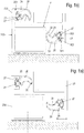
- One of the seals is in a fold area F between a frame 200 and a sash 300 in the groove 201 of a web 202 of the frame 200 used.
- Another of the seals 20 is inserted in the rebate area F between the frame 200 and the sash 300, however, in the groove 301 of a web 302 of the sash 300 of the wing.
- the seal 20 has a foot region 21.
- This foot region 21 is designed here as an undercut plug-in foot, which is designed for insertion into an undercut groove in the manner of the grooves 201, 301 of the Fig. 1 can be designed.
- the foot region 21 could alternatively also be designed in a different way.
- the seal 20 (see also 3a and 3b ) each has a sealing body adjoining the foot region 21.
- This sealing body is designed here as a hose area 22.
- the hose area 22 has a sealing surface 23.
- the sealing surface 23 is at least that surface or surface area of the hose region (22) on which, in the assembled state of the foot region 21, on a first element (frame 200 or sash frame 300) - see Fig. 1a a relatively movable second element in the closed state of the window or door - Fig. 1b - or comes into contact in a defined relative position of the two elements movable relative to one another (casement 300 or frame 200) or can come.
- the hose area 22 can preferably have incisions or cutouts in the manner of beads 24, but which do not penetrate the walls of the hose area 22. In this way, the tube area 22 can be deformed more easily when the wing 300 is closed and opened.
- the hose area 22 can be designed crescent-shaped, as shown here, so that it is under a load (force F in Fig. 2 ) as when closing a wing 300 Window occurs, evades to the side and deformed.
- force F in Fig. 2 a load
- the hose region 22 is bent or deformed here perpendicularly to the insertion direction by the acting force F and thus shorter parallel to the force F and wider by a distance L perpendicular to the force F.
- the sealing body or the hose region 22 and / or the foot region 21 are extruded completely or in sections from at least one thermoplastic elastomer M.
- thermoplastic elastomer M may be present in the extruded seal 20 in a foamed state or in a non-foamed state.
- the majority of the seal 20 can thus consist of the foamed thermoplastic elastomer.
- At least the sealing surface 23 preferably consists of the foamed thermoplastic elastomer.
- a part of the hose and / or the foot area 22 can also consist of the non-foamed plastic material (preferably again TPE).
- the non-foamed plastic material preferably again TPE
- it can be provided to form at least one corner region 25 of the hose region 22 from the non-foamed plastic material. This is because this stabilizes the structure of the seal 20, which is otherwise made of foamed material.
- the corner region 25 is supported on the frame 200 or the sash 300.
- the corner area 25 made of non-foamed material supports that the seal - see Fig. 2 - When the force F acts on the side rolls away or deforms itself, which is opposite the corner area.
- the corner area to the left is provided ( Fig. 2 below), so that the hose area 22 when the force F in Fig. 2 bends to the right or bends in ( Fig. 2 above). This effect is supported by the beads 24 also oriented on the tube area 22 in the direction facing away from the corner area.
- the sealing surface 23 should be as smooth and as little as possible.
- the seal 21 when extruding the seal 21, it is advantageous to have at least one film 26 run directly in the area of the sealing surface 23 when forming or extruding the seal 20, or to apply it to the seal 20 that is being formed.
- This film is preferably made of polypropylene.
- This film 25 is applied at least to the sealing surface 23.
- One or more further foils 27 can optionally also be applied to the seal 20 ( Fig. 4 , right part). These also preferably consist of polypropylene.
- the further foils 26 are preferably applied to the seal in a different area, for example to the foot area 21. In the foot area 21, the film 27 has a stabilizing effect when inserted into the corresponding groove. It improves the fit of the seal 20 in the groove.
- the film 26 is then removed again in the area of the sealing surface 23 ( Fig. 4 , middle part) and the seal 20 after removal is wound on a roll ( Fig. 4 , right part).
- Step A) of the manufacturing and assembly method comprises extruding a seal 20, wherein when the seal is extruded from at least one thermoplastic elastomer, at least one film 6 in the area of the sealing surface 23 or optionally a plurality of films 2627 is / are applied to the seal 20 that forms .
- At least the film 26 on the sealing surface 23 is preferably made of polypropylene.
- the film 26 has a significantly smoother surface than it would otherwise have a corresponding contact surface during extrusion could have. The effect of this is that the surface of the seal in these areas, that is to say at least in the area of the sealing surface 23, also has a very low roughness, so that very good tightness is permanently achieved in the area of the sealing surface 23, which essentially also after multiple opening and Closing is retained.
Landscapes
- Engineering & Computer Science (AREA)
- Civil Engineering (AREA)
- Structural Engineering (AREA)
- Specific Sealing Or Ventilating Devices For Doors And Windows (AREA)
- Extrusion Moulding Of Plastics Or The Like (AREA)
Abstract
Schritt A: thermoplastisches Extrudieren einer Dichtung (20) mit einem Fußbereich (21) und einem Dichtungskörper, insbesondere als Schlauchbereich (22) ausgestaltet, der wenigstens eine Dichtfläche (23) aufweist, aus wenigstens einem bereitgestellten thermoplastischen Elastomer (TPE), wobei direkt beim Extrudieren der Dichtung an dem wenigstens einen thermoplastischen Elastomer wenigstens eine Folie (26) zumindest im Bereich der Dichtfläche (23) oder optional mehrere Folien (26, 27) auf der sich bildenden Dichtung (20) aufgebracht wird/werden;
Schritt B: Entfernen - insbesondere Abziehen - der Folie (6) von der Dichtfläche (23); und
Schritt C: Montieren der Dichtung (20) an einem Blendrahmen (200) oder einem Flügelrahmen (300) des Fensters oder der Tür.
Description
- Die Erfindung betrifft ein Verfahren zum Herstellen einer Dichtung für ein Fenster oder eine Tür und zum Montieren der Dichtung an dem Fenster oder der Tür.
- Ein bevorzugtes Dichtungsprofil zum Abdichten eines Spaltes zwischen zwei relativ zueinander beweglichen Elementen des Fensters, der Tür oder der Fassade, weist einen Fußbereich und einen Dichtungskörper auf. Dieser Dichtungskörper kann in bevorzugter Ausgestaltung als ein Schlauchbereich ausgebildet sein, der eine Kammer aufweist. Eine solche Dichtung wird mit ihrem Fuß an einem Blendrahmen oder an einem Flügelrahmen montiert. Sie weist ferner an ihrem Dichtungskörper einen Dichtbereich auf, an welchen sich in einem geschlossenen Zustand des Fensters oder der Tür ein korrespondierendes Element des korrespondierenden relativ zur Dichtung beweglichen Elementes Flügelrahmen oder Blendrahmen anlegt. Zum Stand der Technik werden insoweit die
DE 295 12 778 und dieDE 298 14 787 genannt. - Beim Anlegen des relativ beweglichen Elementes Blendrahmen oder Flügelrahmen, an welchem die Anschlagdichtung nicht montiert ist, wird die Dichtung belastet und dadurch verformt. Damit dennoch im Dichtbereich eine gute Dichtwirkung erzielt wird, ist es notwendig, dass zumindest der Dichtbereich eine relativ glatte Oberfläche mit einer geringen Rauigkeit aufweist. Dabei soll auch vermieden werden, dass bei einem Verlegen der Dichtung in Eckbereichen von Rahmen der Fenster oder Türen Undichtigkeiten auftreten.
- Das Herstellen einer solchen Dichtung und eines Fensters oder einer Tür mit einer solchen Dichtung ist das Ziel der Erfindung.
- Die Erfindung löst diese Aufgabe durch den Gegenstand des Anspruchs 1.
- Geschaffen wird ein Verfahren zum Herstellen einer Dichtung - im Sinne eines Dichtungsprofils - für ein Fenster oder eine Tür mit einem Blendrahmen und einem Flügelrahmen und zum Montieren der Dichtung an dem Fenster oder der Tür - also ein insgesamt ein Herstellungsverfahren, mit folgenden Schritten:
Schritt A: thermoplastisches Extrudieren einer Dichtung mit einem Fußbereich und einem Dichtungskörper, insbesondere als Schlauchbereich ausgestaltet, der wenigstens eine Dichtfläche aufweist, aus wenigstens einem bereitgestellten thermoplastischen Elastomer TPE, wobei direkt beim Extrudieren der Dichtung an dem wenigstens einen thermoplastischen Elastomer wenigstens eine Folie zumindest im Bereich der Dichtfläche oder optional mehrere Folien auf der sich bildenden Dichtung aufgebracht wird/werden; Schritt B: Entfernen - insbesondere Abziehen - der Folie von der Dichtfläche; und Schritt C: Bereitstellen des Fensters oder der Tür und Montieren der Dichtung an dem Blendrahmen oder dem Flügelrahmen des Fensters oder der Tür. - Die Erfindung schafft auch ein Fenster oder Tür mit einem Blendrahmen und wenigstens einem Flügelrahmen und wenigstens einer als Anschlagdichtung dienenden Dichtung an dem Blendrahmen oder dem Flügelrahmen, mit einer Dichtfläche an welcher beim Extrudieren eine Folie ausgebildet worden ist, die vor der Montage an dem Blend- oder Flügelrahmen wieder von der Dichtfläche entfernt worden ist.
- Das Aufbringen der Folie direkt beim thermoplastischen Extrudieren der Dichtung auf die Dichtung bewirkt, dass die Dichtung in diesem Bereich eine sehr glatte Oberfläche bekommt, da sie quasi "gegen" die Folie extrudiert wird. Diese Folie hat eine deutlich glattere Oberfläche, als sie eine entsprechende Anlagefläche beim Extrudieren sonst aufweisen könnte. Dies bewirkt, dass auch die Oberfläche der Dichtung in diesen Bereichen, also mindestens im Bereich der Dichtfläche, korrespondierend eine sehr geringe Rauigkeit aufweist, so das dauerhaft eine sehr gute Dichtigkeit im Bereich der Dichtfläche erreicht wird, die im Wesentlichen auch nach vielfachem Öffnen und Schließen erhalten bleibt. Es wird zudem der Reibwiderstand verringert, so dass die Dichtung auch gut an dem relativ beweglichen Element entlang gleiten kann.
- Es wird ein Dichtungsprofil geschaffen, das insbesondere als Anschlagdichtung im Falzbereich zwischen dem Blendrahmen und dem Flügelrahmen einsetzbar und verwendbar ist. Sie kann aber auch als Mitteldichtung, Steckdichtung oder Anlagedichtung ausgelegt werden und ist somit mehrfunktional auslegbar. Sie wird dabei in Abhängigkeit vom abzudichtenden Spalt bemessen und mit einem geeigneten Fußbereich (Rastfuß oder Nut) versehen. Erfindungsgemäß wird auch vermieden werden, dass bei einem Verlegen der Dichtung in Eckbereichen von Rahmen der Fenster oder Türen Undichtigkeiten auftreten, denn die Dichtung schmiegt sich gut in diesen Bereichen bei einem Verlegen um die Ecken und es werden Faltenbildungen, wie sie an Folien von mit Folien beschichteten Dichtungen auftreten, wenn die Folien vor dem Verlegen nicht entfernt worden sind.
- Zur Lösung der gestellten Aufgabe schafft die Erfindung auch nach Anspruch 7 eine Dichtung für ein Fenster oder eine Tür nach Anspruch 6, welche Dichtung einen Fußbereich aufweist und einen Dichtungskörper, insbesondere als Schlauchbereich ausgestaltet, ist und die aus thermoplastischem Elastomer durch thermoplastisches Extrudieren gebildet ist, mit einer Dichtfläche, an welcher beim Extrudieren eine Folie ausgebildet worden ist, die vor der Montage an dem Blend- oder Flügelrahmen wieder von der Dichtfläche entfernt worden ist und/oder mit wenigstens einem Bereich aus nicht geschäumten Material, insbesondere einem Eckbereich zum Aufliegen auf einem Fenster- oder Türprofil. Vorgeschlagen wird zudem eine Verwendung dieser Dichtung zum Einbau in ein Fenster oder eine Tür nach Anspruch 6.
- Thermoplastische Elastomere (Abkürzung: TPE) sind Werkstoffe, welche thermoplastisch verarbeitbar sind und gummiähnliche Gebrauchseigenschaften aufweisen. Die einsetzbaren thermoplastischen Elastomere TPE umfassen TPE Blends und Block-Copolymere. Blends sind Legierungen aus einer Kunststoffmatrix und einem weichen Werkstoff, z. B. einem Elastomer. Block-Copolymere sind Molekülketten mit verschiedenen Segmenten, die sich beim Abkühlen zu "Hart"- und "Weich"-Bereichen zusammenlagern. Bekannt sind u.a. TPS (Styrol-Block-Copolymer), TPU (thermoplastisches Polyurethan), TPC auch als TEEE bezeichnet (thermoplastisches Polyester-Elastomer) und TPA (thermoplastisches Polyether-Polyamid). Die einzelnen TPE-Arten weisen verschiedene Eigenschaften auf. unterscheiden sich in ihren Eigenschaften. So zeichnet sich TPC z. B. durch gute mechanische Festigkeiten, die TPU durch gute Abriebwerte aus.
- Weitere vorteilhafte Ausgestaltungen sind in den Unteransprüchen angegeben.
- Nachfolgend wird die Erfindung anhand von Ausführungsbeispielen unter Bezug auf die Zeichnung näher beschreiben. Die Erfindung ist nicht auf eine Umsetzung nach Art dieser Zeichnung beschränkt sondern kann im Rahmen der Ansprüche auch auf andere Weise, insbesondere auch äquivalent, realisiert werden. Es zeigen:
- Fig. 1
- in a) einen Schnitt durch einen Randbereich eines Fensters oder einer Tür mit einem Blendrahmen, einem relativ dazu beweglichen Flügel und mit einer an dem Flügel angeordneten Anschlagdichtung im geschlossenen Zustand und in b) die Anordnung aus a) in einem geöffneten Zustand;
- Fig. 2
- eine Darstellung, in welcher die Dichtung der
Fig. 1a ) und b) im unteren Teil im unverformten Zustand an einem Flügelrahmen oder Blendrahmen dargestellt ist, was einem geöffneten Flügel entspricht und im oberen Teil im verformten Zustand dargestellt ist, was einem geschlossenen Zustand entspricht; - Fig. 3
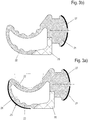
- in a) und b) Schnitte durch das Dichtungsprofil der
Fig. 1 , einmal mit einer Folie versehen und einmal nach dem Abziehen dieser Folie; - Fig. 4
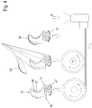
- eine schematische Darstellung von ausfeinaderfolgenden Schritten einer Herstellung des Dichtungsprofils aus
Fig. 1 bis 3 . -
Fig. 3a und 3b zeigen eine Dichtung 20, die in verschiedenster Weise auslegbar ist und deshalb als Mehrfunktionsdichtung bezeichnet werden kann. Bevorzugt wird diese Dichtung als eine Anschlagdichtung ausgestaltet. - Vorzugsweise sämtliche in
Fig. 2a) und b) sichtbaren Konturen und Elemente der Dichtung 20 erstrecken sich senkrecht zur Ebene derFig. 2a bzw.2b . Die Dichtung 20 ist somit als ein Dichtungsprofil ausgebildet, von dem gewünschte Dichtungen abgelängt werden. - Eine der Dichtungen ist in einem Falzbereich F zwischen einen Blendrahmen 200 und einem Flügelrahmen 300 in die Nut 201 eines Steges 202 des Blendrahmens 200 eingesetzt. Eine weitere der Dichtungen 20 ist in dem Falzbereich F zwischen dem Blendrahmen 200 und dem Flügelrahmen 300 hingegen in die Nut 301 eines Steges 302 des Flügelrahmens 300 des Flügels eingesetzt.
- Bei Schließen des Flügels wird der Flügel 300 zum Blendrahmen 200 bewegt und die Dichtungen 20 - die hier als Anschlagdichtungen wirken - werden aus einem unverformten Zustand der
Fig. 1b in den Zustand derFig. 1a ) verformt und umgekehrt. Dies ist beispielhaft inFig. 2a) und b) dargestellt. - Die Dichtung 20 weist einen Fußbereich 21 auf. Dieser Fußbereich 21 ist hier als ein hinterschnittener Steckfuß ausgebildet, der zum Einsetzen in eine hinterschnittene Nut nach Art der Nuten 201, 301 der
Fig. 1 ausgelegt sein kann. Der Fußbereich 21 könnte alternativ auch in anderer Weise ausgebildet sein. - Die Dichtung 20 (siehe auch
Fig. 3a und 3b ) weist jeweils einen sich an den Fußbereich 21 anschließenden Dichtungskörper auf. Dieser Dichtungskörper ist hier als ein Schlauchbereich 22, ausgebildet. Der Schlauchbereich 22 weist eine Dichtfläche 23 auf. - Die Dichtfläche 23 ist zumindest diejenige Fläche bzw. derjenige Flächenbereich des Schlauchbereiches (22), an welcher im montierten Zustand des Fußbereiches 21 an einem ersten Element (Blendrahmen 200 oder Flügelrahmen 300) - siehe
Fig. 1a - ein relativ dazu bewegliches zweites Element im geschlossenen Zustand des Fensters oder der Tür -Fig. 1b - bzw. in einer definierten Relativposition der beiden relativ zueinander beweglichen Elemente zur Anlage kommt (Flügelrahmen 300 oder Blendrahmen 200) bzw. kommen kann. - Der Schlauchbereich 22 kann vorzugsweise Einschnitte oder Aussparungen nach Art von Sicken 24 aufweisen, welche die Wandungen des Schlauchbereiches 22 aber nicht durchsetzen. Derart kann der Schlauchbereich 22 leichter beim Schließen und Öffnen des Flügels 300 verformt werden.
- Der Schlauchbereich 22 kann wie hier dargestellt sichelförmig gestaltet sein, so dass er bei einer Belastung (Kraft F in
Fig. 2 ), wie sie beim Schließen eines Flügels 300 Fensters auftritt, zur Seite hin ausweicht und verformt. Beim Schließen des Flügels 300 wird der Schlauchbereich 22 hier senkrecht zur Einsteckrichtung durch die einwirkende Kraft F gebogen bzw. verformt und somit parallel zur Kraft F kürzer und senkrecht zur Kraft F um eine Strecke L breiter. - Der Dichtungskörper bzw. der Schlauchbereich 22 und/oder der Fußbereich 21 sind ganz oder abschnittsweise aus wenigstens einem thermoplastischen Elastomer M extrudiert.
- Das thermoplastische Elastomer M kann in der extrudierten Dichtung 20 in einem geschäumten Zustand vorhanden bzw. ausgebildet sein oder in einem nicht geschäumten Zustand. So kann der überwiegende Teil der Dichtung 20 aus dem geschäumten thermoplastischen Elastomer bestehen. Zumindest besteht vorzugsweise die Dichtfläche 23 aus dem geschäumten thermoplastischen Elastomer.
- Ein Teil des Schlauch- und/oder des Fußbereiches 22 kann aber auch aus dem nicht geschäumten Kunststoffmaterial bestehen (vorzugsweise wiederum TPE). So kann insbesondere vorgesehen sein, zumindest einen Eckbereich 25 des Schlauchbereiches 22 aus dem nicht geschäumten Kunststoffmaterial zu bilden. Denn dies stabilisiert den Aufbau der ansonsten aus geschäumtem Material bestehenden Dichtung 20. Dabei kann bevorzugt vorgesehen sein, dass der Eckbereich 25 sich auf dem Blendrahmen 200 oder dem Flügelrahmen 300 abstützt. Der Eckbereich 25 aus nicht geschäumtem Material unterstützt, dass sich die Dichtung - siehe
Fig. 2 - beim Einwirken der Kraft F zu der Seite seitlich wegrollt bzw. in sich verformt, die dem Eckbereich gegenüberliegt. InFig. 2 ist der Eckbereich zur linken Seite vorgesehen (Fig. 2 unten) so dass sich der Schlauchbereich 22 beim Einwirken der Kraft F inFig. 2 nach rechts wegbiegt bzw. in sich verbiegt (Fig. 2 oben). Diese Wirkung wird durch die an dem Schlauchbereich 22 ebenfalls in die von dem Eckbereich abgewandte Richtung orientierten Sicken 24 unterstützt. - Damit eine möglichst gute Dichtwirkung auch nach vielfachem Öffnen und Schließen des Flügels 300 erzielt wird, sollte die Dichtfläche 23 möglichst glatt und wenig rau ausgebildet sein.
- Dazu ist es vorteilhaft, bei einem Extrudieren der Dichtung 21 wenigstens eine Folie 26 direkt beim Bilden bzw. der Extrudieren der Dichtung 20 im Bereich der Dichtfläche 23 mitlaufen zu lassen bzw. auf die sich bildende Dichtung 20 aufzubringen. Diese Folie besteht bevorzugt aus Polypropylen. Diese Folie 25 wird zumindest auf die Dichtfläche 23 aufgebracht. Es können auch optional eine oder mehrere weitere Folien 27 auf die Dichtung 20 aufgebracht werden (
Fig. 4 , rechter Teil). Auch diese bestehen vorzugsweise aus Polypropylen. Die weitere(n) Folien 26 werden vorzugsweise auf die Dichtung ein einem andere Bereich aufgebracht, beispielswiese auf den Fußbereich 21. Im Fußbereich 21 wirkt die Folie 27 im in die entsprechende Nut eingesteckten Zustand stabilisierend. Sie verbessert den Sitz der Dichtung 20 in der Nut. - Sodann wird die Folie 26 im Bereich der Dichtfläche 23 wieder entfernt (
Fig. 4 , mittlerer Teil) und die Dichtung 20 nach dem Entfernen auf eine Rolle aufgewickelt (Fig. 4 , rechter Teil). - Es ergibt sich folgendes vorteilhaftes Verfahren zum Herstellen einer Dichtung für ein Fenster oder eine Tür und zum Montieren an einem Fenster oder einer Tür:
- Der Schritt A) des Herstellungs- und Montageverfahrens umfasst ein Extrudieren einer Dichtung 20, wobei beim Extrudieren der Dichtung aus wenigstens einem thermoplastischen Elastomer wenigstens eine Folie 6 im Bereich der Dichtfläche 23 oder optional mehrere Folien 2627 auf die sich bildende Dichtung 20 aufgebracht wird/werden. Zumindest die Folie 26 auf der Dichtfläche 23 besteht bevorzugt aus Polypropylen.
- Entfernen - insbesondere Abziehen - der Folie 26 von dem Bereich der Dichtfläche 23.
- Montieren der Dichtung 20 an einem Blendrahmen 200 oder einem Flügelrahmen 300 eines Fensters oder einer Tür, insbesondere als Anschlagdichtung zwischen den relativ zueinander beweglichen Elementen Blendrahmen 200 und Flügelrahmen 300. Die Folie 26 hat eine deutlich glattere Oberfläche, als sie eine entsprechende Anlagefläche beim Extrudieren sonst aufweisen könnte. Dies bewirkt, dass auch die Oberfläche der Dichtung in diesen Bereichen, also mindestens im Bereich der Dichtfläche 23, eine sehr geringe Rauigkeit aufweist, so das dauerhaft eine sehr gute Dichtigkeit im Bereich der Dichtfläche 23 erreicht wird, die im Wesentlichen auch nach vielfachem Öffnen und Schließen erhalten bleibt.
Bezugszeichen Dichtung 20 Fußbereich 21 Schlauchbereich 22 Dichtfläche 23 Sicken 24 Eckbereich 25 Folie 26, 27 Blendrahmen 200 Flügelrahmen 300 Nuten 201 Nuten 301 Steg 202 Steges 302 Kraft F Strecke L thermoplastisches Elastomer M
Claims (8)
- Verfahren zum Herstellen einer Dichtung - eines Dichtungsprofils - für ein Fenster oder eine Tür mit einem Blendrahmen und einem Flügelrahmen und zum Montieren der Dichtung an dem Fenster oder der Tür, mit folgenden Schritten:Schritt A: thermoplastisches Extrudieren der Dichtung (20) mit einem Fußbereich (21) und einem Dichtungskörper, insbesondere als Schlauchbereich (22) ausgestaltet, der wenigstens eine Dichtfläche (23) aufweist, aus wenigstens einem bereitgestellten thermoplastischen Elastomer (TPE), wobei direkt beim Extrudieren der Dichtung an dem wenigstens einen thermoplastischen Elastomer wenigstens eine Folie (26) zumindest im Bereich der Dichtfläche (23) oder optional mehrere Folien (26, 27) auf der sich bildenden Dichtung (20) aufgebracht wird/werden;Schritt B: Entfernen - insbesondere Abziehen - der Folie (6) von der Dichtfläche (23); undSchritt C: Montieren der Dichtung (20) an dem Blendrahmen (200) oder dem Flügelrahmen (300) des Fensters oder der Tür.
- Verfahren nach Anspruch 1, dadurch gekennzeichnet, dass das Montieren der Dichtung (20) an einer Stelle erfolgt, wo sie als Anschlagdichtung zwischen den relativ zueinander beweglichen Elementen Blendrahmen (200) und Flügelrahmen (300) dient.
- Verfahren nach einem der vorstehenden Ansprüche, dadurch gekennzeichnet, dass das thermoplastische Elastomer zum Extrudieren der Dichtung im Schritt A) wenigstens im Bereich der Dichtfläche (23) zu einem Schaum verarbeitet wird.
- Verfahren nach einem der vorstehenden Ansprüche, dadurch gekennzeichnet, dass als die Folie (26, 27) eine Polypropylenfolie verwendet wird.
- Verfahren nach einem der vorstehenden Ansprüche, dadurch gekennzeichnet, dass an der Dichtung beim thermoplastischen Extrudieren des Schrittes A) wenigstens ein Bereich aus nicht geschäumten Material ausgebildet wird, insbesondere ein Eckbereich zum Aufliegen auf einem Fenster- oder Türprofil.
- Fenster oder Tür mit einem Blendrahmen (200) und wenigstens einem Flügelrahmen (300) und wenigstens einer als Anschlagdichtung dienenden Dichtung an dem Blendrahmen (200) oder dem Flügelrahmen (300), mit einer Dichtfläche (23) an welcher beim Extrudieren eine Folie (26) ausgebildet worden ist, die vor der Montage an dem Blend- oder Flügelrahmen wieder von der Dichtfläche entfernt worden ist.
- Dichtung für ein Fenster oder eine Tür nach Anspruch 6, dadurch gekennzeichnet, sie einen Fußbereich (21) und einen Dichtungskörper, insbesondere als Schlauchbereich (22) ausgestaltet, ist und die aus thermoplastischem Elastomer (TPE) durch thermoplastisches Extrudieren gebildet ist, mit einer Dichtfläche (23) an welcher beim Extrudieren eine Folie (26) ausgebildet worden ist, die vor der Montage an dem Blend- oder Flügelrahmen wieder von der Dichtfläche entfernt worden ist und/oder mit wenigstens einem Bereich aus nicht geschäumten Material, insbesondere einem Eckbereich zum Aufliegen auf einem Fenster- oder Türprofil.
- Verwendung einer Dichtung nach Anspruch 7 zum Einbau in ein Fenster oder eine Tür nach Anspruch 6.
Applications Claiming Priority (1)
| Application Number | Priority Date | Filing Date | Title |
|---|---|---|---|
| DE102018124170.4A DE102018124170A1 (de) | 2018-10-01 | 2018-10-01 | Verfahren zur Herstellung eines Dichtungsprofils für Fenster, Türen oder Fassaden und zum Montieren der Dichtung an der Tür |
Publications (2)
| Publication Number | Publication Date |
|---|---|
| EP3633132A1 true EP3633132A1 (de) | 2020-04-08 |
| EP3633132B1 EP3633132B1 (de) | 2021-07-07 |
Family
ID=68104416
Family Applications (1)
| Application Number | Title | Priority Date | Filing Date |
|---|---|---|---|
| EP19200390.3A Active EP3633132B1 (de) | 2018-10-01 | 2019-09-30 | Verfahren zur herstellung einer dichtung für fenster, türen oder fassaden und zum montieren der dichtung an der tür |
Country Status (2)
| Country | Link |
|---|---|
| EP (1) | EP3633132B1 (de) |
| DE (1) | DE102018124170A1 (de) |
Families Citing this family (2)
| Publication number | Priority date | Publication date | Assignee | Title |
|---|---|---|---|---|
| US11203896B2 (en) * | 2018-08-07 | 2021-12-21 | Endura Products, Llc | Entryway and weather strip for the same |
| DE102020106696A1 (de) | 2019-10-04 | 2021-04-08 | SCHÜCO International KG | Fenster mit einem Lüftungskanal |
Citations (5)
| Publication number | Priority date | Publication date | Assignee | Title |
|---|---|---|---|---|
| DE8907191U1 (de) * | 1989-06-12 | 1989-09-07 | Deventer Profile GmbH & Co KG, 13587 Berlin | Elastische Strangdichtung für Fenster, Türen od.dgl. |
| DE29512778U1 (de) | 1995-08-08 | 1996-12-12 | Semperit Ag Holding, Wien | Mehrzweckdichtung |
| DE19609226A1 (de) * | 1996-03-09 | 1997-09-11 | Oliver Eisele | Profildichtung für Fenster oder Türen |
| DE19750161A1 (de) * | 1997-11-12 | 1999-06-02 | Dipro Dichtungssysteme Gmbh | Strangförmige Universaldichtung für Fenster, Türen oder dergleichen |
| DE29814787U1 (de) | 1998-08-18 | 1999-12-30 | Semperit Ag Holding, Wien | Strangförmige Verglasungsdichtung |
Family Cites Families (3)
| Publication number | Priority date | Publication date | Assignee | Title |
|---|---|---|---|---|
| EP1136297A1 (de) * | 2000-03-21 | 2001-09-26 | DIPRO Dichtungssysteme GmbH | Verglasungsdichtung |
| DE10252595B3 (de) * | 2002-11-12 | 2004-05-06 | Metzeler Automotive Profile Systems Gmbh | Dichtung, insbesondere zum Abdichten einer Tür, einer Fensterscheibe oder des Dachs eines Kraftfahrzeugs |
| FR2869257B1 (fr) * | 2004-04-23 | 2007-10-12 | Rehau Sa | Procede automatise de fabrication d'une languette de prehension integree a une pellicule de protection d'une bande ou d'un cordon d'adhesif et profile extrude ou injecte comportant une telle languette |
-
2018
- 2018-10-01 DE DE102018124170.4A patent/DE102018124170A1/de not_active Withdrawn
-
2019
- 2019-09-30 EP EP19200390.3A patent/EP3633132B1/de active Active
Patent Citations (5)
| Publication number | Priority date | Publication date | Assignee | Title |
|---|---|---|---|---|
| DE8907191U1 (de) * | 1989-06-12 | 1989-09-07 | Deventer Profile GmbH & Co KG, 13587 Berlin | Elastische Strangdichtung für Fenster, Türen od.dgl. |
| DE29512778U1 (de) | 1995-08-08 | 1996-12-12 | Semperit Ag Holding, Wien | Mehrzweckdichtung |
| DE19609226A1 (de) * | 1996-03-09 | 1997-09-11 | Oliver Eisele | Profildichtung für Fenster oder Türen |
| DE19750161A1 (de) * | 1997-11-12 | 1999-06-02 | Dipro Dichtungssysteme Gmbh | Strangförmige Universaldichtung für Fenster, Türen oder dergleichen |
| DE29814787U1 (de) | 1998-08-18 | 1999-12-30 | Semperit Ag Holding, Wien | Strangförmige Verglasungsdichtung |
Also Published As
| Publication number | Publication date |
|---|---|
| EP3633132B1 (de) | 2021-07-07 |
| DE102018124170A1 (de) | 2020-04-02 |
Similar Documents
| Publication | Publication Date | Title |
|---|---|---|
| EP3633132B1 (de) | Verfahren zur herstellung einer dichtung für fenster, türen oder fassaden und zum montieren der dichtung an der tür | |
| EP3438395B1 (de) | Fensterrahmensystem | |
| AT413293B (de) | Schiebeelement-dichtung | |
| EP2363567A2 (de) | Rahmen eines Kunststofffensters oder einer Kunststofftür sowie Mitteldichtung hierfür | |
| DE2619707C3 (de) | Verbundprofil, bestehend aus zwei parallelen Metallteilen und einem Isolationsprofil | |
| EP0757152B1 (de) | Strangförmiges Dichtungsprofil | |
| EP0310548B1 (de) | Rolladen oder Rolltor | |
| DE19719474A1 (de) | Strangdichtung | |
| EP2792520B1 (de) | Dichtungsprofil und Türanordnung mit einem solchen Dichtungsprofil | |
| DE19828186A1 (de) | Gelenkeinrichtung, insbesondere für Rolladen- oder Falttürelemente, und Roll- oder Faltvorhang | |
| EP3135962B1 (de) | Dichtelement | |
| EP3680438B1 (de) | Anordnung aus einem rahmenprofil und einem dichtprofil für einen fenster- oder türrahmen | |
| EP3848550B1 (de) | Fenster mit einem lüftungskanal | |
| WO2024240377A1 (de) | Dichtungsprofil und anordnung des dichtungsprofils zwischen einer brüstung und einer fensterscheibe im dichtungsfreien design | |
| DE202014104110U1 (de) | Türdichtungsvorrichtung, Türdichtungssystem und Türflügel für ein Schienenfahrzeug | |
| EP3140484B1 (de) | Verbundprofil für türen, fenster oder fassadenelemente | |
| WO2007134724A1 (de) | Türdichtungsprofil | |
| EP0828055A2 (de) | Strangförmige Dichtung für Fenster oder dergleichen Bauteile | |
| DE202007006738U1 (de) | Türdichtungsprofil | |
| EP3569807B1 (de) | Fugenleiste | |
| EP4001575A1 (de) | Abstandshalter | |
| EP1105613A1 (de) | Strangförmige verglasungsdichtung | |
| EP3988757B1 (de) | Strangdichtung aus elastischem schaummaterial | |
| EP0635620B1 (de) | Profil mit offenem Querschnitt insbesondere für Rolläden | |
| DE29719603U1 (de) | Strangförmiges Dichtungsprofil |
Legal Events
| Date | Code | Title | Description |
|---|---|---|---|
| PUAI | Public reference made under article 153(3) epc to a published international application that has entered the european phase |
Free format text: ORIGINAL CODE: 0009012 |
|
| STAA | Information on the status of an ep patent application or granted ep patent |
Free format text: STATUS: THE APPLICATION HAS BEEN PUBLISHED |
|
| AK | Designated contracting states |
Kind code of ref document: A1 Designated state(s): AL AT BE BG CH CY CZ DE DK EE ES FI FR GB GR HR HU IE IS IT LI LT LU LV MC MK MT NL NO PL PT RO RS SE SI SK SM TR |
|
| AX | Request for extension of the european patent |
Extension state: BA ME |
|
| STAA | Information on the status of an ep patent application or granted ep patent |
Free format text: STATUS: REQUEST FOR EXAMINATION WAS MADE |
|
| 17P | Request for examination filed |
Effective date: 20201006 |
|
| RBV | Designated contracting states (corrected) |
Designated state(s): AL AT BE BG CH CY CZ DE DK EE ES FI FR GB GR HR HU IE IS IT LI LT LU LV MC MK MT NL NO PL PT RO RS SE SI SK SM TR |
|
| GRAP | Despatch of communication of intention to grant a patent |
Free format text: ORIGINAL CODE: EPIDOSNIGR1 |
|
| STAA | Information on the status of an ep patent application or granted ep patent |
Free format text: STATUS: GRANT OF PATENT IS INTENDED |
|
| INTG | Intention to grant announced |
Effective date: 20210119 |
|
| GRAS | Grant fee paid |
Free format text: ORIGINAL CODE: EPIDOSNIGR3 |
|
| GRAA | (expected) grant |
Free format text: ORIGINAL CODE: 0009210 |
|
| STAA | Information on the status of an ep patent application or granted ep patent |
Free format text: STATUS: THE PATENT HAS BEEN GRANTED |
|
| AK | Designated contracting states |
Kind code of ref document: B1 Designated state(s): AL AT BE BG CH CY CZ DE DK EE ES FI FR GB GR HR HU IE IS IT LI LT LU LV MC MK MT NL NO PL PT RO RS SE SI SK SM TR |
|
| RAP1 | Party data changed (applicant data changed or rights of an application transferred) |
Owner name: IEB GUMMITECHNIK EISELE & CO. GMBH |
|
| REG | Reference to a national code |
Ref country code: GB Ref legal event code: FG4D Free format text: NOT ENGLISH |
|
| REG | Reference to a national code |
Ref country code: AT Ref legal event code: REF Ref document number: 1408762 Country of ref document: AT Kind code of ref document: T Effective date: 20210715 |
|
| REG | Reference to a national code |
Ref country code: DE Ref legal event code: R096 Ref document number: 502019001774 Country of ref document: DE |
|
| REG | Reference to a national code |
Ref country code: IE Ref legal event code: FG4D Free format text: LANGUAGE OF EP DOCUMENT: GERMAN |
|
| REG | Reference to a national code |
Ref country code: LT Ref legal event code: MG9D |
|
| REG | Reference to a national code |
Ref country code: NL Ref legal event code: MP Effective date: 20210707 |
|
| PG25 | Lapsed in a contracting state [announced via postgrant information from national office to epo] |
Ref country code: BG Free format text: LAPSE BECAUSE OF FAILURE TO SUBMIT A TRANSLATION OF THE DESCRIPTION OR TO PAY THE FEE WITHIN THE PRESCRIBED TIME-LIMIT Effective date: 20211007 Ref country code: LT Free format text: LAPSE BECAUSE OF FAILURE TO SUBMIT A TRANSLATION OF THE DESCRIPTION OR TO PAY THE FEE WITHIN THE PRESCRIBED TIME-LIMIT Effective date: 20210707 Ref country code: HR Free format text: LAPSE BECAUSE OF FAILURE TO SUBMIT A TRANSLATION OF THE DESCRIPTION OR TO PAY THE FEE WITHIN THE PRESCRIBED TIME-LIMIT Effective date: 20210707 Ref country code: PT Free format text: LAPSE BECAUSE OF FAILURE TO SUBMIT A TRANSLATION OF THE DESCRIPTION OR TO PAY THE FEE WITHIN THE PRESCRIBED TIME-LIMIT Effective date: 20211108 Ref country code: NL Free format text: LAPSE BECAUSE OF FAILURE TO SUBMIT A TRANSLATION OF THE DESCRIPTION OR TO PAY THE FEE WITHIN THE PRESCRIBED TIME-LIMIT Effective date: 20210707 Ref country code: NO Free format text: LAPSE BECAUSE OF FAILURE TO SUBMIT A TRANSLATION OF THE DESCRIPTION OR TO PAY THE FEE WITHIN THE PRESCRIBED TIME-LIMIT Effective date: 20211007 Ref country code: RS Free format text: LAPSE BECAUSE OF FAILURE TO SUBMIT A TRANSLATION OF THE DESCRIPTION OR TO PAY THE FEE WITHIN THE PRESCRIBED TIME-LIMIT Effective date: 20210707 Ref country code: SE Free format text: LAPSE BECAUSE OF FAILURE TO SUBMIT A TRANSLATION OF THE DESCRIPTION OR TO PAY THE FEE WITHIN THE PRESCRIBED TIME-LIMIT Effective date: 20210707 Ref country code: FI Free format text: LAPSE BECAUSE OF FAILURE TO SUBMIT A TRANSLATION OF THE DESCRIPTION OR TO PAY THE FEE WITHIN THE PRESCRIBED TIME-LIMIT Effective date: 20210707 Ref country code: ES Free format text: LAPSE BECAUSE OF FAILURE TO SUBMIT A TRANSLATION OF THE DESCRIPTION OR TO PAY THE FEE WITHIN THE PRESCRIBED TIME-LIMIT Effective date: 20210707 |
|
| PG25 | Lapsed in a contracting state [announced via postgrant information from national office to epo] |
Ref country code: PL Free format text: LAPSE BECAUSE OF FAILURE TO SUBMIT A TRANSLATION OF THE DESCRIPTION OR TO PAY THE FEE WITHIN THE PRESCRIBED TIME-LIMIT Effective date: 20210707 Ref country code: LV Free format text: LAPSE BECAUSE OF FAILURE TO SUBMIT A TRANSLATION OF THE DESCRIPTION OR TO PAY THE FEE WITHIN THE PRESCRIBED TIME-LIMIT Effective date: 20210707 Ref country code: GR Free format text: LAPSE BECAUSE OF FAILURE TO SUBMIT A TRANSLATION OF THE DESCRIPTION OR TO PAY THE FEE WITHIN THE PRESCRIBED TIME-LIMIT Effective date: 20211008 |
|
| REG | Reference to a national code |
Ref country code: DE Ref legal event code: R097 Ref document number: 502019001774 Country of ref document: DE |
|
| PG25 | Lapsed in a contracting state [announced via postgrant information from national office to epo] |
Ref country code: DK Free format text: LAPSE BECAUSE OF FAILURE TO SUBMIT A TRANSLATION OF THE DESCRIPTION OR TO PAY THE FEE WITHIN THE PRESCRIBED TIME-LIMIT Effective date: 20210707 |
|
| PLBE | No opposition filed within time limit |
Free format text: ORIGINAL CODE: 0009261 |
|
| STAA | Information on the status of an ep patent application or granted ep patent |
Free format text: STATUS: NO OPPOSITION FILED WITHIN TIME LIMIT |
|
| REG | Reference to a national code |
Ref country code: BE Ref legal event code: MM Effective date: 20210930 |
|
| PG25 | Lapsed in a contracting state [announced via postgrant information from national office to epo] |
Ref country code: SM Free format text: LAPSE BECAUSE OF FAILURE TO SUBMIT A TRANSLATION OF THE DESCRIPTION OR TO PAY THE FEE WITHIN THE PRESCRIBED TIME-LIMIT Effective date: 20210707 Ref country code: SK Free format text: LAPSE BECAUSE OF FAILURE TO SUBMIT A TRANSLATION OF THE DESCRIPTION OR TO PAY THE FEE WITHIN THE PRESCRIBED TIME-LIMIT Effective date: 20210707 Ref country code: RO Free format text: LAPSE BECAUSE OF FAILURE TO SUBMIT A TRANSLATION OF THE DESCRIPTION OR TO PAY THE FEE WITHIN THE PRESCRIBED TIME-LIMIT Effective date: 20210707 Ref country code: MC Free format text: LAPSE BECAUSE OF FAILURE TO SUBMIT A TRANSLATION OF THE DESCRIPTION OR TO PAY THE FEE WITHIN THE PRESCRIBED TIME-LIMIT Effective date: 20210707 Ref country code: EE Free format text: LAPSE BECAUSE OF FAILURE TO SUBMIT A TRANSLATION OF THE DESCRIPTION OR TO PAY THE FEE WITHIN THE PRESCRIBED TIME-LIMIT Effective date: 20210707 Ref country code: CZ Free format text: LAPSE BECAUSE OF FAILURE TO SUBMIT A TRANSLATION OF THE DESCRIPTION OR TO PAY THE FEE WITHIN THE PRESCRIBED TIME-LIMIT Effective date: 20210707 Ref country code: AL Free format text: LAPSE BECAUSE OF FAILURE TO SUBMIT A TRANSLATION OF THE DESCRIPTION OR TO PAY THE FEE WITHIN THE PRESCRIBED TIME-LIMIT Effective date: 20210707 |
|
| 26N | No opposition filed |
Effective date: 20220408 |
|
| PG25 | Lapsed in a contracting state [announced via postgrant information from national office to epo] |
Ref country code: LU Free format text: LAPSE BECAUSE OF NON-PAYMENT OF DUE FEES Effective date: 20210930 Ref country code: IT Free format text: LAPSE BECAUSE OF FAILURE TO SUBMIT A TRANSLATION OF THE DESCRIPTION OR TO PAY THE FEE WITHIN THE PRESCRIBED TIME-LIMIT Effective date: 20210707 Ref country code: IE Free format text: LAPSE BECAUSE OF NON-PAYMENT OF DUE FEES Effective date: 20210930 Ref country code: BE Free format text: LAPSE BECAUSE OF NON-PAYMENT OF DUE FEES Effective date: 20210930 |
|
| PG25 | Lapsed in a contracting state [announced via postgrant information from national office to epo] |
Ref country code: CY Free format text: LAPSE BECAUSE OF FAILURE TO SUBMIT A TRANSLATION OF THE DESCRIPTION OR TO PAY THE FEE WITHIN THE PRESCRIBED TIME-LIMIT Effective date: 20210707 |
|
| PG25 | Lapsed in a contracting state [announced via postgrant information from national office to epo] |
Ref country code: HU Free format text: LAPSE BECAUSE OF FAILURE TO SUBMIT A TRANSLATION OF THE DESCRIPTION OR TO PAY THE FEE WITHIN THE PRESCRIBED TIME-LIMIT; INVALID AB INITIO Effective date: 20190930 |
|
| PG25 | Lapsed in a contracting state [announced via postgrant information from national office to epo] |
Ref country code: MK Free format text: LAPSE BECAUSE OF FAILURE TO SUBMIT A TRANSLATION OF THE DESCRIPTION OR TO PAY THE FEE WITHIN THE PRESCRIBED TIME-LIMIT Effective date: 20210707 |
|
| GBPC | Gb: european patent ceased through non-payment of renewal fee |
Effective date: 20230930 |
|
| PG25 | Lapsed in a contracting state [announced via postgrant information from national office to epo] |
Ref country code: TR Free format text: LAPSE BECAUSE OF FAILURE TO SUBMIT A TRANSLATION OF THE DESCRIPTION OR TO PAY THE FEE WITHIN THE PRESCRIBED TIME-LIMIT Effective date: 20210707 |
|
| PG25 | Lapsed in a contracting state [announced via postgrant information from national office to epo] |
Ref country code: GB Free format text: LAPSE BECAUSE OF NON-PAYMENT OF DUE FEES Effective date: 20230930 |
|
| PG25 | Lapsed in a contracting state [announced via postgrant information from national office to epo] |
Ref country code: GB Free format text: LAPSE BECAUSE OF NON-PAYMENT OF DUE FEES Effective date: 20230930 |
|
| PG25 | Lapsed in a contracting state [announced via postgrant information from national office to epo] |
Ref country code: MT Free format text: LAPSE BECAUSE OF FAILURE TO SUBMIT A TRANSLATION OF THE DESCRIPTION OR TO PAY THE FEE WITHIN THE PRESCRIBED TIME-LIMIT Effective date: 20210707 |
|
| REG | Reference to a national code |
Ref country code: CH Ref legal event code: U11 Free format text: ST27 STATUS EVENT CODE: U-0-0-U10-U11 (AS PROVIDED BY THE NATIONAL OFFICE) Effective date: 20251001 |
|
| PGFP | Annual fee paid to national office [announced via postgrant information from national office to epo] |
Ref country code: DE Payment date: 20250625 Year of fee payment: 7 |
|
| PGFP | Annual fee paid to national office [announced via postgrant information from national office to epo] |
Ref country code: FR Payment date: 20250925 Year of fee payment: 7 Ref country code: AT Payment date: 20250930 Year of fee payment: 7 |
|
| PGFP | Annual fee paid to national office [announced via postgrant information from national office to epo] |
Ref country code: CH Payment date: 20251001 Year of fee payment: 7 |