EP3632885A1 - Verfahren zur hydroformylierung von kurzkettigen olefinen in der gasphase - Google Patents
Verfahren zur hydroformylierung von kurzkettigen olefinen in der gasphase Download PDFInfo
- Publication number
- EP3632885A1 EP3632885A1 EP19200442.2A EP19200442A EP3632885A1 EP 3632885 A1 EP3632885 A1 EP 3632885A1 EP 19200442 A EP19200442 A EP 19200442A EP 3632885 A1 EP3632885 A1 EP 3632885A1
- Authority
- EP
- European Patent Office
- Prior art keywords
- ceramic
- support
- hydroformylation
- carbide
- catalyst system
- Prior art date
- Legal status (The legal status is an assumption and is not a legal conclusion. Google has not performed a legal analysis and makes no representation as to the accuracy of the status listed.)
- Pending
Links
- 238000007037 hydroformylation reaction Methods 0.000 title claims abstract description 40
- 238000000034 method Methods 0.000 title claims abstract description 35
- 150000001336 alkenes Chemical class 0.000 title claims abstract description 32
- 239000003054 catalyst Substances 0.000 claims abstract description 94
- 229910010293 ceramic material Inorganic materials 0.000 claims abstract description 28
- 230000008569 process Effects 0.000 claims abstract description 16
- 239000000203 mixture Substances 0.000 claims description 54
- 230000015572 biosynthetic process Effects 0.000 claims description 24
- 239000000919 ceramic Substances 0.000 claims description 24
- 238000006243 chemical reaction Methods 0.000 claims description 23
- 239000007789 gas Substances 0.000 claims description 22
- 239000002608 ionic liquid Substances 0.000 claims description 22
- -1 amine compound Chemical class 0.000 claims description 20
- 239000003381 stabilizer Substances 0.000 claims description 16
- 238000003786 synthesis reaction Methods 0.000 claims description 15
- 239000003446 ligand Substances 0.000 claims description 14
- OAICVXFJPJFONN-UHFFFAOYSA-N Phosphorus Chemical compound [P] OAICVXFJPJFONN-UHFFFAOYSA-N 0.000 claims description 8
- 229910052698 phosphorus Inorganic materials 0.000 claims description 8
- 239000011574 phosphorus Substances 0.000 claims description 8
- 229910052751 metal Inorganic materials 0.000 claims description 5
- 239000002184 metal Substances 0.000 claims description 5
- 229910010271 silicon carbide Inorganic materials 0.000 claims description 5
- HBMJWWWQQXIZIP-UHFFFAOYSA-N silicon carbide Chemical compound [Si+]#[C-] HBMJWWWQQXIZIP-UHFFFAOYSA-N 0.000 claims description 5
- BPQQTUXANYXVAA-UHFFFAOYSA-N Orthosilicate Chemical compound [O-][Si]([O-])([O-])[O-] BPQQTUXANYXVAA-UHFFFAOYSA-N 0.000 claims description 4
- GWEVSGVZZGPLCZ-UHFFFAOYSA-N Titan oxide Chemical compound O=[Ti]=O GWEVSGVZZGPLCZ-UHFFFAOYSA-N 0.000 claims description 4
- XLOMVQKBTHCTTD-UHFFFAOYSA-N Zinc monoxide Chemical compound [Zn]=O XLOMVQKBTHCTTD-UHFFFAOYSA-N 0.000 claims description 4
- 229910052574 oxide ceramic Inorganic materials 0.000 claims description 4
- 239000011224 oxide ceramic Substances 0.000 claims description 4
- 229910021332 silicide Inorganic materials 0.000 claims description 4
- FVBUAEGBCNSCDD-UHFFFAOYSA-N silicide(4-) Chemical compound [Si-4] FVBUAEGBCNSCDD-UHFFFAOYSA-N 0.000 claims description 4
- 229910052580 B4C Inorganic materials 0.000 claims description 3
- INAHAJYZKVIDIZ-UHFFFAOYSA-N boron carbide Chemical compound B12B3B4C32B41 INAHAJYZKVIDIZ-UHFFFAOYSA-N 0.000 claims description 3
- 150000004767 nitrides Chemical class 0.000 claims description 3
- 230000000737 periodic effect Effects 0.000 claims description 3
- UONOETXJSWQNOL-UHFFFAOYSA-N tungsten carbide Chemical compound [W+]#[C-] UONOETXJSWQNOL-UHFFFAOYSA-N 0.000 claims description 3
- RKMGAJGJIURJSJ-UHFFFAOYSA-N 2,2,6,6-tetramethylpiperidine Chemical group CC1(C)CCCC(C)(C)N1 RKMGAJGJIURJSJ-UHFFFAOYSA-N 0.000 claims description 2
- 229910000505 Al2TiO5 Inorganic materials 0.000 claims description 2
- 229910052582 BN Inorganic materials 0.000 claims description 2
- PZNSFCLAULLKQX-UHFFFAOYSA-N Boron nitride Chemical compound N#B PZNSFCLAULLKQX-UHFFFAOYSA-N 0.000 claims description 2
- 229910052581 Si3N4 Inorganic materials 0.000 claims description 2
- 229910000323 aluminium silicate Inorganic materials 0.000 claims description 2
- 229910002113 barium titanate Inorganic materials 0.000 claims description 2
- JRPBQTZRNDNNOP-UHFFFAOYSA-N barium titanate Chemical compound [Ba+2].[Ba+2].[O-][Ti]([O-])([O-])[O-] JRPBQTZRNDNNOP-UHFFFAOYSA-N 0.000 claims description 2
- 239000000440 bentonite Substances 0.000 claims description 2
- 229910000278 bentonite Inorganic materials 0.000 claims description 2
- SVPXDRXYRYOSEX-UHFFFAOYSA-N bentoquatam Chemical compound O.O=[Si]=O.O=[Al]O[Al]=O SVPXDRXYRYOSEX-UHFFFAOYSA-N 0.000 claims description 2
- YXTPWUNVHCYOSP-UHFFFAOYSA-N bis($l^{2}-silanylidene)molybdenum Chemical compound [Si]=[Mo]=[Si] YXTPWUNVHCYOSP-UHFFFAOYSA-N 0.000 claims description 2
- PMHQVHHXPFUNSP-UHFFFAOYSA-M copper(1+);methylsulfanylmethane;bromide Chemical compound Br[Cu].CSC PMHQVHHXPFUNSP-UHFFFAOYSA-M 0.000 claims description 2
- HNPSIPDUKPIQMN-UHFFFAOYSA-N dioxosilane;oxo(oxoalumanyloxy)alumane Chemical compound O=[Si]=O.O=[Al]O[Al]=O HNPSIPDUKPIQMN-UHFFFAOYSA-N 0.000 claims description 2
- UQSXHKLRYXJYBZ-UHFFFAOYSA-N iron oxide Inorganic materials [Fe]=O UQSXHKLRYXJYBZ-UHFFFAOYSA-N 0.000 claims description 2
- 235000013980 iron oxide Nutrition 0.000 claims description 2
- VBMVTYDPPZVILR-UHFFFAOYSA-N iron(2+);oxygen(2-) Chemical class [O-2].[Fe+2] VBMVTYDPPZVILR-UHFFFAOYSA-N 0.000 claims description 2
- HCWCAKKEBCNQJP-UHFFFAOYSA-N magnesium orthosilicate Chemical compound [Mg+2].[Mg+2].[O-][Si]([O-])([O-])[O-] HCWCAKKEBCNQJP-UHFFFAOYSA-N 0.000 claims description 2
- 239000000391 magnesium silicate Substances 0.000 claims description 2
- 229910052919 magnesium silicate Inorganic materials 0.000 claims description 2
- 235000019792 magnesium silicate Nutrition 0.000 claims description 2
- 125000004430 oxygen atom Chemical group O* 0.000 claims description 2
- RVTZCBVAJQQJTK-UHFFFAOYSA-N oxygen(2-);zirconium(4+) Chemical compound [O-2].[O-2].[Zr+4] RVTZCBVAJQQJTK-UHFFFAOYSA-N 0.000 claims description 2
- AABBHSMFGKYLKE-SNAWJCMRSA-N propan-2-yl (e)-but-2-enoate Chemical compound C\C=C\C(=O)OC(C)C AABBHSMFGKYLKE-SNAWJCMRSA-N 0.000 claims description 2
- HQVNEWCFYHHQES-UHFFFAOYSA-N silicon nitride Chemical compound N12[Si]34N5[Si]62N3[Si]51N64 HQVNEWCFYHHQES-UHFFFAOYSA-N 0.000 claims description 2
- 239000004408 titanium dioxide Substances 0.000 claims description 2
- 239000011787 zinc oxide Substances 0.000 claims description 2
- 229910001928 zirconium oxide Inorganic materials 0.000 claims description 2
- 229910000859 α-Fe Inorganic materials 0.000 claims description 2
- FRWYFWZENXDZMU-UHFFFAOYSA-N 2-iodoquinoline Chemical compound C1=CC=CC2=NC(I)=CC=C21 FRWYFWZENXDZMU-UHFFFAOYSA-N 0.000 claims 1
- LTPBRCUWZOMYOC-UHFFFAOYSA-N beryllium oxide Inorganic materials O=[Be] LTPBRCUWZOMYOC-UHFFFAOYSA-N 0.000 claims 1
- 229910021344 molybdenum silicide Inorganic materials 0.000 claims 1
- 239000002904 solvent Substances 0.000 description 27
- 239000000047 product Substances 0.000 description 24
- 239000000243 solution Substances 0.000 description 24
- 238000000926 separation method Methods 0.000 description 17
- 150000001299 aldehydes Chemical class 0.000 description 16
- 239000011148 porous material Substances 0.000 description 16
- 239000000463 material Substances 0.000 description 15
- IJGRMHOSHXDMSA-UHFFFAOYSA-N Atomic nitrogen Chemical compound N#N IJGRMHOSHXDMSA-UHFFFAOYSA-N 0.000 description 12
- 125000000383 tetramethylene group Chemical group [H]C([H])([*:1])C([H])([H])C([H])([H])C([H])([H])[*:2] 0.000 description 12
- 230000000694 effects Effects 0.000 description 11
- 239000011261 inert gas Substances 0.000 description 11
- 239000007788 liquid Substances 0.000 description 11
- YMWUJEATGCHHMB-UHFFFAOYSA-N Dichloromethane Chemical compound ClCCl YMWUJEATGCHHMB-UHFFFAOYSA-N 0.000 description 9
- 238000011065 in-situ storage Methods 0.000 description 9
- 239000012071 phase Substances 0.000 description 9
- VXNZUUAINFGPBY-UHFFFAOYSA-N 1-Butene Chemical compound CCC=C VXNZUUAINFGPBY-UHFFFAOYSA-N 0.000 description 8
- 238000005470 impregnation Methods 0.000 description 7
- IJDNQMDRQITEOD-UHFFFAOYSA-N n-butane Chemical compound CCCC IJDNQMDRQITEOD-UHFFFAOYSA-N 0.000 description 7
- 239000010948 rhodium Substances 0.000 description 7
- 239000007787 solid Substances 0.000 description 7
- 230000007306 turnover Effects 0.000 description 7
- 239000006227 byproduct Substances 0.000 description 6
- 229910017052 cobalt Inorganic materials 0.000 description 6
- 239000010941 cobalt Substances 0.000 description 6
- GUTLYIVDDKVIGB-UHFFFAOYSA-N cobalt atom Chemical compound [Co] GUTLYIVDDKVIGB-UHFFFAOYSA-N 0.000 description 6
- ZUOUZKKEUPVFJK-UHFFFAOYSA-N diphenyl Chemical group C1=CC=CC=C1C1=CC=CC=C1 ZUOUZKKEUPVFJK-UHFFFAOYSA-N 0.000 description 6
- 238000004519 manufacturing process Methods 0.000 description 6
- 229910052757 nitrogen Inorganic materials 0.000 description 6
- 229910052703 rhodium Inorganic materials 0.000 description 6
- MHOVAHRLVXNVSD-UHFFFAOYSA-N rhodium atom Chemical compound [Rh] MHOVAHRLVXNVSD-UHFFFAOYSA-N 0.000 description 6
- 239000000126 substance Substances 0.000 description 6
- 125000004209 (C1-C8) alkyl group Chemical group 0.000 description 5
- 150000001335 aliphatic alkanes Chemical class 0.000 description 5
- 235000013844 butane Nutrition 0.000 description 5
- 238000011049 filling Methods 0.000 description 5
- 238000011010 flushing procedure Methods 0.000 description 5
- 150000003254 radicals Chemical class 0.000 description 5
- 125000004191 (C1-C6) alkoxy group Chemical group 0.000 description 4
- 239000004215 Carbon black (E152) Substances 0.000 description 4
- VQTUBCCKSQIDNK-UHFFFAOYSA-N Isobutene Chemical compound CC(C)=C VQTUBCCKSQIDNK-UHFFFAOYSA-N 0.000 description 4
- 125000004103 aminoalkyl group Chemical group 0.000 description 4
- 238000009833 condensation Methods 0.000 description 4
- 230000005494 condensation Effects 0.000 description 4
- 238000002474 experimental method Methods 0.000 description 4
- 238000004817 gas chromatography Methods 0.000 description 4
- 229930195733 hydrocarbon Natural products 0.000 description 4
- 150000002430 hydrocarbons Chemical class 0.000 description 4
- 238000009434 installation Methods 0.000 description 4
- NNPPMTNAJDCUHE-UHFFFAOYSA-N isobutane Chemical compound CC(C)C NNPPMTNAJDCUHE-UHFFFAOYSA-N 0.000 description 4
- QWTDNUCVQCZILF-UHFFFAOYSA-N isopentane Chemical compound CCC(C)C QWTDNUCVQCZILF-UHFFFAOYSA-N 0.000 description 4
- JRZJOMJEPLMPRA-UHFFFAOYSA-N olefin Natural products CCCCCCCC=C JRZJOMJEPLMPRA-UHFFFAOYSA-N 0.000 description 4
- 238000010926 purge Methods 0.000 description 4
- 238000012360 testing method Methods 0.000 description 4
- 229910052723 transition metal Inorganic materials 0.000 description 4
- 150000003624 transition metals Chemical class 0.000 description 4
- WEVYAHXRMPXWCK-UHFFFAOYSA-N Acetonitrile Chemical compound CC#N WEVYAHXRMPXWCK-UHFFFAOYSA-N 0.000 description 3
- RTZKZFJDLAIYFH-UHFFFAOYSA-N Diethyl ether Chemical compound CCOCC RTZKZFJDLAIYFH-UHFFFAOYSA-N 0.000 description 3
- XEKOWRVHYACXOJ-UHFFFAOYSA-N Ethyl acetate Chemical compound CCOC(C)=O XEKOWRVHYACXOJ-UHFFFAOYSA-N 0.000 description 3
- 230000008901 benefit Effects 0.000 description 3
- 239000001273 butane Substances 0.000 description 3
- 150000001875 compounds Chemical class 0.000 description 3
- 230000009849 deactivation Effects 0.000 description 3
- 238000001704 evaporation Methods 0.000 description 3
- 239000002638 heterogeneous catalyst Substances 0.000 description 3
- 238000011835 investigation Methods 0.000 description 3
- 239000007791 liquid phase Substances 0.000 description 3
- 238000002156 mixing Methods 0.000 description 3
- OFBQJSOFQDEBGM-UHFFFAOYSA-N n-pentane Natural products CCCCC OFBQJSOFQDEBGM-UHFFFAOYSA-N 0.000 description 3
- 239000002243 precursor Substances 0.000 description 3
- 238000002360 preparation method Methods 0.000 description 3
- 230000008929 regeneration Effects 0.000 description 3
- 238000011069 regeneration method Methods 0.000 description 3
- XLYOFNOQVPJJNP-UHFFFAOYSA-N water Substances O XLYOFNOQVPJJNP-UHFFFAOYSA-N 0.000 description 3
- XKRFYHLGVUSROY-UHFFFAOYSA-N Argon Chemical compound [Ar] XKRFYHLGVUSROY-UHFFFAOYSA-N 0.000 description 2
- XEEYBQQBJWHFJM-UHFFFAOYSA-N Iron Chemical compound [Fe] XEEYBQQBJWHFJM-UHFFFAOYSA-N 0.000 description 2
- QQONPFPTGQHPMA-UHFFFAOYSA-N Propene Chemical compound CC=C QQONPFPTGQHPMA-UHFFFAOYSA-N 0.000 description 2
- 229910004298 SiO 2 Inorganic materials 0.000 description 2
- VYPSYNLAJGMNEJ-UHFFFAOYSA-N Silicium dioxide Chemical compound O=[Si]=O VYPSYNLAJGMNEJ-UHFFFAOYSA-N 0.000 description 2
- WYURNTSHIVDZCO-UHFFFAOYSA-N Tetrahydrofuran Chemical compound C1CCOC1 WYURNTSHIVDZCO-UHFFFAOYSA-N 0.000 description 2
- 230000004913 activation Effects 0.000 description 2
- 125000000217 alkyl group Chemical group 0.000 description 2
- 235000010290 biphenyl Nutrition 0.000 description 2
- XITRBUPOXXBIJN-UHFFFAOYSA-N bis(2,2,6,6-tetramethylpiperidin-4-yl) decanedioate Chemical compound C1C(C)(C)NC(C)(C)CC1OC(=O)CCCCCCCCC(=O)OC1CC(C)(C)NC(C)(C)C1 XITRBUPOXXBIJN-UHFFFAOYSA-N 0.000 description 2
- LRESCJAINPKJTO-UHFFFAOYSA-N bis(trifluoromethylsulfonyl)azanide;1-ethyl-3-methylimidazol-3-ium Chemical compound CCN1C=C[N+](C)=C1.FC(F)(F)S(=O)(=O)[N-]S(=O)(=O)C(F)(F)F LRESCJAINPKJTO-UHFFFAOYSA-N 0.000 description 2
- 238000009835 boiling Methods 0.000 description 2
- IAQRGUVFOMOMEM-UHFFFAOYSA-N but-2-ene Chemical compound CC=CC IAQRGUVFOMOMEM-UHFFFAOYSA-N 0.000 description 2
- GGRQQHADVSXBQN-FGSKAQBVSA-N carbon monoxide;(z)-4-hydroxypent-3-en-2-one;rhodium Chemical compound [Rh].[O+]#[C-].[O+]#[C-].C\C(O)=C\C(C)=O GGRQQHADVSXBQN-FGSKAQBVSA-N 0.000 description 2
- 239000012876 carrier material Substances 0.000 description 2
- 150000001768 cations Chemical class 0.000 description 2
- IAQRGUVFOMOMEM-ARJAWSKDSA-N cis-but-2-ene Chemical compound C\C=C/C IAQRGUVFOMOMEM-ARJAWSKDSA-N 0.000 description 2
- 238000000354 decomposition reaction Methods 0.000 description 2
- 238000003618 dip coating Methods 0.000 description 2
- 238000004821 distillation Methods 0.000 description 2
- ZMZDMBWJUHKJPS-UHFFFAOYSA-N hydrogen thiocyanate Natural products SC#N ZMZDMBWJUHKJPS-UHFFFAOYSA-N 0.000 description 2
- 239000012535 impurity Substances 0.000 description 2
- 229910052741 iridium Inorganic materials 0.000 description 2
- GKOZUEZYRPOHIO-UHFFFAOYSA-N iridium atom Chemical compound [Ir] GKOZUEZYRPOHIO-UHFFFAOYSA-N 0.000 description 2
- 239000001282 iso-butane Substances 0.000 description 2
- 235000013847 iso-butane Nutrition 0.000 description 2
- 230000007774 longterm Effects 0.000 description 2
- 238000012544 monitoring process Methods 0.000 description 2
- YWAKXRMUMFPDSH-UHFFFAOYSA-N pentene Chemical compound CCCC=C YWAKXRMUMFPDSH-UHFFFAOYSA-N 0.000 description 2
- QMMOXUPEWRXHJS-UHFFFAOYSA-N pentene-2 Natural products CCC=CC QMMOXUPEWRXHJS-UHFFFAOYSA-N 0.000 description 2
- 239000000376 reactant Substances 0.000 description 2
- 239000007858 starting material Substances 0.000 description 2
- IAQRGUVFOMOMEM-ONEGZZNKSA-N trans-but-2-ene Chemical compound C\C=C\C IAQRGUVFOMOMEM-ONEGZZNKSA-N 0.000 description 2
- 125000004178 (C1-C4) alkyl group Chemical group 0.000 description 1
- ZXMGHDIOOHOAAE-UHFFFAOYSA-N 1,1,1-trifluoro-n-(trifluoromethylsulfonyl)methanesulfonamide Chemical compound FC(F)(F)S(=O)(=O)NS(=O)(=O)C(F)(F)F ZXMGHDIOOHOAAE-UHFFFAOYSA-N 0.000 description 1
- KIDIBVPFLKLKAH-UHFFFAOYSA-M 1-butyl-3-methylimidazol-3-ium;octyl sulfate Chemical compound CCCCN1C=C[N+](C)=C1.CCCCCCCCOS([O-])(=O)=O KIDIBVPFLKLKAH-UHFFFAOYSA-M 0.000 description 1
- VRFOKYHDLYBVAL-UHFFFAOYSA-M 1-ethyl-3-methylimidazol-3-ium;ethyl sulfate Chemical compound CCOS([O-])(=O)=O.CCN1C=C[N+](C)=C1 VRFOKYHDLYBVAL-UHFFFAOYSA-M 0.000 description 1
- NJMWOUFKYKNWDW-UHFFFAOYSA-N 1-ethyl-3-methylimidazolium Chemical compound CCN1C=C[N+](C)=C1 NJMWOUFKYKNWDW-UHFFFAOYSA-N 0.000 description 1
- ZDZHCHYQNPQSGG-UHFFFAOYSA-N 1-naphthalen-1-ylnaphthalene Chemical group C1=CC=C2C(C=3C4=CC=CC=C4C=CC=3)=CC=CC2=C1 ZDZHCHYQNPQSGG-UHFFFAOYSA-N 0.000 description 1
- 229910017008 AsF 6 Inorganic materials 0.000 description 1
- UGFAIRIUMAVXCW-UHFFFAOYSA-N Carbon monoxide Chemical compound [O+]#[C-] UGFAIRIUMAVXCW-UHFFFAOYSA-N 0.000 description 1
- BVKZGUZCCUSVTD-UHFFFAOYSA-L Carbonate Chemical compound [O-]C([O-])=O BVKZGUZCCUSVTD-UHFFFAOYSA-L 0.000 description 1
- VGGSQFUCUMXWEO-UHFFFAOYSA-N Ethene Chemical compound C=C VGGSQFUCUMXWEO-UHFFFAOYSA-N 0.000 description 1
- UFHFLCQGNIYNRP-UHFFFAOYSA-N Hydrogen Chemical compound [H][H] UFHFLCQGNIYNRP-UHFFFAOYSA-N 0.000 description 1
- RAXXELZNTBOGNW-UHFFFAOYSA-O Imidazolium Chemical compound C1=C[NH+]=CN1 RAXXELZNTBOGNW-UHFFFAOYSA-O 0.000 description 1
- 238000001069 Raman spectroscopy Methods 0.000 description 1
- KJTLSVCANCCWHF-UHFFFAOYSA-N Ruthenium Chemical compound [Ru] KJTLSVCANCCWHF-UHFFFAOYSA-N 0.000 description 1
- 229910018286 SbF 6 Inorganic materials 0.000 description 1
- QAOWNCQODCNURD-UHFFFAOYSA-L Sulfate Chemical compound [O-]S([O-])(=O)=O QAOWNCQODCNURD-UHFFFAOYSA-L 0.000 description 1
- ZMZDMBWJUHKJPS-UHFFFAOYSA-M Thiocyanate anion Chemical compound [S-]C#N ZMZDMBWJUHKJPS-UHFFFAOYSA-M 0.000 description 1
- 239000007983 Tris buffer Substances 0.000 description 1
- 238000009825 accumulation Methods 0.000 description 1
- 239000002318 adhesion promoter Substances 0.000 description 1
- 150000001298 alcohols Chemical class 0.000 description 1
- 238000005882 aldol condensation reaction Methods 0.000 description 1
- 125000002723 alicyclic group Chemical group 0.000 description 1
- 125000001931 aliphatic group Chemical group 0.000 description 1
- 125000003545 alkoxy group Chemical group 0.000 description 1
- 238000004458 analytical method Methods 0.000 description 1
- 150000001450 anions Chemical class 0.000 description 1
- 229910052786 argon Inorganic materials 0.000 description 1
- 125000004429 atom Chemical group 0.000 description 1
- QVGXLLKOCUKJST-UHFFFAOYSA-N atomic oxygen Chemical compound [O] QVGXLLKOCUKJST-UHFFFAOYSA-N 0.000 description 1
- INDFXCHYORWHLQ-UHFFFAOYSA-N bis(trifluoromethylsulfonyl)azanide;1-butyl-3-methylimidazol-3-ium Chemical compound CCCCN1C=C[N+](C)=C1.FC(F)(F)S(=O)(=O)[N-]S(=O)(=O)C(F)(F)F INDFXCHYORWHLQ-UHFFFAOYSA-N 0.000 description 1
- 230000000903 blocking effect Effects 0.000 description 1
- 125000004432 carbon atom Chemical group C* 0.000 description 1
- 229910002091 carbon monoxide Inorganic materials 0.000 description 1
- 150000007942 carboxylates Chemical class 0.000 description 1
- 238000005119 centrifugation Methods 0.000 description 1
- 150000008280 chlorinated hydrocarbons Chemical class 0.000 description 1
- 150000001805 chlorine compounds Chemical class 0.000 description 1
- 238000011109 contamination Methods 0.000 description 1
- 208000012839 conversion disease Diseases 0.000 description 1
- 238000001816 cooling Methods 0.000 description 1
- 238000013461 design Methods 0.000 description 1
- XNMQEEKYCVKGBD-UHFFFAOYSA-N dimethylacetylene Natural products CC#CC XNMQEEKYCVKGBD-UHFFFAOYSA-N 0.000 description 1
- 238000007598 dipping method Methods 0.000 description 1
- 238000009826 distribution Methods 0.000 description 1
- 150000002148 esters Chemical class 0.000 description 1
- 239000008187 granular material Substances 0.000 description 1
- 150000004820 halides Chemical class 0.000 description 1
- 125000005843 halogen group Chemical group 0.000 description 1
- 238000010438 heat treatment Methods 0.000 description 1
- 239000001307 helium Substances 0.000 description 1
- 229910052734 helium Inorganic materials 0.000 description 1
- SWQJXJOGLNCZEY-UHFFFAOYSA-N helium atom Chemical compound [He] SWQJXJOGLNCZEY-UHFFFAOYSA-N 0.000 description 1
- 238000007172 homogeneous catalysis Methods 0.000 description 1
- 239000001257 hydrogen Substances 0.000 description 1
- 229910052739 hydrogen Inorganic materials 0.000 description 1
- 238000007654 immersion Methods 0.000 description 1
- 230000001771 impaired effect Effects 0.000 description 1
- 239000000543 intermediate Substances 0.000 description 1
- 150000002500 ions Chemical class 0.000 description 1
- 229910052742 iron Inorganic materials 0.000 description 1
- QSHDDOUJBYECFT-UHFFFAOYSA-N mercury Chemical compound [Hg] QSHDDOUJBYECFT-UHFFFAOYSA-N 0.000 description 1
- 229910052753 mercury Inorganic materials 0.000 description 1
- 238000010327 methods by industry Methods 0.000 description 1
- 125000000956 methoxy group Chemical group [H]C([H])([H])O* 0.000 description 1
- 125000002496 methyl group Chemical group [H]C([H])([H])* 0.000 description 1
- 229910021343 molybdenum disilicide Inorganic materials 0.000 description 1
- 238000001728 nano-filtration Methods 0.000 description 1
- 229910052756 noble gas Inorganic materials 0.000 description 1
- 150000002835 noble gases Chemical class 0.000 description 1
- 125000002347 octyl group Chemical group [H]C([*])([H])C([H])([H])C([H])([H])C([H])([H])C([H])([H])C([H])([H])C([H])([H])C([H])([H])[H] 0.000 description 1
- 239000001301 oxygen Substances 0.000 description 1
- 229910052760 oxygen Inorganic materials 0.000 description 1
- 239000002245 particle Substances 0.000 description 1
- 125000006340 pentafluoro ethyl group Chemical group FC(F)(F)C(F)(F)* 0.000 description 1
- 125000005010 perfluoroalkyl group Chemical group 0.000 description 1
- 150000003003 phosphines Chemical class 0.000 description 1
- AQSJGOWTSHOLKH-UHFFFAOYSA-N phosphite(3-) Chemical class [O-]P([O-])[O-] AQSJGOWTSHOLKH-UHFFFAOYSA-N 0.000 description 1
- 239000004014 plasticizer Substances 0.000 description 1
- 238000002459 porosimetry Methods 0.000 description 1
- 229910021426 porous silicon Inorganic materials 0.000 description 1
- 230000002035 prolonged effect Effects 0.000 description 1
- 238000000746 purification Methods 0.000 description 1
- 238000004064 recycling Methods 0.000 description 1
- 230000009467 reduction Effects 0.000 description 1
- 238000011160 research Methods 0.000 description 1
- 229910052707 ruthenium Inorganic materials 0.000 description 1
- 239000000377 silicon dioxide Substances 0.000 description 1
- 235000012239 silicon dioxide Nutrition 0.000 description 1
- 229910052814 silicon oxide Inorganic materials 0.000 description 1
- 238000001179 sorption measurement Methods 0.000 description 1
- 238000003860 storage Methods 0.000 description 1
- 125000000999 tert-butyl group Chemical group [H]C([H])([H])C(*)(C([H])([H])[H])C([H])([H])[H] 0.000 description 1
- JOXIMZWYDAKGHI-UHFFFAOYSA-N toluene-4-sulfonic acid Chemical compound CC1=CC=C(S(O)(=O)=O)C=C1 JOXIMZWYDAKGHI-UHFFFAOYSA-N 0.000 description 1
- ITMCEJHCFYSIIV-UHFFFAOYSA-M triflate Chemical compound [O-]S(=O)(=O)C(F)(F)F ITMCEJHCFYSIIV-UHFFFAOYSA-M 0.000 description 1
- JFZKOODUSFUFIZ-UHFFFAOYSA-N trifluoro phosphate Chemical compound FOP(=O)(OF)OF JFZKOODUSFUFIZ-UHFFFAOYSA-N 0.000 description 1
- LAGQNGWYNLUQRI-UHFFFAOYSA-N trioctylmethylammonium bis(trifluoromethylsulfonyl)imide Chemical compound FC(F)(F)S(=O)(=O)[N-]S(=O)(=O)C(F)(F)F.CCCCCCCC[N+](C)(CCCCCCCC)CCCCCCCC LAGQNGWYNLUQRI-UHFFFAOYSA-N 0.000 description 1
- LENZDBCJOHFCAS-UHFFFAOYSA-N tris Chemical compound OCC(N)(CO)CO LENZDBCJOHFCAS-UHFFFAOYSA-N 0.000 description 1
- 238000005406 washing Methods 0.000 description 1
Classifications
-
- C—CHEMISTRY; METALLURGY
- C07—ORGANIC CHEMISTRY
- C07C—ACYCLIC OR CARBOCYCLIC COMPOUNDS
- C07C45/00—Preparation of compounds having >C = O groups bound only to carbon or hydrogen atoms; Preparation of chelates of such compounds
- C07C45/49—Preparation of compounds having >C = O groups bound only to carbon or hydrogen atoms; Preparation of chelates of such compounds by reaction with carbon monoxide
- C07C45/50—Preparation of compounds having >C = O groups bound only to carbon or hydrogen atoms; Preparation of chelates of such compounds by reaction with carbon monoxide by oxo-reactions
- C07C45/505—Asymmetric hydroformylation
-
- C—CHEMISTRY; METALLURGY
- C07—ORGANIC CHEMISTRY
- C07C—ACYCLIC OR CARBOCYCLIC COMPOUNDS
- C07C45/00—Preparation of compounds having >C = O groups bound only to carbon or hydrogen atoms; Preparation of chelates of such compounds
- C07C45/49—Preparation of compounds having >C = O groups bound only to carbon or hydrogen atoms; Preparation of chelates of such compounds by reaction with carbon monoxide
- C07C45/50—Preparation of compounds having >C = O groups bound only to carbon or hydrogen atoms; Preparation of chelates of such compounds by reaction with carbon monoxide by oxo-reactions
-
- B—PERFORMING OPERATIONS; TRANSPORTING
- B01—PHYSICAL OR CHEMICAL PROCESSES OR APPARATUS IN GENERAL
- B01J—CHEMICAL OR PHYSICAL PROCESSES, e.g. CATALYSIS OR COLLOID CHEMISTRY; THEIR RELEVANT APPARATUS
- B01J27/00—Catalysts comprising the elements or compounds of halogens, sulfur, selenium, tellurium, phosphorus or nitrogen; Catalysts comprising carbon compounds
- B01J27/20—Carbon compounds
- B01J27/22—Carbides
- B01J27/224—Silicon carbide
-
- B—PERFORMING OPERATIONS; TRANSPORTING
- B01—PHYSICAL OR CHEMICAL PROCESSES OR APPARATUS IN GENERAL
- B01J—CHEMICAL OR PHYSICAL PROCESSES, e.g. CATALYSIS OR COLLOID CHEMISTRY; THEIR RELEVANT APPARATUS
- B01J31/00—Catalysts comprising hydrides, coordination complexes or organic compounds
- B01J31/02—Catalysts comprising hydrides, coordination complexes or organic compounds containing organic compounds or metal hydrides
- B01J31/0234—Nitrogen-, phosphorus-, arsenic- or antimony-containing compounds
- B01J31/0235—Nitrogen containing compounds
- B01J31/0237—Amines
-
- B—PERFORMING OPERATIONS; TRANSPORTING
- B01—PHYSICAL OR CHEMICAL PROCESSES OR APPARATUS IN GENERAL
- B01J—CHEMICAL OR PHYSICAL PROCESSES, e.g. CATALYSIS OR COLLOID CHEMISTRY; THEIR RELEVANT APPARATUS
- B01J31/00—Catalysts comprising hydrides, coordination complexes or organic compounds
- B01J31/16—Catalysts comprising hydrides, coordination complexes or organic compounds containing coordination complexes
- B01J31/18—Catalysts comprising hydrides, coordination complexes or organic compounds containing coordination complexes containing nitrogen, phosphorus, arsenic or antimony as complexing atoms, e.g. in pyridine ligands, or in resonance therewith, e.g. in isocyanide ligands C=N-R or as complexed central atoms
- B01J31/1845—Catalysts comprising hydrides, coordination complexes or organic compounds containing coordination complexes containing nitrogen, phosphorus, arsenic or antimony as complexing atoms, e.g. in pyridine ligands, or in resonance therewith, e.g. in isocyanide ligands C=N-R or as complexed central atoms the ligands containing phosphorus
- B01J31/185—Phosphites ((RO)3P), their isomeric phosphonates (R(RO)2P=O) and RO-substitution derivatives thereof
-
- B—PERFORMING OPERATIONS; TRANSPORTING
- B01—PHYSICAL OR CHEMICAL PROCESSES OR APPARATUS IN GENERAL
- B01J—CHEMICAL OR PHYSICAL PROCESSES, e.g. CATALYSIS OR COLLOID CHEMISTRY; THEIR RELEVANT APPARATUS
- B01J31/00—Catalysts comprising hydrides, coordination complexes or organic compounds
- B01J31/16—Catalysts comprising hydrides, coordination complexes or organic compounds containing coordination complexes
- B01J31/20—Carbonyls
-
- B—PERFORMING OPERATIONS; TRANSPORTING
- B01—PHYSICAL OR CHEMICAL PROCESSES OR APPARATUS IN GENERAL
- B01J—CHEMICAL OR PHYSICAL PROCESSES, e.g. CATALYSIS OR COLLOID CHEMISTRY; THEIR RELEVANT APPARATUS
- B01J31/00—Catalysts comprising hydrides, coordination complexes or organic compounds
- B01J31/16—Catalysts comprising hydrides, coordination complexes or organic compounds containing coordination complexes
- B01J31/22—Organic complexes
- B01J31/2204—Organic complexes the ligands containing oxygen or sulfur as complexing atoms
- B01J31/2208—Oxygen, e.g. acetylacetonates
- B01J31/2226—Anionic ligands, i.e. the overall ligand carries at least one formal negative charge
- B01J31/223—At least two oxygen atoms present in one at least bidentate or bridging ligand
- B01J31/2234—Beta-dicarbonyl ligands, e.g. acetylacetonates
-
- B—PERFORMING OPERATIONS; TRANSPORTING
- B01—PHYSICAL OR CHEMICAL PROCESSES OR APPARATUS IN GENERAL
- B01J—CHEMICAL OR PHYSICAL PROCESSES, e.g. CATALYSIS OR COLLOID CHEMISTRY; THEIR RELEVANT APPARATUS
- B01J35/00—Catalysts, in general, characterised by their form or physical properties
-
- B—PERFORMING OPERATIONS; TRANSPORTING
- B01—PHYSICAL OR CHEMICAL PROCESSES OR APPARATUS IN GENERAL
- B01J—CHEMICAL OR PHYSICAL PROCESSES, e.g. CATALYSIS OR COLLOID CHEMISTRY; THEIR RELEVANT APPARATUS
- B01J37/00—Processes, in general, for preparing catalysts; Processes, in general, for activation of catalysts
- B01J37/02—Impregnation, coating or precipitation
- B01J37/03—Precipitation; Co-precipitation
- B01J37/038—Precipitation; Co-precipitation to form slurries or suspensions, e.g. a washcoat
-
- C—CHEMISTRY; METALLURGY
- C07—ORGANIC CHEMISTRY
- C07C—ACYCLIC OR CARBOCYCLIC COMPOUNDS
- C07C45/00—Preparation of compounds having >C = O groups bound only to carbon or hydrogen atoms; Preparation of chelates of such compounds
- C07C45/78—Separation; Purification; Stabilisation; Use of additives
- C07C45/86—Use of additives, e.g. for stabilisation
-
- C—CHEMISTRY; METALLURGY
- C07—ORGANIC CHEMISTRY
- C07C—ACYCLIC OR CARBOCYCLIC COMPOUNDS
- C07C47/00—Compounds having —CHO groups
- C07C47/02—Saturated compounds having —CHO groups bound to acyclic carbon atoms or to hydrogen
-
- B—PERFORMING OPERATIONS; TRANSPORTING
- B01—PHYSICAL OR CHEMICAL PROCESSES OR APPARATUS IN GENERAL
- B01J—CHEMICAL OR PHYSICAL PROCESSES, e.g. CATALYSIS OR COLLOID CHEMISTRY; THEIR RELEVANT APPARATUS
- B01J2231/00—Catalytic reactions performed with catalysts classified in B01J31/00
- B01J2231/30—Addition reactions at carbon centres, i.e. to either C-C or C-X multiple bonds
- B01J2231/32—Addition reactions to C=C or C-C triple bonds
- B01J2231/321—Hydroformylation, metalformylation, carbonylation or hydroaminomethylation
-
- B—PERFORMING OPERATIONS; TRANSPORTING
- B01—PHYSICAL OR CHEMICAL PROCESSES OR APPARATUS IN GENERAL
- B01J—CHEMICAL OR PHYSICAL PROCESSES, e.g. CATALYSIS OR COLLOID CHEMISTRY; THEIR RELEVANT APPARATUS
- B01J2531/00—Additional information regarding catalytic systems classified in B01J31/00
- B01J2531/02—Compositional aspects of complexes used, e.g. polynuclearity
- B01J2531/0238—Complexes comprising multidentate ligands, i.e. more than 2 ionic or coordinative bonds from the central metal to the ligand, the latter having at least two donor atoms, e.g. N, O, S, P
-
- B—PERFORMING OPERATIONS; TRANSPORTING
- B01—PHYSICAL OR CHEMICAL PROCESSES OR APPARATUS IN GENERAL
- B01J—CHEMICAL OR PHYSICAL PROCESSES, e.g. CATALYSIS OR COLLOID CHEMISTRY; THEIR RELEVANT APPARATUS
- B01J2531/00—Additional information regarding catalytic systems classified in B01J31/00
- B01J2531/80—Complexes comprising metals of Group VIII as the central metal
- B01J2531/82—Metals of the platinum group
- B01J2531/822—Rhodium
-
- B—PERFORMING OPERATIONS; TRANSPORTING
- B01—PHYSICAL OR CHEMICAL PROCESSES OR APPARATUS IN GENERAL
- B01J—CHEMICAL OR PHYSICAL PROCESSES, e.g. CATALYSIS OR COLLOID CHEMISTRY; THEIR RELEVANT APPARATUS
- B01J27/00—Catalysts comprising the elements or compounds of halogens, sulfur, selenium, tellurium, phosphorus or nitrogen; Catalysts comprising carbon compounds
- B01J27/20—Carbon compounds
- B01J27/22—Carbides
Definitions
- the present invention relates to a process for the hydroformylation of short-chain olefins, in particular C2 to C5 olefins, in which the catalyst system is present heterogeneously on a support made of a porous ceramic material, and to plants for carrying out this process.
- alkenes are converted with a mixture of carbon monoxide and hydrogen (also: synthesis gas or syngas) using a catalyst to aldehydes, which are important and valuable intermediates in the manufacture of chemical bulk products such as alcohols, esters or plasticizers.
- the hydroformylation is carried out on an industrial scale exclusively under homogeneous catalysis.
- the soluble transition metal catalyst systems are usually based on cobalt or rhodium, which is often used with phosphorus-containing ligands, for example phosphines or phosphites, for the hydroformylation of rather short-chain olefins.
- hydroformylation processes have been developed in which the catalyst system is heterogenized, in particular by immobilization on a support material (cf. introductory discussion in the WO 2015/028284 A1 ).
- heterogenization and immobilization are accordingly to be understood in such a way that the catalyst is formed on the surface and / or in the surface by forming an thin liquid film using an ionic liquid Pores of a solid support material is immobilized and there is no reaction solution in the classic sense in which the catalyst is homogeneously dissolved.
- SILP systems Small Lonic Liquid Phase
- the catalyst system with rhodium, iridium or cobalt as the central atom is immobilized, in particular on a porous silicon dioxide carrier, using an ionic liquid.
- the problem with the known SILP systems is that after a certain runtime a significant decrease in the catalyst activity and thus a reduction in the turnover can be observed. This can be due to various effects, for example condensation of the products in the pores and corresponding subsequent reactions such as aldol condensations, or the formation of water which can lead to deactivation of the ligands, the formation of by-products and / or the flooding of the pores, as a result of which the catalyst can be discharged.
- the object of the present invention was therefore to provide a process for the hydroformylation of olefins which does not have the abovementioned problems and in particular leads to an increase in the conversion and the lifetime of the catalyst.
- a catalyst system is used in the hydroformylation, the catalyst system being present in a heterogeneous manner on a monolith support made of a porous ceramic material.
- the present invention thus relates to a process for the hydroformylation of C2 to C5 olefins in a reaction zone using a heterogenized catalyst system, the process being characterized in that
- All mixtures which comprise C2 to C5 olefins, in particular ethene, propene, 1-butene, 2-butene, 1-pentene or 2-pentene, as starting materials can be used as the first feed mixture.
- the amount of olefins in the feed mixtures should understandably be high enough to be able to operate a hydroformylation reaction economically.
- These include in particular technical mixtures from the petrochemical industry, such as raffinate streams (raffinate I, II or III) or raw butane.
- raw butane comprises 5 to 40% by weight of butenes, preferably 20 to 40% by weight of butenes (the butenes are composed of 1 to 20% by weight of 1-butene and 80 to 99% by weight 2) -Butene) and 60 to 95% by weight of butanes, preferably 60 to 80% by weight of butanes.
- the reaction zone comprises at least one reactor in which the hydroformylation according to the invention is carried out and in which the support with the heterogeneous catalyst system is fixed and in particular immovably fixed.
- the reaction zone comprises a plurality of reactors which can be connected in parallel or in series. In this case, the reactors are preferably connected in parallel and are used alternately. At least one reactor (a) is used for the hydroformylation, so the reactor is in operation. At least one further reactor (b) is on hold, with no hydroformylation being carried out there.
- the hydroformylation is preferably carried out under the following conditions:
- the temperature during the hydroformylation should be in the range from 65 to 200 ° C., preferably 75 to 175 ° C. and particularly preferably 85 to 150 ° C.
- the pressure should not exceed 35 bar, preferably 30 bar, particularly preferably 25 bar during the hydroformylation.
- the molar ratio between synthesis gas and the feed mixture should be between 6: 1 and 1: 1, preferably between 5: 1 and 3: 1.
- the feed mixture can optionally be diluted with inert gas, for example with the alkanes present in technical hydrocarbon streams.
- the catalyst system used in the hydroformylation process according to the invention preferably comprises a transition metal from the 8th or 9th group of the Periodic Table of the Elements, in particular iron, ruthenium, iridium, cobalt or rhodium, particularly preferably cobalt and rhodium, at least one organic phosphorus-containing ligand Stabilizer and optionally an ionic liquid.
- the stabilizer is preferably an organic amine compound, particularly preferably an organic amine compound which contains at least one 2,2,6,6-tetramethylpiperidine unit of the formula (I):
- the stabilizer is selected from the group consisting of the compounds of the formulas (I.1), (I.2), (I.3), (I.4), (I. 5), (I.6), (I.7) and (I.8).
- n is an integer from 1 to 20; where n is an integer from 1 to 12; where n is an integer from 1 to 17; where R corresponds to a C6 to C20 alkyl group.
- the optionally present ionic liquid in the sense of the present invention is an almost water-free (water content ⁇ 1.5% by weight based on the total ionic liquid) liquid, which is liquid at normal pressure (1.01325 bar) and preferably at 25 ° C.
- the ionic liquid preferably consists of more than 98% by weight of ions.
- the anion of the ionic liquid is selected from the group consisting of tetrafluoroborate [BF4] - ; Hexafluorophosphate [PF6] - ; Dicyanamide [N (CN) 2 ] - ; Bis (trifluoromethylsulfonyl) imide [NTf 2 ] - ; Tricyanomethide [C (CN) 3 ] - ; Tetracyanoborate [B (CN) 4 ] - ; Halides, in particular Cl - , Br, F - , I - ; Hexafluoroantimonate [SbF 6 ] - ; Hexafluoroarsenate [AsF 6 ] - ; Sulfate [SO 4 ] 2- ; Tosylate [C 7 H 7 SO 3 ] - ; Triflate CF 3 SO 3 - ; Nonaflate [C 4 F 9 SO 3 ] - ; Tris (p
- the cation of the ionic liquid is preferably selected from the group consisting of quaternary ammonium cations of the general formula [NR 1 R 2 R 3 R 4 ] + where R 1 , R 2 , R 3 , R 4 are each independently a C1- Represent C8 alkyl group; Phosphonium cations of the general formula [PR 1 R 2 R 3 R 4 ] + where R 1 , R 2 , R 3 , R 4 each independently represent a C1-C8-alkyl group; Imidazolium cations of the general formula (II) wherein R 1 , R 2 , R 3 and R 4 each independently represent H or a C1 to C8 alkyl group, a C1 to C6 alkoxy group, an optionally substituted C1 to C6 aminoalkyl group or an optionally substituted C5 to C12 aryl group; Pyridinium cations of the general formula (III) wherein R 1 and R 2 each independently represent H or a C1 to
- the cation of the ionic liquid is an imidazolium cation according to the aforementioned general formula (II) with a corresponding definition of the radicals R 1 to R 4 .
- the ionic liquid is selected from the group consisting of 1-ethyl-3-methylimidazolium bis (trifluoromethylsulfonyl) imide, 1-butyl-3-methylimidazolium hexafluorophosphate, 1-butyl-3-methylimidazolium tetrafluoroborate, 1-butyl -3-methylimidazolium bis (trifluoromethylsulfonyl) imide, 1-ethyl-3-methylimidazolium ethyl sulfate, trioctyl-methylammonium bis (trifluoromethylsulfonyl) imide and 1-butyl-3-methylimidazolium octyl sulfate.
- the optionally present ionic liquid serves in the catalyst system according to the invention as a carrier solution for the transition metal catalyst with ligands and the stabilizer. It is important that the ionic liquid absorb the reactants (feed olefins and synthesis gas) to a sufficient extent, i. H. solve, and has a comparatively low vapor pressure, so that the catalyst system is present as a liquid reservoir even at high temperatures.
- the stabilizer can also form a stable liquid film in the pores of the support and is therefore able to replace the ionic liquid partially or completely.
- the gas solubility for the reactants should be better than the gas solubility of the products. This alone can result in a partial separation of materials between the educt olefins used and product aldehydes formed. In principle, other film-forming substances would also be conceivable for this, but care must be taken to ensure that there is no increased formation of high boilers and / or that the feed of the educt olefins is restricted.
- the organic phosphorus-containing ligand for the catalyst system according to the invention preferably has the general formula (VI) R '- A - R "- A - R"' (VI) where R ', R “and R'” are each organic radicals and both A are each a bridging -OP (-O) 2 group, with two of the three oxygen atoms -O- each on radical R 'and the radical R'" are bound, with the proviso that R 'and R'"are not identical.
- the organic radicals R ', R "and R'” preferably do not contain a terminal trialkoxysilane group.
- R ', R "and R'" in the compound of formula (VI), preferably selected from substituted or unsubstituted 1,1'-biphenyl, 1,1'-binaphthyl and ortho-phenyl groups, in particular from substituted or unsubstituted 1,1'-biphenyl groups, with the proviso that R 'and R' "are not identical.
- the substituted 1,1'-biphenyl groups particularly preferably have 3,3'- and / or 5,5'- Position of the 1,1'-biphenyl base body on an alkyl group and / or an alkoxy group, in particular a C1-C4-alkyl group, particularly preferably a tert-butyl and / or methyl group and / or preferably a C1-C5-alkox group, particularly preferred a methoxy group.
- the aforementioned catalyst system is present heterogenized on a support made of a porous ceramic material.
- the term “heterogenized on a support” is to be understood to mean that the catalyst system by forming a thin, solid or liquid film with the aid of the stabilizer and / or optionally the ionic liquid on the inner and / or outer surface of a solid Carrier material is immobilized.
- the film can also be solid at room temperature and liquid under reaction conditions.
- the inner surface of the solid carrier material comprises in particular the inner surface of the pores and / or channels.
- immobilization encompasses both the case that the catalyst system and / or the catalytically active species are present in solution in the solid or liquid film, and the cases that the stabilizer acts as an adhesion promoter or that the catalyst system is adsorbed on the surface, but not chemically or is covalently bound on the surface.
- the porous ceramic material is preferably selected from the group consisting of a silicate ceramic, an oxide ceramic, a nitride ceramic, a carbide ceramic, a silicide ceramic and mixtures thereof.
- the silicate ceramic is preferably selected from aluminosilicate, magnesium silicate, and mixtures thereof, such as. B. bentonite.
- the oxide ceramic is preferably selected from ⁇ -aluminum oxide, ⁇ -aluminum oxide, titanium dioxide, berylium oxide, zirconium oxide, aluminum titanate, barium titanate, zinc oxide, iron oxides (ferrites) and mixtures thereof.
- the nitridic ceramic is preferably selected from silicon nitride, boron nitride, aluminum nitride and mixtures thereof.
- the carbidic ceramic is preferably selected from silicon carbide, boron carbide, tungsten carbide or mixtures thereof.
- the silicide ceramic is preferably molybdenum disilicide.
- the support according to the present invention, to which the catalyst system is applied, preferably consists of a carbide ceramic.
- the support is a monolith, that is, the support made of the porous ceramic material consists of a block (a three-dimensional object) made of a ceramic material.
- the block can be formed in one piece as well as consist of several, that is to say at least two, individual parts which can be joined together to form the block and / or are fixedly or releasably connected to one another.
- the support is, in particular, not a granulate that can be used as a catalyst bed in fixed bed reactors.
- the support made of the porous ceramic material is preferably a three-dimensionally extending component which, in principle, can have any geometric shape in its cross section, for example round, square, square or the like.
- the three-dimensionally extending component which can be used as a support, has a longitudinal direction (direction of the longest extension) in the main flow direction (direction in which the feed mixture and the synthesis gas flow from the inlet to the outlet of the reactor).
- the support formed in this way from the porous ceramic material has at least one continuous channel in the main flow direction.
- the channel or channels can also be designed in such a way that they are not completely continuous, but instead have an end to the end opposite the inlet of the reactor or the channel is closed towards this end.
- Support can also have at least two or more channels.
- the diameter of the channels can be in the range from 0.25 to 50 mm, preferably in the range from 1 to 30 mm, further preferably in the range from 1.5 to 20 mm and particularly preferably in the range from 2 to 16 mm. If there are several channels, the diameters of the channels can be the same or different from one another.
- the diameter of the channels should be selected in comparison to or to one of the diameters of the entire support so that the mechanical stability is not impaired.
- the support made of the ceramic material is porous, so it has pores.
- the catalyst system according to the invention is in particular also in the solid or liquid film in these pores.
- the pore diameter is preferably in the range from 0.9 nm to 30 ⁇ m, preferably in the range from 10 nm to 25 ⁇ m and particularly preferably in the range from 70 nm to 20 ⁇ m.
- the pore diameter can be determined by means of nitrogen adsorption or mercury porosimetry according to DIN 66133 (status: 1993-06).
- the support has at least partially continuous pores that extend from the surface to the channels and / or from one channel to the or the closest channels. It is also possible for several pores to be connected to one another, thus forming a single continuous pore.
- the support is produced from a porous ceramic material on which the catalyst system is heterogenized, as described below:
- a so-called washcoat is applied to the support from the ceramic material, which is based on the ceramic material of the support from the same or a different one Ceramic material, in particular a ceramic material selected from the aforementioned ceramic materials, preferably silicon oxide.
- the washcoat itself can be porous or non-porous, preferably the washcoat is non-porous.
- the particle size of the washcoat is preferably 5 nm to 3 ⁇ m, preferably 7 nm to 700 nm.
- the washcoat is used to introduce or generate the desired pore size and / or to increase the surface of the support.
- the washcoat can be applied in particular by dipping (dipcoating) into a washcoat solution which contains the ceramic material of the washcoat, possibly also as a precursor.
- the amount of washcoat on the support is 20 20% by weight, preferably ⁇ 15% by weight, particularly preferably 10 10% by weight, based on the total amount of support.
- a catalyst solution is first prepared by mixing, in particular at room temperature and ambient pressure, which comprises at least one organic phosphorus-containing ligand, at least one metal precursor, for example chlorides, oxides, carboxylates of the respective metal, at least one stabilizer and at least one solvent.
- An ionic liquid can optionally be used in the production of the catalyst system, but the catalyst solution can also be prepared explicitly without an ionic liquid.
- the catalyst solution should in particular be prepared in an inert environment, for example in a glove box. In this case, an inert environment means an atmosphere that is as free of water and oxygen as possible.
- the solvent can be selected from all solvent classes (protic, aprotic, polar or non-polar).
- a prerequisite for the solvent is the solubility of the catalyst system (ligand, metal precursor, stabilizer and optionally the ionic liquid) and preferably also that of the High boilers formed by hydroformylation.
- the solubility can be increased during the immobilization step by heating.
- the solvent is preferably aprotic, polar, such as. B. acetonitrile and ethyl acetate or else aprotic, non-polar such as. B. THF and diethyl ether.
- Chlorinated hydrocarbons such as B. dichloromethane can be used as a solvent.
- the catalyst solution produced in this way is then brought into contact with the support (optionally including washcoat), for example by immersion (dip coating) or by filling in a pressure vessel, for example directly in the reactor (in-situ impregnation). If the catalyst solution is applied outside the reactor, the support must of course be reinstalled in the reactor after the solvent has been removed.
- the catalyst solution is preferably applied directly to the support with the washcoat in the reactor, because this can possibly avoid time-consuming installation and removal steps and possible contamination of the catalyst.
- the reactor is flushed with an inert gas, for example noble gases, alkanes or nitrogen, before filling.
- the flushing can be carried out at 1 to 25 bar, preferably under a slight excess pressure of 20 to 90 mbar, particularly preferably 30 to 60 mbar above normal pressure.
- the reactor can be cooled with inert gas before purging to prevent the solvent of the catalyst solution to be filled from evaporating immediately. However, if the solvent has a boiling temperature that is higher than the temperature of the reactor, cooling of the reactor can be omitted.
- the existing pressure can be released, for example via the pressure control, preferably until the reactor is depressurized, that is to say at ambient pressure (approx. 1 bar).
- a vacuum can also be generated in the reactor, for example with a vacuum pump.
- the reactor can be flushed again with an inert gas, as described above, after the pressure has been released or after the vacuum has been drawn. This process of releasing pressure / drawing vacuum and rinsing again can be repeated as often as required.
- the catalyst solution is charged in a pressure vessel for filling the reactor and is preferably subjected to an inert gas pressure of 1 to 25 bar, particularly preferably a slight inert gas pressure of 20 to 90 mbar, preferably 30 to 60 mbar above the reactor pressure.
- the inert gas can be an inert gas, an alkane, for example butane, or nitrogen.
- the catalyst solution is then filled into the reactor, in particular pressure-driven, with the above-mentioned pressure which is applied to the pressure vessel.
- the pressure in the pressure vessel should be higher when filling than in the reactor. Temperatures in the range from 20 to 150 ° C. and a pressure from 1 to 25 bar can be present.
- Another possibility of filling is that the reactor is kept in a vacuum after flushing with inert gas and the catalyst solution is drawn into the reactor by the negative pressure.
- a solvent should be used which boils under the prevailing vacuum or negative pressure and the prevailing temperatures.
- the reactor solution can be filled with the catalyst solution via the normal inputs and outputs.
- Liquid distributors or nozzles within the reactor can ensure an even distribution of the catalyst liquid, as can optional pressure loss installations or controls for the metering speed.
- the solvent is separated off.
- the remaining catalyst solution is first drained through the outlet of the reactor.
- solvent residues remaining in the reactor are evaporated by adjusting the pressure or increasing the temperature.
- the pressure can also be set by simultaneously increasing the temperature.
- the temperature can be 20 to 150 ° C depending on the solvent.
- the pressure can be set to a high vacuum (10 -3 to 10 -7 mbar), but depending on the solvent and temperature, overpressures from a few mbar to several bar are also conceivable.
- the stabilizer and the optional ionic liquid remain heterogenized on the support with the catalyst made of the transition metal, in particular cobalt or rhodium, and the organic phosphorus-containing ligand.
- the catalyst system can be applied to the support either directly in the reactor (in situ) or outside the reactor. Another problem is that the support must always be transported with the air sealed off, which is difficult to implement when installing and removing.
- the application of the catalyst system is therefore applied directly in the reactor, that is to say in situ. After the solvent has been separated off, the reactor can be used immediately and the feed mixture can be charged. This has the advantage that no time-consuming installation and removal steps are necessary, which would result in a longer failure of the reactor.
- the size of the support is no longer limited by the fact that there are suitable rooms with inert environments of a certain size. The size of the support can be freely selected depending on the reactor design.
- the plant in particular the reactor, can be started up by a two-stage or multi-stage start-up procedure, that is to say it can be put into operation.
- the aim of the starting procedure is a gentle activation of the catalyst system and a cushioning of the maximum starting activity of the catalyst to extend the life of the Catalyst system.
- the start-up procedure is intended to prevent the formation of a liquid phase, since this can lead to deactivation, blocking and or washing out of the catalyst system.
- a maximum reaction conversion rate can be achieved, which is also associated with maximum by-product formation (high boilers).
- the activation of the catalyst system is preferably carried out according to the invention with a sales increase that is prolonged over time.
- a maximum permissible turnover for the formation of by-products can be calculated, which must not be exceeded in order not to cause the aforementioned problems.
- the start-up procedure can be implemented in such a way that the composition of the feed mixture which is fed into the reactor is gradually implemented is changed without the maximum turnover of the mission olefins being exceeded.
- composition of the feed mixture which ensures reliable conversion of the olefins under long-term operating conditions, can be varied such that the olefin and / or the synthesis gas content is constant in at least two, preferably more than three stages, in particular four or more stages, with a constant volume flow , is raised without exceeding the maximum turnover of the mission olefins.
- inert gases such as N 2 , argon, helium or the like can be added to the technical feed mixture and synthesis gas mixture in the first stage (s).
- the activity of the catalyst can decrease, for example due to the accumulation of high boilers and / or the occupation or deactivation of active centers.
- the high boilers can lead to increased condensation in the pores, so that the pores are no longer accessible or more slowly for the educt olefins.
- some by-products can lead to decomposition of the catalyst system, which also reduces the activity of the catalyst.
- a decrease in the catalyst activity can, for example, on the basis of a drop in sales or selectivities, in particular by means of a corresponding analysis using Raman spectroscopy, gas chromatography or mass flow meter (MDM). be determined.
- Model-based monitoring of the catalyst activity would also be possible. This would represent a method of monitoring the catalyst activity that is independent of the operating conditions, but also to extrapolate the course and thus to support revision / regeneration planning.
- the catalyst system which is heterogenized on the porous ceramic support can be replaced.
- the reactor or the support in the reactor can be rinsed once or several times with a solvent.
- the catalyst system can be demobilized and removed by rinsing.
- the solvent can be one of the solvents mentioned for the preparation of the catalyst solution.
- the temperature when rinsing with solvent can be 20 to 150 ° C.
- the pressure can also be 1 to 25 bar when flushing with solvent.
- the support After rinsing, the support is impregnated once or several times, especially with the previously described in-situ impregnation of the support.
- the in-situ impregnation is renewed and the heterogeneous catalyst system is freshly applied.
- the re-in-situ impregnation can be carried out under exactly the same conditions as described for the first in-situ impregnation
- Another option is that the entire porous ceramic support on which the catalyst system is present in a heterogeneous manner is replaced.
- the catalyst system which is heterogenized on the support (removed from the reactor), can then be exchanged outside the reactor as described above and stored in the reactor until the next installation and use.
- an inert environment is required when the catalyst system is applied, which is why the handling and storage in the aforementioned procedure for removing and installing the support should take place under appropriate conditions.
- a gaseous effluent is preferably withdrawn continuously, which contains at least part of the product aldehydes formed and at least part of the unreacted olefins.
- the gaseous discharge can be subjected to one or more material separation step (s) in which the gaseous discharge is separated into at least one phase which is unreacted in olefins and at least one phase which is rich in product aldehyde.
- the material separation can be carried out using known material separation processes, such as condensation, distillation, centrifugation, nanofiltration or a combination of several thereof, preferably condensation or distillation.
- the product aldehyde-rich phase formed in the first material separation can be fed to a second material separation, in particular a subsequent aldehyde separation, in which the product aldehyde is separated from the other substances in this phase, often alkanes and starting olefins.
- the unreacted olefin-rich phase can be returned to the hydroformylation step or, in the case of a multi-stage configuration, to one of the hydroformylation steps in order to hydroformylate the olefins contained therein to the product aldehyde.
- a purge gas stream which has a composition which is at least similar or identical to that of the unreacted olefin phase can also be removed during the material separation.
- the purge gas stream can also be passed to the second material separation or aldehyde separation in order to separate the product aldehydes contained therein and to remove impurities (e.g. nitrogen in the synthesis gas) or inert substances (e.g. alkanes in the feed mixture) from the system.
- impurities or inert substances can usually be removed in the second separation as volatile substances, for example at the top of a column.
- Another object of the present invention is also a plant with which the present method can be carried out and which in particular comprises a reactor in which the hydroformylation step according to the invention is carried out.
- the plant can comprise a material separation unit with which the gaseous discharge of the hydroformylation step is separated into at least one phase which is rich in unreacted olefin and at least one phase rich in product aldehyde, this material separation unit being arranged according to the hydroformylation according to the invention.
- a second material separation unit in particular an aldehyde separation unit, with which the product aldehyde is separated off.
- the support was porous and was pretreated with a washcoat (SiO 2 ).
- the support had 31 channels with a diameter of approx. 3 mm.
- the support was placed in a reactor and mixed with a catalyst solution containing Rh (acac) (CO) 2 , bisphephos (ligand), bis (2,2,6,6-tetramethyl-4-piperidyl) sebacate (stabilizer), 1- Ethyl-3-methylimidazolium bis (trifluoromethanesulfonyl) imide ([EMIM] [NTf 2 ] / ionic liquid) and dichloromethane as solvent and produced by mixing in an inert environment (glovebox).
- a catalyst solution containing Rh (acac) (CO) 2 , bisphephos (ligand), bis (2,2,6,6-tetramethyl-4-piperidyl) sebacate (stabilizer), 1- Ethyl-3-methylimidazolium bis (trifluoromethanesulfonyl) imide ([EMIM] [NTf 2 ] / ionic liquid) and dichloromethane as solvent and produced by mixing in an inert environment
- the hydroformylation was carried out at a temperature of 120 ° C. and a pressure of 10 bar.
- the total conversion of butenes (ie the conversion of all butenes in the feed mixture) and the n / iso selectivity (ratio of linear to branched products) was determined by gas chromatography using the product composition.
- a monolith made of silicon carbide with a length of approx. 20 cm and a diameter of approx. 25 mm was used as support.
- the support was porous and was pretreated with a washcoat (SiO 2 ).
- the support had 31 channels with a diameter of approx. 3 mm.
- the support was placed in a reactor and mixed with a catalyst solution containing Rh (acac) (CO) 2 , biphephos (ligand), bis (2,2,6,6-tetramethyl-4-piperidyl) sebacate (stabilizer) and Dichloromethane as a solvent and produced by mixing in an inert environment (glovebox).
- the catalyst solution was introduced into the reactor with a slight excess pressure. After the solvent had been removed from the reactor by draining off and evaporating, the catalyst system which had been heterogenized on the support was used for the hydroformylation.
- a hydrocarbon stream with an almost identical composition as in Experiment 1 was used as the feed mixture.
- the hydroformylation was carried out at a temperature of 120 ° C. and a pressure of 10 bar.
- the total conversion of butenes (ie the conversion of all butenes in the feed mixture) and the n / iso selectivity (ratio of linear to branched products) was determined by gas chromatography using the product composition.
- the catalyst system was prepared analogously to the preparation of the catalytically active composition Rh (II) in the WO 2015/028284 A1 .
- the hydroformylation was carried out at a temperature of 120 ° C. and a pressure of 10 bar.
- the total conversion of butenes (ie the conversion of all butenes in the feed mixture) and the n / iso selectivity (ratio of linear to branched products) was determined by gas chromatography using the product composition.
- the heterogeneous catalyst systems according to the invention have the advantage over the known SILP systems that higher conversions and higher linearity of the products (n / iso selectivity) can be achieved.
Abstract
Description
- Das Projekt, das zu dieser Patentanmeldung führte, wurde im Rahmen der Fördervereinbarung Nr. 680395 aus dem Forschungs- und Innovationsprogramm Horizon 2020 der Europäischen Union finanziert.
- Die vorliegende Erfindung betrifft ein Verfahren zur Hydroformylierung von kurzkettigen Olefinen, insbesondere C2- bis C5-Olefinen, bei dem das Katalysatorssystem heterogenisiert auf einem Support aus einem porösen keramischen Material vorliegt, sowie Anlagen zur Durchführung dieses Verfahrens.
- Die Hydroformylierung ist mit einer jährlichen globalen Produktionskapazität von mehreren Millionen Tonnen eine der bedeutendsten Reaktionen in der großtechnischen Chemie. Dabei werden Alkene (Olefine) mit einer Mischung aus Kohlenmonoxid und Wasserstoff (auch: Synthesegas oder Syngas) unter Verwendung eines Katalysators zu Aldehyden umgewandelt, die wichtige und wertvolle Zwischenprodukte bei der Herstellung von chemischen Massenprodukten wie Alkoholen, Estern oder Weichmachern sind.
- Die Hydroformylierung wird im großtechnischen Maßstab ausschließlich homogen katalysiert durchgeführt. Die löslichen Übergangsmetallkatalysatorsysteme basieren üblicherweise auf Cobalt oder Rhodium, welches oft mit Phosphor-haltigen Liganden, bspw. Phosphinen oder Phosphiten, für die Hydroformylierung von eher kurzkettigen Olefinen eingesetzt wird.
- Die Probleme bei den bekannten Verfahren sind vielfältig, die insbesondere damit verknüpft sind, dass sowohl Rhodium als auch Cobalt und deren Verbindungen vergleichsweise teuer sind. Es wird ein hoher energetischer und verfahrenstechnischer Aufwand betrieben, um Katalysatorverluste während des Hydroformylierungsprozesses weitestgehend zu vermeiden, beispielsweise durch teils sehr aufwändige Katalysatorrecyclingschritte. Zudem werden Produktaufreinigungsschritte aufwendiger, um sicherzustellen, dass möglichst keine Katalysatorrückstände im Produkt verbleiben.
- Weitere Probleme bei den bekannten homogen katalysierten Verfahren sind die Stabilität der Liganden, die die Bedingungen der Hydroformylierung, wie Temperatur, Druck, pH-Wert, usw., überstehen müssen, und der Verbrauch von dem verwendeten Lösemittel während des Prozesses, der durch Nachdosieren ausgeglichen werden muss.
- Um die vorgenannten Probleme bei der homogen katalysierten Hydroformylierung zu umgehen, sind Hydroformylierungsverfahren entwickelt worden, bei denen das Katalysatorsystem heterogenisiert wird, insbesondere durch Immobilisierung auf einem Trägermaterial (vgl. einleitende Diskussion in der
WO 2015/028284 A1 ). Die Begriffe Heterogenisierung und Immobilisierung sind demnach so zu verstehen, dass der Katalysator durch Ausbildung eines dünnen Flüssigkeitsfilms mithilfe einer ionischen Flüssigkeit auf der Oberfläche und/oder in den Poren eines festen Trägermaterials immobilisiert wird und keine Reaktionslösung im klassischen Sinne vorliegt, in der der Katalysator homogen gelöst ist. - Im Hinblick auf die Immobilisierung bzw. Heterogenisierung offenbart die bereits erwähnte
WO 2015/028284 A1 sogenannte SILP-Systeme (SILP = Supported lonic Liquid Phase), bei der das Katalysatorsystem mit Rhodium, Iridium oder Cobalt als Zentralatom insbesondere auf einem porösen Siliciumdioxid-Träger unter Verwendung einer ionischen Flüssigkeit immobilisiert wird. - Das Problem bei den bekannten SILP-Systemen ist jedoch, dass nach einer gewissen Laufzeit eine deutliche Abnahme der Katalysatoraktivität und damit eine Verringerung des Umsatzes beobachtet werden kann. Dies kann auf verschiedene Effekte zurückzuführen sein, beispielsweise eine Kondensation der Produkte in den Poren und entsprechende Folgereaktionen wie Aldolkondensationen, oder die Bildung von Wasser, die zu einer Desaktivierung der Liganden führen kann, die Bildung von Nebenprodukten und/oder die Flutung der Poren, wodurch der Katalysator ausgetragen werden kann.
- Die Aufgabe der vorliegenden Erfindung bestand deshalb darin, ein Verfahren zur Hydroformylierung von Olefinen bereitzustellen, welches die vorgenannten Probleme nicht aufweist und insbesondere zu einer Erhöhung des Umsatzes sowie der Lebenszeit des Katalysators führt.
- Gelöst wird diese Aufgabe gemäß Anspruch 1 dadurch, dass bei der Hydroformylierung ein Katalysatorsystem verwendet wird, wobei Katalysatorsystem heterogenisiert auf einem Monolith-Support aus einem porösen keramischen Material vorliegt.
- Ein Gegenstand der vorliegenden Erfindung ist somit ein Verfahren zur Hydroformylierung von C2-bis C5- Olefine in einer Reaktionszone unter Verwendung eines heterogenisierten Katalysatorsystems, wobei das Verfahren dadurch gekennzeichnet ist, dass
- ein gasförmiges Einsatzgemisch, welches die C2- bis C8-Olefine enthält, zusammen mit Synthesegas über einen Support aus einem porösen keramischen Material, auf dem das Katalysatorsystem, welches ein Metall aus der 8. oder 9. Gruppe des Periodensystems der Elemente, mindestens einen organischen Phosphor-enthaltenden Liganden, einen Stabilisator und optional eine ionische Flüssigkeit umfasst, heterogenisiert vorliegt, geleitet wird; und
der Support ein Monolith, das heißt ein Block aus einem keramischen Material ist, auf den ein Washcoat aus, bezogen auf das keramische Material des Supports, dem gleichen oder einem anderen keramischen Material aufgetragen wird. - Als erstes Einsatzgemisch können alle Gemische eingesetzt werden, die C2- bis C5-Olefine, insbesondere Ethen, Propen, 1-Buten, 2-Buten, 1-Penten oder 2-Penten, als Edukte umfassen. Die Menge an Olefinen in den Einsatzgemischen sollte verständlicherweise hoch genug sein, um eine Hydroformylierungsreaktion wirtschaftlich betreiben zu können. Dazu gehören insbesondere technische Gemische der petrochemischen Industrie, wie beispielsweise Raffinatströme (Raffinat I, II oder III) oder Rohbutan. Rohbutan umfasst gemäß der vorliegenden Erfindung 5 bis 40 Gew.-% Butene, vorzugsweise 20 bis 40 Gew.-% Butene (die Butene setzen sich zusammen aus 1 bis 20 Gew.-% 1-Buten und 80 bis 99 Gew.-% 2-Buten) und 60 bis 95 Gew.-% Butane, vorzugsweise 60 bis 80 Gew.-% Butane.
- Die Reaktionszone umfasst mindestens einen Reaktor, in dem die erfindungsgemäße Hydroformylierung durchgeführt wird, und in dem der Support mit dem heterogenisierten Katalysatorsystem fest und insbesondere unbeweglich fixiert ist. In einer weiteren Ausführungsform der vorliegenden Erfindung umfasst die Reaktionszone mehrere Reaktoren, die parallel oder in Reihe geschaltet vorliegen können. Vorzugsweise sind die Reaktoren in diesem Fall parallel geschaltet und werden alternierend verwendet. Dabei wird mindestens ein Reaktor (a) für die Hydroformylierung eingesetzt, der Reaktor ist also in Betrieb. Mindestens ein weiterer Reaktor (b) befindet sich in Wartehaltung, wobei dort keine Hydroformylierung durchgeführt wird. Das ist so zu verstehen, dass sobald bei dem sich in Betrieb befindende Reaktor (a) eine nicht mehr ausreichende Katalysatoraktivität festgestellt wird, der Strom des Einsatzgemisches von diesem Reaktor (a) auf den nächsten Reaktor (b) in Wartehaltung umgeschaltet wird und dieser Reaktor (b) damit in Betrieb genommen wird. Reaktor (a) wird dann in einen Regenerationsmodus überführt, wo das Katalysatorsystem wie nachfolgend beschrieben regeneriert oder der Support neu imprägniert wird, und dann in die Warteposition überführt bis der Reaktor wieder in Betrieb genommen wird. Dies Prinzip lässt sich auch auf 3 oder mehr Reaktoren anwenden, wobei mindestens ein Reaktor in Betrieb ist, einer oder mehre Reaktoren gleichzeitig in Wartehaltung sind und einer oder mehrere Reaktoren gleichzeitig im Regenerationsmodus sind.
- Die Hydroformylierung wird vorzugsweise bei den folgenden Bedingungen durchgeführt: Die Temperatur bei der Hydroformylierung sollte im Bereich von 65 bis 200 °C, vorzugsweise 75 bis 175 °C und besonders bevorzugt 85 bis 150 °C liegen. Der Druck sollte 35 bar, vorzugsweise 30 bar, besonders bevorzugt 25 bar während der Hydroformylierung nicht überschreiten. Das molare Verhältnis zwischen Synthesegas und dem Einsatzgemisch sollte zwischen 6:1 und 1:1, vorzugsweise zwischen 5:1 und 3:1 liegen. Optional kann das Einsatzgemisch mit Inertgas verdünnt werden, beispielsweise mit den in technischen Kohlenwasserstoffströmen befindlichen Alkanen.
- Das bei dem erfindungsgemäßen Hydroformylierungsverfahren eingesetzte Katalysatorsystem umfasst vorzugsweise ein Übergangsmetall aus der 8. oder 9. Gruppe des Periodensystems der Elemente, insbesondere Eisen, Ruthenium, Iridium, Cobalt oder Rhodium, besonders bevorzugt Cobalt und Rhodium, mindestens einen organischen Phosphor-enthaltenden Liganden, einen Stabilisator und optional eine ionische Flüssigkeit.
- Der Stabilisator ist vorzugsweise eine organische Aminverbindung, besonders bevorzugt eine organische Aminverbindung, die mindestens eine 2,2,6,6-Tetramethylpiperidineinheit nach Formel (I) enthält:

- In einer besonders bevorzugten Ausführungsform der vorliegenden Erfindung ist der Stabilisator ausgewählt aus der Gruppe, bestehend aus den Verbindungen der nachfolgenden Formeln (I.1), (I.2), (I.3), (I.4), (I.5), (I.6), (I.7) und (I.8).


- Die optional vorliegende ionische Flüssigkeit im Sinne der vorliegenden Erfindung ist eine nahezu wasserfrei (Wassergehalt < 1,5 Gew.-% bezogen auf die gesamte ionische Flüssigkeit) Flüssigkeit, die bei Normaldruck (1,01325 bar) und vorzugsweise bei 25 °C flüssig ist. Die ionische Flüssigkeit besteht vorzugsweise zu mehr als 98 Gew.-% aus Ionen.
- In einer bevorzugten Ausführungsform wird das Anion der ionischen Flüssigkeit ausgewählt aus der Gruppe, bestehend aus Tetrafluoroborat [BF4]-; Hexafluorophosphat [PF6]-; Dicyanamid [N(CN)2]-; Bis(trifluoromethylsulfonyl)imid [NTf2]-; Tricyanomethid [C(CN)3]-; Tetracyanoborat [B(CN)4]-; Halogeniden, insbesondere Cl-, Br, F-, I-; Hexafluoroantimonat [SbF6]-; Hexafluoroarsenat [AsF6]-; Sulfat [SO4]2- ; Tosylat [C7H7SO3]-; Triflat CF3SO3 -; Nonaflat [C4F9SO3]-; Tris-(Pentafluoroethyl)-trifluorophosphat [PF3(C2F5)3]-; Thiocyanat [SCN]-; Carbonat [CO3]2-; [RA-COO]-; [RA-SO3]-; [RA-SO4]-; [RAPO4RB]- und [(RA-SO2)2N]-, wobei RA und RB gleich oder ungleich voneinander sein können und jeweils eine lineare oder verzweigte aliphatischer oder alicyclischer Alkylgruppe mit 1 bis 12 Kohlenstofatomen, eine Perfluoralkylgruppe oder eine C5-C18-substituierte Arylgruppe ist, die durch ein oder mehrere Halogenatome substituiert ein kann.
- Das Kation der ionischen Flüssigkeit wird vorzugsweise ausgewählt aus der Gruppe, bestehend aus quaternäre Ammonium-Kationen der allgemeinen Formel [NR1R2R3R4]+ wobei R1, R2, R3, R4 jeweils unabhängig voneinander eine C1-C8-Alkylgruppe darstellen; Phosphonium-Kationen der allgemeinen Formel [PR1R2R3R4]+ wobei R1, R2, R3, R4 jeweils unabhängig voneinander eine C1-C8-Alkylgruppe darstellen; Imidazolium-Kationen der allgemeinen Formel (II)

Pyridinium-Kationen der allgemeinen Formel (III)
Pyrazolium-Kationen der allgemeinen Formel (IV)
Triazolium-Kationen der allgemeinen Formel (V)
- In einer bevorzugten Ausführungsform ist das Kation der ionischen Flüssigkeit ein Imidazolium-Kation nach der vorgenannten allgemeinen Formel (II) mit entsprechender Definition der Reste R1 bis R4. In einer besonders bevorzugten Ausführungsform ist die ionische Flüssigkeit ausgewählt aus der Gruppe, bestehend aus 1-Ethyl-3-methylimidazolium bis(trifluoromethylsulfonyl)imid, 1-Butyl-3-methylimidazolium hexafluorophosphat, 1-Butyl-3-methylimidazolium tetrafluoroborat, 1-Butyl-3-methylimidazolium bis(trifluoromethylsulfonyl)imid, 1-Ethyl-3-methylimidazolium ethylsulfat, Trioctyl-Methylammonium bis(trifluoromethylsulfonyl)imid und 1-Butyl-3-methylimidazolium octylsulfat.
- Die optional vorhandene ionische Flüssigkeit dient in dem erfindungsgemäßen Katalysatorsystem als Trägerlösung für den Übergangsmetallkatalysator mit Liganden und den Stabilisator. Dabei ist es wichtig, dass die ionische Flüssigkeit die Reaktanden (Einsatzolefine und Synthesegas) in ausreichendem Maße aufnehmen, d. h. lösen, kann und einen vergleichsweise niedrigen Dampfdruck aufweist, damit das Katalysatorsystem auch bei hohen Temperaturen als Flüssigkeitsreservoir vorliegt. Es konnte jedoch überraschenderweise herausgefunden werden, dass auch der Stabilisator einen stabilen Flüssigkeitsfilm in den Poren des Supports ausbilden kann und damit in der Lage ist, die ionische Flüssigkeit teilweise oder vollständig zu ersetzen.
- Für alle filmbildenden Komponenten, d. h. in diesem Fall die ionische Flüssigkeit und/oder der Stabilisator, sollte die Gaslöslichkeit für die Reaktanden besser sein als die Gaslöslichkeit der Produkte. Bereits dadurch kann eine partielle Stofftrennung zwischen eingesetzten Eduktolefinen und gebildeten Produktaldehyden erreicht werden. Grundsätzlich wären dafür auch andere filmbildende Substanzen denkbar, allerdings ist darauf zu achten, dass es nicht zu einer erhöhten Hochsiederbildung kommt und/oder die Nachführung der Eduktolefine eingeschränkt wird.
- Der organische Phosphor-enthaltende Ligand für das erfindungsgemäße Katalysatorsystem weist vorzugsweise die allgemeine Formel (VI)
R' - A - R" - A - R"' (VI)
wobei R', R" und R'" jeweils organische Reste sind und beide A jeweils eine brückende -O-P(-O)2-Gruppe sind, wobei zwei der drei Sauerstoffatome -O- jeweils an Rest R' und den Rest R'" gebunden sind, mit der Maßgabe das R' und R'" nicht identisch sind. Die organischen Reste R', R" und R'" enthalten vorzugsweise keine endständige Trialkoxysilangruppe. - In einer bevorzugten Ausführungsform sind R', R" und R'" in der Verbindung der Formel (VI), vorzugsweise ausgewählt aus substituierten oder unsubstituierten 1,1'-Biphenyl-, 1,1'-Binaphthyl- und ortho-Phenylgruppen, insbesondere aus substituierten oder unsubstituierten 1,1'-Biphenylgruppen, mit der Maßgabe das R' und R'" nicht identisch sind. Besonders bevorzugt weisen die substituierten 1,1'-Biphenylgruppen in 3,3'- und/oder 5,5'-Stellung des 1,1'-Biphenylgrundkörpers eine Alkylgruppe und/oder eine Alkoxygruppe auf, insbesondere eine C1-C4-Alkylgruppe, besonders bevorzugt eine tert.-Butyl- und/oder Methylgruppe und/oder bevorzugt einen C1-C5-Alkoxgruppe, besonders bevorzugt eine Methoxygruppe.
- Das vorgenannte Katalysatorsystem liegt erfindungsgemäß heterogenisiert auf einem Support aus einem porösen keramischen Material vor. Im Sinne der vorliegenden Erfindung ist der Ausdruck "heterogenisiert auf einem Support" so zu verstehen, dass das Katalysatorsystem durch Ausbildung eines dünnen, festen oder flüssigen Films mithilfe des Stabilisators und/oder optional der ionischen Flüssigkeit auf der inneren und/oder äußeren Oberfläche eines festen Trägermaterials immobilisiert wird. Der Film kann auch bei Raumtemperatur fest und bei Reaktionsbedingungen flüssig sein.
- Die innere Oberfläche des festen Trägermaterials umfasst insbesondere die innere Oberfläche der Poren und/oder Kanäle. Immobilisierung umfasst begrifflich sowohl den Fall, dass das Katalysatorsystem und/oder die katalytisch aktive Spezies gelöst in dem festen oder flüssigen Film vorliegen, als auch die Fälle, dass der Stabilisator als Haftvermittler wirkt oder dass das Katalysatorsystem auf der Oberfläche adsorbiert wird, nicht jedoch chemisch bzw. kovalent gebunden auf der Oberfläche vorliegt.
- Es liegt erfindungsgemäß also keine Reaktionslösung im klassischen Sinne vor, in der der Katalysator homogen gelöst ist, sondern das Katalysatorsystem befindet sich dispers verteilt auf der Oberfläche und/oder in den Poren des Supports.
- Das poröse keramische Material ist vorzugsweise ausgewählt aus der Gruppe, bestehend aus einer Silikatkeramik, einer oxidischen Keramik, einer nitridischen Keramik, einer carbidischen Keramik, einer silicidischen Keramik und Mischungen davon.
- Die Silikatkeramik ist vorzugsweise ausgewählt aus Alumosilikat, Magnesiumsilikat, und Mischungen davon, wie z. B. Bentonit. Die oxidische Keramik ist vorzugsweise ausgewählt aus γ-Aluminiumoxid, α-Aluminiumoxid, Titandioxid, Beryliumoxid, Zirkoniumoxid, Aluminiumtitanat, Bariumtitanat, Zinkoxid, Eisenoxide (Ferrite) und Mischungen davon. Die nitridische Keramik ist vorzugsweise ausgewählt aus Siliciumnitrid, Bornitrid, Aluminiumnitrid und Mischungen davon. Die carbidische Keramik ist vorzugsweise ausgewählt aus Siliciumcarbid, Borcarbid, Wolframcarbid oder Mischungen davon. Denkbar sind auch Mischungen aus carbidischen und nitridischen Keramik, die sogenannten Carbonitride. Die silicidische Keramik ist vorzugsweise Molybdändisilicid. Der Support gemäß der vorliegenden Erfindung, auf den das Katalysatorsystem aufgebracht wird, besteht vorzugsweise aus einer carbidischen Keramik.
- Der Support ist ein Monolith, das heißt der Support aus dem porösen keramischen Material besteht aus einem Block (ein dreidimensionales Objekt) aus einem keramischen Material. Der Block kann sowohl einstückig ausgebildet sein als auch aus mehreren, also mindestens zwei Einzelteilen bestehen, die zu dem Block zusammengefügt werden können und/oder miteinander fest oder lösbar verbunden sind. Der Support ist aber insbesondere kein Granulat, welches als Katalysatorschüttung in Festbettreaktoren eingesetzt werden kann.
- Der Support aus dem porösen keramischen Material ist vorzugsweise ein sich dreidimensional erstreckendes Bauteil, welches in seinem Querschnitt grundsätzlich beliebige geometrische Formen, beispielsweise rund, eckig, quadratisch o. ä., aufweisen kann. Das sich dreidimensional erstreckende Bauteil, welches als Support eingesetzt werden kann, weist in einer bevorzugten Ausführungsform eine Längsrichtung (Richtung der längsten Ausdehnung) in Hauptdurchströmungsrichtung (Richtung in die das Einsatzgemisch und das Synthesegas von Einlass zum Auslass des Reaktors strömen) auf.
- Der so geformte Support aus dem porösen keramischen Material weist zumindest einen durchgängigen Kanal in Hauptdurchströmungsrichtung auf. Der oder die Kanäle können jedoch auch so ausgestaltet sein, dass sie nicht komplett durchgängig sind, sondern zu dem Ende, welches dem Einlass des Reaktors gegenüberliegt, einen Abschluss aufweisen bzw. der Kanal zu diesem Ende hin geschlossen ist. Der Support kann auch mindestens zwei oder mehr Kanäle aufweisen. Der Durchmesser der Kanäle kann im Bereich von 0,25 bis 50 mm, vorzugsweise im Bereich von 1 bis 30 mm, weiterhin bevorzugt im Bereich von 1,5 bis 20 mm und besonders bevorzugt im Bereich von 2 bis16 mm liegen. Sind mehrere Kanäle vorhanden, können die Durchmesser der Kanäle gleich oder verschieden voneinander sein. Der Durchmesser der Kanäle ist im Vergleich zu dem oder zu einem der Durchmesser des gesamten Supports insbesondere so zu wählen, dass die mechanische Stabilität nicht beeinträchtigt wird.
- Darüber hinaus ist der Support aus dem keramischen Material porös, weist also Poren auf. Das erfindungsgemäße Katalysatorsystem befindet sich insbesondere auch in dem festen oder flüssigen Film in diesen Poren. Der Porendurchmesser liegt vorzugsweise im Bereich von 0,9 nm bis 30 µm, vorzugsweise im Bereich von 10 nm bis 25 µm und besonders bevorzugt im Bereich von 70 nm bis 20 µm. Der Porendurchmesser kann mittels Stickstoffadsorption oder Quecksilber-Porosimetrie gemäß DIN 66133 (Stand: 1993-06) bestimmt werden.
- In einer bevorzugten Ausführungsform weist der Support zumindest teilweise durchgängige Poren auf, die sich von der Oberfläche zu den Kanälen hin und/oder von einem Kanal zu dem oder zu den nächstliegenden Kanälen erstrecken. Möglich ist auch das mehrere Poren miteinander verbunden sind und so insgesamt eine einzige durchgängige Pore bilden.
- Die Herstellung des Supports aus einem porösen keramischen Material, auf dem das Katalysatorsystem heterogenisiert vorliegt, erfolgt wie nachfolgend beschrieben: Auf den Support aus dem keramischen Material wird zusätzlich ein sogenannter Washcoat aufgetragen, welcher bezogen auf das keramische Material des Supports aus dem gleichen oder einem unterschiedlichen Keramikmaterial, insbesondere ein aus den vorgenannten Keramikmaterialen ausgewähltes Keramikmaterial, vorzugsweise Siliciumoxid besteht. Der Washcoat selber kann porös oder unporös sein, vorzugsweise ist der Waschcoat unporös. Die Partikelgröße des Washcoats beträgt vorzugsweise 5 nm bis 3 µm, vorzugsweise 7 nm bis 700nm. Der Washcoat wird verwendet, um die gewünschte Porengröße einzubringen oder zu generieren und/oder, um die Oberfläche des Supports zu erhöhen. Der Auftrag des Washcoats kann insbesondere mittels Eintauchen (Dipcoating) in eine Washcoat-Lösung, die das Keramikmaterial des Washcoats, ggf. auch als Precursor, enthält, erfolgen. Die Menge das auf dem Support befindlichen Waschcoats beträgt ≤ 20 Gew.-%, vorzugsweise ≤ 15 Gew.-%, besonders bevorzugt ≤ 10 Gew.-% bezogen auf die Gesamtmenge des Supports.
- Auf den so erzeugten keramischen Support mit dem aufgebrachten Washcoat wird das Katalysatorsystem aufgebracht. Dazu wird zunächst eine Katalysatorlösung durch Mischen, insbesondere bei Raumtemperatur und Umgebungsdruck, hergestellt, die mindestens einen organischen Phosphor-haltigen Ligand, mindestens einen Metall-Precursor, beispielsweise Chloride, Oxide, Carboxylate des jeweiligen Metalls, mindestens einen Stabilisator und mindestens ein Lösemittel umfasst. Optional kann bei der Herstellung des Katalysatorsystems eine ionische Flüssigkeit verwendet werden, die Katalysatorlösung kann aber auch explizit ohne ionische Flüssigkeit angesetzt werden. Die Herstellung der Katalysatorlösung sollte insbesondere in einer inerten Umgebung, bspw. einer Glovebox erfolgen. Inerte Umgebung heißt in diesem Fall eine möglichst Wasser- und Sauerstoff-freie Atmosphäre.
- Das Lösemittel kann aus allen Lösemittelklassen gewählt werden (protisch, aprotisch, polar oder unpolar) Voraussetzung für das Lösemittel ist die Löslichkeit von Katalysatorsystem (Ligand, Metall Precursor, Stabilisator und optional die ionische Flüssigkeit) und bevorzugt auch der bei der Hydroformylierung entstehenden Hochsieder. Die Löslichkeit kann innerhalb des Immobilisierungsschrittes durch Aufheizen erhöht werden.
- Das Lösemittel ist vorzugsweise aprotisch, polar, wie z. B. Acetonitril und Ethylacetat oder aber auch aprotisch, unpolar wie z. B. THF und Dietehylether. Auch Chlorkohlenwasserstoffe wie z. B. Dichlormethan, können als Lösemittel verwendet werden.
- Die so hergestellte Katalysatorlösung wird dann mit dem Support (optional inkl. Washcoat) in Kontakt gebracht, beispielsweise durch Eintauchen (Dip-Coating) oder mittels Befüllen in einem Druckgefäß, beispielsweise direkt im Reaktor (in-situ-Imprägnierung). Sofern das Aufbringen der Katalysatorlösung außerhalb des Reaktors erfolgt, muss der Support nach Abtrennen des Lösemittels natürlich wieder in den Reaktor eingebaut werden. Bevorzugt wird die Katalysatorlösung direkt im Reaktor auf den Support mit dem Washcoat aufgebracht, weil dadurch möglicherweise zeitaufwändige Ein- und Ausbauschritte sowie eine mögliche Kontamination des Katalysators vermieden werden können.
- Bei der in-situ-Imprägnierung wird der Reaktor vor dem Befüllen mit einem Inertgas, beispielsweise Edelgase, Alkane oder Stickstoff, gespült. Das Spülen kann bei 1 bis 25 bar durchgeführt werden, vorzugsweise unter leichtem Überdruck von 20 bis 90 mbar, besonders bevorzugt 30 bis 60 mbar über Normaldruck. Der Reaktor kann vor dem Spülen mit Inertgas abgekühlt werden, um zu verhindern, dass das Lösemittel der einzufüllenden Katalysatorlösung sofort verdampft. Weist das Lösemittel jedoch eine Siedetemperatur auf, die größer ist als die Temperatur des Reaktors kann das Abkühlen des Reaktors entfallen.
- Nach dem Spülen mit Inertgas kann der vorhandene Druck, beispielsweise über die Druckregelung, abgelassen werden, vorzugweise bis der Reaktor drucklos ist, also Umgebungsdruck (ca. 1 bar) aufweist. Andererseits kann in dem Reaktor, auch ein Vakuum erzeugt werden, beispielsweise mit einer Vakuumpumpe. In einer Ausgestaltung der vorliegenden Erfindung kann der Reaktor, nach dem Ablassen des Drucks oder nach dem Ziehen des Vakuums erneut mit einem Inertgas wie oben beschrieben gespült werden. Dieser Vorgang von Druck ablassen / Vakuum ziehen und erneutem Spülen kann beliebig oft wiederholt werden.
- Die Katalysatorlösung wird für das Befüllen des Reaktors in einem Druckgefäß vorgelegt und vorzugsweise mit einem Inertgasüberdruck von 1 bis 25 bar, besonders bevorzugt einem leichten Inertgasüberdruck von 20 bis 90 mbar, vorzugsweise 30 bis 60 mbar über Reaktordruck beaufschlagt. Das Inertgas kann ein Edelgas, ein Alkan, beispielsweise Butan, oder Stickstoff sein. Die Katalysatorlösung wird dann mit dem genannten Überdruck, mit dem das Druckgefäß beaufschlagt ist, insbesondere druckgetrieben in den Reaktor eingefüllt. Der Druck des Druckgefäßes sollte beim Befüllen höher sein als im Reaktor. Dabei können Temperaturen im Bereich von 20 bis 150 °C und ein Druck von 1 bis 25 bar vorliegen.
- Eine andere Möglichkeit des Befüllens ist, dass der Reaktor nach dem Spülen mit Inertgas im Vakuum gehalten wird und die Katalysatorlösung durch den Unterdruck in den Reaktor gezogen wird. Dabei sollte für die Herstellung der Katalysatorlösung ein Lösemittel verwendet werden, welches bei dem herrschenden Vakuum bzw. Unterdruck und den herrschenden Temperaturen siedet.
- Das Befüllen des Reaktors mit der Katalysatorlösung kann über die normalen Ein- bzw. Ausgänge erfolgen. Flüssigkeitsverteiler oder Düsen innerhalb des Reaktors können für eine gleichmäßige Verteilung der Katalysatorflüssigkeit sorgen, ebenso wie optional vorliegende Druckverlusteinbauten oder Regelungen für die Dosiergeschwindigkeit.
- Nach dem Aufbringen des Katalysatorsystems wird das Lösemittel abgetrennt. Dabei wird zunächst die restliche Katalysatorlösung über den Auslass des Reaktors abgelassen. Danach werden im Reaktor verbliebene Lösemittelreste durch Einstellen des Drucks oder Erhöhung der Temperatur verdampft. Die Einstellung des Drucks kann in einer anderen Ausführungsform auch unter gleichzeitiger Erhöhung der Temperatur durchgeführt werden. Die Temperatur kann in Abhängigkeit vom Lösemittel 20 bis 150 °C betragen. Der Druck kann in Abhängigkeit vom Lösemittel auf ein Hochvakuum (10-3 bis 10-7 mbar) eingestellt werden, je nach Lösemittel und Temperatur sind aber auch Überdrücke von einigen mbar bis zu mehreren bar denkbar.
- Der Stabilisator und die optional vorhandene ionische Flüssigkeit verbleiben mit dem Katalysator aus dem Übergangsmetall, insbesondere Cobalt oder Rhodium, und dem organischen Phosphor-haltigen Liganden heterogenisiert auf dem Support.
- Das Aufbringen des Katalysatorsystem auf den Support kann sowohl direkt im Reaktor (in situ) oder außerhalb des Reaktors erfolgen. Ein weiteres Problem ist, dass der Support immer unter Luftabschluss transportiert werden muss, was bei Ein- und Ausbau schwer zu realisieren ist. Das Aufbringen des Katalysatorsystems wird in einer bevorzugten Ausführungsform der vorliegenden Erfindung deshalb direkt im Reaktor, also in situ, aufgebracht. Nach dem Abtrennen des Lösemittels kann der Reaktor sofort eingesetzt werden und mit dem Einsatzgemisch beschickt werden. Das hat den Vorteil, dass keine zeitaufwändigen Ein- und Ausbauschritte notwendig sind, die einen längeren Ausfall des Reaktors zur Folge hätten. Zudem ist die Größe des Supports dann nicht mehr dadurch limitiert, dass geeignete Räumlichkeiten mit inerten Umgebungen einer bestimmten Größe vorliegen. Die Größe des Supports kann in Abhängigkeit vom Reaktordesign frei gewählt werden.
- Nach erfolgtem Aufbringen des Katalysatorsystems auf den Support und erfolgter Abtrennung des Lösemittels kann die Anlage, insbesondere der Reaktor durch eine zwei- oder mehrstufige Anfahrprozedur hochgefahren werden, also in den Betrieb überführt werden.
- Das Ziel der Anfahrprozedur ist eine schonende Aktivierung des Katalysatorsystems und ein Abfedern der maximalen Startaktivität des Katalysators zur Verlängerung der Lebenszeit des Katalysatorsystems. Außerdem soll durch die Anfahrprozedur die Ausbildung einer Flüssigphase verhindert werden, da dies zu einer Desaktivierung, Blockieren und oder zum Auswaschen des Katalysatorsystems führen kann. Besonders beim Anfahren eines frisch hergestellten Katalysatorsystems (auf dem Support) mit konzentriertem Edukt kann nämlich ein Reaktionsumsatzmaximum erreicht werden, welches auch mit einer maximalen Nebenproduktbildung (Hochsieder) verbunden ist. Übersteigt der Anteil der hochsiedenen Nebenprodukte in Abhängigkeit von den Betriebsbedingungen (Druck und Temperatur) einen gewissen Wert, kann dies aufgrund der von der vorliegenden Mischung abhängigen Dampfdrücke der Einzelkomponenten in der Ausbildung einer Flüssigphase resultieren, die das Katalysatorsystem schädigen, blockieren oder auswaschen kann.
- Die Aktivierung des Katalysatorsystems wird erfindungsgemäß vorzugsweise mit einer zeitlich verlängerten Umsatzsteigerung realisiert. So lässt sich für jede Kombination aus Druck, Temperatur und Zusammensetzung des Einsatzgemisches ein maximal zulässiger Umsatz für die Bildung von Nebenprodukten berechnen, der nicht überschritten werden darf, um die vorgenannten Probleme nicht entstehen zu lassen. Der Umsatz für die Bildung von Nebenprodukten kann auch in Abhängigkeit des Umsatzes für die Bildung der Produktaldehyde (= in Abhängigkeit der Aldehydkonzentration) ermittelt werden, d. h. die Anfahrprozedur richtet sich nach dem maximalen Umsatz der Einsatzolefine.
- Bei bekannten Langzeit-Betriebsbedingungen des Reaktors, die einen zuverlässigen Umsatzgrad der Einsatzolefine von 20 bis 95%, vorzugsweise von 80% - 95% ermöglichen, kann die Anfahrprozedur so realisiert werden, dass die Zusammensetzung des Einsatzgemisches, welches in den Reaktor gefahren wird, stufenweise geändert wird, ohne dass der maximale Umsatz der Einsatzolefine überschritten wird.
- Dabei kann die Zusammensetzung des Einsatzgemisches, die bei Langzeit-Betriebsbedingungen für einen zuverlässigen Umsatz der Olefine sorgt, so variiert werden dass bei konstantem Volumenstrom der Olefin- und/oder der Synthesegasanteil in mindestens zwei, vorzugsweise mehr als drei Stufen, insbesondere vier oder mehr Stufen, angehoben wird, ohne dass der maximale Umsatz der Einsatzolefine überschritten wird. Dem technischen Einsatzgemisch und Synthesegasgemisch können dazu in der oder den ersten Stufe(n) Inertgase wie z.B. N2, Argon, Helium oder ähnliches zugeführt wird.
- Mit fortschreitender Betriebszeit kann die Aktivität des Katalysators abnehmen, beispielsweise durch die Anreicherung von Hochsiedern und/oder der Belegung oder Desaktivierung von aktiven Zentren. Die Hochsieder können zu einer verstärkten Kondensation in den Poren führen, sodass die Poren nicht mehr oder langsamer für die Eduktolefine zugänglich sind. Andererseits können einige Nebenprodukte zu einem Zerfall des Katalysatorsystems führen, wodurch die Aktivität des Katalysators ebenfalls abnimmt. Eine Abnahme der Katalysatoraktivität kann beispielsweise anhand des Absinkens von Umsätzen oder Selektivitäten, insbesondere durch eine entsprechende Analytik mittels Ramanspektroskopie, Gaschromatographie oder Massendurchflussmesser (MDM) ermittelt werden. Möglich wäre auch ein modellbasiertes Überwachen der Katalysatoraktivität. Dies würde eine von den Betriebsbedingungen unabhängige Methode zur Überwachung der Katalysatoraktivität darstellen, aber auch um den Verlauf zu extrapolieren und damit eine Revisions-/Regenerationsplanung zu unterstützen.
- In dem Fall einer unzureichenden Katalysatoraktivität kann das Katalysatorsystem, welches heterogenisiert auf dem porösen keramischen Support vorliegt, ausgetauscht werden. Dazu kann der Reaktor bzw. der Support in dem Reaktor einmalig oder mehrmalig mit einem Lösemittel gespült werden. Durch das Spülen kann das Katalysatorsystem demobilisiert und entfernt werden. Das Lösemittel kann eines der für die Herstellung der Katalysatorlösung genannten Lösemittel sein. Die Temperatur beim Spülen mit Lösemittel kann 20 bis 150 °C betragen. Der Druck kann beim Spülen mit Lösemittel zudem 1 bis 25 bar betragen.
- Nach dem Spülen wird der Support ein- oder mehrfach neu imprägniert, insbesondere mit der vorher beschriebenen in-situ-Imprägnierung des Supports. Die in-situ-Imprägnierung wird damit erneuert und das heterogenisierte Katalysatorsystem frisch aufgebracht. Die erneute in-situ-Imprägnierung kann unter genau den gleichen Bedingungen durchgeführt werden, wie sie für die erste in-situ-Imprägnierung oben beschrieben worden sind
- Aufgrund der Tatsache, dass das Katalysatorsystem durch Spülen und erneutes Aufbringen vollständig ausgetauscht wird, können diese Schritte ständig wiederholt werden, sobald die Aktivität des Katalysators erneut absinkt. Ein weiterer Vorteil ist, dass sowohl Hochsieder und Produktaldehyde als auch Zerfallsprodukte des Katalysatorsystems ausgeschleust werden können. Es sollte jedoch darauf geachtet werden, dass die Eigenschaften des Supports durch Demobilisierung und erneute in-situ-Imprägnierung nicht beeinträchtigt werden. Andernfalls wäre auch ein Austausch des porösen keramischen Supports durchzuführen.
- Eine weitere Option ist, dass der gesamte poröse keramische Support, auf dem das Katalysatorsystem heterogenisiert vorliegt, ausgetauscht wird. Das Katalysatorsystem, welches auf dem (aus dem Reaktor entfernten) Support heterogenisierten vorliegt, kann dann außerhalb des Reaktors wie oben beschrieben ausgetauscht und bis zum nächsten Einbau und Einsatz im Reaktor gelagert werden. Wie erwähnt ist beim Auftrag des Katalysatorsystems eine inerte Umgebung erforderlich, weshalb die Handhabung und Lagerung bei der genannten Verfahrensweise von Aus- und Einbau des Supports unter entsprechenden Bedingungen erfolgen sollte.
- Aus der Reaktionszone, in der die erfindungsgemäße Hydroformylierung durchgeführt wird, wird vorzugsweise kontinuierlich ein gasförmiger Austrag entnommen, der mindestens einen Teil der entstandenen Produktaldehyde und mindestens einen Teil der nicht umgesetzten Olefine enthält. Der gasförmige Austrag kann einem oder mehreren Stofftrennungsschritt(en) unterworfen werden, bei der der gasförmige Austrag in mindestens eine an nicht umgesetzten Olefinen-reiche Phase und mindestens eine Produktaldehyd-reiche Phase getrennt wird.
- Die Stofftrennnung kann mit bekannten Stofftrennungsverfahren, wie Kondensation, Destillation, Zentrifugation, Nanofiltration oder Kombination von mehreren davon, vorzugsweise Kondensation oder Destillation, durchgeführt werden.
- Im Falle einer mehrstufigen Stofftrennung kann die bei der ersten Stofftrennung gebildete Produktaldehyd-reiche Phase einer zweiten Stofftrennung, insbesondere einer nachfolgenden Aldehydabtrennung zugeführt werden, bei der das Produktaldehyd von den anderen in dieser Phase befindlichen Stoffen, häufig Alkane und Eduktolefine, abgetrennt wird. Die an nicht umgesetzten Olefin-reiche Phase kann zu dem Hydroformylierungsschritt oder in Falle einer mehrstufigen Ausgestaltung zu einer der Hydroformylierungsschritten zurückgeführt werden, um die darin enthaltenen Olefine auch noch zum Produktaldehyd zu hydroformylieren.
- Bei der Stofftrennung kann neben den genannten Phasen auch ein Purgegasstrom entnommen werden, der eine zur an nicht umgesetzten Olefin-reiche Phase zumindest ähnliche oder identische Zusammensetzung aufweist. Der Purgegasstrom kann ebenfalls zur zweiten Stofftrennung bzw. Aldehydabtrennung geleitet werden, um die darin enthaltenen Produktaldehyde abzutrennen und um Verunreinigungen (z. B. Stickstoff im Synthesegas) oder inerte Substanzen (z. B. Alkane im Einsatzgemisch) aus dem System auszutragen. Die Verunreinigungen oder inerte Substanzen können üblicherweise bei der zweiten Stofftrennung als leichtflüchtige Stoffe, beispielsweise am Kopf einer Kolonne, abgenommen werden.
- Ein weiterer Gegenstand der vorliegenden Erfindung ist auch eine Anlage mit der das vorliegende Verfahren durchgeführt werden kann und welches insbesondere einen Reaktor, in dem der erfindungsgemäße Hydroformylierungsschritt durchgeführt wird umfasst. Zusätzlich kann die Anlage eine Stofftrennungseinheit umfassen, mit der der gasförmige Austrag des Hydroformylierungsschritts in mindestens eine an nicht umgesetzten Olefin reiche Phase und mindestens eine Produktaldehyd-reiche Phase getrennt wird, wobei diese Stofftrennungseinheit nach der erfindungsgemäßen Hydroformylierung angeordnet ist. Stromabwärts der ersten Stofftrennung kann eine zweite Stofftrennungseinheit, insbesondere eine Aldehydabtrennungseinheit, vorliegen, mit der der Produktaldehyd abgetrennt wird.
- Auch ohne weitere Ausführungen wird davon ausgegangen, dass ein Fachmann die obige Beschreibung im weitesten Umfang nutzen kann. Die bevorzugten Ausführungsformen und Beispiele sind deswegen lediglich als beschreibende, keinesfalls als in irgendeiner Weise limitierende Offenbarung aufzufassen.
- Nachfolgend wird die vorliegende Erfindung anhand von Beispielen näher erläutert. Alternative Ausführungsformen der vorliegenden Erfindung sind in analoger Weise erhältlich.
- Als Support wurde ein Monolith aus Siliciumcarbid mit einer Länge von ca. 20 cm und einem Durchmesser von ca. 25 mm verwendet. Der Support war porös und wurde mit einem Washcoat (SiO2) vorbehandelt. Der Support wies 31 Kanäle mit einem Durchmesser von ca. 3 mm auf. Der Support wurde in einen Reaktor eingesetzt und mit einer Katalysatorlösung, enthaltend Rh(acac)(CO)2, Bisphephos (Ligand), Bis(2,2,6,6-tetramethyl-4-piperidyl)sebacat (Stabilisator), 1-Ethyl-3-methylimidazolium-bis(trifluoromethansulfonyl)imid ([EMIM][NTf2] / ionische Flüssigkeit) und Dichlormethan als Lösemittel und hergestellt durch Mischen in einer inerten Umgebung (Glovebox), beaufschlagt. Dazu wurde die Katalysatorlösung nach dem Spülen des Reaktors mit Stickstoff mit leichtem Überdruck in den Reaktor eingeleitet. Nach Entfernen des Lösemittels aus dem Reaktor durch Ablassen und Verdampfen wurde das auf dem Support heterogenisierte Katalysatorsystem zur Hydroformylierung verwendet.
- Als Einsatzgemisch wurde ein Kohlenwasserstoffstrom mit der folgenden Zusammensetzung verwendet:
Menge (Gew.-%) 1-Buten / iso-Buten 19,14 cis-2-Buten 19,10 trans-2-Buten 28,40 n-Butan 30,80 iso-Butan 0,02 2-Methyl-butan 2,50 - Das Einsatzgemisch wurde zusammen mit Synthesegas (molares Verhältnis Synthesegas : Einsatzgemisch = 3,5 : 1) zur Hydroformylierung mit einem Gasvolumenstrom von 390 ml/min in den Reaktor geleitet. Die Hydroformylierung wurde bei einer Temperatur von 120 °C und einem Druck von 10 bar durchgeführt. Der Gesamtumsatz an Butenen (also der Umsatz aller im Einsatzgemisch befindlichen Butene) und die n/iso-Selektivität (Verhältnis von linearen zu verzweigten Produkten) wurde gaschromatographisch über die Produktzusammensetzung ermittelt.
- Nach einer Versuchsdauer von 500 Stunden betrug der Gesamtumsatz an Butenen 27% und die n/iso-Selektivität 98%.
- Als Support wurde ein Monolith aus Siliciumcarbid mit einer Länge von ca. 20 cm und einem Durchmesser von ca. 25 mm verwendet. Der Support war porös und wurde mit einem Washcoat (SiO2) vorbehandelt. Der Support wies 31 Kanäle mit einem Durchmesser von ca. 3 mm auf. Der Support wurde in einen Reaktor eingesetzt und mit einer Katalysatorlösung, enthaltend Rh(acac)(CO)2, Biphephos (Ligand), Bis(2,2,6,6-tetramethyl-4-piperidyl)sebacat (Stabilisator) und Dichlormethan als Lösemittel und hergestellt durch Mischen in einer inerten Umgebung (Glovebox), beaufschlagt. Dazu wurde die Katalysatorlösung nach dem Spülen des Reaktors mit Stickstoff mit leichtem Überdruck in den Reaktor eingeleitet. Nach Entfernen des Lösemittels aus dem Reaktor durch Ablassen und Verdampfen wurde das auf dem Support heterogenisierte Katalysatorsystem zur Hydroformylierung verwendet.
- Als Einsatzgemisch wurde ein Kohlenwasserstoffstrom mit nahezu identischer Zusammensetzung wie in Versuch 1 verwendet. Das Einsatzgemisch wurde zusammen mit Synthesegas (molares Verhältnis Synthesegas : Einsatzgemisch = 3,5 : 1) zur Hydroformylierung mit einem Gasvolumenstrom von 390 ml/min in den Reaktor geleitet. Die Hydroformylierung wurde bei einer Temperatur von 120 °C und einem Druck von 10 bar durchgeführt. Der Gesamtumsatz an Butenen (also der Umsatz aller im Einsatzgemisch befindlichen Butene) und die n/iso-Selektivität (Verhältnis von linearen zu verzweigten Produkten) wurde gaschromatographisch über die Produktzusammensetzung ermittelt.
- Nach einer Versuchsdauer von 500 Stunden betrug der Gesamtumsatz an Butenen 56% und die n/iso-Selektivität 97%.
- Die Herstellung des Katalysatorsystems erfolgte analog zu der Herstellung der katalytisch aktiven Zusammensetzung Rh(II) in der
WO 2015/028284 A1 . - Als Einsatzgemisch wurde ein Kohlenwasserstoffstrom mit der folgenden Zusammensetzung verwendet:
Menge (Gew.-%) 1-Buten / iso-Buten 27,40 cis-2-Buten 15,00 trans-2-Buten 25,00 n-Butan 29,50 iso-Butan 0,02 2-Methylbutan 3,00 - Das Einsatzgemisch wurde zusammen mit Synthesegas (molares Verhältnis Synthesegas : Einsatzgemisch = 3,5 : 1) zur Hydroformylierung mit einem Gasvolumenstrom von 390 ml/min in den Reaktor geleitet. Die Hydroformylierung wurde bei einer Temperatur von 120 °C und einem Druck von 10 bar durchgeführt. Der Gesamtumsatz an Butenen (also der Umsatz aller im Einsatzgemisch befindlichen Butene) und die n/iso-Selektivität (Verhältnis von linearen zu verzweigten Produkten) wurde gaschromatographisch über die Produktzusammensetzung ermittelt.
- Nach einer Versuchsdauer von 500 Stunden betrug der Gesamtumsatz an Butenen 25% und die n/iso-Selektivität 92%.
- Aus den Versuchsreihen ist somit zu erkennen, dass die erfindungsgemäßen heterogenisierten Katalysatorsystemen gegenüber den bekannten SILP-Systemen den Vorteil haben, dass damit höhere Umsätze und höheren Linearität der Produkte (n/iso-Selektivität) erreicht werden können.
Claims (11)
- Verfahren zur Hydroformylierung von C2- bis C8-Olefine in einer Reaktionszone unter Verwendung eines heterogenisierten Katalysatorsystems, wobei das Verfahren dadurch gekennzeichnet ist, dass
ein gasförmiges Einsatzgemisch, welches die C2- bis C8-Olefine enthält, zusammen mit Synthesegas über einen Support aus einem porösen keramischen Material, auf dem das Katalysatorsystem, welches ein Metall aus der 8. oder 9. Gruppe des Periodensystems der Elemente, mindestens einen organischen Phosphor-enthaltenden Liganden, einen Stabilisator und optional eine ionische Flüssigkeit umfasst, heterogenisiert vorliegt, geleitet wird; und
der Support ein Monolith, das heißt ein Block aus einem keramischen Material ist, auf den ein Washcoat aus, bezogen auf das keramische Material des Supports, dem gleichen oder einem anderen keramischen Material aufgetragen wird. - Verfahren nach Anspruch 1, wobei der organische Phosphor-enthaltende Ligand des Hydroformylierungskatalysatorsystems vorzugsweise die allgemeine Formel (VI)
R' - A - R" - A - R"' (VI)
aufweist, wobei R', R" und R'" jeweils organische Reste sind, mit der Maßgabe das R' und R'" nicht identisch sind, und beide A jeweils eine brückende -O-P(-O)2-Gruppe sind, wobei zwei der drei Sauerstoffatome -O- jeweils an Rest R' und den Rest R'" gebunden sind. - Verfahren nach Anspruch 1 oder 2, wobei der Stabilisator eine organische Aminverbindung ist, die mindestens eine 2,2,6,6-Tetramethylpiperidineinheit nach Formel (I) enthält:
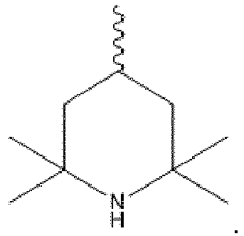
- Verfahren nach einem der Ansprüche 1 bis 3, wobei das poröse keramische Material, aus dem der Support besteht, aus der Gruppe, bestehend aus einer Silikatkeramik, einer oxidischen Keramik, einer nitridischen Keramik, einer carbidischen Keramik, einer silicidischen Keramik und Mischungen davon, ausgewählt wird.
- Verfahren nach Anspruch 4, wobei die Silikatkeramik ausgewählt wird aus Alumosilikat, Magnesiumsilikat und Mischungen davon, wie z. B. Bentonit; die oxidische Keramik ausgewählt wird aus γ-Aluminiumoxid, α-Aluminiumoxid, Titandioxid, Beryliumoxid, Zirkoniumoxid, Aluminiumtitanat, Bariumtitanat, Zinkoxid, Eisenoxiden (Ferrite) und Mischungen davon; die nitridische Keramik ausgewählt wird aus Siliciumnitrid, Bornitrid, Aluminiumnitrid und Mischungen davon; die carbidische Keramik ausgewählt wird aus Siliciumcarbid, Borcarbid, Wolframcarbid oder Mischungen davon; und die silicidische Keramik Molbydänsilicid ist.
- Verfahren nach Anspruch 4, wobei das poröse keramische Material, aus dem der Support besteht, eine carbidische Keramik ist.
- Verfahren nach Anspruch 6, wobei die carbidische Keramik ausgewählt wird aus Siliciumcarbid, Borcarbid, Wolframcarbid oder Mischungen davon.
- Verfahren nach einem der Ansprüche 1 bis 7, wobei die Menge das auf dem Support befindlichen Waschcoats ≤ 20 Gew.-% beträgt, bezogen auf die Gesamtmenge des Supports
- Verfahren nach einem der Ansprüche 1 bis 8, wobei der Support aus dem keramischen Material einen oder mehrere, vorzugsweise durchgängige Kanäle in Hauptdurchströmungsrichtung aufweist.
- Verfahren nach einem der Ansprüche 1 bis 9, wobei die Hydroformylierung bei einer Temperatur im Bereich von 65 bis 200 °C, vorzugsweise 75 bis 175 °C und besonders bevorzugt 85 bis 150 °C, durchgeführt wird.
- Verfahren nach einem der Ansprüche 1 bis 10, wobei der Druck bei der Hydroformylierung nicht größer als 35 bar, vorzugsweise nicht größer als 30 bar, besonders bevorzugt nicht größer als 25 bar ist.
Applications Claiming Priority (1)
| Application Number | Priority Date | Filing Date | Title |
|---|---|---|---|
| EP18198785 | 2018-10-05 |
Publications (1)
| Publication Number | Publication Date |
|---|---|
| EP3632885A1 true EP3632885A1 (de) | 2020-04-08 |
Family
ID=63896046
Family Applications (1)
| Application Number | Title | Priority Date | Filing Date |
|---|---|---|---|
| EP19200442.2A Pending EP3632885A1 (de) | 2018-10-05 | 2019-09-30 | Verfahren zur hydroformylierung von kurzkettigen olefinen in der gasphase |
Country Status (7)
| Country | Link |
|---|---|
| US (1) | US10654784B2 (de) |
| EP (1) | EP3632885A1 (de) |
| JP (1) | JP2020059701A (de) |
| KR (1) | KR20200039572A (de) |
| CN (1) | CN111004097B (de) |
| SG (1) | SG10201909162YA (de) |
| TW (1) | TWI819111B (de) |
Cited By (6)
| Publication number | Priority date | Publication date | Assignee | Title |
|---|---|---|---|---|
| EP4091712A1 (de) | 2021-05-18 | 2022-11-23 | Evonik Operations GmbH | Verfahren zur regenerierung eines katalysators für die hydroformylierung von olefinen in der gasphase |
| EP4234525A1 (de) | 2022-02-25 | 2023-08-30 | Evonik Operations GmbH | Verfahren zur hydrierung von aldehyden in mindestens zwei hydrierstufen |
| EP4234527A1 (de) | 2022-02-25 | 2023-08-30 | Evonik Operations GmbH | Verfahren zur hydrierung von c9-aldehyden in mindestens zwei hydrierstufen |
| EP4234528A1 (de) | 2022-02-25 | 2023-08-30 | Evonik Operations GmbH | Verfahren zur hydrierung von c13-aldehyden in mindestens zwei hydrierstufen |
| WO2024017514A1 (de) | 2022-07-19 | 2024-01-25 | Evonik Oxeno Gmbh & Co. Kg | Verfahren zur hydroformylierung von kurzkettigen olefinen in der gasphase |
| WO2024017513A1 (de) | 2022-07-19 | 2024-01-25 | Evonik Oxeno Gmbh & Co. Kg | Verfahren zur hydroformylierung von kurzkettigen olefinen in der gasphase |
Families Citing this family (7)
| Publication number | Priority date | Publication date | Assignee | Title |
|---|---|---|---|---|
| CN112888671B (zh) | 2018-10-05 | 2023-12-12 | 赢创奥克森诺有限责任两合公司 | 在气相中制备短链烯烃的方法 |
| US11008275B2 (en) | 2019-06-12 | 2021-05-18 | Evonik Operations Gmbh | Process for preparing carboxylic acids or salts thereof from hydrocarbons |
| US11440863B2 (en) | 2019-06-12 | 2022-09-13 | Evonik Operations Gmbh | Process for preparing an alcohol from hydrocarbons |
| US11365171B2 (en) | 2019-06-12 | 2022-06-21 | Evonik Operations Gmbh | Process for preparing an ester by alkoxycarbonylation |
| EP3945085B1 (de) | 2020-07-30 | 2024-01-03 | Evonik Oxeno GmbH & Co. KG | Verfahren zur herstellung von aldehyden und abtrennung des katalysatorsystems mittels membrantrennung |
| US11806669B2 (en) | 2020-12-22 | 2023-11-07 | Evonik Operations Gmbh | Variable and self-regulating permeate recycling in organophilic nanofiltration |
| EP4223737A1 (de) * | 2022-02-08 | 2023-08-09 | Evonik Operations GmbH | Optimierte thermische trennung durch vorherigen gasaustausch |
Citations (1)
| Publication number | Priority date | Publication date | Assignee | Title |
|---|---|---|---|---|
| WO2015028284A1 (de) | 2013-08-28 | 2015-03-05 | Evonik Industries Ag | Katalysator und verfahren zur hydroformylierung von ungesättigten verbindungen durch silp-katalyse |
Family Cites Families (12)
| Publication number | Priority date | Publication date | Assignee | Title |
|---|---|---|---|---|
| DE102005046250B4 (de) * | 2005-09-27 | 2020-10-08 | Evonik Operations Gmbh | Anlage zur Abtrennung von organischen Übergangsmetallkomplexkatalysatoren |
| EP2488539B2 (de) * | 2009-10-16 | 2023-12-20 | Dow Technology Investments LLC | Gasphasenhydroformulierungsverfahren |
| CN103764607A (zh) * | 2011-03-04 | 2014-04-30 | 堪萨斯大学 | 单一溶剂气体扩展的加氢甲酰化方法 |
| DE102013217386A1 (de) | 2013-09-02 | 2015-03-05 | Evonik Industries Ag | Verfahren zur Herstellung von Acrylsäure |
| DE102014201756A1 (de) | 2014-01-31 | 2015-08-06 | Evonik Degussa Gmbh | Reinigung chlorverschmutzter Organophosphorverbindungen |
| EP3059005B1 (de) | 2015-02-18 | 2018-10-24 | Evonik Degussa GmbH | Abtrennung eines homogenkatalysators aus einem reaktionsgemisch mit hilfe organophiler nanofiltration unter besonderer berücksichtigung eines membran-leistungsindikators |
| SG10201601501QA (en) | 2015-03-05 | 2016-10-28 | Evonik Degussa Gmbh | Preparation of 2,2`-biaryls in the presence of molybdenum(v) chloride |
| PL3246303T3 (pl) | 2016-05-19 | 2020-06-01 | Evonik Operations Gmbh | Wytwarzanie n-pentanalu z mieszanin surowców ubogich w buten |
| US10245578B2 (en) | 2016-11-09 | 2019-04-02 | Evonik Degussa Gmbh | Chromium- and nickel-free hydrogenation of hydroformylation mixtures |
| ZA201808002B (en) | 2017-12-01 | 2019-08-28 | Evonik Degussa Gmbh | Method for obtaining alcohols from aldehydes |
| TWI784094B (zh) | 2017-12-01 | 2022-11-21 | 德商贏創運營有限公司 | 自醛獲得醇之方法iii |
| ZA201808003B (en) | 2017-12-01 | 2019-08-28 | Evonik Degussa Gmbh | Method for obtaining alcohols from aldehydes ii |
-
2019
- 2019-09-18 US US16/574,217 patent/US10654784B2/en active Active
- 2019-09-30 EP EP19200442.2A patent/EP3632885A1/de active Pending
- 2019-10-01 SG SG10201909162YA patent/SG10201909162YA/en unknown
- 2019-10-01 KR KR1020190121325A patent/KR20200039572A/ko unknown
- 2019-10-02 JP JP2019181966A patent/JP2020059701A/ja active Pending
- 2019-10-03 TW TW108135852A patent/TWI819111B/zh active
- 2019-10-08 CN CN201910949130.2A patent/CN111004097B/zh active Active
Patent Citations (1)
| Publication number | Priority date | Publication date | Assignee | Title |
|---|---|---|---|---|
| WO2015028284A1 (de) | 2013-08-28 | 2015-03-05 | Evonik Industries Ag | Katalysator und verfahren zur hydroformylierung von ungesättigten verbindungen durch silp-katalyse |
Non-Patent Citations (3)
| Title |
|---|
| A. WEISS ET AL: "Reactor Optimization by Membrane Enhanced Operation: Process intensification with membrane reactors (ROMEO)", 10 May 2017 (2017-05-10), XP055576066, Retrieved from the Internet <URL:http://www.romeo-h2020.eu/wp-content/uploads/CBI-Symposium-Poster_AW-2.pdf> [retrieved on 20190401] * |
| ALBERTUS J. SANDEE ET AL: "ROTACAT: A Rotating Device Containing a Designed Catalyst for Highly Selective Hydroformylation", ADVANCED SYNTHESIS & CATALYSIS, vol. 343, no. 2, 26 February 2001 (2001-02-26), DE, pages 201 - 206, XP055576100, ISSN: 1615-4150, DOI: 10.1002/1615-4169(20010226)343:2<201::AID-ADSC201>3.0.CO;2-R * |
| ANONYMOUS: "Scientific publications & posters - Romeo", 1 April 2019 (2019-04-01), XP055576072, Retrieved from the Internet <URL:http://www.romeo-h2020.eu/results/scientific-publications-posters/> [retrieved on 20190401] * |
Cited By (7)
| Publication number | Priority date | Publication date | Assignee | Title |
|---|---|---|---|---|
| EP4091712A1 (de) | 2021-05-18 | 2022-11-23 | Evonik Operations GmbH | Verfahren zur regenerierung eines katalysators für die hydroformylierung von olefinen in der gasphase |
| US11951466B2 (en) | 2021-05-18 | 2024-04-09 | Evonik Oxeno Gmbh & Co. Kg | Process for regenerating a catalyst for the hydroformylation of olefins in the gas phase |
| EP4234525A1 (de) | 2022-02-25 | 2023-08-30 | Evonik Operations GmbH | Verfahren zur hydrierung von aldehyden in mindestens zwei hydrierstufen |
| EP4234527A1 (de) | 2022-02-25 | 2023-08-30 | Evonik Operations GmbH | Verfahren zur hydrierung von c9-aldehyden in mindestens zwei hydrierstufen |
| EP4234528A1 (de) | 2022-02-25 | 2023-08-30 | Evonik Operations GmbH | Verfahren zur hydrierung von c13-aldehyden in mindestens zwei hydrierstufen |
| WO2024017514A1 (de) | 2022-07-19 | 2024-01-25 | Evonik Oxeno Gmbh & Co. Kg | Verfahren zur hydroformylierung von kurzkettigen olefinen in der gasphase |
| WO2024017513A1 (de) | 2022-07-19 | 2024-01-25 | Evonik Oxeno Gmbh & Co. Kg | Verfahren zur hydroformylierung von kurzkettigen olefinen in der gasphase |
Also Published As
| Publication number | Publication date |
|---|---|
| TWI819111B (zh) | 2023-10-21 |
| US10654784B2 (en) | 2020-05-19 |
| CN111004097B (zh) | 2023-09-26 |
| SG10201909162YA (en) | 2020-05-28 |
| TW202024010A (zh) | 2020-07-01 |
| CN111004097A (zh) | 2020-04-14 |
| JP2020059701A (ja) | 2020-04-16 |
| US20200109101A1 (en) | 2020-04-09 |
| KR20200039572A (ko) | 2020-04-16 |
Similar Documents
| Publication | Publication Date | Title |
|---|---|---|
| EP3632885A1 (de) | Verfahren zur hydroformylierung von kurzkettigen olefinen in der gasphase | |
| EP3632886B1 (de) | Verfahren zur hydroformylierung von kurzkettigen olefinen unter verwendung eines heterogenisierten katalysatorsystems ohne ionische flüssigkeit | |
| EP3736258B1 (de) | Verfahren zur hydroformylierung von kurzkettigen olefinen in alkanreichen abgasströmen | |
| EP3744707B1 (de) | Verfahren zur hydroformylierung von kurzkettigen olefinen im recyclestrom einer flüssigphasen-hydroformylierung | |
| EP3038752B1 (de) | Katalysator und verfahren zur hydroformylierung von ungesättigten verbindungen durch silp-katalyse | |
| EP3632889B1 (de) | Verfahren zur hydroformylierung von c2- bis c5-olefinen ohne zwischengeschaltete stofftrennung | |
| DE102010041821A1 (de) | Einsatz von Supported Ionic Liquid Phase (SILP) Katalysatorsystemen in der Hydroformylierung von olefinhaltigen Gemischen zu Aldehydgemischen mit hohem Anteil von in 2-Stellung unverzweigten Aldehyden | |
| EP3632887B1 (de) | Verfahren zum anfahren eines hydroformylierungsreaktors | |
| EP3027298B1 (de) | Membrankaskade mit sinkender trenntemperatur | |
| WO2014056736A1 (de) | Gemisch von bisphosphiten und dessen verwendung als katalysatorgemisch in der hydroformylierung | |
| EP3632888B1 (de) | Verfahren zur in-situ herstellung eines hydroformylierungskatalysatorsystems, welches heterogenisiert auf einem support vorliegt | |
| DE102014207246A1 (de) | Immobilisierte katalytisch aktive Zusammensetzung zur Hydroformylierung von olefinhaltigen Gemischen | |
| EP3114105B1 (de) | Verfahren zur herstellung von aldehyden aus alkanen und synthesegas | |
| WO2015071266A1 (de) | Immobilisierte katalytisch aktive zusammensetzung mit tridentaten phosphorliganden in einer ionischen flüssigkeit zur hydroformylierung von olefinhaltigen gemischen | |
| WO2024017513A1 (de) | Verfahren zur hydroformylierung von kurzkettigen olefinen in der gasphase | |
| EP4091712B1 (de) | Verfahren zur regenerierung eines katalysators für die hydroformylierung von olefinen in der gasphase | |
| WO2024017514A1 (de) | Verfahren zur hydroformylierung von kurzkettigen olefinen in der gasphase | |
| EP3024838A2 (de) | Phosphoramiditderivate in der hydroformylierung von olefinhaltigen gemischen | |
| EP2985261B1 (de) | SILP-katalysierte Hydroformylierung mit CO2 |
Legal Events
| Date | Code | Title | Description |
|---|---|---|---|
| PUAI | Public reference made under article 153(3) epc to a published international application that has entered the european phase |
Free format text: ORIGINAL CODE: 0009012 |
|
| STAA | Information on the status of an ep patent application or granted ep patent |
Free format text: STATUS: REQUEST FOR EXAMINATION WAS MADE |
|
| 17P | Request for examination filed |
Effective date: 20190930 |
|
| AK | Designated contracting states |
Kind code of ref document: A1 Designated state(s): AL AT BE BG CH CY CZ DE DK EE ES FI FR GB GR HR HU IE IS IT LI LT LU LV MC MK MT NL NO PL PT RO RS SE SI SK SM TR |
|
| AX | Request for extension of the european patent |
Extension state: BA ME |
|
| STAA | Information on the status of an ep patent application or granted ep patent |
Free format text: STATUS: EXAMINATION IS IN PROGRESS |
|
| 17Q | First examination report despatched |
Effective date: 20201210 |
|
| RAP1 | Party data changed (applicant data changed or rights of an application transferred) |
Owner name: EVONIK OXENO GMBH & CO. KG |