EP3632702A1 - Pneu pour fonctionnement intensif - Google Patents
Pneu pour fonctionnement intensif Download PDFInfo
- Publication number
- EP3632702A1 EP3632702A1 EP19200011.5A EP19200011A EP3632702A1 EP 3632702 A1 EP3632702 A1 EP 3632702A1 EP 19200011 A EP19200011 A EP 19200011A EP 3632702 A1 EP3632702 A1 EP 3632702A1
- Authority
- EP
- European Patent Office
- Prior art keywords
- tire
- shoulder
- mass
- axial direction
- tire axial
- Prior art date
- Legal status (The legal status is an assumption and is not a legal conclusion. Google has not performed a legal analysis and makes no representation as to the accuracy of the status listed.)
- Granted
Links
- 229920001971 elastomer Polymers 0.000 claims abstract description 81
- 239000005060 rubber Substances 0.000 claims abstract description 81
- 239000006229 carbon black Substances 0.000 claims abstract description 51
- RRHGJUQNOFWUDK-UHFFFAOYSA-N Isoprene Chemical compound CC(=C)C=C RRHGJUQNOFWUDK-UHFFFAOYSA-N 0.000 claims abstract description 29
- LZZYPRNAOMGNLH-UHFFFAOYSA-M Cetrimonium bromide Chemical compound [Br-].CCCCCCCCCCCCCCCC[N+](C)(C)C LZZYPRNAOMGNLH-UHFFFAOYSA-M 0.000 claims abstract description 25
- 239000002245 particle Substances 0.000 claims abstract description 13
- 238000001179 sorption measurement Methods 0.000 claims abstract description 12
- 239000000203 mixture Substances 0.000 claims description 41
- 235000019241 carbon black Nutrition 0.000 description 48
- 229920005989 resin Polymers 0.000 description 44
- 239000011347 resin Substances 0.000 description 44
- VYPSYNLAJGMNEJ-UHFFFAOYSA-N Silicium dioxide Chemical compound O=[Si]=O VYPSYNLAJGMNEJ-UHFFFAOYSA-N 0.000 description 43
- 229920003048 styrene butadiene rubber Polymers 0.000 description 26
- 239000007788 liquid Substances 0.000 description 22
- 238000004073 vulcanization Methods 0.000 description 22
- 239000000377 silicon dioxide Substances 0.000 description 21
- -1 diglycidylamino compounds Chemical class 0.000 description 20
- 239000006087 Silane Coupling Agent Substances 0.000 description 19
- 239000005062 Polybutadiene Substances 0.000 description 18
- PPBRXRYQALVLMV-UHFFFAOYSA-N Styrene Chemical compound C=CC1=CC=CC=C1 PPBRXRYQALVLMV-UHFFFAOYSA-N 0.000 description 18
- 229920002857 polybutadiene Polymers 0.000 description 18
- 239000000126 substance Substances 0.000 description 18
- 239000002174 Styrene-butadiene Substances 0.000 description 17
- RSWGJHLUYNHPMX-UHFFFAOYSA-N Abietic-Saeure Natural products C12CCC(C(C)C)=CC2=CCC2C1(C)CCCC2(C)C(O)=O RSWGJHLUYNHPMX-UHFFFAOYSA-N 0.000 description 16
- KHPCPRHQVVSZAH-HUOMCSJISA-N Rosin Natural products O(C/C=C/c1ccccc1)[C@H]1[C@H](O)[C@@H](O)[C@@H](O)[C@@H](CO)O1 KHPCPRHQVVSZAH-HUOMCSJISA-N 0.000 description 16
- KHPCPRHQVVSZAH-UHFFFAOYSA-N trans-cinnamyl beta-D-glucopyranoside Natural products OC1C(O)C(O)C(CO)OC1OCC=CC1=CC=CC=C1 KHPCPRHQVVSZAH-UHFFFAOYSA-N 0.000 description 16
- 235000007586 terpenes Nutrition 0.000 description 15
- 239000003963 antioxidant agent Substances 0.000 description 14
- 235000001508 sulfur Nutrition 0.000 description 14
- NINIDFKCEFEMDL-UHFFFAOYSA-N Sulfur Chemical compound [S] NINIDFKCEFEMDL-UHFFFAOYSA-N 0.000 description 13
- 125000000524 functional group Chemical group 0.000 description 12
- 229920000642 polymer Polymers 0.000 description 12
- 229910052717 sulfur Inorganic materials 0.000 description 12
- 239000011593 sulfur Substances 0.000 description 12
- 150000001875 compounds Chemical class 0.000 description 11
- DOIRQSBPFJWKBE-UHFFFAOYSA-N dibutyl phthalate Chemical compound CCCCOC(=O)C1=CC=CC=C1C(=O)OCCCC DOIRQSBPFJWKBE-UHFFFAOYSA-N 0.000 description 11
- YBYIRNPNPLQARY-UHFFFAOYSA-N 1H-indene Chemical compound C1=CC=C2CC=CC2=C1 YBYIRNPNPLQARY-UHFFFAOYSA-N 0.000 description 10
- XLOMVQKBTHCTTD-UHFFFAOYSA-N Zinc monoxide Chemical compound [Zn]=O XLOMVQKBTHCTTD-UHFFFAOYSA-N 0.000 description 10
- 238000004898 kneading Methods 0.000 description 10
- 244000043261 Hevea brasiliensis Species 0.000 description 9
- 125000003277 amino group Chemical group 0.000 description 9
- 229920003052 natural elastomer Polymers 0.000 description 9
- 229920001194 natural rubber Polymers 0.000 description 9
- 239000001993 wax Substances 0.000 description 9
- GRWFGVWFFZKLTI-IUCAKERBSA-N (-)-α-pinene Chemical compound CC1=CC[C@@H]2C(C)(C)[C@H]1C2 GRWFGVWFFZKLTI-IUCAKERBSA-N 0.000 description 8
- XMGQYMWWDOXHJM-UHFFFAOYSA-N limonene Chemical compound CC(=C)C1CCC(C)=CC1 XMGQYMWWDOXHJM-UHFFFAOYSA-N 0.000 description 8
- 238000004519 manufacturing process Methods 0.000 description 8
- 238000002156 mixing Methods 0.000 description 8
- ISWSIDIOOBJBQZ-UHFFFAOYSA-N phenol group Chemical group C1(=CC=CC=C1)O ISWSIDIOOBJBQZ-UHFFFAOYSA-N 0.000 description 7
- BGNGWHSBYQYVRX-UHFFFAOYSA-N 4-(dimethylamino)benzaldehyde Chemical compound CN(C)C1=CC=C(C=O)C=C1 BGNGWHSBYQYVRX-UHFFFAOYSA-N 0.000 description 6
- 239000002253 acid Substances 0.000 description 6
- XYLMUPLGERFSHI-UHFFFAOYSA-N alpha-Methylstyrene Chemical compound CC(=C)C1=CC=CC=C1 XYLMUPLGERFSHI-UHFFFAOYSA-N 0.000 description 6
- 125000003118 aryl group Chemical group 0.000 description 6
- 239000003795 chemical substances by application Substances 0.000 description 6
- DMBHHRLKUKUOEG-UHFFFAOYSA-N diphenylamine Chemical compound C=1C=CC=CC=1NC1=CC=CC=C1 DMBHHRLKUKUOEG-UHFFFAOYSA-N 0.000 description 6
- 239000003921 oil Substances 0.000 description 6
- 150000003505 terpenes Chemical class 0.000 description 6
- 238000012360 testing method Methods 0.000 description 6
- 235000014692 zinc oxide Nutrition 0.000 description 6
- ZCYVEMRRCGMTRW-UHFFFAOYSA-N 7553-56-2 Chemical compound [I] ZCYVEMRRCGMTRW-UHFFFAOYSA-N 0.000 description 5
- 235000021355 Stearic acid Nutrition 0.000 description 5
- 230000003078 antioxidant effect Effects 0.000 description 5
- 230000000052 comparative effect Effects 0.000 description 5
- 150000001993 dienes Chemical class 0.000 description 5
- 125000003700 epoxy group Chemical group 0.000 description 5
- 229910052740 iodine Inorganic materials 0.000 description 5
- 239000011630 iodine Substances 0.000 description 5
- 229920003049 isoprene rubber Polymers 0.000 description 5
- 238000000034 method Methods 0.000 description 5
- QIQXTHQIDYTFRH-UHFFFAOYSA-N octadecanoic acid Chemical compound CCCCCCCCCCCCCCCCCC(O)=O QIQXTHQIDYTFRH-UHFFFAOYSA-N 0.000 description 5
- 239000011787 zinc oxide Substances 0.000 description 5
- WTARULDDTDQWMU-RKDXNWHRSA-N (+)-β-pinene Chemical compound C1[C@H]2C(C)(C)[C@@H]1CCC2=C WTARULDDTDQWMU-RKDXNWHRSA-N 0.000 description 4
- WTARULDDTDQWMU-IUCAKERBSA-N (-)-Nopinene Natural products C1[C@@H]2C(C)(C)[C@H]1CCC2=C WTARULDDTDQWMU-IUCAKERBSA-N 0.000 description 4
- IANQTJSKSUMEQM-UHFFFAOYSA-N 1-benzofuran Chemical compound C1=CC=C2OC=CC2=C1 IANQTJSKSUMEQM-UHFFFAOYSA-N 0.000 description 4
- ZZMVLMVFYMGSMY-UHFFFAOYSA-N 4-n-(4-methylpentan-2-yl)-1-n-phenylbenzene-1,4-diamine Chemical compound C1=CC(NC(C)CC(C)C)=CC=C1NC1=CC=CC=C1 ZZMVLMVFYMGSMY-UHFFFAOYSA-N 0.000 description 4
- IJGRMHOSHXDMSA-UHFFFAOYSA-N Atomic nitrogen Chemical compound N#N IJGRMHOSHXDMSA-UHFFFAOYSA-N 0.000 description 4
- OKTJSMMVPCPJKN-UHFFFAOYSA-N Carbon Chemical compound [C] OKTJSMMVPCPJKN-UHFFFAOYSA-N 0.000 description 4
- ZRALSGWEFCBTJO-UHFFFAOYSA-N Guanidine Chemical compound NC(N)=N ZRALSGWEFCBTJO-UHFFFAOYSA-N 0.000 description 4
- 229920000459 Nitrile rubber Polymers 0.000 description 4
- WTARULDDTDQWMU-UHFFFAOYSA-N Pseudopinene Natural products C1C2C(C)(C)C1CCC2=C WTARULDDTDQWMU-UHFFFAOYSA-N 0.000 description 4
- XCPQUQHBVVXMRQ-UHFFFAOYSA-N alpha-Fenchene Natural products C1CC2C(=C)CC1C2(C)C XCPQUQHBVVXMRQ-UHFFFAOYSA-N 0.000 description 4
- MVNCAPSFBDBCGF-UHFFFAOYSA-N alpha-pinene Natural products CC1=CCC23C1CC2C3(C)C MVNCAPSFBDBCGF-UHFFFAOYSA-N 0.000 description 4
- 229930006722 beta-pinene Natural products 0.000 description 4
- IISBACLAFKSPIT-UHFFFAOYSA-N bisphenol A Chemical compound C=1C=C(O)C=CC=1C(C)(C)C1=CC=C(O)C=C1 IISBACLAFKSPIT-UHFFFAOYSA-N 0.000 description 4
- 229920001577 copolymer Polymers 0.000 description 4
- 230000000694 effects Effects 0.000 description 4
- LCWMKIHBLJLORW-UHFFFAOYSA-N gamma-carene Natural products C1CC(=C)CC2C(C)(C)C21 LCWMKIHBLJLORW-UHFFFAOYSA-N 0.000 description 4
- 238000005227 gel permeation chromatography Methods 0.000 description 4
- 239000003607 modifier Substances 0.000 description 4
- 229910052757 nitrogen Inorganic materials 0.000 description 4
- OQCDKBAXFALNLD-UHFFFAOYSA-N octadecanoic acid Natural products CCCCCCCC(C)CCCCCCCCC(O)=O OQCDKBAXFALNLD-UHFFFAOYSA-N 0.000 description 4
- 230000000379 polymerizing effect Effects 0.000 description 4
- GRWFGVWFFZKLTI-UHFFFAOYSA-N rac-alpha-Pinene Natural products CC1=CCC2C(C)(C)C1C2 GRWFGVWFFZKLTI-UHFFFAOYSA-N 0.000 description 4
- 239000008117 stearic acid Substances 0.000 description 4
- KPAPHODVWOVUJL-UHFFFAOYSA-N 1-benzofuran;1h-indene Chemical compound C1=CC=C2CC=CC2=C1.C1=CC=C2OC=CC2=C1 KPAPHODVWOVUJL-UHFFFAOYSA-N 0.000 description 3
- 230000002378 acidificating effect Effects 0.000 description 3
- 239000000654 additive Substances 0.000 description 3
- 125000003545 alkoxy group Chemical group 0.000 description 3
- 125000005370 alkoxysilyl group Chemical group 0.000 description 3
- 125000004432 carbon atom Chemical group C* 0.000 description 3
- 125000003178 carboxy group Chemical group [H]OC(*)=O 0.000 description 3
- 238000002485 combustion reaction Methods 0.000 description 3
- 239000000945 filler Substances 0.000 description 3
- 229940087305 limonene Drugs 0.000 description 3
- 239000000178 monomer Substances 0.000 description 3
- IUJLOAKJZQBENM-UHFFFAOYSA-N n-(1,3-benzothiazol-2-ylsulfanyl)-2-methylpropan-2-amine Chemical compound C1=CC=C2SC(SNC(C)(C)C)=NC2=C1 IUJLOAKJZQBENM-UHFFFAOYSA-N 0.000 description 3
- 150000003097 polyterpenes Chemical class 0.000 description 3
- 239000002994 raw material Substances 0.000 description 3
- KUAZQDVKQLNFPE-UHFFFAOYSA-N thiram Chemical compound CN(C)C(=S)SSC(=S)N(C)C KUAZQDVKQLNFPE-UHFFFAOYSA-N 0.000 description 3
- 229960002447 thiram Drugs 0.000 description 3
- 239000003981 vehicle Substances 0.000 description 3
- 229920002554 vinyl polymer Polymers 0.000 description 3
- 239000004636 vulcanized rubber Substances 0.000 description 3
- JSNRRGGBADWTMC-UHFFFAOYSA-N (6E)-7,11-dimethyl-3-methylene-1,6,10-dodecatriene Chemical compound CC(C)=CCCC(C)=CCCC(=C)C=C JSNRRGGBADWTMC-UHFFFAOYSA-N 0.000 description 2
- YXIWHUQXZSMYRE-UHFFFAOYSA-N 1,3-benzothiazole-2-thiol Chemical compound C1=CC=C2SC(S)=NC2=C1 YXIWHUQXZSMYRE-UHFFFAOYSA-N 0.000 description 2
- CBCKQZAAMUWICA-UHFFFAOYSA-N 1,4-phenylenediamine Chemical compound NC1=CC=C(N)C=C1 CBCKQZAAMUWICA-UHFFFAOYSA-N 0.000 description 2
- ZNRLMGFXSPUZNR-UHFFFAOYSA-N 2,2,4-trimethyl-1h-quinoline Chemical compound C1=CC=C2C(C)=CC(C)(C)NC2=C1 ZNRLMGFXSPUZNR-UHFFFAOYSA-N 0.000 description 2
- VVBLNCFGVYUYGU-UHFFFAOYSA-N 4,4'-Bis(dimethylamino)benzophenone Chemical compound C1=CC(N(C)C)=CC=C1C(=O)C1=CC=C(N(C)C)C=C1 VVBLNCFGVYUYGU-UHFFFAOYSA-N 0.000 description 2
- PAYRUJLWNCNPSJ-UHFFFAOYSA-N Aniline Chemical compound NC1=CC=CC=C1 PAYRUJLWNCNPSJ-UHFFFAOYSA-N 0.000 description 2
- VTYYLEPIZMXCLO-UHFFFAOYSA-L Calcium carbonate Chemical compound [Ca+2].[O-]C([O-])=O VTYYLEPIZMXCLO-UHFFFAOYSA-L 0.000 description 2
- 239000004215 Carbon black (E152) Substances 0.000 description 2
- 229920002943 EPDM rubber Polymers 0.000 description 2
- WEEGYLXZBRQIMU-UHFFFAOYSA-N Eucalyptol Chemical compound C1CC2CCC1(C)OC2(C)C WEEGYLXZBRQIMU-UHFFFAOYSA-N 0.000 description 2
- SECXISVLQFMRJM-UHFFFAOYSA-N N-Methylpyrrolidone Chemical compound CN1CCCC1=O SECXISVLQFMRJM-UHFFFAOYSA-N 0.000 description 2
- CHJJGSNFBQVOTG-UHFFFAOYSA-N N-methyl-guanidine Natural products CNC(N)=N CHJJGSNFBQVOTG-UHFFFAOYSA-N 0.000 description 2
- 239000004793 Polystyrene Substances 0.000 description 2
- SMWDFEZZVXVKRB-UHFFFAOYSA-N Quinoline Chemical compound N1=CC=CC2=CC=CC=C21 SMWDFEZZVXVKRB-UHFFFAOYSA-N 0.000 description 2
- 229920005683 SIBR Polymers 0.000 description 2
- UCKMPCXJQFINFW-UHFFFAOYSA-N Sulphide Chemical compound [S-2] UCKMPCXJQFINFW-UHFFFAOYSA-N 0.000 description 2
- MOYAFQVGZZPNRA-UHFFFAOYSA-N Terpinolene Chemical compound CC(C)=C1CCC(C)=CC1 MOYAFQVGZZPNRA-UHFFFAOYSA-N 0.000 description 2
- 125000003368 amide group Chemical group 0.000 description 2
- 150000001491 aromatic compounds Chemical class 0.000 description 2
- UAHWPYUMFXYFJY-UHFFFAOYSA-N beta-myrcene Chemical compound CC(C)=CCCC(=C)C=C UAHWPYUMFXYFJY-UHFFFAOYSA-N 0.000 description 2
- VTEKOFXDMRILGB-UHFFFAOYSA-N bis(2-ethylhexyl)carbamothioylsulfanyl n,n-bis(2-ethylhexyl)carbamodithioate Chemical compound CCCCC(CC)CN(CC(CC)CCCC)C(=S)SSC(=S)N(CC(CC)CCCC)CC(CC)CCCC VTEKOFXDMRILGB-UHFFFAOYSA-N 0.000 description 2
- 238000006243 chemical reaction Methods 0.000 description 2
- 239000004927 clay Substances 0.000 description 2
- 229910052570 clay Inorganic materials 0.000 description 2
- 238000011161 development Methods 0.000 description 2
- AFZSMODLJJCVPP-UHFFFAOYSA-N dibenzothiazol-2-yl disulfide Chemical compound C1=CC=C2SC(SSC=3SC4=CC=CC=C4N=3)=NC2=C1 AFZSMODLJJCVPP-UHFFFAOYSA-N 0.000 description 2
- WITDFSFZHZYQHB-UHFFFAOYSA-N dibenzylcarbamothioylsulfanyl n,n-dibenzylcarbamodithioate Chemical compound C=1C=CC=CC=1CN(CC=1C=CC=CC=1)C(=S)SSC(=S)N(CC=1C=CC=CC=1)CC1=CC=CC=C1 WITDFSFZHZYQHB-UHFFFAOYSA-N 0.000 description 2
- 235000014113 dietary fatty acids Nutrition 0.000 description 2
- SWSQBOPZIKWTGO-UHFFFAOYSA-N dimethylaminoamidine Natural products CN(C)C(N)=N SWSQBOPZIKWTGO-UHFFFAOYSA-N 0.000 description 2
- 150000002148 esters Chemical class 0.000 description 2
- 150000002170 ethers Chemical class 0.000 description 2
- 239000000194 fatty acid Substances 0.000 description 2
- 229930195729 fatty acid Natural products 0.000 description 2
- 150000004665 fatty acids Chemical class 0.000 description 2
- NNRLDGQZIVUQTE-UHFFFAOYSA-N gamma-Terpineol Chemical compound CC(C)=C1CCC(C)(O)CC1 NNRLDGQZIVUQTE-UHFFFAOYSA-N 0.000 description 2
- 238000007429 general method Methods 0.000 description 2
- 229920001519 homopolymer Polymers 0.000 description 2
- 229930195733 hydrocarbon Natural products 0.000 description 2
- 150000002430 hydrocarbons Chemical class 0.000 description 2
- 125000002887 hydroxy group Chemical group [H]O* 0.000 description 2
- 230000006872 improvement Effects 0.000 description 2
- 230000003993 interaction Effects 0.000 description 2
- 235000001510 limonene Nutrition 0.000 description 2
- VNWKTOKETHGBQD-UHFFFAOYSA-N methane Chemical compound C VNWKTOKETHGBQD-UHFFFAOYSA-N 0.000 description 2
- DEQZTKGFXNUBJL-UHFFFAOYSA-N n-(1,3-benzothiazol-2-ylsulfanyl)cyclohexanamine Chemical compound C1CCCCC1NSC1=NC2=CC=CC=C2S1 DEQZTKGFXNUBJL-UHFFFAOYSA-N 0.000 description 2
- 239000012188 paraffin wax Substances 0.000 description 2
- 239000012169 petroleum derived wax Substances 0.000 description 2
- 235000019381 petroleum wax Nutrition 0.000 description 2
- 229920001084 poly(chloroprene) Polymers 0.000 description 2
- 238000006116 polymerization reaction Methods 0.000 description 2
- 229920002223 polystyrene Polymers 0.000 description 2
- 229920000346 polystyrene-polyisoprene block-polystyrene Polymers 0.000 description 2
- 239000010734 process oil Substances 0.000 description 2
- 239000012763 reinforcing filler Substances 0.000 description 2
- 150000004756 silanes Chemical class 0.000 description 2
- 229920000468 styrene butadiene styrene block copolymer Polymers 0.000 description 2
- TXDNPSYEJHXKMK-UHFFFAOYSA-N sulfanylsilane Chemical compound S[SiH3] TXDNPSYEJHXKMK-UHFFFAOYSA-N 0.000 description 2
- QAZLUNIWYYOJPC-UHFFFAOYSA-M sulfenamide Chemical compound [Cl-].COC1=C(C)C=[N+]2C3=NC4=CC=C(OC)C=C4N3SCC2=C1C QAZLUNIWYYOJPC-UHFFFAOYSA-M 0.000 description 2
- 238000010059 sulfur vulcanization Methods 0.000 description 2
- 239000000454 talc Substances 0.000 description 2
- 229910052623 talc Inorganic materials 0.000 description 2
- 125000000101 thioether group Chemical group 0.000 description 2
- 238000013519 translation Methods 0.000 description 2
- VTHOKNTVYKTUPI-UHFFFAOYSA-N triethoxy-[3-(3-triethoxysilylpropyltetrasulfanyl)propyl]silane Chemical compound CCO[Si](OCC)(OCC)CCCSSSSCCC[Si](OCC)(OCC)OCC VTHOKNTVYKTUPI-UHFFFAOYSA-N 0.000 description 2
- XLYOFNOQVPJJNP-UHFFFAOYSA-N water Substances O XLYOFNOQVPJJNP-UHFFFAOYSA-N 0.000 description 2
- OGLDWXZKYODSOB-UHFFFAOYSA-N α-phellandrene Chemical compound CC(C)C1CC=C(C)C=C1 OGLDWXZKYODSOB-UHFFFAOYSA-N 0.000 description 2
- YHQGMYUVUMAZJR-UHFFFAOYSA-N α-terpinene Chemical compound CC(C)C1=CC=C(C)CC1 YHQGMYUVUMAZJR-UHFFFAOYSA-N 0.000 description 2
- YKFLAYDHMOASIY-UHFFFAOYSA-N γ-terpinene Chemical compound CC(C)C1=CCC(C)=CC1 YKFLAYDHMOASIY-UHFFFAOYSA-N 0.000 description 2
- WYTZZXDRDKSJID-UHFFFAOYSA-N (3-aminopropyl)triethoxysilane Chemical compound CCO[Si](OCC)(OCC)CCCN WYTZZXDRDKSJID-UHFFFAOYSA-N 0.000 description 1
- CXENHBSYCFFKJS-UHFFFAOYSA-N (3E,6E)-3,7,11-Trimethyl-1,3,6,10-dodecatetraene Natural products CC(C)=CCCC(C)=CCC=C(C)C=C CXENHBSYCFFKJS-UHFFFAOYSA-N 0.000 description 1
- GQVMHMFBVWSSPF-SOYUKNQTSA-N (4E,6E)-2,6-dimethylocta-2,4,6-triene Chemical compound C\C=C(/C)\C=C\C=C(C)C GQVMHMFBVWSSPF-SOYUKNQTSA-N 0.000 description 1
- WUOACPNHFRMFPN-SECBINFHSA-N (S)-(-)-alpha-terpineol Chemical compound CC1=CC[C@@H](C(C)(C)O)CC1 WUOACPNHFRMFPN-SECBINFHSA-N 0.000 description 1
- RUJPNZNXGCHGID-UHFFFAOYSA-N (Z)-beta-Terpineol Natural products CC(=C)C1CCC(C)(O)CC1 RUJPNZNXGCHGID-UHFFFAOYSA-N 0.000 description 1
- TUMNHQRORINJKE-UHFFFAOYSA-N 1,1-diethylurea Chemical compound CCN(CC)C(N)=O TUMNHQRORINJKE-UHFFFAOYSA-N 0.000 description 1
- OPNUROKCUBTKLF-UHFFFAOYSA-N 1,2-bis(2-methylphenyl)guanidine Chemical compound CC1=CC=CC=C1N\C(N)=N\C1=CC=CC=C1C OPNUROKCUBTKLF-UHFFFAOYSA-N 0.000 description 1
- OUPZKGBUJRBPGC-UHFFFAOYSA-N 1,3,5-tris(oxiran-2-ylmethyl)-1,3,5-triazinane-2,4,6-trione Chemical class O=C1N(CC2OC2)C(=O)N(CC2OC2)C(=O)N1CC1CO1 OUPZKGBUJRBPGC-UHFFFAOYSA-N 0.000 description 1
- CYSGHNMQYZDMIA-UHFFFAOYSA-N 1,3-Dimethyl-2-imidazolidinon Chemical compound CN1CCN(C)C1=O CYSGHNMQYZDMIA-UHFFFAOYSA-N 0.000 description 1
- QUQZYDAVOUBILO-UHFFFAOYSA-N 1,3-bis(n-phenylanilino)propan-2-one Chemical compound C=1C=CC=CC=1N(C=1C=CC=CC=1)CC(=O)CN(C=1C=CC=CC=1)C1=CC=CC=C1 QUQZYDAVOUBILO-UHFFFAOYSA-N 0.000 description 1
- NYCCIHSMVNRABA-UHFFFAOYSA-N 1,3-diethylimidazolidin-2-one Chemical compound CCN1CCN(CC)C1=O NYCCIHSMVNRABA-UHFFFAOYSA-N 0.000 description 1
- OWRCNXZUPFZXOS-UHFFFAOYSA-N 1,3-diphenylguanidine Chemical compound C=1C=CC=CC=1NC(=N)NC1=CC=CC=C1 OWRCNXZUPFZXOS-UHFFFAOYSA-N 0.000 description 1
- RFFOTVCVTJUTAD-AOOOYVTPSA-N 1,4-cineole Chemical compound CC(C)[C@]12CC[C@](C)(CC1)O2 RFFOTVCVTJUTAD-AOOOYVTPSA-N 0.000 description 1
- FILVIKOEJGORQS-UHFFFAOYSA-N 1,5-dimethylpyrrolidin-2-one Chemical compound CC1CCC(=O)N1C FILVIKOEJGORQS-UHFFFAOYSA-N 0.000 description 1
- GGFFPCJSGABICG-UHFFFAOYSA-N 1,7-bis[ethyl(methyl)amino]heptan-4-one Chemical compound CCN(C)CCCC(=O)CCCN(C)CC GGFFPCJSGABICG-UHFFFAOYSA-N 0.000 description 1
- UWFRVQVNYNPBEF-UHFFFAOYSA-N 1-(2,4-dimethylphenyl)propan-1-one Chemical compound CCC(=O)C1=CC=C(C)C=C1C UWFRVQVNYNPBEF-UHFFFAOYSA-N 0.000 description 1
- HUDYANRNMZDQGA-UHFFFAOYSA-N 1-[4-(dimethylamino)phenyl]ethanone Chemical compound CN(C)C1=CC=C(C(C)=O)C=C1 HUDYANRNMZDQGA-UHFFFAOYSA-N 0.000 description 1
- YEUIMZOJSJEGFM-UHFFFAOYSA-N 1-cyclohexyl-n,n-bis(oxiran-2-ylmethyl)methanamine Chemical compound C1OC1CN(CC1CCCCC1)CC1CO1 YEUIMZOJSJEGFM-UHFFFAOYSA-N 0.000 description 1
- PBGPBHYPCGDFEZ-UHFFFAOYSA-N 1-ethenylpiperidin-2-one Chemical compound C=CN1CCCCC1=O PBGPBHYPCGDFEZ-UHFFFAOYSA-N 0.000 description 1
- UZXXRFKXXJEKJA-UHFFFAOYSA-N 1-ethyl-3-methylimidazolidin-2-one Chemical compound CCN1CCN(C)C1=O UZXXRFKXXJEKJA-UHFFFAOYSA-N 0.000 description 1
- LRTOHSLOFCWHRF-UHFFFAOYSA-N 1-methyl-1h-indene Chemical compound C1=CC=C2C(C)C=CC2=C1 LRTOHSLOFCWHRF-UHFFFAOYSA-N 0.000 description 1
- QOEUNLQGZBSTBB-UHFFFAOYSA-N 1-methylazetidin-2-one Chemical compound CN1CCC1=O QOEUNLQGZBSTBB-UHFFFAOYSA-N 0.000 description 1
- GGYVTHJIUNGKFZ-UHFFFAOYSA-N 1-methylpiperidin-2-one Chemical compound CN1CCCCC1=O GGYVTHJIUNGKFZ-UHFFFAOYSA-N 0.000 description 1
- VETPHHXZEJAYOB-UHFFFAOYSA-N 1-n,4-n-dinaphthalen-2-ylbenzene-1,4-diamine Chemical compound C1=CC=CC2=CC(NC=3C=CC(NC=4C=C5C=CC=CC5=CC=4)=CC=3)=CC=C21 VETPHHXZEJAYOB-UHFFFAOYSA-N 0.000 description 1
- RUFPHBVGCFYCNW-UHFFFAOYSA-N 1-naphthylamine Chemical compound C1=CC=C2C(N)=CC=CC2=C1 RUFPHBVGCFYCNW-UHFFFAOYSA-N 0.000 description 1
- PPBBOELSIAPOOU-UHFFFAOYSA-N 1-phenylazepan-2-one Chemical compound O=C1CCCCCN1C1=CC=CC=C1 PPBBOELSIAPOOU-UHFFFAOYSA-N 0.000 description 1
- OPISVEPYALEQJT-UHFFFAOYSA-N 1-phenylazetidin-2-one Chemical compound O=C1CCN1C1=CC=CC=C1 OPISVEPYALEQJT-UHFFFAOYSA-N 0.000 description 1
- NKOGCJIYHZVBDR-UHFFFAOYSA-N 1-phenylpiperidin-2-one Chemical compound O=C1CCCCN1C1=CC=CC=C1 NKOGCJIYHZVBDR-UHFFFAOYSA-N 0.000 description 1
- JMVIVASFFKKFQK-UHFFFAOYSA-N 1-phenylpyrrolidin-2-one Chemical compound O=C1CCCN1C1=CC=CC=C1 JMVIVASFFKKFQK-UHFFFAOYSA-N 0.000 description 1
- LUVQSCCABURXJL-UHFFFAOYSA-N 1-tert-butylpyrrolidin-2-one Chemical compound CC(C)(C)N1CCCC1=O LUVQSCCABURXJL-UHFFFAOYSA-N 0.000 description 1
- WHRZCXAVMTUTDD-UHFFFAOYSA-N 1h-furo[2,3-d]pyrimidin-2-one Chemical compound N1C(=O)N=C2OC=CC2=C1 WHRZCXAVMTUTDD-UHFFFAOYSA-N 0.000 description 1
- BYLSIPUARIZAHZ-UHFFFAOYSA-N 2,4,6-tris(1-phenylethyl)phenol Chemical compound C=1C(C(C)C=2C=CC=CC=2)=C(O)C(C(C)C=2C=CC=CC=2)=CC=1C(C)C1=CC=CC=C1 BYLSIPUARIZAHZ-UHFFFAOYSA-N 0.000 description 1
- OVSKIKFHRZPJSS-UHFFFAOYSA-N 2,4-D Chemical compound OC(=O)COC1=CC=C(Cl)C=C1Cl OVSKIKFHRZPJSS-UHFFFAOYSA-N 0.000 description 1
- HIXDQWDOVZUNNA-UHFFFAOYSA-N 2-(3,4-dimethoxyphenyl)-5-hydroxy-7-methoxychromen-4-one Chemical compound C=1C(OC)=CC(O)=C(C(C=2)=O)C=1OC=2C1=CC=C(OC)C(OC)=C1 HIXDQWDOVZUNNA-UHFFFAOYSA-N 0.000 description 1
- OZDGMOYKSFPLSE-UHFFFAOYSA-N 2-Methylaziridine Chemical compound CC1CN1 OZDGMOYKSFPLSE-UHFFFAOYSA-N 0.000 description 1
- SYEWHONLFGZGLK-UHFFFAOYSA-N 2-[1,3-bis(oxiran-2-ylmethoxy)propan-2-yloxymethyl]oxirane Chemical compound C1OC1COCC(OCC1OC1)COCC1CO1 SYEWHONLFGZGLK-UHFFFAOYSA-N 0.000 description 1
- NUPIVHLUIBBDPK-UHFFFAOYSA-N 2-[[3,5-bis(oxiran-2-ylmethyl)phenyl]methyl]oxirane Chemical compound C=1C(CC2OC2)=CC(CC2OC2)=CC=1CC1CO1 NUPIVHLUIBBDPK-UHFFFAOYSA-N 0.000 description 1
- PFJPHQUZCRACDD-UHFFFAOYSA-N 2-[[4-(oxiran-2-ylmethyl)phenyl]methyl]oxirane Chemical compound C=1C=C(CC2OC2)C=CC=1CC1CO1 PFJPHQUZCRACDD-UHFFFAOYSA-N 0.000 description 1
- OVEUFHOBGCSKSH-UHFFFAOYSA-N 2-methyl-n,n-bis(oxiran-2-ylmethyl)aniline Chemical compound CC1=CC=CC=C1N(CC1OC1)CC1OC1 OVEUFHOBGCSKSH-UHFFFAOYSA-N 0.000 description 1
- QTWJRLJHJPIABL-UHFFFAOYSA-N 2-methylphenol;3-methylphenol;4-methylphenol Chemical compound CC1=CC=C(O)C=C1.CC1=CC=CC(O)=C1.CC1=CC=CC=C1O QTWJRLJHJPIABL-UHFFFAOYSA-N 0.000 description 1
- CBDWNRVMCWOYEK-UHFFFAOYSA-N 2-triethoxysilyl-n,n-bis(trimethylsilyl)ethanamine Chemical compound CCO[Si](OCC)(OCC)CCN([Si](C)(C)C)[Si](C)(C)C CBDWNRVMCWOYEK-UHFFFAOYSA-N 0.000 description 1
- DVNPFNZTPMWRAX-UHFFFAOYSA-N 2-triethoxysilylethanethiol Chemical compound CCO[Si](CCS)(OCC)OCC DVNPFNZTPMWRAX-UHFFFAOYSA-N 0.000 description 1
- RHAYEZASBOVCGH-UHFFFAOYSA-N 2-trimethoxysilyl-n,n-bis(trimethylsilyl)ethanamine Chemical compound CO[Si](OC)(OC)CCN([Si](C)(C)C)[Si](C)(C)C RHAYEZASBOVCGH-UHFFFAOYSA-N 0.000 description 1
- KSCAZPYHLGGNPZ-UHFFFAOYSA-N 3-chloropropyl(triethoxy)silane Chemical compound CCO[Si](OCC)(OCC)CCCCl KSCAZPYHLGGNPZ-UHFFFAOYSA-N 0.000 description 1
- OXYZDRAJMHGSMW-UHFFFAOYSA-N 3-chloropropyl(trimethoxy)silane Chemical compound CO[Si](OC)(OC)CCCCl OXYZDRAJMHGSMW-UHFFFAOYSA-N 0.000 description 1
- MECNWXGGNCJFQJ-UHFFFAOYSA-N 3-piperidin-1-ylpropane-1,2-diol Chemical compound OCC(O)CN1CCCCC1 MECNWXGGNCJFQJ-UHFFFAOYSA-N 0.000 description 1
- SLSKAIZCBJQHFI-UHFFFAOYSA-N 3-triethoxysilyl-n,n-bis(trimethylsilyl)propan-1-amine Chemical compound CCO[Si](OCC)(OCC)CCCN([Si](C)(C)C)[Si](C)(C)C SLSKAIZCBJQHFI-UHFFFAOYSA-N 0.000 description 1
- ZSFMFCWJHYPFPG-UHFFFAOYSA-N 3-triethoxysilylpropyl 2-methylthiirane-2-carboxylate Chemical compound CCO[Si](OCC)(OCC)CCCOC(=O)C1(C)CS1 ZSFMFCWJHYPFPG-UHFFFAOYSA-N 0.000 description 1
- JOGZENPUTBJZBI-UHFFFAOYSA-N 3-trimethoxysilyl-n,n-bis(trimethylsilyl)propan-1-amine Chemical compound CO[Si](OC)(OC)CCCN([Si](C)(C)C)[Si](C)(C)C JOGZENPUTBJZBI-UHFFFAOYSA-N 0.000 description 1
- SJECZPVISLOESU-UHFFFAOYSA-N 3-trimethoxysilylpropan-1-amine Chemical compound CO[Si](OC)(OC)CCCN SJECZPVISLOESU-UHFFFAOYSA-N 0.000 description 1
- UUEWCQRISZBELL-UHFFFAOYSA-N 3-trimethoxysilylpropane-1-thiol Chemical compound CO[Si](OC)(OC)CCCS UUEWCQRISZBELL-UHFFFAOYSA-N 0.000 description 1
- NOWKCMXCCJGMRR-UHFFFAOYSA-N Aziridine Chemical compound C1CN1 NOWKCMXCCJGMRR-UHFFFAOYSA-N 0.000 description 1
- 238000004438 BET method Methods 0.000 description 1
- 229920001342 Bakelite® Polymers 0.000 description 1
- NLZUEZXRPGMBCV-UHFFFAOYSA-N Butylhydroxytoluene Chemical compound CC1=CC(C(C)(C)C)=C(O)C(C(C)(C)C)=C1 NLZUEZXRPGMBCV-UHFFFAOYSA-N 0.000 description 1
- SXLPVOKGQWNWFD-UHFFFAOYSA-N CCO[Si](CC[S+]=C(N(C)C)SSSSC(N(C)C)=[S+]CC[Si](OCC)(OCC)OCC)(OCC)OCC Chemical compound CCO[Si](CC[S+]=C(N(C)C)SSSSC(N(C)C)=[S+]CC[Si](OCC)(OCC)OCC)(OCC)OCC SXLPVOKGQWNWFD-UHFFFAOYSA-N 0.000 description 1
- SKFGZHGVWONCTD-UHFFFAOYSA-N CN(C)C(SSSSC(N(C)C)=[S+]CCC[Si](OC)(OC)OC)=[S+]CCC[Si](OC)(OC)OC Chemical compound CN(C)C(SSSSC(N(C)C)=[S+]CCC[Si](OC)(OC)OC)=[S+]CCC[Si](OC)(OC)OC SKFGZHGVWONCTD-UHFFFAOYSA-N 0.000 description 1
- 239000005046 Chlorosilane Substances 0.000 description 1
- YIIMEMSDCNDGTB-UHFFFAOYSA-N Dimethylcarbamoyl chloride Chemical compound CN(C)C(Cl)=O YIIMEMSDCNDGTB-UHFFFAOYSA-N 0.000 description 1
- 238000004566 IR spectroscopy Methods 0.000 description 1
- 235000006173 Larrea tridentata Nutrition 0.000 description 1
- 244000073231 Larrea tridentata Species 0.000 description 1
- WSTYNZDAOAEEKG-UHFFFAOYSA-N Mayol Natural products CC1=C(O)C(=O)C=C2C(CCC3(C4CC(C(CC4(CCC33C)C)=O)C)C)(C)C3=CC=C21 WSTYNZDAOAEEKG-UHFFFAOYSA-N 0.000 description 1
- KWYHDKDOAIKMQN-UHFFFAOYSA-N N,N,N',N'-tetramethylethylenediamine Chemical compound CN(C)CCN(C)C KWYHDKDOAIKMQN-UHFFFAOYSA-N 0.000 description 1
- XQVWYOYUZDUNRW-UHFFFAOYSA-N N-Phenyl-1-naphthylamine Chemical compound C=1C=CC2=CC=CC=C2C=1NC1=CC=CC=C1 XQVWYOYUZDUNRW-UHFFFAOYSA-N 0.000 description 1
- WHNWPMSKXPGLAX-UHFFFAOYSA-N N-Vinyl-2-pyrrolidone Chemical compound C=CN1CCCC1=O WHNWPMSKXPGLAX-UHFFFAOYSA-N 0.000 description 1
- OUBMGJOQLXMSNT-UHFFFAOYSA-N N-isopropyl-N'-phenyl-p-phenylenediamine Chemical compound C1=CC(NC(C)C)=CC=C1NC1=CC=CC=C1 OUBMGJOQLXMSNT-UHFFFAOYSA-N 0.000 description 1
- ZWXPDGCFMMFNRW-UHFFFAOYSA-N N-methylcaprolactam Chemical compound CN1CCCCCC1=O ZWXPDGCFMMFNRW-UHFFFAOYSA-N 0.000 description 1
- 241000282320 Panthera leo Species 0.000 description 1
- 235000008331 Pinus X rigitaeda Nutrition 0.000 description 1
- 235000011613 Pinus brutia Nutrition 0.000 description 1
- 241000018646 Pinus brutia Species 0.000 description 1
- XBDQKXXYIPTUBI-UHFFFAOYSA-M Propionate Chemical compound CCC([O-])=O XBDQKXXYIPTUBI-UHFFFAOYSA-M 0.000 description 1
- FZWLAAWBMGSTSO-UHFFFAOYSA-N Thiazole Chemical compound C1=CSC=N1 FZWLAAWBMGSTSO-UHFFFAOYSA-N 0.000 description 1
- BEUGBYXJXMVRFO-UHFFFAOYSA-N [4-(dimethylamino)phenyl]-phenylmethanone Chemical compound C1=CC(N(C)C)=CC=C1C(=O)C1=CC=CC=C1 BEUGBYXJXMVRFO-UHFFFAOYSA-N 0.000 description 1
- MFIBZDZRPYQXOM-UHFFFAOYSA-N [dimethyl-[3-(oxiran-2-ylmethoxy)propyl]silyl]oxy-dimethyl-[3-(oxiran-2-ylmethoxy)propyl]silane Chemical compound C1OC1COCCC[Si](C)(C)O[Si](C)(C)CCCOCC1CO1 MFIBZDZRPYQXOM-UHFFFAOYSA-N 0.000 description 1
- 238000005299 abrasion Methods 0.000 description 1
- 238000010521 absorption reaction Methods 0.000 description 1
- NIXOWILDQLNWCW-UHFFFAOYSA-N acrylic acid group Chemical group C(C=C)(=O)O NIXOWILDQLNWCW-UHFFFAOYSA-N 0.000 description 1
- 150000001298 alcohols Chemical class 0.000 description 1
- 125000000217 alkyl group Chemical group 0.000 description 1
- OVKDFILSBMEKLT-UHFFFAOYSA-N alpha-Terpineol Natural products CC(=C)C1(O)CCC(C)=CC1 OVKDFILSBMEKLT-UHFFFAOYSA-N 0.000 description 1
- VYBREYKSZAROCT-UHFFFAOYSA-N alpha-myrcene Natural products CC(=C)CCCC(=C)C=C VYBREYKSZAROCT-UHFFFAOYSA-N 0.000 description 1
- OGLDWXZKYODSOB-SNVBAGLBSA-N alpha-phellandrene Natural products CC(C)[C@H]1CC=C(C)C=C1 OGLDWXZKYODSOB-SNVBAGLBSA-N 0.000 description 1
- 229940088601 alpha-terpineol Drugs 0.000 description 1
- WNROFYMDJYEPJX-UHFFFAOYSA-K aluminium hydroxide Chemical compound [OH-].[OH-].[OH-].[Al+3] WNROFYMDJYEPJX-UHFFFAOYSA-K 0.000 description 1
- PNEYBMLMFCGWSK-UHFFFAOYSA-N aluminium oxide Inorganic materials [O-2].[O-2].[O-2].[Al+3].[Al+3] PNEYBMLMFCGWSK-UHFFFAOYSA-N 0.000 description 1
- QGZKDVFQNNGYKY-UHFFFAOYSA-O ammonium group Chemical group [NH4+] QGZKDVFQNNGYKY-UHFFFAOYSA-O 0.000 description 1
- 239000012164 animal wax Substances 0.000 description 1
- 239000010426 asphalt Substances 0.000 description 1
- 125000000751 azo group Chemical group [*]N=N[*] 0.000 description 1
- 150000003935 benzaldehydes Chemical class 0.000 description 1
- RWCCWEUUXYIKHB-UHFFFAOYSA-N benzophenone Chemical compound C=1C=CC=CC=1C(=O)C1=CC=CC=C1 RWCCWEUUXYIKHB-UHFFFAOYSA-N 0.000 description 1
- 239000012965 benzophenone Substances 0.000 description 1
- 230000005540 biological transmission Effects 0.000 description 1
- VYHBFRJRBHMIQZ-UHFFFAOYSA-N bis[4-(diethylamino)phenyl]methanone Chemical compound C1=CC(N(CC)CC)=CC=C1C(=O)C1=CC=C(N(CC)CC)C=C1 VYHBFRJRBHMIQZ-UHFFFAOYSA-N 0.000 description 1
- CKWRKMQGPPYFQH-UHFFFAOYSA-N bis[4-(n-phenylanilino)phenyl]methanone Chemical compound C=1C=C(N(C=2C=CC=CC=2)C=2C=CC=CC=2)C=CC=1C(=O)C(C=C1)=CC=C1N(C=1C=CC=CC=1)C1=CC=CC=C1 CKWRKMQGPPYFQH-UHFFFAOYSA-N 0.000 description 1
- 229920005549 butyl rubber Polymers 0.000 description 1
- 229910000019 calcium carbonate Inorganic materials 0.000 description 1
- 239000004202 carbamide Substances 0.000 description 1
- 229910052799 carbon Inorganic materials 0.000 description 1
- 125000002915 carbonyl group Chemical group [*:2]C([*:1])=O 0.000 description 1
- 150000001805 chlorine compounds Chemical class 0.000 description 1
- KOPOQZFJUQMUML-UHFFFAOYSA-N chlorosilane Chemical compound Cl[SiH3] KOPOQZFJUQMUML-UHFFFAOYSA-N 0.000 description 1
- RFFOTVCVTJUTAD-UHFFFAOYSA-N cineole Natural products C1CC2(C)CCC1(C(C)C)O2 RFFOTVCVTJUTAD-UHFFFAOYSA-N 0.000 description 1
- GQVMHMFBVWSSPF-UHFFFAOYSA-N cis-alloocimene Natural products CC=C(C)C=CC=C(C)C GQVMHMFBVWSSPF-UHFFFAOYSA-N 0.000 description 1
- 239000007822 coupling agent Substances 0.000 description 1
- 229960002126 creosote Drugs 0.000 description 1
- 229930003836 cresol Natural products 0.000 description 1
- 239000003431 cross linking reagent Substances 0.000 description 1
- 239000013078 crystal Substances 0.000 description 1
- 238000002425 crystallisation Methods 0.000 description 1
- 230000008025 crystallization Effects 0.000 description 1
- 238000013461 design Methods 0.000 description 1
- 125000000664 diazo group Chemical group [N-]=[N+]=[*] 0.000 description 1
- GMPQKSBPMUOECM-UHFFFAOYSA-N dibutoxy-methyl-(3-trimethylsilylsulfanylpropyl)silane Chemical compound CCCCO[Si](C)(OCCCC)CCCS[Si](C)(C)C GMPQKSBPMUOECM-UHFFFAOYSA-N 0.000 description 1
- KFKGTZPOKJZYKR-UHFFFAOYSA-N diethoxy-methyl-(3-trimethylsilylsulfanylpropyl)silane Chemical compound CCO[Si](C)(OCC)CCCS[Si](C)(C)C KFKGTZPOKJZYKR-UHFFFAOYSA-N 0.000 description 1
- NVVRVXMUPKBCEO-UHFFFAOYSA-N dimethoxy-methyl-(3-trimethylsilylsulfanylpropyl)silane Chemical compound CO[Si](C)(OC)CCCS[Si](C)(C)C NVVRVXMUPKBCEO-UHFFFAOYSA-N 0.000 description 1
- OYWALDPIZVWXIM-UHFFFAOYSA-N dimethyl-[3-(oxiran-2-ylmethoxy)propyl]-trimethylsilyloxysilane Chemical compound C[Si](C)(C)O[Si](C)(C)CCCOCC1CO1 OYWALDPIZVWXIM-UHFFFAOYSA-N 0.000 description 1
- 125000002228 disulfide group Chemical group 0.000 description 1
- 229930004069 diterpene Natural products 0.000 description 1
- 150000004141 diterpene derivatives Chemical class 0.000 description 1
- 238000001035 drying Methods 0.000 description 1
- 230000007613 environmental effect Effects 0.000 description 1
- 230000032050 esterification Effects 0.000 description 1
- 238000005886 esterification reaction Methods 0.000 description 1
- FWDBOZPQNFPOLF-UHFFFAOYSA-N ethenyl(triethoxy)silane Chemical compound CCO[Si](OCC)(OCC)C=C FWDBOZPQNFPOLF-UHFFFAOYSA-N 0.000 description 1
- NKSJNEHGWDZZQF-UHFFFAOYSA-N ethenyl(trimethoxy)silane Chemical compound CO[Si](OC)(OC)C=C NKSJNEHGWDZZQF-UHFFFAOYSA-N 0.000 description 1
- RTZKZFJDLAIYFH-UHFFFAOYSA-N ether Substances CCOCC RTZKZFJDLAIYFH-UHFFFAOYSA-N 0.000 description 1
- 125000001033 ether group Chemical group 0.000 description 1
- 238000011156 evaluation Methods 0.000 description 1
- 229930009668 farnesene Natural products 0.000 description 1
- 239000000446 fuel Substances 0.000 description 1
- 239000000295 fuel oil Substances 0.000 description 1
- 238000005087 graphitization Methods 0.000 description 1
- 125000004435 hydrogen atom Chemical group [H]* 0.000 description 1
- 125000002883 imidazolyl group Chemical group 0.000 description 1
- 125000005462 imide group Chemical group 0.000 description 1
- 125000001841 imino group Chemical group [H]N=* 0.000 description 1
- IQPQWNKOIGAROB-UHFFFAOYSA-N isocyanate group Chemical group [N-]=C=O IQPQWNKOIGAROB-UHFFFAOYSA-N 0.000 description 1
- 150000003951 lactams Chemical class 0.000 description 1
- 239000000463 material Substances 0.000 description 1
- 238000005259 measurement Methods 0.000 description 1
- 239000010445 mica Substances 0.000 description 1
- 229910052618 mica group Inorganic materials 0.000 description 1
- 239000004200 microcrystalline wax Substances 0.000 description 1
- 235000019808 microcrystalline wax Nutrition 0.000 description 1
- 238000005065 mining Methods 0.000 description 1
- 238000012986 modification Methods 0.000 description 1
- 230000004048 modification Effects 0.000 description 1
- 229930003658 monoterpene Natural products 0.000 description 1
- 150000002773 monoterpene derivatives Chemical class 0.000 description 1
- 235000002577 monoterpenes Nutrition 0.000 description 1
- XMWFMEYDRNJSOO-UHFFFAOYSA-N morpholine-4-carbonyl chloride Chemical compound ClC(=O)N1CCOCC1 XMWFMEYDRNJSOO-UHFFFAOYSA-N 0.000 description 1
- XPJCIBUAEOITBZ-UHFFFAOYSA-N n,n-bis(oxiran-2-ylmethoxy)aniline Chemical compound C1OC1CON(C=1C=CC=CC=1)OCC1CO1 XPJCIBUAEOITBZ-UHFFFAOYSA-N 0.000 description 1
- JAYXSROKFZAHRQ-UHFFFAOYSA-N n,n-bis(oxiran-2-ylmethyl)aniline Chemical compound C1OC1CN(C=1C=CC=CC=1)CC1CO1 JAYXSROKFZAHRQ-UHFFFAOYSA-N 0.000 description 1
- QVMFDLLOVZUZLH-UHFFFAOYSA-N n,n-di(butan-2-yl)carbamoyl chloride Chemical compound CCC(C)N(C(Cl)=O)C(C)CC QVMFDLLOVZUZLH-UHFFFAOYSA-N 0.000 description 1
- AJFDBNQQDYLMJN-UHFFFAOYSA-N n,n-diethylacetamide Chemical compound CCN(CC)C(C)=O AJFDBNQQDYLMJN-UHFFFAOYSA-N 0.000 description 1
- OFCCYDUUBNUJIB-UHFFFAOYSA-N n,n-diethylcarbamoyl chloride Chemical compound CCN(CC)C(Cl)=O OFCCYDUUBNUJIB-UHFFFAOYSA-N 0.000 description 1
- VAUOPRZOGIRSMI-UHFFFAOYSA-N n-(oxiran-2-ylmethyl)aniline Chemical compound C1OC1CNC1=CC=CC=C1 VAUOPRZOGIRSMI-UHFFFAOYSA-N 0.000 description 1
- SEEYREPSKCQBBF-UHFFFAOYSA-N n-methylmaleimide Chemical compound CN1C(=O)C=CC1=O SEEYREPSKCQBBF-UHFFFAOYSA-N 0.000 description 1
- 125000002560 nitrile group Chemical group 0.000 description 1
- CUXVCONCZJJRCS-UHFFFAOYSA-N nitrosilane Chemical compound [O-][N+]([SiH3])=O CUXVCONCZJJRCS-UHFFFAOYSA-N 0.000 description 1
- 150000007823 ocimene derivatives Chemical class 0.000 description 1
- NWLSIXHRLQYIAE-UHFFFAOYSA-N oxiran-2-ylmethoxysilicon Chemical compound [Si]OCC1CO1 NWLSIXHRLQYIAE-UHFFFAOYSA-N 0.000 description 1
- 125000001820 oxy group Chemical group [*:1]O[*:2] 0.000 description 1
- 125000005740 oxycarbonyl group Chemical group [*:1]OC([*:2])=O 0.000 description 1
- 230000035515 penetration Effects 0.000 description 1
- 239000005011 phenolic resin Substances 0.000 description 1
- 229920002587 poly(1,3-butadiene) polymer Polymers 0.000 description 1
- 150000008442 polyphenolic compounds Polymers 0.000 description 1
- 235000013824 polyphenols Nutrition 0.000 description 1
- 229920001296 polysiloxane Polymers 0.000 description 1
- 238000012545 processing Methods 0.000 description 1
- HJWLCRVIBGQPNF-UHFFFAOYSA-N prop-2-enylbenzene Chemical compound C=CCC1=CC=CC=C1 HJWLCRVIBGQPNF-UHFFFAOYSA-N 0.000 description 1
- 125000004076 pyridyl group Chemical group 0.000 description 1
- XACWJIQLDLUFSR-UHFFFAOYSA-N pyrrolidine-1-carbonyl chloride Chemical compound ClC(=O)N1CCCC1 XACWJIQLDLUFSR-UHFFFAOYSA-N 0.000 description 1
- 238000010791 quenching Methods 0.000 description 1
- 230000000171 quenching effect Effects 0.000 description 1
- 230000003014 reinforcing effect Effects 0.000 description 1
- 229930004725 sesquiterpene Natural products 0.000 description 1
- 150000004354 sesquiterpene derivatives Chemical class 0.000 description 1
- FZHAPNGMFPVSLP-UHFFFAOYSA-N silanamine Chemical compound [SiH3]N FZHAPNGMFPVSLP-UHFFFAOYSA-N 0.000 description 1
- 125000005372 silanol group Chemical group 0.000 description 1
- 125000003808 silyl group Chemical group [H][Si]([H])([H])[*] 0.000 description 1
- 239000002356 single layer Substances 0.000 description 1
- 239000007787 solid Substances 0.000 description 1
- 125000001424 substituent group Chemical group 0.000 description 1
- 125000000475 sulfinyl group Chemical group [*:2]S([*:1])=O 0.000 description 1
- 125000000472 sulfonyl group Chemical group *S(*)(=O)=O 0.000 description 1
- 229940052367 sulfur,colloidal Drugs 0.000 description 1
- 239000004094 surface-active agent Substances 0.000 description 1
- QJVXKWHHAMZTBY-GCPOEHJPSA-N syringin Chemical compound COC1=CC(\C=C\CO)=CC(OC)=C1O[C@H]1[C@H](O)[C@@H](O)[C@H](O)[C@@H](CO)O1 QJVXKWHHAMZTBY-GCPOEHJPSA-N 0.000 description 1
- 239000003784 tall oil Substances 0.000 description 1
- 238000009864 tensile test Methods 0.000 description 1
- 150000003512 tertiary amines Chemical class 0.000 description 1
- XDDVRYDDMGRFAZ-UHFFFAOYSA-N thiobenzophenone Chemical class C=1C=CC=CC=1C(=S)C1=CC=CC=C1 XDDVRYDDMGRFAZ-UHFFFAOYSA-N 0.000 description 1
- 125000002813 thiocarbonyl group Chemical group *C(*)=S 0.000 description 1
- 125000003396 thiol group Chemical group [H]S* 0.000 description 1
- XJPBRODHZKDRCB-UHFFFAOYSA-N trans-alpha-ocimene Natural products CC(=C)CCC=C(C)C=C XJPBRODHZKDRCB-UHFFFAOYSA-N 0.000 description 1
- ZZUIPNXRUAGCJF-UHFFFAOYSA-N tributoxy(3-trimethylsilylsulfanylpropyl)silane Chemical compound CCCCO[Si](OCCCC)(OCCCC)CCCS[Si](C)(C)C ZZUIPNXRUAGCJF-UHFFFAOYSA-N 0.000 description 1
- FPBXRRDHCADTAL-UHFFFAOYSA-N triethoxy(3-nitropropyl)silane Chemical compound CCO[Si](OCC)(OCC)CCC[N+]([O-])=O FPBXRRDHCADTAL-UHFFFAOYSA-N 0.000 description 1
- IWJOAWOCUCJBII-UHFFFAOYSA-N triethoxy(3-trimethylsilylsulfanylpropyl)silane Chemical compound CCO[Si](OCC)(OCC)CCCS[Si](C)(C)C IWJOAWOCUCJBII-UHFFFAOYSA-N 0.000 description 1
- CPUDPFPXCZDNGI-UHFFFAOYSA-N triethoxy(methyl)silane Chemical compound CCO[Si](C)(OCC)OCC CPUDPFPXCZDNGI-UHFFFAOYSA-N 0.000 description 1
- FJXRKYLOOJTENP-UHFFFAOYSA-N triethoxy-[2-(2-triethoxysilylethyldisulfanyl)ethyl]silane Chemical compound CCO[Si](OCC)(OCC)CCSSCC[Si](OCC)(OCC)OCC FJXRKYLOOJTENP-UHFFFAOYSA-N 0.000 description 1
- ASAOXGWSIOQTDI-UHFFFAOYSA-N triethoxy-[2-(2-triethoxysilylethyltetrasulfanyl)ethyl]silane Chemical compound CCO[Si](OCC)(OCC)CCSSSSCC[Si](OCC)(OCC)OCC ASAOXGWSIOQTDI-UHFFFAOYSA-N 0.000 description 1
- URIYERBJSDIUTC-UHFFFAOYSA-N triethoxy-[2-(2-triethoxysilylethyltrisulfanyl)ethyl]silane Chemical compound CCO[Si](OCC)(OCC)CCSSSCC[Si](OCC)(OCC)OCC URIYERBJSDIUTC-UHFFFAOYSA-N 0.000 description 1
- FBBATURSCRIBHN-UHFFFAOYSA-N triethoxy-[3-(3-triethoxysilylpropyldisulfanyl)propyl]silane Chemical compound CCO[Si](OCC)(OCC)CCCSSCCC[Si](OCC)(OCC)OCC FBBATURSCRIBHN-UHFFFAOYSA-N 0.000 description 1
- JXUKBNICSRJFAP-UHFFFAOYSA-N triethoxy-[3-(oxiran-2-ylmethoxy)propyl]silane Chemical compound CCO[Si](OCC)(OCC)CCCOCC1CO1 JXUKBNICSRJFAP-UHFFFAOYSA-N 0.000 description 1
- PTRSAJDNBVXVMV-UHFFFAOYSA-N triethoxy-[4-(4-triethoxysilylbutyldisulfanyl)butyl]silane Chemical compound CCO[Si](OCC)(OCC)CCCCSSCCCC[Si](OCC)(OCC)OCC PTRSAJDNBVXVMV-UHFFFAOYSA-N 0.000 description 1
- NOPBHRUFGGDSAD-UHFFFAOYSA-N triethoxy-[4-(4-triethoxysilylbutyltetrasulfanyl)butyl]silane Chemical compound CCO[Si](OCC)(OCC)CCCCSSSSCCCC[Si](OCC)(OCC)OCC NOPBHRUFGGDSAD-UHFFFAOYSA-N 0.000 description 1
- QPPXVBLDIDEHBA-UHFFFAOYSA-N trimethoxy(3-nitropropyl)silane Chemical compound CO[Si](OC)(OC)CCC[N+]([O-])=O QPPXVBLDIDEHBA-UHFFFAOYSA-N 0.000 description 1
- PMXKHNVLACXGAZ-UHFFFAOYSA-N trimethoxy(3-trimethylsilylsulfanylpropyl)silane Chemical compound CO[Si](OC)(OC)CCCS[Si](C)(C)C PMXKHNVLACXGAZ-UHFFFAOYSA-N 0.000 description 1
- JQBSHJQOBJRYIX-UHFFFAOYSA-N trimethoxy-[2-(2-trimethoxysilylethyldisulfanyl)ethyl]silane Chemical compound CO[Si](OC)(OC)CCSSCC[Si](OC)(OC)OC JQBSHJQOBJRYIX-UHFFFAOYSA-N 0.000 description 1
- JSXKIRYGYMKWSK-UHFFFAOYSA-N trimethoxy-[2-(2-trimethoxysilylethyltetrasulfanyl)ethyl]silane Chemical compound CO[Si](OC)(OC)CCSSSSCC[Si](OC)(OC)OC JSXKIRYGYMKWSK-UHFFFAOYSA-N 0.000 description 1
- NQRACKNXKKOCJY-UHFFFAOYSA-N trimethoxy-[3-(3-trimethoxysilylpropyldisulfanyl)propyl]silane Chemical compound CO[Si](OC)(OC)CCCSSCCC[Si](OC)(OC)OC NQRACKNXKKOCJY-UHFFFAOYSA-N 0.000 description 1
- JTTSZDBCLAKKAY-UHFFFAOYSA-N trimethoxy-[3-(3-trimethoxysilylpropyltetrasulfanyl)propyl]silane Chemical compound CO[Si](OC)(OC)CCCSSSSCCC[Si](OC)(OC)OC JTTSZDBCLAKKAY-UHFFFAOYSA-N 0.000 description 1
- BPSIOYPQMFLKFR-UHFFFAOYSA-N trimethoxy-[3-(oxiran-2-ylmethoxy)propyl]silane Chemical compound CO[Si](OC)(OC)CCCOCC1CO1 BPSIOYPQMFLKFR-UHFFFAOYSA-N 0.000 description 1
- BNBXBRPOAJZBNB-UHFFFAOYSA-N trimethoxy-[4-(4-trimethoxysilylbutyldisulfanyl)butyl]silane Chemical compound CO[Si](OC)(OC)CCCCSSCCCC[Si](OC)(OC)OC BNBXBRPOAJZBNB-UHFFFAOYSA-N 0.000 description 1
- GSZUEPNJCPXEGU-UHFFFAOYSA-N trimethoxy-[4-(4-trimethoxysilylbutyltrisulfanyl)butyl]silane Chemical compound CO[Si](OC)(OC)CCCCSSSCCCC[Si](OC)(OC)OC GSZUEPNJCPXEGU-UHFFFAOYSA-N 0.000 description 1
- LQBHRPIAMBRGHZ-UHFFFAOYSA-N trimethyl(3-tripropoxysilylpropylsulfanyl)silane Chemical compound CCCO[Si](OCCC)(OCCC)CCCS[Si](C)(C)C LQBHRPIAMBRGHZ-UHFFFAOYSA-N 0.000 description 1
- OCOGNADUEMUKHC-UHFFFAOYSA-N trimethyl-[3-[methyl(dipropoxy)silyl]propylsulfanyl]silane Chemical compound CCCO[Si](C)(OCCC)CCCS[Si](C)(C)C OCOGNADUEMUKHC-UHFFFAOYSA-N 0.000 description 1
- QXJQHYBHAIHNGG-UHFFFAOYSA-N trimethylolethane Chemical compound OCC(C)(CO)CO QXJQHYBHAIHNGG-UHFFFAOYSA-N 0.000 description 1
- XSQUKJJJFZCRTK-UHFFFAOYSA-N urea group Chemical group NC(=O)N XSQUKJJJFZCRTK-UHFFFAOYSA-N 0.000 description 1
- 239000012178 vegetable wax Substances 0.000 description 1
- KAKZBPTYRLMSJV-UHFFFAOYSA-N vinyl-ethylene Natural products C=CC=C KAKZBPTYRLMSJV-UHFFFAOYSA-N 0.000 description 1
- UKRDPEFKFJNXQM-UHFFFAOYSA-N vinylsilane Chemical compound [SiH3]C=C UKRDPEFKFJNXQM-UHFFFAOYSA-N 0.000 description 1
- 239000002023 wood Substances 0.000 description 1
- 125000002256 xylenyl group Chemical class C1(C(C=CC=C1)C)(C)* 0.000 description 1
- 229910052725 zinc Inorganic materials 0.000 description 1
- RNWHGQJWIACOKP-UHFFFAOYSA-N zinc;oxygen(2-) Chemical class [O-2].[Zn+2] RNWHGQJWIACOKP-UHFFFAOYSA-N 0.000 description 1
- IHPKGUQCSIINRJ-UHFFFAOYSA-N β-ocimene Natural products CC(C)=CCC=C(C)C=C IHPKGUQCSIINRJ-UHFFFAOYSA-N 0.000 description 1
Images

Classifications
-
- B—PERFORMING OPERATIONS; TRANSPORTING
- B60—VEHICLES IN GENERAL
- B60C—VEHICLE TYRES; TYRE INFLATION; TYRE CHANGING; CONNECTING VALVES TO INFLATABLE ELASTIC BODIES IN GENERAL; DEVICES OR ARRANGEMENTS RELATED TO TYRES
- B60C11/00—Tyre tread bands; Tread patterns; Anti-skid inserts
- B60C11/03—Tread patterns
- B60C11/0306—Patterns comprising block rows or discontinuous ribs
-
- B—PERFORMING OPERATIONS; TRANSPORTING
- B60—VEHICLES IN GENERAL
- B60C—VEHICLE TYRES; TYRE INFLATION; TYRE CHANGING; CONNECTING VALVES TO INFLATABLE ELASTIC BODIES IN GENERAL; DEVICES OR ARRANGEMENTS RELATED TO TYRES
- B60C1/00—Tyres characterised by the chemical composition or the physical arrangement or mixture of the composition
- B60C1/0016—Compositions of the tread
-
- C—CHEMISTRY; METALLURGY
- C08—ORGANIC MACROMOLECULAR COMPOUNDS; THEIR PREPARATION OR CHEMICAL WORKING-UP; COMPOSITIONS BASED THEREON
- C08K—Use of inorganic or non-macromolecular organic substances as compounding ingredients
- C08K3/00—Use of inorganic substances as compounding ingredients
- C08K3/02—Elements
- C08K3/04—Carbon
-
- C—CHEMISTRY; METALLURGY
- C08—ORGANIC MACROMOLECULAR COMPOUNDS; THEIR PREPARATION OR CHEMICAL WORKING-UP; COMPOSITIONS BASED THEREON
- C08L—COMPOSITIONS OF MACROMOLECULAR COMPOUNDS
- C08L21/00—Compositions of unspecified rubbers
-
- C—CHEMISTRY; METALLURGY
- C08—ORGANIC MACROMOLECULAR COMPOUNDS; THEIR PREPARATION OR CHEMICAL WORKING-UP; COMPOSITIONS BASED THEREON
- C08L—COMPOSITIONS OF MACROMOLECULAR COMPOUNDS
- C08L7/00—Compositions of natural rubber
-
- C—CHEMISTRY; METALLURGY
- C08—ORGANIC MACROMOLECULAR COMPOUNDS; THEIR PREPARATION OR CHEMICAL WORKING-UP; COMPOSITIONS BASED THEREON
- C08L—COMPOSITIONS OF MACROMOLECULAR COMPOUNDS
- C08L9/00—Compositions of homopolymers or copolymers of conjugated diene hydrocarbons
-
- B—PERFORMING OPERATIONS; TRANSPORTING
- B60—VEHICLES IN GENERAL
- B60C—VEHICLE TYRES; TYRE INFLATION; TYRE CHANGING; CONNECTING VALVES TO INFLATABLE ELASTIC BODIES IN GENERAL; DEVICES OR ARRANGEMENTS RELATED TO TYRES
- B60C11/00—Tyre tread bands; Tread patterns; Anti-skid inserts
- B60C11/03—Tread patterns
- B60C2011/0337—Tread patterns characterised by particular design features of the pattern
- B60C2011/0339—Grooves
- B60C2011/0341—Circumferential grooves
-
- B—PERFORMING OPERATIONS; TRANSPORTING
- B60—VEHICLES IN GENERAL
- B60C—VEHICLE TYRES; TYRE INFLATION; TYRE CHANGING; CONNECTING VALVES TO INFLATABLE ELASTIC BODIES IN GENERAL; DEVICES OR ARRANGEMENTS RELATED TO TYRES
- B60C11/00—Tyre tread bands; Tread patterns; Anti-skid inserts
- B60C11/03—Tread patterns
- B60C2011/0337—Tread patterns characterised by particular design features of the pattern
- B60C2011/0339—Grooves
- B60C2011/0358—Lateral grooves, i.e. having an angle of 45 to 90 degees to the equatorial plane
-
- B—PERFORMING OPERATIONS; TRANSPORTING
- B60—VEHICLES IN GENERAL
- B60C—VEHICLE TYRES; TYRE INFLATION; TYRE CHANGING; CONNECTING VALVES TO INFLATABLE ELASTIC BODIES IN GENERAL; DEVICES OR ARRANGEMENTS RELATED TO TYRES
- B60C11/00—Tyre tread bands; Tread patterns; Anti-skid inserts
- B60C11/03—Tread patterns
- B60C2011/0337—Tread patterns characterised by particular design features of the pattern
- B60C2011/0339—Grooves
- B60C2011/0381—Blind or isolated grooves
-
- B—PERFORMING OPERATIONS; TRANSPORTING
- B60—VEHICLES IN GENERAL
- B60C—VEHICLE TYRES; TYRE INFLATION; TYRE CHANGING; CONNECTING VALVES TO INFLATABLE ELASTIC BODIES IN GENERAL; DEVICES OR ARRANGEMENTS RELATED TO TYRES
- B60C11/00—Tyre tread bands; Tread patterns; Anti-skid inserts
- B60C11/03—Tread patterns
- B60C2011/0337—Tread patterns characterised by particular design features of the pattern
- B60C2011/0386—Continuous ribs
- B60C2011/039—Continuous ribs provided at the shoulder portion
-
- B—PERFORMING OPERATIONS; TRANSPORTING
- B60—VEHICLES IN GENERAL
- B60C—VEHICLE TYRES; TYRE INFLATION; TYRE CHANGING; CONNECTING VALVES TO INFLATABLE ELASTIC BODIES IN GENERAL; DEVICES OR ARRANGEMENTS RELATED TO TYRES
- B60C2200/00—Tyres specially adapted for particular applications
- B60C2200/06—Tyres specially adapted for particular applications for heavy duty vehicles
-
- C—CHEMISTRY; METALLURGY
- C08—ORGANIC MACROMOLECULAR COMPOUNDS; THEIR PREPARATION OR CHEMICAL WORKING-UP; COMPOSITIONS BASED THEREON
- C08K—Use of inorganic or non-macromolecular organic substances as compounding ingredients
- C08K2201/00—Specific properties of additives
- C08K2201/002—Physical properties
- C08K2201/003—Additives being defined by their diameter
-
- C—CHEMISTRY; METALLURGY
- C08—ORGANIC MACROMOLECULAR COMPOUNDS; THEIR PREPARATION OR CHEMICAL WORKING-UP; COMPOSITIONS BASED THEREON
- C08K—Use of inorganic or non-macromolecular organic substances as compounding ingredients
- C08K2201/00—Specific properties of additives
- C08K2201/002—Physical properties
- C08K2201/006—Additives being defined by their surface area
-
- C—CHEMISTRY; METALLURGY
- C08—ORGANIC MACROMOLECULAR COMPOUNDS; THEIR PREPARATION OR CHEMICAL WORKING-UP; COMPOSITIONS BASED THEREON
- C08K—Use of inorganic or non-macromolecular organic substances as compounding ingredients
- C08K2201/00—Specific properties of additives
- C08K2201/011—Nanostructured additives
Definitions
- the present invention relates to a heavy-duty tire.
- Japanese Laid-Open Patent Publication No. 2011-161988 proposes a heavy-duty tire having improved wet performance and uneven wear resistance. For example, when lateral force in the tire axial direction acts on such a tire during turning, uneven wear tends to occur due to lack of the stiffness of the crown land portions and the middle land portions of the tire. Thus, further improvement in uneven wear resistance is desired.
- the present invention has been made to solve the above-described problem, and an object of the present invention is to provide a heavy-duty tire having excellent uneven wear resistance.
- the present invention is directed to a heavy-duty tire including a tread portion having a pair of crown main grooves continuously extending in a tire circumferential direction and provided at both sides of a tire equator, and a pair of shoulder main grooves provided between the crown main grooves and tread edges, wherein the tread portion has one crown land portion demarcated between the crown main grooves, a pair of middle land portions demarcated by the crown main grooves and the shoulder main grooves, and a pair of shoulder land portions demarcated between the shoulder main grooves and the tread edges, at least one of the shoulder land portions has shoulder lateral grooves extending in a tire axial direction, a width Wc in the tire axial direction (mm) of the crown land portion, a width Wm in the tire axial direction (mm) of each middle land portion, and a width Ws in the tire axial direction (mm) of each shoulder land portion satisfy the following formula (1), a maximum length Lsm in the tire axial direction (mm) of the shoulder lateral grooves and the width Ws
- the rubber composition preferably contains 5 parts by mass or greater of the carbon black per 100 parts by mass of the rubber component.
- the heavy-duty tire includes a tread portion having predetermined crown main grooves, predetermined shoulder main grooves, a predetermined crown land portion, predetermined middle land portions, predetermined shoulder land portions, and predetermined shoulder lateral grooves, the above formulas (1) to (3) are satisfied, and the tread portion is formed from a rubber composition containing an isoprene-based rubber and predetermined carbon black in predetermined blending amounts.
- the present invention is a heavy-duty tire including a tread portion having a pair of crown main grooves continuously extending in a tire circumferential direction and provided at both sides of a tire equator, and a pair of shoulder main grooves provided between the crown main grooves and tread edges, wherein the tread portion has one crown land portion demarcated between the crown main grooves, a pair of middle land portions demarcated by the crown main grooves and the shoulder main grooves, and a pair of shoulder land portions demarcated between the shoulder main grooves and the tread edges, at least one of the shoulder land portions has shoulder lateral grooves extending in a tire axial direction, a width Wc in the tire axial direction (mm) of the crown land portion, a width Wm in the tire axial direction (mm) of each middle land portion, and a width Ws in the tire axial direction (mm) of each shoulder land portion satisfy the above formula (1), a maximum length Lsm in the tire axial direction (mm) of the shoulder lateral grooves and the width Ws in the
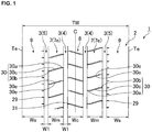
- FIG. 1 is an example of a development of a tread portion 2 of a tire 1 according to the embodiment of the present invention.
- the present invention can be used, for example, for various tires such as a pneumatic tire and a non-pneumatic tire the interior of which is not filled with pressurized air.
- the tire 1 of the present embodiment is a heavy-duty pneumatic tire.
- the tread portion 2 has a plurality of main grooves 3 continuously extending in the tire circumferential direction.
- the main grooves 3 include a pair of crown main grooves 4, 4 provided at both sides of a tire equator C, and a pair of shoulder main grooves 5, 5 provided between the crown main grooves 4 and tread edges Te.
- tread edges Te are defined as ground contact positions at the outermost side in the tire axial direction when a normal load is applied to the tire 1, in a normal state where the tire 1 is mounted to a normal rim and inflated to a normal internal pressure and no load is applied to the tire 1, such that the tire 1 is brought into contact with a plane at a camber angle of 0 degrees.
- the distance in the tire axial direction between both tread edges Te, Te is defined as a tread width TW. Unless otherwise specified, dimensions of components of the tire and the like are values measured in the normal state.
- the "normal rim” is a rim that is defined, in a standard system including a standard on which the tire is based, by the standard for each tire, and is, for example, the "standard rim” in the JATMA standard, the "Design Rim” in the TRA standard, or the “Measuring Rim” in the ETRTO standard.
- the "normal internal pressure” is an air pressure that is defined, in a standard system including a standard on which the tire is based, by the standard for each tire, and is the “maximum air pressure” in the JATMA standard, the maximum value indicated in the table "TIRE LOAD LIMITS AT VARIOUS COLD INFLATION PRESSURES" in the TRA standard, or the “INFLATION PRESSURE” in the ETRTO standard.
- the "normal load” is a load that is defined, in a standard system including a standard on which the tire is based, by the standard for each tire, and is the "maximum load capacity" in the JATMA standard, the "maximum value” indicated in the table "TIRE LOAD LIMITS AT VARIOUS COLD INFLATION PRESSURES" in the TRA standard, or the "LOAD CAPACITY” in the ETRTO standard.
- a groove width W1 of each main groove 3 is preferably, for example, 2 to 8% of the tread width TW.
- the tread portion 2 has a pair of middle land portions 7, 7 demarcated by the crown main grooves 4 and the shoulder main grooves 5, one crown land portion 8 demarcated between the crown main grooves 4, 4, and a pair of shoulder land portions 9, 9 demarcated between the shoulder main grooves 5 and the tread edges Te.
- Each middle land portion 7 has middle lateral grooves 30 connecting the crown main groove 4 and the shoulder main groove 5.
- Such middle lateral grooves 30 smoothly drain a water film on a tread surface 7e of the middle land portion 7 to the crown main groove 4 and the shoulder main groove 5.
- each middle lateral groove 30 includes a first portion 30a extending from the crown main groove 4 outward in the tire axial direction, a second portion 30b extending from the shoulder main groove 5 inward in the tire axial direction, and a third portion 30c connecting the first portion 30a and the second portion 30b.
- the third portion 30c is tilted at an angle larger than the angles of the first portion 30a and the second portion 30b relative to the tire axial direction.
- Such a third portion 30c has groove edges 30e each having a component in the tire axial direction and a component in the tire circumferential direction, and thus improves wet performance.
- the first portion 30a and the second portion 30b maintain high stiffness in the tire circumferential direction of the middle land portion 7.
- the crown land portion 8 has crown lateral grooves 31 connecting the crown main grooves 4, 4 at both sides of the tire equator C.
- the crown lateral grooves 31 are provided so as to be tilted in a direction opposite to that of the middle lateral grooves 30.
- the shoulder land portions 9 have a plurality of shoulder lateral grooves 29 that communicate with the shoulder main groove 5, terminate within the shoulder land portion 9, and extend along the tire axial direction.
- the shoulder lateral grooves 29 may be provided on one or each of the shoulder land portions 9, which are provided at the outermost side in the tire axial direction.
- the term "groove" is defined as a groove-like recess having a groove width of not less than 2 mm.
- a width Wc in the tire axial direction (mm) of the crown land portion 8, a width Wm in the tire axial direction (mm) of each middle land portion 7, and a width Ws in the tire axial direction (mm) of each shoulder land portion 9 satisfy the following formula (1).
- Wc : Wm : Ws 1.00 : 0.80 to 1.20 : 1.10 to 1.60
- Wc:Wm:Ws is preferably 1.00:0.80 to 1.20:1.30 to 1.60, and more preferably 1.00:0.90 to 1.10:1.35 to 1.50.
- the widths in the tire axial direction of the crown land portion, each middle land portion, and each shoulder land portion are the projection lengths in the tire axial direction of the crown land portion, each middle land portion, and each shoulder land portion, respectively, and are Wc, Wm, and Ws in FIG. 1 , respectively.
- a maximum length Lsm in the tire axial direction (mm) of the shoulder lateral grooves 29 and the width Ws in the tire axial direction (mm) of the shoulder land portion 9 satisfy the following formula (2). 0 ⁇ Lsm / Ws ⁇ 0.15 When formula (2) is satisfied, uneven wear resistance is improved. Preferably, 0.05 ⁇ Lsm/Ws ⁇ 0.09 is satisfied.
- FIG. 2 shows an enlarged view of the shoulder land portion 9 of the tread portion 2 in FIG. 1 .
- the plurality of shoulder lateral grooves 29 are provided on the shoulder land portion 9.
- the length in the tire axial direction of each shoulder lateral groove is the projection length in the tire axial direction of each shoulder lateral groove, and is L29 for the shoulder lateral groove 29 in FIG. 2 .
- the maximum length Lsm in the tire axial direction of the shoulder lateral grooves refers to the maximum length among the lengths in the tire axial direction of the respective shoulder lateral grooves.
- a total length Lst in the tire axial direction (mm) of the shoulder lateral grooves 29 and a tire outer diameter H (mm) satisfy the following formula (3).
- uneven wear resistance is improved.
- 0.80 ⁇ Lst/H ⁇ 2.00 is preferably satisfied, 0.90 ⁇ Lst/H ⁇ 1.40 is more preferably satisfied, and 1.00 ⁇ Lst/H ⁇ 1.30 is further preferably satisfied.
- the length in the tire axial direction of each shoulder lateral groove is the projection length in the tire axial direction of each shoulder lateral groove.
- the total length Lst in the tire axial direction of the shoulder lateral grooves is the total length (sum) of the lengths in the tire axial direction of the respective shoulder lateral grooves provided in the tread surface, and is the sum of the lengths in the tire axial direction of the respective shoulder lateral grooves such as L29 in FIG. 2 .
- the tire outer diameter H is the maximum outer diameter in the normal state when the tire is mounted to the normal rim and inflated to the normal internal pressure and no load is applied to the tire.
- a rubber composition that forms the tread portion 2 contains a rubber component containing 90% by mass or greater of an isoprene-based rubber. From the viewpoint of uneven wear resistance, the amount of the isoprene-based rubber in 100% by mass of the rubber component is not less than 90% by mass, but preferably not less than 95% by mass and more preferably 100% by mass.
- the isoprene-based rubber is not particularly limited as long as the isoprene-based rubber is a polymer having an isoprene-based unit as a main unit, and examples of the isoprene-based rubber include isoprene rubber (IR), epoxidized isoprene rubber, hydrogenated isoprene rubber, grafted isoprene rubber, natural rubber (NR), deproteinized natural rubber (DPNR), ultrapure natural rubber (UPNR), epoxidized natural rubber (ENR), hydrogenated natural rubber (HNR), and grafted natural rubber. These rubbers may be used individually, or two or more of these rubbers may be used in combination.
- Examples of a rubber component that can be blended, other than the isoprene-based rubber include diene-based rubbers such as butadiene rubber (BR), styrene-butadiene rubber (SBR), styrene-isoprene-butadiene rubber (SIBR), ethylene-propylene-diene rubber (EPDM), chloroprene rubber (CR), acrylonitrile butadiene rubber (NBR), and isobutylene-isoprene-rubber (IIR).
- the rubber components may be used individually, or two or more of rubber components may be used in combination. For example, BR and SBR are preferable.
- the SBR is not particularly limited, and, for example, an emulsion-polymerized styrene-butadiene rubber (E-SBR), a solution-polymerized styrene-butadiene rubber (S-SBR), and the like can be used.
- E-SBR emulsion-polymerized styrene-butadiene rubber
- S-SBR solution-polymerized styrene-butadiene rubber
- One of these styrene-butadiene rubbers may be used, or two or more of these styrene-butadiene rubbers may be used in combination.
- the SBR may be either an unmodified SBR or a modified SBR.
- the modified SBR only needs to be an SBR having a functional group that interacts with a filler such as silica
- examples of such a modified SBR include an end-modified SBR obtained by modifying at least one end of an SBR with a compound (modifier) having the functional group (an end-modified SBR having the functional group at an end thereof), a main chain-modified SBR having the functional group in the main chain thereof, a main chain/end-modified SBR having the functional group in the main chain and at an end thereof (for example, a main chain/end-modified SBR that has the functional group in the main chain thereof and in which at least one end thereof is modified with the modifier), and an end-modified SBR that is modified (coupled) by using a multifunctional compound having two or more epoxy groups in the molecule thereof and to which a hydroxyl group or an epoxy group is introduced.
- Examples of the above functional group include an amino group, an amide group, a silyl group, an alkoxysilyl group, an isocyanate group, an imino group, an imidazole group, a urea group, an ether group, a carbonyl group, an oxycarbonyl group, a mercapto group, a sulfide group, a disulfide group, a sulfonyl group, a sulfinyl group, a thiocarbonyl group, an ammonium group, an imide group, a hydrazo group, an azo group, a diazo group, a carboxyl group, a nitrile group, a pyridyl group, an alkoxy group, a hydroxyl group, an oxy group, and an epoxy group.
- These functional groups may have a substituent.
- an amino group preferably, an amino group obtained by substituting a hydrogen atom of an amino group with an alkyl group having 1 to 6 carbon atoms
- an alkoxy group preferably, an alkoxy group having 1 to 6 carbon atoms
- an alkoxysilyl group preferably, an alkoxysilyl group having 1 to 6 carbon atoms
- an amide group are preferable.
- modifier used for the modified SBR examples include: polyglycidyl ethers ofpolyhydric alcohols, such as ethylene glycol diglycidyl ether, glycerin triglycidyl ether, trimethylolethane triglycidyl ether, and trimethylolpropane triglycidyl ether; polyglycidyl ethers of aromatic compounds having two or more phenol groups, such as diglycidylated bisphenol A; polyepoxy compounds such as 1,4-diglycidylbenzene, 1,3,5-triglycidylbenzene, and polyepoxylated liquid polybutadiene; epoxy group-containing tertiary amines such as 4,4'-diglycidyl-diphenylmethylamine and 4,4'-diglycidyl-dibenzylmethylamine; diglycidylamino compounds such as diglycidylaniline, N,N'-diglycidyl-4-glycidyl
- amino group-containing acid chlorides such as bis-(1-methylpropyl)carbamic acid chloride, 4-morpholinecarbonyl chloride, 1-pyrrolidinecarbonyl chloride, N,N-dimethylcarbamic acid chloride, and N,N-diethylcarbamic acid chloride; epoxy group-containing silane compounds such as 1,3-bis-(glycidyloxypropyl)-tetramethyldisiloxane and (3-glycidyloxypropyl)-pentamethyldisiloxane;
- sulfide group-containing silane compounds such as (trimethylsilyl)[3-(trimethoxysilyl)propyl] sulfide, (trimethylsilyl) [3 -(triethoxysilyl)propyl] sulfide, (trimethylsilyl)[3-(tripropoxysilyl)propyl]sulfide, (trimethylsilyl)[3-(tributoxysilyl)propyl]sulfide, (trimethylsilyl)[3 -(methyldimethoxysilyl)propyl] sulfide, (trimethylsilyl) [3 - (methyldiethoxysilyl)propyl]sulfide, (trimethylsilyl)[3-(methyldipropoxysilyl)propyl]sulfide, and (trimethylsilyl)[3-(methyldibutoxysilyl)propyl]sulfide;
- N-substituted aziridine compounds such as ethyleneimine and propyleneimine; alkoxysilanes such as methyltriethoxysilane, N,N-bis(trimethylsilyl)-3-aminopropyltrimethoxysilane, N,N-bis(trimethylsilyl)-3-aminopropyltriethoxysilane, N,N-bis(trimethylsilyl)aminoethyltrimethoxysilane, and N,N-bis(trimethylsilyl)aminoethyltriethoxysilane; (thio)benzophenone compounds having an amino group and/or a substituted amino group, such as 4-N,N-dimethylaminobenzophenone, 4-N,N-dit-butylaminobenzophenone, 4-N,N-diphenylaminobenzophenone, 4,4'-bis(dimethylamino)benzophenone, 4,4'-bis(die
- Modification with the above compounds (modifiers) can be carried out by a known method.
- SBR for example, SBRs manufactured by and available from Sumitomo Chemical Co., Ltd., JSR Corporation, Asahi Kasei Corporation, Zeon Corporation, etc., can be used.
- the BR is not particularly limited, and a BR having a high cis content, a BR having a low cis content, a BR containing syndiotactic polybutadiene crystal, etc., can be used. These BRs may be used individually, or two or more of these BRs may be used in combination.
- the cis content of the BR is preferably not less than 90% by mass, more preferably not less than 95% by mass, and further preferably not less than 98% by mass.
- the upper limit of the cis content is not particularly limited. If the cis content falls within the above range, the effect tends to be more favorably achieved.
- the cis content of the BR can be measured by infrared absorption spectrometry.
- the BR may be either an unmodified BR or a modified BR.
- Examples of the modified BR include a modified BR into which the aforementioned functional group is introduced.
- BR for example, products of Ube Industries, Ltd., JSR Corporation, Asahi Kasei Corporation, Zeon Corporation, etc., can be used.
- the rubber composition contains carbon black having an average particle diameter of not greater than 20 nm and/or a cetyltrimethylammonium bromide adsorption specific surface area (CTAB) of not less than 130 m 2 /g (also referred to as carbon black (A)).
- CAB cetyltrimethylammonium bromide adsorption specific surface area
- the average particle diameter of the carbon black (A) is preferably not greater than 17 nm and more preferably not greater than 15 nm.
- the lower limit of the average particle diameter is not particularly limited, but, from the viewpoint of dispersibility and the like, the average particle diameter is preferably not less than 5 nm and more preferably not less than 10 nm.
- the average particle diameter of the carbon black is a number average particle diameter and is measured with a transmission electron microscope.
- the CTAB of the carbon black (A) is preferably not less than 140 m 2 /g, more preferably not less than 145 m 2 /g, and further preferably not less than 150 m 2 /g.
- the upper limit of the CTAB is not particularly limited, but, from the viewpoint of dispersibility and the like, the CTAB is preferably not greater than 250 m 2 /g, more preferably not greater than 200 m 2 /g, and further preferably not greater than 180 m 2 /g.
- the CTAB of the carbon black is a value measured according to JIS K6217-3: 2001.
- the nitrogen adsorption specific surface area (N 2 SA) of the carbon black (A) is preferably not less than 125 m 2 /g, more preferably not less than 145 m 2 /g, further preferably not less than 150 m 2 /g, and particularly preferably not less than 155 m 2 /g.
- the upper limit of the N 2 SA is not particularly limited, but, from the viewpoint of dispersibility and the like, the N 2 SA is preferably not greater than 250 m 2 /g, more preferably not greater than 200 m 2 /g, and further preferably not greater than 180 m 2 /g.
- the N 2 SA of the carbon black is obtained according to JIS K6217-2: 2001.
- the iodine adsorption amount (IA) (mg/g) of the carbon black (A) is preferably not less than 120 mg/g, more preferably not less than 125 mg/g, further preferably not less than 130 mg/g, and particularly preferably not less than 140 mg/g.
- the upper limit of the iodine adsorption amount (IA) is not particularly limited, but, from the viewpoint of dispersibility and the like, the iodine adsorption amount (IA) is preferably not greater than 200 mg/g, more preferably not greater than 180 mg/g, and further preferably not greater than 160 mg/g.
- the ratio (CTAB/IA) of the cetyltrimethylammonium bromide adsorption specific surface area (CTAB) to the iodine adsorption amount (IA) (mg/g) of the carbon black (A) is preferably 0.85 to 1.35 m 2 /mg, more preferably 0.92 to 1.30 m 2 /mg, and further preferably 1.00 to 1.25 m 2 /mg.
- the iodine adsorption amount (IA) of the carbon black is a value measured according to JIS K6217-1: 2001.
- a surface activity index represented by CTAB/IA can be considered as an index of the crystallinity (graphitization rate) of the carbon black. That is, higher CTAB/IA indicates that crystallization is less advanced, and the interaction between the carbon black and the rubber component tends to increase.
- CTAB/IA is also positioned as a parameter for evaluating the amount of acidic functional groups present on the surface of the carbon black. The acidic functional groups present on the surface of the carbon black contribute to the interaction with the rubber component, and higher CTAB/IA indicates that a larger number of acidic functional groups are present on the surface of the carbon black. Therefore, if the CTAB/IA is within the above range, a more significant reinforcing effect can be exerted on the rubber component, and excellent uneven wear resistance is achieved.
- the dibutyl phthalate absorption amount (DBP) of the carbon black (A) is preferably not less than 120 cm 3 /100 g, more preferably not less than 125 cm 3 /100 g, and further preferably not less than 135 cm 3 /100 g.
- the upper limit of the DBP is not particularly limited, but, from the viewpoint of dispersibility and the like, the DBP is preferably not greater than 180 cm 3 /100 g, more preferably not greater than 170 cm 3 /100 g, and further preferably not greater than 160 cm 3 /100 g.
- the DBP of the carbon black is measured according to JIS K 6217-4: 2001.
- Examples of the carbon black (A) include SAF, etc. These carbon blacks may be used individually, or two or more of these carbon blacks may be used in combination.
- the carbon black (A) can be produced by the production methods described in Japanese Laid-Open Patent Publication No. 2000-319539 , Japanese Laid-Open Patent Publication (translation of PCT application) No. H8-507555 , etc.
- the amount of the carbon black (A) in the rubber composition per 100 parts by mass of the rubber component is preferably not less than 5 parts by mass, more preferably not less than 10 parts by mass, further preferably not less than 20 parts by mass, and particularly preferably not less than 40 parts by mass. From the viewpoint of dispersibility and the like, this amount is preferably not greater than 100 parts by mass, more preferably not greater than 70 parts by mass, and further preferably not greater than 60 parts by mass.
- carbon black may be blended in the rubber composition together with the carbon black (A).
- the amount of the carbon black (A) in 100% by mass of the carbon black is preferably not less than 25% by mass, more preferably not less than 35% by mass, further preferably not less than 50% by mass, and particularly preferably not less than 80% by mass.
- the total amount of the carbon black (the total amount of the carbon black (A) and other carbon black blended as necessary) per 100 parts by mass of the rubber component is preferably not less than 10 parts by mass, more preferably not less than 20 parts by mass, further preferably not less than 30 parts by mass, and particularly preferably not less than 40 parts by mass. From the viewpoint of dispersibility and the like, this amount is preferably not greater than 120 parts by mass, more preferably not greater than 100 parts by mass, further preferably not greater than 70 parts by mass, and particularly preferably not greater than 60 parts by mass.
- a reinforcing filler that is generally used in production of a rubber composition, for example, silica, clay, talc, or the like, may be blended as appropriate in the rubber composition.
- the amount of the carbon black in 100% by mass of the reinforcing filler is preferably not less than 50% by mass, more preferably not less than 65% by mass, and further preferably not less than 75% by mass.
- the upper limit of the amount is not particularly limited, but the amount is preferably not greater than 98% by mass, more preferably not greater than 95% by mass, and further preferably not greater than 90% by mass.
- carbon black for example, commercially available products of Mitsubishi Chemical Corporation, Lion Corporation, NSCC Carbon Co., Ltd., Columbia Carbon Co., Cabot Japan K.K., etc., can be used. These carbon blacks may be used individually, or two or more of these carbon blacks may be used in combination.
- Silica may be blended in the rubber composition.
- the amount of the silica in the rubber composition per 100 parts by mass of the rubber component is preferably not less than 3.0 parts by mass and more preferably not less than 5.0 parts by mass. This amount is preferably not greater than 30 parts by mass, more preferably not greater than 20 parts by mass, and further preferably not greater than 15 parts by mass.
- the nitrogen adsorption specific surface area (N 2 SA) of the silica is preferably not less than 80 m 2 /g, more preferably not less than 115 m 2 /g, and further preferably not less than 150 m 2 /g.
- N 2 SA is set to be not less than the lower limit, good grip performance tends to be achieved.
- the N 2 SA is preferably not greater than 400 m 2 /g, more preferably not greater than 270 m 2 /g, and further preferably not greater than 250 m 2 /g.
- the N 2 SA is set to be not greater than the upper limit, good silica dispersibility tends to be achieved.
- the N 2 SA of the silica is a value measured by the BET method according to ASTM D3037-93.
- the silica is not particularly limited, and, for example, dry-process silica (anhydrous silica), wet-process silica (hydrous silica), etc., can be used, but wet-process silica is preferable for the reason that it has a higher silanol group content.
- dry-process silica anhydrous silica
- wet-process silica hydrophilic silica
- wet-process silica is preferable for the reason that it has a higher silanol group content.
- products of Degussa, Rhodia, Tosoh Silica Corporation, Solvay Japan, Ltd., Tokuyama Corporation, etc. can be used.
- One of these types of silica may be used individually, or two or more thereof may be used in combination.
- another filler other than the carbon black and the silica may be blended.
- the other filler include calcium carbonate, talc, alumina, clay, aluminum hydroxide, and mica.
- the rubber composition preferably contains silane coupling agent together with the silica.
- silane coupling agent any silane coupling agent that is conventionally used in combination with silica in the rubber industry can be used.
- the silane coupling agent is not particularly limited, and examples of the silane coupling agent include: sulfide silane coupling agents such as bis(3-triethoxysilylpropyl)tetrasulfide, bis(2-triethoxysilylethyl)tetrasulfide, bis(4-triethoxysilylbutyl)tetrasulfide, bis(3 -trimethoxysilylpropyl)tetrasulfide, bis(2-trimethoxysilylethyl)tetrasulfide, bis(2-triethoxysilylethyl)trisulfide, bis(4-trimethoxysilylbutyl)trisulfide, bis(3 -triethoxysilylpropyl)disulfide, bis(2-triethoxysilyleth
- silane coupling agents may be used individually, or two or more of these silane coupling agents may be used in combination. Among them, sulfide silane coupling agents and mercapto silane coupling agents are preferable.
- the amount of the silane coupling agent per 100 parts by mass of the silica is preferably not less than 2 parts by mass and more preferably not less than 5 parts by mass.
- the amount is set to be not less than the lower limit, the effect to be achieved by blending the silane coupling agent tends to be obtained.
- the amount is preferably not greater than 20 parts by mass and more preferably not greater than 15 parts by mass.
- the amount is set to be not greater than the upper limit, an effect corresponding to the blending amount is achieved, and good processability at the time of kneading tends to be achieved.
- a softener such as an oil and a liquid diene-based polymer may be blended.
- oil examples include process oils such as paraffinic, aromatic, and naphthenic process oils.
- the liquid diene-based polymer has a weight-average molecular weight (Mw) of preferably 1.0 ⁇ 10 3 to 2.0 ⁇ 10 5 and more preferably 3.0 ⁇ 10 3 to 1.5 ⁇ 10 4 , the weight-average molecular weight (Mw) being measured by gel permeation chromatography (GPC) in terms of polystyrene.
- Mw weight-average molecular weight
- GPC gel permeation chromatography
- the Mw of the liquid diene-based polymer is a value that is measured by gel permeation chromatography (GPC) and obtained by polystyrene conversion.
- liquid diene-based polymer examples include liquid styrene-butadiene copolymers (liquid SBRs), liquid butadiene polymers (liquid BRs), liquid isoprene polymers (liquid IRs), liquid styrene-isoprene copolymers (liquid SIRs), liquid styrene-butadiene-styrene block copolymers (liquid SBS block polymers), liquid styrene-isoprene-styrene block copolymers (liquid SIS block polymers), liquid farnesene polymers, and liquid farnesene- butadiene copolymers.
- the ends and the main chains of these polymers may be modified by polar groups. Among them, liquid IRs and liquid SBRs are preferable.
- the amount of the softener (softener total amount) per 100 parts by mass of the rubber component is preferably 1 to 100 parts by mass and more preferably 5 to 50 parts by mass.
- the amount of the softener also includes the amount of oil included in oil-extended rubber.
- a resin in solid form at normal temperature (25°C) may be blended.
- the amount of the resin per 100 parts by mass of the rubber component is preferably 3 to 50 parts by mass and more preferably 7 to 40 parts by mass.
- the resin examples include aromatic vinyl polymers, coumarone-indene resins, indene resins, rosin-based resins, terpene-based resins, and acrylic-based resins.
- aromatic vinyl polymers coumarone-indene resins, indene resins, rosin-based resins, terpene-based resins, and acrylic-based resins.
- These resins may be used individually, or two or more of these resins may be
- the above aromatic vinyl polymers may be resins obtained by polymerizing ⁇ -methylstyrene and/or styrene, and examples of such a resin include styrene homopolymers, ⁇ -methylstyrene homopolymers, and copolymers of ⁇ -methylstyrene and styrene. Among them, copolymers of ⁇ -methylstyrene and styrene are preferable.
- the above coumarone-indene resins refer to resins that contain coumarone and indene as main monomer components that form the backbone (main chain) of the resins.
- the monomer components included in the backbone other than coumarone and indene include styrene, ⁇ -methylstyrene, methylindene, and vinyltoluene.
- indene resins refer to resins that contain indene as a main monomer component that forms the backbone (main chain) of the resins.
- rosin-based resins can be classified depending on whether the rosins are modified or not, that is, can be classified into non-modified rosins (unmodified rosins) and modified rosin products (rosin derivatives).
- non-modified rosins include tall rosin (also called tall oil rosin), gum rosin, wood rosin, disproportionated rosins, polymerized rosins, hydrogenated rosins, and other chemically modified rosins.
- Modified rosins are obtained by modifying non-modified rosins, and examples of modified rosin products include rosin esters, unsaturated carboxylic acid-modified rosins, unsaturated carboxylic acid-modified rosin esters, amide compounds of rosins, and amine salts of rosins.
- the rosin-based resins preferably have a carboxyl group content not excessively high and preferably have an appropriate acid value.
- the acid values of rosin-based resins ordinarily exceed 0 mg KOH/g, e.g., and is, for example, not greater than 200 mg KOH/g, preferably not greater than 100 mg KOH/g, more preferably not greater than 30 mg KOH/g, and further preferably not greater than 10 mg KOH/g.
- the acid values can be measured in accordance with Examples described later.
- the acid value can be adjusted to fall within the above range by reducing the carboxyl groups of the rosin through known esterification treatment.
- terpene-based resins a polyterpene resin obtained by polymerizing a terpene compound, an aromatic modified terpene resin obtained by polymerizing a terpene compound and an aromatic compound, etc., can be used. Moreover, hydrogenated products of these resins can also be used.
- the above polyterpene resin is a resin that is obtained by polymerizing a terpene compound.
- the terpene compound is a hydrocarbon represented by a composition (C 5 H 8 ) n and an oxygenated derivative thereof, and is a compound having, as the basic backbone, a terpene classified into monoterpene (C 10 H 16 ), sesquiterpene (C 15 H 24 ), diterpene (C 20 H 32 ), and the like.
- terpene compound examples include ⁇ -pinene, ⁇ -pinene, dipentene, limonene, myrcene, allo-ocimene, ocimene, ⁇ -phellandrene, ⁇ -terpinene, ⁇ -terpinene, terpinolene, 1,8-cineole, 1,4-cineole, ⁇ -terpineol, ⁇ -terpineol, and ⁇ -terpineol.
- Examples of the above polyterpene resins include pinene resins, limonene resins, dipentene resins, and pinene-limonene resins which are formed from the above-described terpene compounds.
- pinene resins are preferable since a polymerization reaction is easy and since natural pine resin is a raw material and thus the cost is low.
- pinene resins contain both ⁇ -pinene and ⁇ -pinene, which are isomeric with each other. Depending on contained components, pinene resins are classified into ⁇ -pinene resins containing ⁇ -pinene as a main component, and ⁇ -pinene resins containing ⁇ -pinene as a main component.
- Examples of the above aromatic modified terpene resin include terpene-phenol resins formed from the above terpene compounds and phenol-based compounds, and terpene-styrene resins formed from the above terpene compounds and styrene-based compounds. Moreover, terpene-phenol-styrene resins formed from the above terpene compounds, phenol-based compounds, and styrene-based compounds can also be used. Examples of phenol-based compounds include phenol, bisphenol A, cresol, and xylenol. Examples of styrene-based compounds include styrene and ⁇ -methylstyrene.
- the rubber composition preferably contains sulfur (sulfur vulcanization agent).
- Examples of the sulfur include powdery sulfur, precipitated sulfur, colloidal sulfur, insoluble sulfur, highly dispersible sulfur, and soluble sulfur, which are generally used in the rubber industry.
- products of Tsurumi Chemical Industry Co., Ltd., Karuizawa Sulfur Co, Ltd., SHIKOKU CHEMICALS CORPORATION, Flexsys, Nippon Kanryu Industry Co., Ltd., Hosoi Chemical Industry Co., Ltd., etc. can be used. These sulfurs may be used individually, or two or more of these sulfurs may be used in combination.
- the amount of the sulfur (sulfur vulcanization agent) per 100 parts by mass of the rubber component is preferably not less than 0.3 parts by mass, more preferably not less than 0.5 parts by mass, and further preferably not less than 0.8 parts by mass.
- the upper limit of the amount is not particularly limited, but the amount is preferably not greater than 5.0 parts by mass, more preferably not greater than 3.0 parts by mass, and further preferably not greater than 2.5 parts by mass.
- the rubber composition preferably contains a vulcanization accelerator.
- vulcanization accelerator examples include: thiazole-based vulcanization accelerators such as 2-mercaptobenzothiazole, di-2-benzothiazolyl disulfide (DM (2,2'-dibenzothiazolyl disulfide)), and N-cyclohexyl-2-benzothiazyl sulfenamide; thiuram-based vulcanization accelerators such as tetramethylthiuram disulfide (TMTD), tetrabenzylthiuram disulfide (TBzTD), and tetrakis (2-ethylhexyl)thiuram disulfide (TOT-N); sulfenamide-based vulcanization accelerators such as N-cyclohexyl-2-benzothiazole sulfenamide, N-t-butyl-2-benzothiazolyl sulfenamide, N-oxyethylene-2-benzothiazole sulfenamide, and N,N'
- vulcanization accelerators may be used individually, or two or more of these vulcanization accelerators may be used in combination. Among them, sulfenamide-based vulcanization accelerators and guanidine-based vulcanization accelerators are preferable.
- the amount of the vulcanization accelerator per 100 parts by mass of the rubber component is preferably not less than 0.5 parts by mass, more preferably not less than 1.0 part by mass, and further preferably not less than 1.3 parts by mass.
- the amount is preferably not greater than 8.0 parts by mass, more preferably not greater than 5.0 parts by mass, and further preferably not greater than 3.0 parts by mass.
- the rubber composition may contain a wax.
- the wax is not particularly limited, and examples of the wax include: petroleum waxes such as paraffin wax and microcrystalline wax; natural waxes such as vegetable wax and animal wax; and synthesized waxes such as polymers of ethylene, propylene, and the like.
- petroleum waxes such as paraffin wax and microcrystalline wax
- natural waxes such as vegetable wax and animal wax
- synthesized waxes such as polymers of ethylene, propylene, and the like.
- products of Ouchi Shinko Chemical Industrial Co., Ltd., NIPPON SEIRO CO., LTD., Seiko Chemical Co., Ltd., etc. can be used. These waxes may be used individually, or two or more of these waxes may be used in combination.
- petroleum waxes are preferable, and paraffin wax is more preferable.
- the amount of the wax per 100 parts by mass of the rubber component is preferably not less than 0.5 parts by mass and more preferably not less than 1 part by mass. Meanwhile, the amount is preferably not greater than 10 parts by mass and more preferably not greater than 6 parts by mass.
- the rubber composition may contain an antioxidant.
- the antioxidant is not particularly limited, and examples of the antioxidant include: naphthylamine antioxidants such as phenyl- ⁇ -naphthylamine; diphenylamine antioxidants such as octylated diphenylamine and 4,4'-bis( ⁇ , ⁇ '-dimethylbenzyl)diphenylamine; p-phenylenediamine antioxidants such as N-isopropyl-N'-phenyl-p-phenylenediamine, N-(1,3-dimethylbutyl)-N' -phenyl-p-phenylenediamine, and N,N' -di-2-naphthyl-p-phenylenediamine; quinoline antioxidants such as a polymer of 2,2,4-trimethyl-1,2-dihydroquinoline; monophenol antioxidants such as 2,6-di-t-butyl-4-methylphenol and styrenated phenol; and bis-, tris-, and poly-phenol antioxidant
- antioxidants As commercially available products, products of Seiko Chemical Co., Ltd., Sumitomo Chemical Co., Ltd., Ouchi Shinko Chemical Industrial Co., Ltd., Flexsys, etc., can be used. These antioxidants may be used individually, or two or more of these antioxidants may be used in combination. Among them, p-phenylenediamine antioxidants (more preferably N-(1,3-dimethylbutyl)-N'-phenyl-p-phenylenediamine) are preferable.
- the amount of the antioxidant per 100 parts by mass of the rubber component is preferably not less than 0.3 parts by mass, more preferably not less than 1 part by mass, further preferably not less than 1.5 parts by mass, and particularly preferably not less than 2.5 parts by mass.
- the amount is preferably not greater than 7 parts by mass, more preferably not greater than 6 parts by mass, further preferably not greater than 5 parts by mass, and particularly preferably not greater than 4 parts by mass.
- the rubber composition may contain a fatty acid, particularly stearic acid.
- stearic acid conventionally known stearic acids can be used.
- products of NOF Corporation, Kao Corporation, FUJIFILM Wako Pure Chemical Corporation, New Japan Chemical Co., Ltd., etc. can be used.
- the amount of the fatty acid per 100 parts by mass of the rubber component is preferably not less than 0.5 parts by mass and more preferably not less than 1 part by mass. Meanwhile, the amount is preferably not greater than 10 parts by mass and more preferably not greater than 5 parts by mass.
- the rubber composition may contain zinc oxide.
- zinc oxide conventionally known zinc oxides can be used.
- products of Mitsui Mining & Smelting Co., Ltd., Toho Zinc Co., Ltd., HAKUSUI TECH CO., LTD., SEIDO CHEMICAL INDUSTRY CO., LTD., Sakai Chemical Industry Co., Ltd., etc. can be used.
- the amount of the zinc oxide per 100 parts by mass of the rubber component is preferably not less than 0.5 parts by mass and more preferably not less than 1 part by mass. Meanwhile, the amount is preferably not greater than 5 parts by mass and more preferably not greater than 4 parts by mass.
- additives that are generally used in the tire industry can be blended in the rubber composition, and examples of the additives include surfactants.
- the rubber composition can be produced by a method in which the components are kneaded by using a rubber kneading device such as an open roll, a Banbury mixer, or a kneader, and then vulcanization is performed.
- a rubber kneading device such as an open roll, a Banbury mixer, or a kneader
- the kneading temperature is normally 100 to 180°C and preferably 120 to 170°C.
- the kneading temperature is normally not higher than 120°C and preferably 85 to 110°C.
- a composition obtained by kneading the vulcanizing agent and the vulcanization accelerator is normally subjected to vulcanization processing such as press vulcanization.
- the vulcanization temperature is normally 140 to 190°C and preferably 150 to 185°C.
- the heavy-duty tire according to the present invention is produced by a general method using the above rubber composition.
- the rubber composition obtained by blending the above components is extruded in an unvulcanized state so as to correspond to the shape of, for example, a tread (a member, which is brought into contact with a road surface, such as a single-layer tread or a cap tread of a multilayer tread), and is formed together with other tire members on a tire forming machine by a general method, thereby forming an unvulcanized tire.
- the unvulcanized tire is heated and pressurized in a vulcanizing machine, thereby obtaining the tire.
- the tire can be used for trucks, buses, etc.
- Carbon black 1 was produced under each condition, using C fuel oil as fuel and creosote oil as raw material hydrocarbon, with use of a carbon black reactor in which a combustion zone with an inner diameter of 800 mm and a length of 1600 mm provided with an air introduction duct and a combustion burner, a raw material introduction zone connected from the combustion zone and composed of a narrow diameter portion with an inner diameter of 145 mm and a length of 1000 mm to which a material nozzle is connected by penetration from the periphery thereof, and a rear reaction zone with an inner diameter of 400 mm and a length of 3000 mm provided with a quenching device are sequentially joined.
- a carbon black reactor in which a combustion zone with an inner diameter of 800 mm and a length of 1600 mm provided with an air introduction duct and a combustion burner, a raw material introduction zone connected from the combustion zone and composed of a narrow diameter portion with an inner diameter of 145 mm and a length of 1000 mm to which a material nozzle is connected by penetration from the
- Carbon black 3 was produced by the production method of Example 3 in Japanese Laid-Open Patent Publication (translation of PCT application) No. H8-507555 .
- the chemicals other than the sulfur and the vulcanization accelerator were kneaded under a condition of 150°C for 5 minutes by using a 1.7-L Banbury mixer manufactured by Kobe Steel, Ltd., to obtain a kneaded product.
- the sulfur and the vulcanization accelerator were added to the obtained kneaded product, and the mixture was kneaded under a condition of 80°C for 5 minutes by using an open roll, to obtain an unvulcanized rubber composition.
- the obtained unvulcanized rubber composition was press-vulcanized at 170°C for 20 minutes to obtain a vulcanized rubber sheet.
- the obtained unvulcanized rubber composition was formed into the shape of a tread according to the basic pattern shown in Table 1, and attached together with other tire members to produce an unvulcanized tire, and the unvulcanized tire was press-vulcanized under a condition of 170°C for 10 minutes to obtain a test tire (size: 295/80R22.5 (for trucks and buses)).
- a volume loss amount of each vulcanized rubber sheet was measured using a LAT tester (Laboratory Abrasion and Skid Tester) under conditions of a load of 40 N, a speed of 20 km/h, and a slip angle of 5°.
- the ratio (%) of the volume loss amount of each composition to the volume loss amount of Comparative Example 2 is indicated as an index. A higher index indicates that the wear resistance is better.
- test tires were mounted to rims and attached to eight wheels of a 2-axle trailer towed by a 2DD vehicle, the vehicle was caused to run on a test course with an asphalt road surface, and the wear amount of each middle land portion was measured.
- the above vehicle having the test tires attached thereto was caused to run for a total of 30,000 km on a general road, and then the groove depth of each main groove of the tires was measured.
- the groove depth is indicated as an index with the value of Comparative Example 1 being regarded as 100. A higher value indicates that the result is better.
- the uneven wear resistance and the tire total life were significantly excellent in the Examples in each of which the heavy-duty tire includes a tread portion having predetermined crown main grooves, predetermined shoulder main grooves, a predetermined crown land portion, predetermined middle land portions, predetermined shoulder land portions, and predetermined shoulder lateral grooves, the above formulas (1) to (3) are satisfied, and the tread portion is formed from a rubber composition containing an isoprene-based rubber and predetermined carbon black in predetermined blending amounts.
Landscapes
- Chemical & Material Sciences (AREA)
- Health & Medical Sciences (AREA)
- Chemical Kinetics & Catalysis (AREA)
- Medicinal Chemistry (AREA)
- Polymers & Plastics (AREA)
- Organic Chemistry (AREA)
- Engineering & Computer Science (AREA)
- Mechanical Engineering (AREA)
- Tires In General (AREA)
- Compositions Of Macromolecular Compounds (AREA)
Applications Claiming Priority (1)
| Application Number | Priority Date | Filing Date | Title |
|---|---|---|---|
| JP2018187558A JP7110887B2 (ja) | 2018-10-02 | 2018-10-02 | 重荷重用タイヤ |
Publications (2)
| Publication Number | Publication Date |
|---|---|
| EP3632702A1 true EP3632702A1 (fr) | 2020-04-08 |
| EP3632702B1 EP3632702B1 (fr) | 2021-04-07 |
Family
ID=68072214
Family Applications (1)
| Application Number | Title | Priority Date | Filing Date |
|---|---|---|---|
| EP19200011.5A Active EP3632702B1 (fr) | 2018-10-02 | 2019-09-27 | Pneu pour fonctionnement intensif |
Country Status (2)
| Country | Link |
|---|---|
| EP (1) | EP3632702B1 (fr) |
| JP (1) | JP7110887B2 (fr) |
Cited By (1)
| Publication number | Priority date | Publication date | Assignee | Title |
|---|---|---|---|---|
| EP3738998A1 (fr) * | 2019-05-17 | 2020-11-18 | Sumitomo Rubber Industries, Ltd. | Composition de bande de roulement en caoutchouc et pneumatique |
Citations (5)
| Publication number | Priority date | Publication date | Assignee | Title |
|---|---|---|---|---|
| JPH08507555A (ja) | 1993-02-23 | 1996-08-13 | キャボット コーポレイション | カーボンブラック |
| EP0949303A1 (fr) * | 1998-04-09 | 1999-10-13 | Degussa-Hüls Aktiengesellschaft | Noir fourneau amélioré et son procédé de fabrication |
| JP2000319539A (ja) | 1999-03-11 | 2000-11-21 | Mitsubishi Chemicals Corp | カーボンブラック及びゴム組成物 |
| JP2011161988A (ja) | 2010-02-05 | 2011-08-25 | Sumitomo Rubber Ind Ltd | 重荷重用タイヤ |
| EP2444257A1 (fr) * | 2009-06-15 | 2012-04-25 | Bridgestone Corporation | Pneumatique très résistant |
Family Cites Families (8)
| Publication number | Priority date | Publication date | Assignee | Title |
|---|---|---|---|---|
| JP3049291B2 (ja) * | 1991-08-23 | 2000-06-05 | 株式会社ブリヂストン | 空気入りタイヤ |
| JP3226968B2 (ja) * | 1992-07-20 | 2001-11-12 | 株式会社ブリヂストン | 空気入りタイヤ |
| JPH06184362A (ja) * | 1992-12-22 | 1994-07-05 | Toyo Tire & Rubber Co Ltd | トラック・バス用ラジアルタイヤのトレッド構造 |
| JPH07109382A (ja) * | 1993-10-13 | 1995-04-25 | Yokohama Rubber Co Ltd:The | 重荷重ラジアルタイヤトレッド用ゴム組成物 |
| JP4713785B2 (ja) | 2001-08-23 | 2011-06-29 | 株式会社ブリヂストン | 空気入りタイヤ |
| JP5151066B2 (ja) | 2006-05-22 | 2013-02-27 | 横浜ゴム株式会社 | 空気入りタイヤ |
| JP4705684B2 (ja) | 2009-02-06 | 2011-06-22 | 住友ゴム工業株式会社 | 重荷重用タイヤ |
| JP2017101132A (ja) | 2015-11-30 | 2017-06-08 | 住友化学株式会社 | ゴム組成物および加硫ゴム組成物 |
-
2018
- 2018-10-02 JP JP2018187558A patent/JP7110887B2/ja active Active
-
2019
- 2019-09-27 EP EP19200011.5A patent/EP3632702B1/fr active Active
Patent Citations (5)
| Publication number | Priority date | Publication date | Assignee | Title |
|---|---|---|---|---|
| JPH08507555A (ja) | 1993-02-23 | 1996-08-13 | キャボット コーポレイション | カーボンブラック |
| EP0949303A1 (fr) * | 1998-04-09 | 1999-10-13 | Degussa-Hüls Aktiengesellschaft | Noir fourneau amélioré et son procédé de fabrication |
| JP2000319539A (ja) | 1999-03-11 | 2000-11-21 | Mitsubishi Chemicals Corp | カーボンブラック及びゴム組成物 |
| EP2444257A1 (fr) * | 2009-06-15 | 2012-04-25 | Bridgestone Corporation | Pneumatique très résistant |
| JP2011161988A (ja) | 2010-02-05 | 2011-08-25 | Sumitomo Rubber Ind Ltd | 重荷重用タイヤ |
Cited By (1)
| Publication number | Priority date | Publication date | Assignee | Title |
|---|---|---|---|---|
| EP3738998A1 (fr) * | 2019-05-17 | 2020-11-18 | Sumitomo Rubber Industries, Ltd. | Composition de bande de roulement en caoutchouc et pneumatique |
Also Published As
| Publication number | Publication date |
|---|---|
| JP7110887B2 (ja) | 2022-08-02 |
| JP2020055427A (ja) | 2020-04-09 |
| EP3632702B1 (fr) | 2021-04-07 |
Similar Documents
| Publication | Publication Date | Title |
|---|---|---|
| US11299605B2 (en) | Heavy duty pneumatic tire | |
| EP3608125B1 (fr) | Composition de caoutchouc pour bande de roulement et pneumatique | |
| EP3865313B1 (fr) | Pneumatique | |
| JP7517527B2 (ja) | トレッド用ゴム組成物及びタイヤ | |
| EP3919289A1 (fr) | Pneumatique | |
| EP3626481B1 (fr) | Pneumatique | |
| EP3744776A1 (fr) | Composition de caoutchouc pour pneumatiques | |
| EP3851488B1 (fr) | Composition de caoutchouc pour bande de roulement et pneumatique | |
| EP3572240B1 (fr) | Composition de caoutchouc pour bande de roulement et pneumatique | |
| EP3632702B1 (fr) | Pneu pour fonctionnement intensif | |
| JP7516944B2 (ja) | タイヤ用ゴム組成物及びタイヤ | |
| JP7225637B2 (ja) | ゴム組成物及び空気入りタイヤ | |
| JP7135438B2 (ja) | タイヤ用ゴム組成物及び空気入りタイヤ | |
| EP3608127B1 (fr) | Pneumatique | |
| JP7306050B2 (ja) | タイヤ用ゴム組成物及び空気入りタイヤ | |
| JP2021172173A (ja) | タイヤ | |
| JP2023061490A (ja) | 空気入りタイヤ | |
| EP4209360A1 (fr) | Pneumatique | |
| WO2022025008A1 (fr) | Pneumatique | |
| EP3650493A2 (fr) | Composition de caoutchouc de bande de roulement et pneumatique | |
| JP2021088305A (ja) | 二輪車用タイヤ |
Legal Events
| Date | Code | Title | Description |
|---|---|---|---|
| PUAI | Public reference made under article 153(3) epc to a published international application that has entered the european phase |
Free format text: ORIGINAL CODE: 0009012 |
|
| STAA | Information on the status of an ep patent application or granted ep patent |
Free format text: STATUS: THE APPLICATION HAS BEEN PUBLISHED |
|
| AK | Designated contracting states |
Kind code of ref document: A1 Designated state(s): AL AT BE BG CH CY CZ DE DK EE ES FI FR GB GR HR HU IE IS IT LI LT LU LV MC MK MT NL NO PL PT RO RS SE SI SK SM TR |
|
| AX | Request for extension of the european patent |
Extension state: BA ME |
|
| STAA | Information on the status of an ep patent application or granted ep patent |
Free format text: STATUS: REQUEST FOR EXAMINATION WAS MADE |
|
| 17P | Request for examination filed |
Effective date: 20200929 |
|
| RBV | Designated contracting states (corrected) |
Designated state(s): AL AT BE BG CH CY CZ DE DK EE ES FI FR GB GR HR HU IE IS IT LI LT LU LV MC MK MT NL NO PL PT RO RS SE SI SK SM TR |
|
| GRAP | Despatch of communication of intention to grant a patent |
Free format text: ORIGINAL CODE: EPIDOSNIGR1 |
|
| STAA | Information on the status of an ep patent application or granted ep patent |
Free format text: STATUS: GRANT OF PATENT IS INTENDED |
|
| INTG | Intention to grant announced |
Effective date: 20201113 |
|
| GRAS | Grant fee paid |
Free format text: ORIGINAL CODE: EPIDOSNIGR3 |
|
| GRAA | (expected) grant |
Free format text: ORIGINAL CODE: 0009210 |
|
| STAA | Information on the status of an ep patent application or granted ep patent |
Free format text: STATUS: THE PATENT HAS BEEN GRANTED |
|
| AK | Designated contracting states |
Kind code of ref document: B1 Designated state(s): AL AT BE BG CH CY CZ DE DK EE ES FI FR GB GR HR HU IE IS IT LI LT LU LV MC MK MT NL NO PL PT RO RS SE SI SK SM TR |
|
| REG | Reference to a national code |
Ref country code: GB Ref legal event code: FG4D |
|
| REG | Reference to a national code |
Ref country code: AT Ref legal event code: REF Ref document number: 1379192 Country of ref document: AT Kind code of ref document: T Effective date: 20210415 Ref country code: CH Ref legal event code: EP |
|
| REG | Reference to a national code |
Ref country code: DE Ref legal event code: R096 Ref document number: 602019003765 Country of ref document: DE |
|
| REG | Reference to a national code |
Ref country code: IE Ref legal event code: FG4D |
|
| REG | Reference to a national code |
Ref country code: LT Ref legal event code: MG9D |
|
| REG | Reference to a national code |
Ref country code: NL Ref legal event code: MP Effective date: 20210407 Ref country code: AT Ref legal event code: MK05 Ref document number: 1379192 Country of ref document: AT Kind code of ref document: T Effective date: 20210407 |
|
| PG25 | Lapsed in a contracting state [announced via postgrant information from national office to epo] |
Ref country code: LT Free format text: LAPSE BECAUSE OF FAILURE TO SUBMIT A TRANSLATION OF THE DESCRIPTION OR TO PAY THE FEE WITHIN THE PRESCRIBED TIME-LIMIT Effective date: 20210407 Ref country code: HR Free format text: LAPSE BECAUSE OF FAILURE TO SUBMIT A TRANSLATION OF THE DESCRIPTION OR TO PAY THE FEE WITHIN THE PRESCRIBED TIME-LIMIT Effective date: 20210407 Ref country code: FI Free format text: LAPSE BECAUSE OF FAILURE TO SUBMIT A TRANSLATION OF THE DESCRIPTION OR TO PAY THE FEE WITHIN THE PRESCRIBED TIME-LIMIT Effective date: 20210407 Ref country code: BG Free format text: LAPSE BECAUSE OF FAILURE TO SUBMIT A TRANSLATION OF THE DESCRIPTION OR TO PAY THE FEE WITHIN THE PRESCRIBED TIME-LIMIT Effective date: 20210707 Ref country code: AT Free format text: LAPSE BECAUSE OF FAILURE TO SUBMIT A TRANSLATION OF THE DESCRIPTION OR TO PAY THE FEE WITHIN THE PRESCRIBED TIME-LIMIT Effective date: 20210407 Ref country code: NL Free format text: LAPSE BECAUSE OF FAILURE TO SUBMIT A TRANSLATION OF THE DESCRIPTION OR TO PAY THE FEE WITHIN THE PRESCRIBED TIME-LIMIT Effective date: 20210407 |
|
| PG25 | Lapsed in a contracting state [announced via postgrant information from national office to epo] |
Ref country code: IS Free format text: LAPSE BECAUSE OF FAILURE TO SUBMIT A TRANSLATION OF THE DESCRIPTION OR TO PAY THE FEE WITHIN THE PRESCRIBED TIME-LIMIT Effective date: 20210807 Ref country code: GR Free format text: LAPSE BECAUSE OF FAILURE TO SUBMIT A TRANSLATION OF THE DESCRIPTION OR TO PAY THE FEE WITHIN THE PRESCRIBED TIME-LIMIT Effective date: 20210708 Ref country code: PL Free format text: LAPSE BECAUSE OF FAILURE TO SUBMIT A TRANSLATION OF THE DESCRIPTION OR TO PAY THE FEE WITHIN THE PRESCRIBED TIME-LIMIT Effective date: 20210407 Ref country code: NO Free format text: LAPSE BECAUSE OF FAILURE TO SUBMIT A TRANSLATION OF THE DESCRIPTION OR TO PAY THE FEE WITHIN THE PRESCRIBED TIME-LIMIT Effective date: 20210707 Ref country code: LV Free format text: LAPSE BECAUSE OF FAILURE TO SUBMIT A TRANSLATION OF THE DESCRIPTION OR TO PAY THE FEE WITHIN THE PRESCRIBED TIME-LIMIT Effective date: 20210407 Ref country code: SE Free format text: LAPSE BECAUSE OF FAILURE TO SUBMIT A TRANSLATION OF THE DESCRIPTION OR TO PAY THE FEE WITHIN THE PRESCRIBED TIME-LIMIT Effective date: 20210407 Ref country code: RS Free format text: LAPSE BECAUSE OF FAILURE TO SUBMIT A TRANSLATION OF THE DESCRIPTION OR TO PAY THE FEE WITHIN THE PRESCRIBED TIME-LIMIT Effective date: 20210407 Ref country code: PT Free format text: LAPSE BECAUSE OF FAILURE TO SUBMIT A TRANSLATION OF THE DESCRIPTION OR TO PAY THE FEE WITHIN THE PRESCRIBED TIME-LIMIT Effective date: 20210809 |
|
| REG | Reference to a national code |
Ref country code: DE Ref legal event code: R097 Ref document number: 602019003765 Country of ref document: DE |
|
| PG25 | Lapsed in a contracting state [announced via postgrant information from national office to epo] |
Ref country code: SK Free format text: LAPSE BECAUSE OF FAILURE TO SUBMIT A TRANSLATION OF THE DESCRIPTION OR TO PAY THE FEE WITHIN THE PRESCRIBED TIME-LIMIT Effective date: 20210407 Ref country code: ES Free format text: LAPSE BECAUSE OF FAILURE TO SUBMIT A TRANSLATION OF THE DESCRIPTION OR TO PAY THE FEE WITHIN THE PRESCRIBED TIME-LIMIT Effective date: 20210407 Ref country code: EE Free format text: LAPSE BECAUSE OF FAILURE TO SUBMIT A TRANSLATION OF THE DESCRIPTION OR TO PAY THE FEE WITHIN THE PRESCRIBED TIME-LIMIT Effective date: 20210407 Ref country code: DK Free format text: LAPSE BECAUSE OF FAILURE TO SUBMIT A TRANSLATION OF THE DESCRIPTION OR TO PAY THE FEE WITHIN THE PRESCRIBED TIME-LIMIT Effective date: 20210407 Ref country code: CZ Free format text: LAPSE BECAUSE OF FAILURE TO SUBMIT A TRANSLATION OF THE DESCRIPTION OR TO PAY THE FEE WITHIN THE PRESCRIBED TIME-LIMIT Effective date: 20210407 Ref country code: RO Free format text: LAPSE BECAUSE OF FAILURE TO SUBMIT A TRANSLATION OF THE DESCRIPTION OR TO PAY THE FEE WITHIN THE PRESCRIBED TIME-LIMIT Effective date: 20210407 Ref country code: SM Free format text: LAPSE BECAUSE OF FAILURE TO SUBMIT A TRANSLATION OF THE DESCRIPTION OR TO PAY THE FEE WITHIN THE PRESCRIBED TIME-LIMIT Effective date: 20210407 |
|
| PLBE | No opposition filed within time limit |
Free format text: ORIGINAL CODE: 0009261 |
|
| STAA | Information on the status of an ep patent application or granted ep patent |
Free format text: STATUS: NO OPPOSITION FILED WITHIN TIME LIMIT |
|
| 26N | No opposition filed |
Effective date: 20220110 |
|
| REG | Reference to a national code |
Ref country code: BE Ref legal event code: MM Effective date: 20210930 |
|
| PG25 | Lapsed in a contracting state [announced via postgrant information from national office to epo] |
Ref country code: IS Free format text: LAPSE BECAUSE OF FAILURE TO SUBMIT A TRANSLATION OF THE DESCRIPTION OR TO PAY THE FEE WITHIN THE PRESCRIBED TIME-LIMIT Effective date: 20210807 Ref country code: MC Free format text: LAPSE BECAUSE OF FAILURE TO SUBMIT A TRANSLATION OF THE DESCRIPTION OR TO PAY THE FEE WITHIN THE PRESCRIBED TIME-LIMIT Effective date: 20210407 Ref country code: AL Free format text: LAPSE BECAUSE OF FAILURE TO SUBMIT A TRANSLATION OF THE DESCRIPTION OR TO PAY THE FEE WITHIN THE PRESCRIBED TIME-LIMIT Effective date: 20210407 |
|
| PG25 | Lapsed in a contracting state [announced via postgrant information from national office to epo] |
Ref country code: LU Free format text: LAPSE BECAUSE OF NON-PAYMENT OF DUE FEES Effective date: 20210927 Ref country code: IT Free format text: LAPSE BECAUSE OF FAILURE TO SUBMIT A TRANSLATION OF THE DESCRIPTION OR TO PAY THE FEE WITHIN THE PRESCRIBED TIME-LIMIT Effective date: 20210407 Ref country code: IE Free format text: LAPSE BECAUSE OF NON-PAYMENT OF DUE FEES Effective date: 20210927 Ref country code: BE Free format text: LAPSE BECAUSE OF NON-PAYMENT OF DUE FEES Effective date: 20210930 |
|
| REG | Reference to a national code |
Ref country code: CH Ref legal event code: PL |
|
| P01 | Opt-out of the competence of the unified patent court (upc) registered |
Effective date: 20230510 |
|
| PG25 | Lapsed in a contracting state [announced via postgrant information from national office to epo] |
Ref country code: CY Free format text: LAPSE BECAUSE OF FAILURE TO SUBMIT A TRANSLATION OF THE DESCRIPTION OR TO PAY THE FEE WITHIN THE PRESCRIBED TIME-LIMIT Effective date: 20210407 |
|
| PG25 | Lapsed in a contracting state [announced via postgrant information from national office to epo] |
Ref country code: LI Free format text: LAPSE BECAUSE OF NON-PAYMENT OF DUE FEES Effective date: 20220930 Ref country code: HU Free format text: LAPSE BECAUSE OF FAILURE TO SUBMIT A TRANSLATION OF THE DESCRIPTION OR TO PAY THE FEE WITHIN THE PRESCRIBED TIME-LIMIT; INVALID AB INITIO Effective date: 20190927 Ref country code: CH Free format text: LAPSE BECAUSE OF NON-PAYMENT OF DUE FEES Effective date: 20220930 |
|
| PGFP | Annual fee paid to national office [announced via postgrant information from national office to epo] |
Ref country code: FR Payment date: 20230808 Year of fee payment: 5 Ref country code: DE Payment date: 20230802 Year of fee payment: 5 |
|
| PG25 | Lapsed in a contracting state [announced via postgrant information from national office to epo] |
Ref country code: MK Free format text: LAPSE BECAUSE OF FAILURE TO SUBMIT A TRANSLATION OF THE DESCRIPTION OR TO PAY THE FEE WITHIN THE PRESCRIBED TIME-LIMIT Effective date: 20210407 |
|
| GBPC | Gb: european patent ceased through non-payment of renewal fee |
Effective date: 20230927 |
|
| PG25 | Lapsed in a contracting state [announced via postgrant information from national office to epo] |
Ref country code: GB Free format text: LAPSE BECAUSE OF NON-PAYMENT OF DUE FEES Effective date: 20230927 |
|
| PG25 | Lapsed in a contracting state [announced via postgrant information from national office to epo] |
Ref country code: GB Free format text: LAPSE BECAUSE OF NON-PAYMENT OF DUE FEES Effective date: 20230927 |