EP3632640B1 - Treatment plant for a flexible material sheet which can be passed through a treatment furnace, especially a plastic film - Google Patents
Treatment plant for a flexible material sheet which can be passed through a treatment furnace, especially a plastic film Download PDFInfo
- Publication number
- EP3632640B1 EP3632640B1 EP19199676.8A EP19199676A EP3632640B1 EP 3632640 B1 EP3632640 B1 EP 3632640B1 EP 19199676 A EP19199676 A EP 19199676A EP 3632640 B1 EP3632640 B1 EP 3632640B1
- Authority
- EP
- European Patent Office
- Prior art keywords
- zone
- wall
- nozzle
- material web
- neutral zone
- Prior art date
- Legal status (The legal status is an assumption and is not a legal conclusion. Google has not performed a legal analysis and makes no representation as to the accuracy of the status listed.)
- Active
Links
- 239000000463 material Substances 0.000 title claims description 83
- 239000002985 plastic film Substances 0.000 title claims description 44
- 229920006255 plastic film Polymers 0.000 title claims description 44
- 230000007935 neutral effect Effects 0.000 claims description 78
- 239000012530 fluid Substances 0.000 claims description 71
- 238000011144 upstream manufacturing Methods 0.000 claims description 7
- 238000007664 blowing Methods 0.000 claims description 3
- 238000000605 extraction Methods 0.000 claims 10
- 230000000712 assembly Effects 0.000 claims 1
- 238000000429 assembly Methods 0.000 claims 1
- 239000003570 air Substances 0.000 description 45
- 230000000694 effects Effects 0.000 description 14
- 238000001816 cooling Methods 0.000 description 12
- 238000005192 partition Methods 0.000 description 9
- 230000008901 benefit Effects 0.000 description 7
- 238000000638 solvent extraction Methods 0.000 description 7
- 238000000137 annealing Methods 0.000 description 6
- 238000010438 heat treatment Methods 0.000 description 6
- 238000004519 manufacturing process Methods 0.000 description 3
- 230000007704 transition Effects 0.000 description 3
- 239000012080 ambient air Substances 0.000 description 2
- 230000000903 blocking effect Effects 0.000 description 2
- 238000010276 construction Methods 0.000 description 2
- 238000013461 design Methods 0.000 description 2
- 238000007667 floating Methods 0.000 description 2
- 239000007789 gas Substances 0.000 description 2
- 239000011261 inert gas Substances 0.000 description 2
- 239000002184 metal Substances 0.000 description 2
- 229910000831 Steel Inorganic materials 0.000 description 1
- 238000013459 approach Methods 0.000 description 1
- QVGXLLKOCUKJST-UHFFFAOYSA-N atomic oxygen Chemical compound [O] QVGXLLKOCUKJST-UHFFFAOYSA-N 0.000 description 1
- 230000004888 barrier function Effects 0.000 description 1
- 230000006866 deterioration Effects 0.000 description 1
- 230000002349 favourable effect Effects 0.000 description 1
- 210000004907 gland Anatomy 0.000 description 1
- 230000006872 improvement Effects 0.000 description 1
- 238000003780 insertion Methods 0.000 description 1
- 230000037431 insertion Effects 0.000 description 1
- 238000000034 method Methods 0.000 description 1
- 239000001301 oxygen Substances 0.000 description 1
- 229910052760 oxygen Inorganic materials 0.000 description 1
- 230000008569 process Effects 0.000 description 1
- 230000009467 reduction Effects 0.000 description 1
- 238000007789 sealing Methods 0.000 description 1
- 238000000926 separation method Methods 0.000 description 1
- 230000006641 stabilisation Effects 0.000 description 1
- 238000011105 stabilization Methods 0.000 description 1
- 239000010959 steel Substances 0.000 description 1
- 230000001629 suppression Effects 0.000 description 1
- 238000012360 testing method Methods 0.000 description 1
- 238000012546 transfer Methods 0.000 description 1
- 238000010792 warming Methods 0.000 description 1
Images


Classifications
-
- B—PERFORMING OPERATIONS; TRANSPORTING
- B29—WORKING OF PLASTICS; WORKING OF SUBSTANCES IN A PLASTIC STATE IN GENERAL
- B29C—SHAPING OR JOINING OF PLASTICS; SHAPING OF MATERIAL IN A PLASTIC STATE, NOT OTHERWISE PROVIDED FOR; AFTER-TREATMENT OF THE SHAPED PRODUCTS, e.g. REPAIRING
- B29C35/00—Heating, cooling or curing, e.g. crosslinking or vulcanising; Apparatus therefor
- B29C35/02—Heating or curing, e.g. crosslinking or vulcanizing during moulding, e.g. in a mould
- B29C35/04—Heating or curing, e.g. crosslinking or vulcanizing during moulding, e.g. in a mould using liquids, gas or steam
- B29C35/045—Heating or curing, e.g. crosslinking or vulcanizing during moulding, e.g. in a mould using liquids, gas or steam using gas or flames
-
- B—PERFORMING OPERATIONS; TRANSPORTING
- B05—SPRAYING OR ATOMISING IN GENERAL; APPLYING FLUENT MATERIALS TO SURFACES, IN GENERAL
- B05B—SPRAYING APPARATUS; ATOMISING APPARATUS; NOZZLES
- B05B13/00—Machines or plants for applying liquids or other fluent materials to surfaces of objects or other work by spraying, not covered by groups B05B1/00 - B05B11/00
- B05B13/02—Means for supporting work; Arrangement or mounting of spray heads; Adaptation or arrangement of means for feeding work
- B05B13/0278—Arrangement or mounting of spray heads
-
- B—PERFORMING OPERATIONS; TRANSPORTING
- B29—WORKING OF PLASTICS; WORKING OF SUBSTANCES IN A PLASTIC STATE IN GENERAL
- B29C—SHAPING OR JOINING OF PLASTICS; SHAPING OF MATERIAL IN A PLASTIC STATE, NOT OTHERWISE PROVIDED FOR; AFTER-TREATMENT OF THE SHAPED PRODUCTS, e.g. REPAIRING
- B29C35/00—Heating, cooling or curing, e.g. crosslinking or vulcanising; Apparatus therefor
- B29C35/02—Heating or curing, e.g. crosslinking or vulcanizing during moulding, e.g. in a mould
- B29C35/04—Heating or curing, e.g. crosslinking or vulcanizing during moulding, e.g. in a mould using liquids, gas or steam
- B29C35/06—Heating or curing, e.g. crosslinking or vulcanizing during moulding, e.g. in a mould using liquids, gas or steam for articles of indefinite length
-
- B—PERFORMING OPERATIONS; TRANSPORTING
- B29—WORKING OF PLASTICS; WORKING OF SUBSTANCES IN A PLASTIC STATE IN GENERAL
- B29C—SHAPING OR JOINING OF PLASTICS; SHAPING OF MATERIAL IN A PLASTIC STATE, NOT OTHERWISE PROVIDED FOR; AFTER-TREATMENT OF THE SHAPED PRODUCTS, e.g. REPAIRING
- B29C37/00—Component parts, details, accessories or auxiliary operations, not covered by group B29C33/00 or B29C35/00
- B29C37/0089—Sealing devices placed between articles and treatment installations during moulding or shaping, e.g. sealing off the entrance or exit of ovens or irradiation rooms, connections between rooms at different pressures
-
- F—MECHANICAL ENGINEERING; LIGHTING; HEATING; WEAPONS; BLASTING
- F27—FURNACES; KILNS; OVENS; RETORTS
- F27B—FURNACES, KILNS, OVENS, OR RETORTS IN GENERAL; OPEN SINTERING OR LIKE APPARATUS
- F27B9/00—Furnaces through which the charge is moved mechanically, e.g. of tunnel type; Similar furnaces in which the charge moves by gravity
- F27B9/02—Furnaces through which the charge is moved mechanically, e.g. of tunnel type; Similar furnaces in which the charge moves by gravity of multiple-track type; of multiple-chamber type; Combinations of furnaces
- F27B9/028—Multi-chamber type furnaces
-
- F—MECHANICAL ENGINEERING; LIGHTING; HEATING; WEAPONS; BLASTING
- F27—FURNACES; KILNS; OVENS; RETORTS
- F27B—FURNACES, KILNS, OVENS, OR RETORTS IN GENERAL; OPEN SINTERING OR LIKE APPARATUS
- F27B9/00—Furnaces through which the charge is moved mechanically, e.g. of tunnel type; Similar furnaces in which the charge moves by gravity
- F27B9/28—Furnaces through which the charge is moved mechanically, e.g. of tunnel type; Similar furnaces in which the charge moves by gravity for treating continuous lengths of work
-
- B—PERFORMING OPERATIONS; TRANSPORTING
- B29—WORKING OF PLASTICS; WORKING OF SUBSTANCES IN A PLASTIC STATE IN GENERAL
- B29C—SHAPING OR JOINING OF PLASTICS; SHAPING OF MATERIAL IN A PLASTIC STATE, NOT OTHERWISE PROVIDED FOR; AFTER-TREATMENT OF THE SHAPED PRODUCTS, e.g. REPAIRING
- B29C71/00—After-treatment of articles without altering their shape; Apparatus therefor
- B29C71/02—Thermal after-treatment
- B29C2071/022—Annealing
-
- B—PERFORMING OPERATIONS; TRANSPORTING
- B29—WORKING OF PLASTICS; WORKING OF SUBSTANCES IN A PLASTIC STATE IN GENERAL
- B29C—SHAPING OR JOINING OF PLASTICS; SHAPING OF MATERIAL IN A PLASTIC STATE, NOT OTHERWISE PROVIDED FOR; AFTER-TREATMENT OF THE SHAPED PRODUCTS, e.g. REPAIRING
- B29C55/00—Shaping by stretching, e.g. drawing through a die; Apparatus therefor
- B29C55/02—Shaping by stretching, e.g. drawing through a die; Apparatus therefor of plates or sheets
- B29C55/10—Shaping by stretching, e.g. drawing through a die; Apparatus therefor of plates or sheets multiaxial
- B29C55/12—Shaping by stretching, e.g. drawing through a die; Apparatus therefor of plates or sheets multiaxial biaxial
-
- B—PERFORMING OPERATIONS; TRANSPORTING
- B29—WORKING OF PLASTICS; WORKING OF SUBSTANCES IN A PLASTIC STATE IN GENERAL
- B29C—SHAPING OR JOINING OF PLASTICS; SHAPING OF MATERIAL IN A PLASTIC STATE, NOT OTHERWISE PROVIDED FOR; AFTER-TREATMENT OF THE SHAPED PRODUCTS, e.g. REPAIRING
- B29C71/00—After-treatment of articles without altering their shape; Apparatus therefor
- B29C71/02—Thermal after-treatment
Definitions
- the invention relates to a treatment system for a flexible material web that can be passed through a treatment furnace, in particular in the form of a plastic film, according to the preamble of claim 1.
- Treatment systems of this type are often film stretching systems which are used in particular in the production of plastic films.
- simultaneous stretching systems are known, in which a plastic film can be stretched simultaneously in the longitudinal and transverse directions.
- sequential stretching systems are also known, in which the plastic film is stretched in two successive stages, for example first in the longitudinal direction and then in the transverse direction (or vice versa).
- pure longitudinal and pure transverse stretching systems are also known.
- the material web to be stretched is gripped at the two opposite film edges by means of clips which are arranged to be movable on circumferential guide rails on both sides of the material web to be stretched.
- the clips are successively moved from an inlet zone (in which the edge of a plastic film to be stretched, for example, is gripped) via a stretching zone (in which the opposing clips on the guide rail sections with a transverse component are moved away from each other diverging to the transport direction) to an outlet zone and then up proceed a way back to the inlet zone, with the film downstream of the stretching zone in one or more treatment zones (annealing zone, cooling zone), for example still being subjected to a certain relaxation and / or post-heat treatment.
- annealing zone, cooling zone for example still being subjected to a certain relaxation and / or post-heat treatment.
- the plastic film Before, during and after the actual stretching process, the plastic film must be subjected to a different heating and cooling phase in the individual sections.
- the plastic film web to be stretched therefore passes through an oven which has successively different treatment zones (possibly also neutral zones in between). In these treatment zones, the plastic film to be produced is not only subjected to a different heat treatment, but above all an oven air supply must be provided in order to always supply the oven interior of the stretching system with fresh air and to suck out the polluted air.
- the plastic film i.e. generally the flexible material web
- the plastic film emerges from one zone and enters a next zone, in which the material web may be treated in others Temperatures takes place.
- a stretching system is divided into several zones.
- a preheating zone a stretching zone, an annealing zone and a cooling zone can be provided.
- the preheating and stretching zone can also be designed as a common zone.
- the cooling zones (but also basically other zones) can be divided into several separate zones, for example into a first and second cooling zone, which are provided in succession, and a third cooling zone at the end of the stretching system, which z. B. is separated by a neutral zone provided between the second and the third cooling zone.
- a neutral zone can, for example, also be provided between the stretching zone and the annealing zone (and then also at other points).
- an entry and exit slit (sometimes also called an entry and an exit slit) is provided for the stretching furnace by moving plastic film.
- the individual zones can also comprise a plurality of chambers, such as the annealing zone, for example, which can have a plurality of chambers.
- the plastic film emerges from a slot-shaped opening in a treatment zone, it takes corresponding fluid with it from the treatment zone through this slot, the fluid having a corresponding zone temperature.
- the fluid carried along is namely at a treatment temperature that is not optimal for this subsequent treatment chamber, because the fluid introduced accordingly is either too hot or too cool and changes the set treatment chamber temperature.
- the different pressure levels in the furnace as a whole result in an additional superimposed basic flow, which also increases the fluid exchange between the treatment chambers and / or between the treatment chambers of a subsequent neutral zone or a neutral zone and a subsequent treatment chamber.
- a basic flow arises due to the dragging effect of the film and / or the existing pressure differences in the furnace, which can lead to zones with an "incorrect temperature".
- hot air can flow into a cold oven zone or, conversely, cold air can flow into a hot oven zone.
- neutral zones can be provided anywhere between two treatment zones, for example between the stretching zone and the annealing zone or, for example, between the annealing zone and the cooling zone and in some cases also before the last cooling zone.
- a partitioning device for a stretching system in particular a stretching system for plastic film webs, has been proposed, in which treatment zones that are offset from one another in the pull-off direction of the film web are formed. These each have an entry or exit slit through which the film web to be peeled off enters or exits.
- a floating nozzle is described, whereby a gap delimitation specified for the film entry or exit is intended to be limited in its effect.
- this nozzle outlet opening is directed essentially tangentially to the film web and / or allows a flow of the gaseous medium flowing out through the nozzle outlet opening that is essentially tangential to the plane of the film web, the gap delimitation formed on the side of the film web opposite the floating nozzle being adjustable in its shoulder to the film web should be.
- An intermediate zone is provided between the two chambers.
- Air is circulated in each of the two treatment chambers, an adjacent air layer being moved along with the material web through the treatment chambers and thereby being moved out of the first chamber.
- a specific device is provided in the intermediate zone, in which an air layer is generated that runs obliquely onto the moving material web, in the opposite direction to the pull-off direction of the material web.
- EP 1 441 192 A2 describes a device for replacing the oxygen in the air with an inert gas from a laminar air boundary layer. It is shown that a separate inert gas distributor is provided for this, which is arranged downstream of a treatment zone and which is provided with a nozzle outlet opening pointing towards the material web and ending at a small distance from it. This nozzle outlet opening is closer to the material web than the lower end of the actual wall of the upstream treatment chamber.
- a partitioning device for a treatment zone in particular in the form of a treatment or stretching furnace for to create moving material webs, in particular in the form of a plastic film web to be stretched.
- appropriately adjustable partition walls are used at least at the transition from a treatment zone to a neutral zone and / or at the transition from a neutral zone to a treatment zone, for example in the form of adjustable or hinged metal sheets (which are sometimes also referred to below as “shutters” or referred to as “air shutter”).
- shutters adjustable or hinged metal sheets
- air shutter air shutter
- a shutter is therefore an adjusting device that delimits the height of the gap for the film to be let through and is adjustable as a kind Shutter, adjustment and / or shutter or aperture can be designated.
- an air curtain or air curtain is impressed, which, in the withdrawal direction of the moving material web, preferably after an outlet gap from a treatment zone into a neutral zone and / or is preferably provided or positioned in front of an inlet gap at the transition from a neutral zone to a treatment zone.
- a flat air jet is generated, which is placed on the partition wall (shutter plate), so that the course of the partition walls then serves as a further baffle or guide plate in order to guide the gaseous media jet directed onto it in the direction of the moving material web stabilize.
- the air jet runs more or less in the area adjacent to the material web parallel to the partition wall (shutter plate), more or less perpendicularly up to the plane of the moving material web, so as to "block the entry and / or exit gap" ".
- no gaseous medium can enter a treatment zone (at least in a relevant amount) in the area of the inlet gap or emerge from a treatment zone in the area of an outlet gap
- the underside of the moving material web is provided, i.e. on both opposite sides of the moving material web, the partition walls provided on the input and output sides preferably being designed as continuous walls, the entry or exit gap of which is at least slightly wider than the width of the material web being moved through.
- the gaseous media jet which is sometimes referred to as fluid steel in the following, acts like a barrier flow with respect to the furnace base flow and thus prevents air from flowing in from a neutral zone or flowing out into a neutral zone. Above all, this also prevents a gaseous medium from escaping from a treatment zone, for example flowing through a subsequent neutral zone and being introduced via the inlet gap of a subsequent further treatment zone.
- the effect and the effects can alternatively or also cumulatively be further improved in addition to the above-mentioned solution in that the gaseous fluid jet area is blown onto the moving material web at a temperature which is more or less identical to the temperature of the adjacent preceding and / or subsequent zone.
- the flow speed of the emitter can be varied depending on the application. Speeds in the range of 5 - 25 m / s have proven to be particularly favorable.
- the advantages of the invention include, on the one hand, the aforementioned reduction or suppression of the basic furnace flow (across the entry or exit gaps of the corresponding zones), i.e. also a stabilization of the moving material web, in particular in the case of a plastic film. This also applies in particular when a plastic film, for example, passes through a corresponding shutter gap (inlet or outlet gap).
- the air shutter provided according to the invention would be in the manner of a so-called free fluid jet at a safe distance between the moving material web on the one hand and the delimiting edge running adjacent to it (which delimits an entry or exit gap). In this way, damage to the moving material web can be prevented, in particular in the case of a plastic film web or a film tear.
- Another advantage of the solution according to the invention is that a defined heat transfer is possible due to the defined air shutter beam which is stable over the working width and which can be referred to as a fan-shaped or rather flat gaseous beam. This can be used to heat or cool the moving material web to a predetermined temperature level, for example, particularly in the case of a plastic film web.
- the invention can be used in a wide variety of systems.
- the air shutter principle according to the invention can be used in all film stretching systems with film heating by hot air. It has also been shown that the solution according to the invention can be implemented both with simultaneous and with sequential film stretching systems or with pure longitudinal or transverse stretching systems and leads to the desired advantages. Tests have also shown that the advantages according to the invention can be achieved even if the moving material web is moved through the individual zones at different speeds, for example at more than 50 m / min, the advantages also being realizable when the speeds are above the above-mentioned values have been increased, for example up to 700 m / min.
- the slightly inclined blowing on the shutter partitions usually at an angle of less than 45 °, preferably less than 40 °, 35 °, 30 °, 25 °, 20 °, 15 ° or even Less than 10 °, similar to the heating or cooling devices used in the individual zones (or ovens), can take place by means of air nozzle boxes, which are operated or heated by fans and heat exchangers.
- the suction of the gaseous fluid jet can, for example, be implemented centrally via an exit area provided in a ceiling construction of the system remote from the plastic film web, or also, for example, via separate suction boxes.
- it is also possible to provide the suction for the gaseous fluid jet centrally below the plastic film web for example via a floor construction located at a distance from a plastic film web.
- the gaseous fluid flow used usually in the form of air, it is not necessary to adhere to specific limit values or parameters. At most, the temperature of the gaseous fluid flow / air is critical, since the effects can be further improved as a function of the temperatures. It is entirely possible that, for example, air from a respective adjacent zone is also used, or that, for example, heated fresh air is used in order to be blown in the direction of the plastic film web by means of the air shutter device.
- the device for generating an air-shutter-air or generally gaseous fluid flow can for example take place via slot nozzles, but also via hole nozzles, whereby the production of the nozzle box for such a shutter blowing is further simplified.
- Combinations of, for example, hole and slit glands are also possible.
- the introduced gaseous medium is sucked off either in close proximity to the fluid film or at some distance from it.
- the suction should take place within this. This results in the characteristic fluid flow rollers, which additionally stabilize the blocking flow jet.
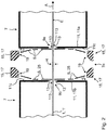
- a system 3 is shown in a schematic longitudinal section, in particular a film stretching system 3 ', with a stretching oven 3 ", with a material web 1 being moved through the film stretching system 3' and thus through the stretching oven 3" in the take-off direction A, ie for example a plastic film 1 '.
- the system 3, in particular in the form of a film stretching system 3 ', can be a simultaneous stretching system or a sequential stretching system in which longitudinal and transverse stretching are not carried out simultaneously (as with the simultaneous stretching system), but first in longitudinal and then in the transverse direction or vice versa. In principle, it can also be a transverse stretching system.
- a corresponding system comprises, for example, a corresponding housing structure 5 with a plurality of successive zones 7.
- the zones 7 are usually treatment zones 7 which are separated from one another by a neutral zone 7n.
- the individual treatment zones can be not just one, but for example two or generally more treatment chambers 7 '. All treatment zones 7 thereby form the stretching furnace 3 ′′ through which the moving material web 1, in particular in the form of the plastic film 1 ′, passes through.
- the structure is usually symmetrical to the plane E, on which the moving material web 1 is moved away.
- asymmetrical structures are also possible.
- the individual treatment zones 7 each have an entrance gap 9a on the entrance side and an exit gap 9b on the exit side, which are dimensioned so high and so wide that the material web 1 passes through this slot arrangement without touching the delimiting edges of the entrance and / or exit gap or slot 9a, 9b can be moved through in order to avoid damage to the material web, in particular in the form of the plastic film.
- the plastic film film in particular moved through, can be heated to different temperatures in the individual zones.
- So-called neutral zones 7n can also be provided between the individual zones in order to separate two successive zones more strongly from one another so that no gaseous treatment fluid can easily pass from one zone 7 into a subsequent next zone 7.
- various measures are provided according to the invention.
- the individual treatment zones 7 have zone walls 11, i.e. usually a zone entry wall 11a and a zone exit wall 11b, which in the following can also be referred to as shutter wall, shutter boundary wall or shutter sheet metal.
- the mentioned entry and exit gaps 9a, 9b are provided in these zone walls 11, with - based on the in Figure 2
- the neutral zone 7n shown - the slot or gap leading in the film running direction A is referred to as the exit gap 9b and the gap provided in the withdrawal direction after the neutral zone 7n in the subsequent entry zone wall 11a is referred to as the entry gap 9a.
- the gaps each have delimiting edges running essentially parallel to plane E of the moving material web 1, namely delimiting edges 13 that generally run parallel to plane E. These delimiting edges should approach the film plane E as much as possible, around the height H of the slot arrangement as low as possible to keep. The lower the slot height H, the less gaseous fluid can enter from one treatment zone or into a next treatment zone.
- the corresponding zone walls 11 or what are known as shutters or shutter plates are therefore preferred 113 can be adjusted differently, if necessary, in such a way that their delimiting edges 113 'can be set at an optimal distance from the plane E of the moving material web.
- the zone walls 11 in the form of the shutter boundary walls or shutter plates are aligned perpendicular or essentially perpendicular to the plane E of the moving material web and run perpendicular to the material web 1, i.e. perpendicular to the plane E of the plastic film 1 'and thus also perpendicular to the reference direction A of the material web 1.
- a nozzle arrangement 15 is arranged adjacent to a shutter plate 11, namely outside the actual treatment zones 7. In the case of the neutral zone 7n, the two nozzle arrangements 15 are provided in the neutral zone 7n.
- the nozzle arrangements 15 have a nozzle device 17 with a nozzle outlet opening 19, whereby a gaseous fluid jet S is generated, which is at a blow angle ⁇ is aligned with the adjoining zone wall 11, ie with the adjoining shutter boundary wall or the shutter plate.
- the blow angle ⁇ should be comparatively small, usually set below 45 °. Preferred values are below 40 °, 35 °, 30 °, 25 °, 20 ° and in particular below 15 ° or even below 12.5 °, 10 °, 8 °, 7 °, 6 °, 5 °, 4 °, 3 °, 2 °, or less than 1 °, the angle usually being greater than or equal to 0 °.
- the fluid flow S also strikes the material web 1 more or less perpendicularly, as shown in FIG Figure 2 is shown schematically. According to the orientation of the surface 11c of the shutter wall 11 or the shutter wall 11 itself, the angle of incidence of the fluid flow S with respect to the plane E of the material web 1 is more or less fixed.
- the fluid jet S moves up to the lower boundary edge 13 of a shutter plate 11 and over the lower delimiting edge 13 in the direction of the material web 1 until the fluid jet S strikes the film plane E more or less directly.
- the nozzle arrangements 15 and / or the nozzle devices 17 and / or the nozzle outlet openings 19 are therefore designed and / or arranged and / or aligned in such a way that the respective gaseous fluid flow S is directed to the zone outlet wall 11b or to the leading neutral zone wall 113b ( Figure 3 and 4th ) or the zone entry wall 11a and / or to the trailing neutral zone wall 113a ( Figure 3 and 4th ) is brought in and / or laid or applied so that the gaseous fluid flow S after impinging on the respective wall of the zone outlet wall 11b or the leading neutral zone wall 113b or the zone inlet wall 11a and / or the trailing neutral zone wall 113a following up to the Material web 1 flows.
- a flat air jet is generated that is placed on the corresponding walls, e.g. the partitioning wall (shutter plate), so that the course of these walls or partitioning walls then serves as a guide or guide plate around the one directed thereon to guide and stabilize the gaseous media jet in the direction of the moving material web.
- the air jet runs more or less in the area adjacent to the material web parallel to the partition wall (shutter plate), more or less perpendicularly up to the plane of the moving material web, so as to "block the entry and / or exit gap"".
- the gaseous fluid flow S is in each case heated to a temperature range which corresponds to the temperature in the respective adjacent treatment zone 7.
- the gaseous fluid flow S to close the outlet gap 9b is preferably also heated to this temperature range T 1.
- this gaseous fluid flow S in the area of the inlet gap 9a of the subsequent treatment zone 7 is also preferably heated to this temperature range T 2 , i.e. the gaseous fluid flow S is preferred to be heated to that temperature which corresponds to the temperature of the gaseous flowing around in the subsequent treatment zone 7 Fluids (usually air) corresponds.
- the heated gaseous fluid flow S should preferably be less than 20 ° C., in particular less than 15 ° C., less than 12.5 ° C.
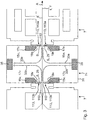
- a neutral zone 7n which is likewise delimited by a housing arrangement 31, is in turn provided between a treatment zone 7 leading in the withdrawal direction A and a trailing treatment zone 7.
- a first nozzle arrangement 15v with a nozzle device 17v with nozzle outlet openings 19v is shown in a schematic cross-sectional representation, as well as a further nozzle arrangement 15n with a nozzle device, which is arranged trailing and adjacent to the subsequent inlet gap 9a of a subsequent zone 7 17n, which has a nozzle outlet opening 19n.
- the nozzle arrangement 15 and / or the nozzle outlet opening (19v, 19n) is designed such that it extends over the entire width of the material web 1 or deviates from it by less than +/- 20% and in particular by less than +/- 10%.
- the gaseous fluid flow S moved over the respective delimiting edge 113 'of the shutter or shutter plate 113, which can be adjusted in its distance in the direction of the material web 1, to the film plane E is then deflected according to the arrows 33a and 33b.
- the gaseous fluid flow S which is generated by a leading nozzle arrangement 15v with regard to a treatment zone 7 located upstream in the take-off direction A of the plastic film, is deflected in the take-off direction A of the film according to arrow representation 33b, and then possibly guided away from the material web plane E approximately in the middle area of the neutral zone 7n up to a suction device 35 located at a distance from the material web.
- the gaseous fluid flow S generated by the downstream zone 7 in take-off direction A is moved in the opposite direction to the take-off direction A of the film in the neutral zone 7n, avoiding entry through the entry gap 9a into the following zone 7, until it is also approximately in the middle of the neutral zone 7n is moved away from the film plane E according to the arrow representation 33a, specifically up to the suction device 35, which is also mentioned.
- the two suction devices 35 can be selected to be very different in terms of their design and arrangement.
- the path of the suction direction and the direction of flow of the gaseous fluid flow S is similar in both cases, however, since the nozzle arrangement 15v arranged in front in the withdrawal direction in the neutral zone 7n generates a fluid flow which initially runs in the withdrawal direction A of the plastic film in order to move towards the suction device 35a to be led away, whereas the nozzle arrangement 15n arranged downstream in the neutral zone 7n (which is assigned to a subsequent treatment zone 7) initially flows in the opposite direction to the film removal direction A along the film plane E, in order then to be deflected into the rear area at the rear of the nozzle box, where the corresponding Suction device 35b is arranged.
- the nozzle and discharge devices are preferably also accommodated in the mentioned housing device 31, which for example also have neutral zones and walls 113a and 113b offset from one another in the discharge direction A, the inlet and outlet devices. are arranged on the output side in relation to the withdrawal direction A of the material web 1.
- These neutral zone walls 113a, 113b preferably run parallel to the respectively adjoining chamber inlet and chamber outlet walls 11a, 11b, even if these - as in Figure 3 and Figure 4 is shown - have a side distance in the withdrawal direction A to each other in their predominant height.
- a wall section is then preferably provided at least at a partial height adjacent to plane E, which can either be part of a chamber wall 11a, 11b of a zone 7 and / or also part of the neutral zone walls 113, ie specifically the neutral zone walls 113a , 113b.
- This wall section is then fed so far onto the film plane E that the respective entry gap 9a or exit gap 9b is formed between the opposing delimiting edges 13.
- Gaseous fluids located in an upstream zone 7 could escape via this, which is to be prevented by the shutter device.
- the fluid flow S will run predominantly perpendicular to the plane E over its path, in the area of the gap opening to the adjacent leading one or the trailing zone, however, may be deflected slightly obliquely to the plane E of the material web 1.
- a suction area 39 is also drawn in, which corresponds, for example, to the suction opening 39 in the suction device 35.
- the suction opening 39 is arranged at the level of the nozzle opening 37a or 37b in order to make it clear that the suction opening 39 for the various variants of the suction device 35 can be provided in different designs, for example in the neutral zone 7n.
- the nozzle openings mentioned can, however, also be designed higher or lower, so that the suction openings 39 then lie at a different relative height with respect to the nozzle opening.
- the nozzle arrangement is such that the gaseous fluid flow at the level of the material web 1 or at least also at the level of the entry or exit gap 9a, 9b extends so wide in the transverse direction of the material web 1 that the fluid flow across the entire width of the material web 1 hits and thereby covers about half the gap height remaining on each side of the material web, so that this gaseous fluid flow covers the respective inlet or outlet gap and is thus quasi “closed” by this gaseous fluid flow.
- the nozzle arrangement is therefore provided or arranged in the transverse direction over the material web 1 with such a width that the gaps are completely covered by the fluid flow.
- outlet nozzles it is also possible, however, for the outlet nozzles to be provided and / or designed only with a smaller width in relation to the material web, but then as flat or be split in a fan shape that the fluid flow is fanned out at least at the level of the inlet and / or outlet gaps 9a, 9b so that the gaps are quasi closed by this gaseous fluid flow moving towards the material web.
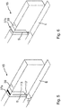
- FIG. 7 is different to Figures 5 and 6 a variant is shown in which a corresponding nozzle arrangement has both a slot nozzle 37a and a perforated nozzle 37b preferably running parallel thereto.
Description
Die Erfindung betrifft eine Behandlungsanlage für eine durch einen Behandlungsofen hindurchführbare flexible Materialbahn, insbesondere in Form eines Kunststofffolienfilms, nach dem Oberbegriff des Patentanspruchs 1.The invention relates to a treatment system for a flexible material web that can be passed through a treatment furnace, in particular in the form of a plastic film, according to the preamble of
Bei derartigen Behandlungsanlagen handelt es sich häufig um Folienreckanlagen, die insbesondere in der Kunststofffolienherstellung Anwendung finden. Bekannt sind so genannte Simultan-Reckanlagen, in welchen ein Kunststofffilm gleichzeitig in Längs- und Querrichtung gereckt werden kann. Ebenso bekannt sind so genannte sequenzielle Reckanlagen, bei denen der Kunststofffilm in zwei aufeinanderfolgenden Stufen gereckt wird, beispielsweise zunächst in Längsrichtung und dann in Querrichtung (oder umgekehrt). Schließlich sind auch reine Längsreck- sowie reine Querreckanlagen bekannt.Treatment systems of this type are often film stretching systems which are used in particular in the production of plastic films. So-called simultaneous stretching systems are known, in which a plastic film can be stretched simultaneously in the longitudinal and transverse directions. So-called sequential stretching systems are also known, in which the plastic film is stretched in two successive stages, for example first in the longitudinal direction and then in the transverse direction (or vice versa). Finally, pure longitudinal and pure transverse stretching systems are also known.
Bekanntermaßen wird bei der Herstellung eines Kunststofffilms die zu reckende Materialbahn an den beiden gegenüberliegenden Filmrändern mittels Kluppen erfasst, die auf beiden Seiten der zu reckenden Materialbahn auf umlaufenden Führungsschienen verfahrbar angeordnet sind. Die Kluppen werden dabei nacheinander von einer Einlaufzone (in welcher der Rand beispielsweise einer zu reckenden Kunststofffolie erfasst wird) über eine Reckzone (in der die gegenüberliegende Kluppen auf den Führungsschienenabschnitten mit einer Querkomponente divergierend zur Transportrichtung voneinander weg bewegt werden) zu einer Auslaufzone und dann auf einem Rückweg wieder zur Einlaufzone verfahren, wobei die Folie der Reckzone nachgelagert in ein- oder mehreren Behandlungszonen (Annealingzone, Kühlzone) beispielsweise noch einer gewissen Relaxation und/oder Wärmenachbehandlung üblicherweise unterzogen wird.As is known, in the production of a plastic film, the material web to be stretched is gripped at the two opposite film edges by means of clips which are arranged to be movable on circumferential guide rails on both sides of the material web to be stretched. The clips are successively moved from an inlet zone (in which the edge of a plastic film to be stretched, for example, is gripped) via a stretching zone (in which the opposing clips on the guide rail sections with a transverse component are moved away from each other diverging to the transport direction) to an outlet zone and then up proceed a way back to the inlet zone, with the film downstream of the stretching zone in one or more treatment zones (annealing zone, cooling zone), for example still being subjected to a certain relaxation and / or post-heat treatment.
Der Kunststofffilm muss vor, während und nach dem eigentlichen Reckvorgang einer in den einzelnen Abschnitten unterschiedlichen Aufheiz- und bzw. Kühlphasen unterzogen werden. Von daher durchläuft die zu reckende Kunststofffolienbahn einen Ofen, der aufeinanderfolgend unterschiedliche Behandlungszonen (dazwischenliegend auch ggf. neutrale Zonen) aufweist. In diesen Behandlungszonen wird der herzustellende Kunststofffolienfilm nicht nur einer unterschiedlichen Wärmebehandlung unterzogen, sondern es muss vor allem auch eine Ofenluftversorgung vorgesehen sein, um den Ofeninnenraum der Reckanlage stets mit frischer Luft zu versorgen und die belastete Luft abzusaugen.Before, during and after the actual stretching process, the plastic film must be subjected to a different heating and cooling phase in the individual sections. The plastic film web to be stretched therefore passes through an oven which has successively different treatment zones (possibly also neutral zones in between). In these treatment zones, the plastic film to be produced is not only subjected to a different heat treatment, but above all an oven air supply must be provided in order to always supply the oven interior of the stretching system with fresh air and to suck out the polluted air.
Da sich ein derartiger Behandlungsofen in der Regel in mehrere Behandlungsabschnitte in Form von Behandlungszonen gliedert, tritt der Kunststofffolienfilm, also allgemein die flexible Materialbahn, aus der einen Zone aus und tritt in eine nächste Zone ein, in der unter Umständen eine Behandlung der Materialbahn bei anderen Temperaturen stattfindet.Since such a treatment furnace is usually divided into several treatment sections in the form of treatment zones, the plastic film, i.e. generally the flexible material web, emerges from one zone and enters a next zone, in which the material web may be treated in others Temperatures takes place.
Grundsätzlich gliedert sich eine Reckanlage in mehrere Zonen. So können beispielsweise eine Vorheizzone, eine Reckzone, eine Annealingzone und eine Kühlzone vorgesehen sein. Die Vorheiz- und Reckzone können auch als gemeinschaftliche Zone ausgebildet sein. Die Kühlzonen (aber auch grundsätzlich andere Zonen), können in mehrere getrennte Zonen aufgegliedert sein, beispielsweise in eine erste und zweite Kühlzone, die aufeinanderfolgend vorgesehen sind, und eine dritte Kühlzone am Abschluss der Reckanlage, die z. B. durch eine zwischen der zweiten und der dritten Kühlzone vorgesehenen Neutralzone getrennt ist. Eine derartige Neutralzone kann beispielsweise auch zwischen der Reckzone und der Annealingzone vorgesehen sein (und dann noch an anderen Stellen). In der Regel dort, wo eine Zone in eine Neutralzone und die Neutralzone dann wieder in eine nachfolgende Zone übergeht, ist für den Reckofen durch bewegten Kunststofffolienfilm ein Eintritts- und ein Austrittsspalt (teilweise auch ein Eintritts- und ein Austrittsschlitz genannt) vorgesehen. Ansonsten können die einzelnen Zonen auch mehrere Kammern umfassen wie beispielsweise die Annealingzone, die eine Vielzahl von Kammern aufweisen kann. Zwischen den einzelnen Kammern einer Zone sind in der Regel keine Ein- und Austrittsspalte für den Kunststofffolienfilm vorgesehen.Basically, a stretching system is divided into several zones. For example, a preheating zone, a stretching zone, an annealing zone and a cooling zone can be provided. The preheating and stretching zone can also be designed as a common zone. The cooling zones (but also basically other zones) can be divided into several separate zones, for example into a first and second cooling zone, which are provided in succession, and a third cooling zone at the end of the stretching system, which z. B. is separated by a neutral zone provided between the second and the third cooling zone. Such a neutral zone can, for example, also be provided between the stretching zone and the annealing zone (and then also at other points). As a rule, where a zone merges into a neutral zone and the neutral zone again into a subsequent zone, an entry and exit slit (sometimes also called an entry and an exit slit) is provided for the stretching furnace by moving plastic film. Otherwise, the individual zones can also comprise a plurality of chambers, such as the annealing zone, for example, which can have a plurality of chambers. As a rule, there are no entry and exit gaps for the plastic film between the individual chambers of a zone.
Vor diesem Hintergrund stellt sich stets das Problem, dass beispielsweise im Bereich eines Auslasses von einer Behandlungszone in eine Neutralzone Fluid mit dem fortbewegten Film quasi mitgenommen, also "mitgerissen" wird. Ebenso kann beim Eintritt des Kunststofffolienfilms aus einer Neutralzone in eine nachfolgende Behandlungszone (Umgebungs-)Luft in den Behandlungsraum der nachfolgenden Behandlungszone miteingetragen wird. Dieser Austritt vom Fluid aus einer Behandlungszone in eine Neutralzone sowie der Eintrag von Umgebungsluft (die in einer Neutralzone vorhanden ist) in eine nachfolgende Behandlungszone wird letztlich durch den durch den Reckofen hindurch bewegten Kunststofffolienfilm verursacht, der physikalisch bedingt angrenzendes Fluid oder angrenzende Luftschichten mitnimmt.Against this background, the problem always arises that, for example, in the area of an outlet from a treatment zone into a neutral zone, fluid is practically entrained with the moving film, that is to say is "carried away". Likewise, when the plastic film film enters from a neutral zone into a subsequent treatment zone, (ambient) air can also be carried into the treatment space of the subsequent treatment zone. This exit of the fluid from a treatment zone into a neutral zone and the entry of ambient air (which is present in a neutral zone) into a subsequent treatment zone is ultimately caused by the plastic film film moving through the stretching furnace, which physically entrains adjacent fluid or air layers.
Tritt also beispielsweise der Kunststofffolienfilm aus einer schlitzförmigen Öffnung einer Behandlungszone aus, nimmt er durch diesen Schlitz hindurch entsprechendes Fluid aus der Behandlungszone mit, wobei das Fluid eine entsprechende Zonentemperatur aufweist.If, for example, the plastic film emerges from a slot-shaped opening in a treatment zone, it takes corresponding fluid with it from the treatment zone through this slot, the fluid having a corresponding zone temperature.
Ein ähnliches Problem tritt auf, wenn aus der Neutralzone Fluid (also in der Regel Umgebungsluft) von der Kunststofffolie mitgenommen und in die nachfolgende Behandlungszone eingeführt wird.A similar problem arises when fluid (that is to say usually ambient air) is carried along by the plastic film from the neutral zone and introduced into the subsequent treatment zone.
In der Regel befinden sich nämlich das mitgenommene Fluid auf einer für diese nachfolgende Behandlungskammer nicht optimalen Behandlungstemperatur, weil das entsprechend miteingeführte Fluid entweder zu heiß oder zu kühl ist und die eingestellte Behandlungskammertemperatur verändert.As a rule, the fluid carried along is namely at a treatment temperature that is not optimal for this subsequent treatment chamber, because the fluid introduced accordingly is either too hot or too cool and changes the set treatment chamber temperature.
Neben dem durch die Folienbewegung mitgeführtem Fluid entsteht durch die unterschiedlichen Druckniveaus im Gesamtofen eine zusätzliche sich überlagernde Grundströmung, welche ebenfalls den Fluidaustausch zwischen den Behandlungskammern und/oder zwischen den Behandlungskammern einer nachfolgenden Neutralzone oder einer Neutralzone und einer nachfolgenden Behandlungskammer verstärkt.In addition to the fluid carried along by the film movement, the different pressure levels in the furnace as a whole result in an additional superimposed basic flow, which also increases the fluid exchange between the treatment chambers and / or between the treatment chambers of a subsequent neutral zone or a neutral zone and a subsequent treatment chamber.
Eine unzureichende Abschottung zwei verschiedener Zonen kann aber nicht nur einen relativ unkontrolliert austretenden Luftstrom über die gesamte Folienbahn bewirken, sondern kann darüber hinaus auch zu relativ unkontrollierbaren Druckverhältnissen führen. Bei sehr breiten Kunststofffolienbahnen und entsprechend unsteten Luftdruckverhältnissen können bei den vorgesehenen Austrittsspalten gleichzeitig ein Lufteinzug und ein Luftauszug über die gesamte Breite der Kunststofffolienbahn erfolgen, wobei die Kunststofffolienbahn dadurch über ihre Breite hinweg unterschiedlich temperiert werden könnte, was bei Kunststofffolien beispielsweise zu Planlagenproblemen führen kann.Inadequate sealing off of two different zones can, however, not only result in a relatively uncontrolled air flow over the entire web of film, but can also lead to relatively uncontrollable pressure conditions. In the case of very wide plastic film webs and correspondingly unsteady air pressure conditions, air intake and air exhaustion can take place simultaneously over the entire width of the plastic film web at the intended exit gaps, whereby the plastic film web could be temperature-controlled differently over its width, which can lead to flatness problems with plastic films, for example.
In Kombination stellt sich also eine Grundströmung aufgrund der Schleppwirkung der Folie und/oder der bestehenden Druckdifferenzen im Ofen ein, die zu Zonen mit einer "falschen Temperatur" führen kann. So kann beispielsweise heiße Luft in eine kalte Ofenzone oder umgekehrt kalte Luft in eine heiße Ofenzone strömen.In combination, a basic flow arises due to the dragging effect of the film and / or the existing pressure differences in the furnace, which can lead to zones with an "incorrect temperature". For example, hot air can flow into a cold oven zone or, conversely, cold air can flow into a hot oven zone.
Dies kann grundsätzlich zu einer schlechteren Folienqualität führen, d.h. schlechtere mechanische Eigenschaften der Folie aufgrund falscher Aufheizung bzw. falscher Abkühlung, zumindest also aufgrund keiner optimalen Aufwärmung oder Abkühlung. Diese Verschlechterungen treten vor allem beim Verstrecken der Folie auf.In principle, this can lead to poorer film quality, i.e. poorer mechanical properties of the film due to incorrect heating or incorrect cooling, at least because of no optimal warming up or cooling down. This deterioration occurs primarily when the film is stretched.
Von daher ist bereits vorgeschlagen worden, eine thermische Trennung zwischen zwei aufeinanderfolgenden Behandlungskammern oder Behandlungszonen einzurichten, und zwar in Form sogenannter Neutralzonen. Derartige Neutralzonen können überall zwischen zwei Behandlungszonen vorgesehen sein, beispielsweise zwischen der Streck-und der Annealingzone oder beispielsweise zwischen der Annealing- und der Kühlzone sowie teilweise auch vor der letzten Kühlzone.It has therefore already been proposed to set up a thermal separation between two successive treatment chambers or treatment zones, specifically in the form of so-called neutral zones. Such neutral zones can be provided anywhere between two treatment zones, for example between the stretching zone and the annealing zone or, for example, between the annealing zone and the cooling zone and in some cases also before the last cooling zone.
Gleichwohl hat sich allerdings herausgestellt, dass selbst die Realisierung von sogenannten Neutralzonen nicht ausreichend ist, da immer noch in unerwünscht hohem Maße beim Austritt der Materialbahn aus einer vorausgegangenen Behandlungszone dort befindliches Fluid aufgrund der Schleppwirkung in die Neutralzone eingeführt wird bzw. Fluid aus der Neutralzone in unerwünschter Menge über den Einführschlitz in die nachfolgende Behandlungszone mitgenommen wird.Nevertheless, it has been found that even the implementation of so-called neutral zones is not sufficient, since fluid is still introduced into the neutral zone or fluid from the neutral zone is introduced into the neutral zone to an undesirably high degree when the material web exits a previous treatment zone due to the drag effect unwanted amount is carried along via the insertion slot into the subsequent treatment zone.
Von daher ist bereits versucht worden, Abschottungseinrichtungen zu realisieren, um die Menge des mitgeschleppten gasförmigen Mediums beim Eintritt und/oder beim Austritt aus einer Behandlungskammer, in der Regel einem Ofen, weiter zu beschränken bzw. zu minimieren.Attempts have therefore already been made to implement partitioning devices in order to further limit or minimize the amount of entrained gaseous medium upon entry and / or upon exit from a treatment chamber, usually an oven.
Gemäß der
So wird in der vorstehend genannten
Aus der
In dieser Vorveröffentlichung wird eine Reckvorrichtung gezeigt und erläutert, die zwei in Abzugsrichtung derIn this prior publication, a stretching device is shown and explained, the two in the pull-off direction
Materialbahn versetzt zueinander liegende Behandlungskammern aufweist. Zwischen beiden Kammern ist eine Zwischenzone vorgesehen.Has material web offset from one another lying treatment chambers. An intermediate zone is provided between the two chambers.
In jeder der beiden Behandlungskammern wird Luft umgewälzt, wobei mit der Materialbahn eine benachbarte Luftschicht durch die Behandlungskammern hindurch mitbewegt und dadurch aus der ersten Kammer herausbewegt wird.Air is circulated in each of the two treatment chambers, an adjacent air layer being moved along with the material web through the treatment chambers and thereby being moved out of the first chamber.
Um diese zur Materialbahn benachbarte mitbewegte Luftschicht zu blockieren, ist in der Zwischenzone eine spezifische Einrichtung vorgesehen, in der eine schräg auf die bewegte Materialbahn zu verlaufende Luftschicht erzeugt wird, und zwar entgegengesetzt zur Abzugsrichtung der Materialbahn.In order to block this moving air layer adjacent to the material web, a specific device is provided in the intermediate zone, in which an air layer is generated that runs obliquely onto the moving material web, in the opposite direction to the pull-off direction of the material web.
Abschließend soll wird noch auf die Vorveröffentlichung
Vor diesem Hintergrund ist es Aufgabe der vorliegenden Erfindung, eine nochmals verbesserte Lösung für eine Abschottungsvorrichtung für eine Behandlungszone, insbesondere in Form eines Behandlungs- oder Reckofens für bewegte Materialbahnen, insbesondere in Form einer zu reckenden Kunststofffolienbahn zu schaffen.Against this background, it is the object of the present invention to provide a further improved solution for a partitioning device for a treatment zone, in particular in the form of a treatment or stretching furnace for to create moving material webs, in particular in the form of a plastic film web to be stretched.
Die Aufgabe wird erfindungsgemäß entsprechend den im Anspruch 1 angegebenen Merkmalen gelöst. Vorteilhafte Ausgestaltungen der Erfindung sind in den Unteransprüchen angegeben.The object is achieved according to the invention in accordance with the features specified in
Es muss als durchaus überraschend angesehen werden, dass im Rahmen der Erfindung eine deutliche Verbesserung einer Abschottungswirkung hinsichtlich der einzelnen Öfen und damit der einzelnen Behandlungszonen oder Behandlungskammern erzielt werden kann.It must be regarded as quite surprising that, within the scope of the invention, a significant improvement in a partitioning effect can be achieved with regard to the individual ovens and thus the individual treatment zones or treatment chambers.
Dabei werden im Rahmen der Erfindung zumindest am Übergang von einer Behandlungszone zu einer Neutralzone und/oder am Übergang von einer Neutralzone zu einer Behandlungszone entsprechend einstellbare Abschottungswände verwendet, beispielsweise in Form von einstellbaren oder klappbaren Blechen (die nachfolgend teilweise auch als "Shutter" oder auch als "Luft-Shutter" bezeichnet werden). Diese können so auf die bewegte Materialbahn zu verstellt werden, damit der Abstand zwischen der zur bewegten Materialbahn weisenden Abschluss- oder Begrenzungskante und der Ebene der Materialbahn selbst möglichst gering ist. Dadurch kann also der vorhandene Eintritt- oder Austrittsspalt für die bewegte flächige Materialbahn schon weitgehend minimiert werden, um den Eintritt oder den Austritt eines gasförmigen Mediums in den Behandlungs- oder Reckofen hinein bzw. aus diesem heraus zu minimieren. Bei einem Shutter handelt es sich also um eine die Spalthöhe für den durchzulassenden Film begrenzenden Einstelleinrichtung, die als eine Art einstellbare Jalousie, Einstell- und/oder Verschlussklappe oder Blende bezeichnet werden kann.Within the scope of the invention, appropriately adjustable partition walls are used at least at the transition from a treatment zone to a neutral zone and / or at the transition from a neutral zone to a treatment zone, for example in the form of adjustable or hinged metal sheets (which are sometimes also referred to below as "shutters" or referred to as "air shutter"). These can be adjusted to the moving material web so that the distance between the terminating or delimiting edge facing the moving material web and the plane of the material web itself is as small as possible. As a result, the existing entry or exit gap for the moving flat material web can already be largely minimized in order to minimize the entry or exit of a gaseous medium into or out of the treatment or stretching furnace. A shutter is therefore an adjusting device that delimits the height of the gap for the film to be let through and is adjustable as a kind Shutter, adjustment and / or shutter or aperture can be designated.
Am Ofeneinlass und Ofenauslass werden üblicherweise andere Shutter-Lösungen gewählt.Other shutter solutions are usually selected at the furnace inlet and outlet.
Die erfindungsgemäßen Vorteile lassen sich noch umfassender und mit noch besserem Effekt dann realisieren, wenn neben diesen teilweise auch als Air-Shutter bezeichneten einstellbaren Abschottungswänden ein Luftschleier oder Luftvorhang aufgeprägt wird, der in Abzugsrichtung der bewegten Materialbahn bevorzugt nach einem Auslassspalt von einer Behandlungszone in eine Neutralzone und/oder bevorzugt vor einem Einlassspalt am Übergang von einer Neutralzone zu einer Behandlungszone vorgesehen bzw. positioniert ist.The advantages according to the invention can be realized even more comprehensively and with an even better effect if, in addition to these adjustable partition walls, some of which are also referred to as air shutters, an air curtain or air curtain is impressed, which, in the withdrawal direction of the moving material web, preferably after an outlet gap from a treatment zone into a neutral zone and / or is preferably provided or positioned in front of an inlet gap at the transition from a neutral zone to a treatment zone.
Dabei wird ein flächiger Luftstrahl erzeugt, der auf die Abschottungswand (Shutter-Blech) gelegt wird, so dass der Verlauf der Abschottungswände dann als weiteres Leit- oder Führungsblech dient, um den hierauf gerichteten gasförmigen Medienstrahl in Richtung der bewegten Materialbahn weiter zu führen und zu stabilisieren. Dabei verläuft der Luftstrahl mehr oder weniger in dem Bereich benachbart zur Materialbahn parallel zur Abschottungswand (Shutter-Blech), und zwar mehr oder weniger senkrecht bis auf die Ebene der bewegten Materialbahn zu, um so quasi den Eintritts- und/oder Austrittsspalt zu "sperren".A flat air jet is generated, which is placed on the partition wall (shutter plate), so that the course of the partition walls then serves as a further baffle or guide plate in order to guide the gaseous media jet directed onto it in the direction of the moving material web stabilize. The air jet runs more or less in the area adjacent to the material web parallel to the partition wall (shutter plate), more or less perpendicularly up to the plane of the moving material web, so as to "block the entry and / or exit gap" ".
Es wird insoweit grundsätzlich das physikalische Prinzip des sogenannten Coanda-Effekts ausgenützt, der beschreibt, wie bewegte Fluidströme, beispielsweise auchIn this respect, the physical principle of the so-called Coanda effect is used, which describes how moving fluid flows, for example, too
Gasströme, der Oberseite einer Begrenzungswand folgen, hiervon sich quasi "nicht ablösen", mit der Folge, dass aufgrund des Coanda-Effekts beispielsweise ein Gas- oder Luftstrom sogar einer konvexen Krümmung einer benachbarten Wand folgen würde.Gas flows following the upper side of a boundary wall “do not detach” from it, with the result that due to the Coanda effect, for example, a gas or air flow would even follow a convex curvature of an adjacent wall.
Durch die geschilderten Maßnahmen kann kein gasförmiges Medium mehr (zumindest in relevanter Menge) im Bereich des Einlassspaltes in eine Behandlungszone eintreten oder im Bereich eines Austrittsspaltes aus einer Behandlungszone austreten Dabei ist in der realen Anwendung einer derartige Abschottungseinrichtung sowohl auf der Ober- als auch auf der Unterseite der bewegten Materialbahn vorgesehen, also an beiden sich gegenüberliegenden Seiten der bewegten Materialbahn, wobei die eingangs- bzw. ausgangsseitig vorgesehenen Abschottungswände bevorzugt als durchgängige Wände gestaltet sind, deren Eintritts- bzw. Austrittsspalt zumindest geringfügig breiter ist als die Breite der hindurchbewegten Materialbahn.As a result of the measures outlined, no gaseous medium can enter a treatment zone (at least in a relevant amount) in the area of the inlet gap or emerge from a treatment zone in the area of an outlet gap The underside of the moving material web is provided, i.e. on both opposite sides of the moving material web, the partition walls provided on the input and output sides preferably being designed as continuous walls, the entry or exit gap of which is at least slightly wider than the width of the material web being moved through.
Mit anderen Worten wirkt also der gasförmige Medienstrahl, der nachfolgend teilweise als Fluidstahl bezeichnet wird, wie eine Sperrströmung gegenüber der Ofengrundströmung und verhindert somit das Einströmen von Luft aus einer Neutralzone oder das Ausströmen in eine Neutralzone. Dadurch wird vor allem auch verhindert, dass ein gasförmiges Medium aus einer Behandlungszone austritt, beispielsweise eine nachfolgende Neutralzone durchströmt und über den Einlassspalt einer darauffolgenden weiteren Behandlungszone eingeführt wird.In other words, the gaseous media jet, which is sometimes referred to as fluid steel in the following, acts like a barrier flow with respect to the furnace base flow and thus prevents air from flowing in from a neutral zone or flowing out into a neutral zone. Above all, this also prevents a gaseous medium from escaping from a treatment zone, for example flowing through a subsequent neutral zone and being introduced via the inlet gap of a subsequent further treatment zone.
Die Wirkung und die Effekte können alternativ oder auch kumulativ gelöst in Ergänzung zur vorstehend genannten Lösung dadurch weiter verbessert werden, dass der gasförmige Fluidstrahlbereich mit einer Temperatur auf die bewegte Materialbahn zu geblasen wird, die mehr oder weniger identisch zu der Temperatur der angrenzenden vorausgehenden und/oder nachfolgenden Zone ist. Die Strömungsgeschwindigkeit des Strahlers kann dabei je nach Anwendung variiert werden. Geschwindigkeiten im Bereich von 5 - 25 m/s haben sich dabei als besonders günstig erwiesen.The effect and the effects can alternatively or also cumulatively be further improved in addition to the above-mentioned solution in that the gaseous fluid jet area is blown onto the moving material web at a temperature which is more or less identical to the temperature of the adjacent preceding and / or subsequent zone. The flow speed of the emitter can be varied depending on the application. Speeds in the range of 5 - 25 m / s have proven to be particularly favorable.
Die Vorteile der Erfindung liegen unter anderem zum einen in der erwähnten Reduzierung oder Unterbindung der Ofengrundströmung (über die Eintritts- oder Austrittsspalten der entsprechenden Zonen hinweg), also auch in einer Stabilisierung der bewegten Materialbahn, insbesondere im Fall einer Kunststofffolie. Dies gilt vor allem auch beim Durchgang beispielsweise einer Kunststofffolie durch einen entsprechenden Shutter-Spalt (Einlass-oder Auslassspalt).The advantages of the invention include, on the one hand, the aforementioned reduction or suppression of the basic furnace flow (across the entry or exit gaps of the corresponding zones), i.e. also a stabilization of the moving material web, in particular in the case of a plastic film. This also applies in particular when a plastic film, for example, passes through a corresponding shutter gap (inlet or outlet gap).
Dabei werden die erfindungsgemäßen Vorteile umso besser realisiert, je näher entsprechende Abgrenz- oder Trennwände, also insbesondere die sogenannten Shutter-Bleche an die bewegte Materialbahn beispielsweise in Form einer Kunststofffolienbahn herangeführt ist.The advantages according to the invention are realized all the better, the closer corresponding demarcation or partition walls, that is to say in particular the so-called shutter plates, are brought up to the moving material web, for example in the form of a plastic film web.
Sollte beispielsweise eine Kunststofffolienbahn einen größeren Durchhang aufweisen oder eine größere Auslenkung in Vertikalrichtung durchlaufen, würde der erfindungsgemäß vorgesehene Air-Shutter nach Art eines sogenannten Fluidfreistrahlers in sicherem Abstand zwischen der bewegten Materialbahn zum einen und der benachbart dazu verlaufenden Begrenzungskante (wodurch ein Eintritt- oder Austrittspalt begrenzt ist) gewährleisten. Dadurch kann eine Beschädigung der bewegten Materialbahn insbesondere im Fall einer Kunststofffolienbahn oder ein Folienriss verhindert werden.If, for example, a plastic film web should sag or undergo a greater deflection in the vertical direction, the air shutter provided according to the invention would be in the manner of a so-called free fluid jet at a safe distance between the moving material web on the one hand and the delimiting edge running adjacent to it (which delimits an entry or exit gap). In this way, damage to the moving material web can be prevented, in particular in the case of a plastic film web or a film tear.
Ein weiterer Vorteil der erfindungsgemäßen Lösung liegt darin, dass durch den definierten und über die Arbeitsbreite stabilen Air-Shutter-Strahl, der als fächerförmiger oder eher flächiger gasförmiger Strahl bezeichnet werden kann, ein definierter Wärmeübergang möglich ist. Dieser kann dazu genutzt werden, beispielsweise die bewegte Materialbahn insbesondere im Fall einer Kunststofffolienbahn auf ein vorbestimmtes Temperaturniveau zu erwärmen oder abzukühlen.Another advantage of the solution according to the invention is that a defined heat transfer is possible due to the defined air shutter beam which is stable over the working width and which can be referred to as a fan-shaped or rather flat gaseous beam. This can be used to heat or cool the moving material web to a predetermined temperature level, for example, particularly in the case of a plastic film web.
Die Erfindung lässt sich in unterschiedlichsten Anlagen einsetzen. Das erfindungsgemäße Air-Shutter-Prinzip lässt sich in allen Folienreckanlagen mit einer Folienheizung durch Heißluft einsetzen. Es hat sich ferner gezeigt, dass die erfindungsgemäße Lösung sowohl bei Simultan- als auch bei sequentiellen Folienreckanlagen oder bei reinen Längs- oder Querreckanlagen realisierbar ist und zu den gewünschten Vorteilen führt. Versuche haben auch gezeigt, dass die erfindungsgemäßen Vorteile erreichbar sind, auch wenn die bewegte Materialbahn in unterschiedlichen Geschwindigkeiten durch die einzelnen Zonen hindurchbewegt werden, also beispielsweise mit mehr als 50 m/min, wobei die Vorteile auch dann noch realisierbar waren, wenn die Geschwindigkeiten über die vorstehend genannten Werte hinaus gesteigert wurden, und zwar beispielsweise bis zu 700 m/min.The invention can be used in a wide variety of systems. The air shutter principle according to the invention can be used in all film stretching systems with film heating by hot air. It has also been shown that the solution according to the invention can be implemented both with simultaneous and with sequential film stretching systems or with pure longitudinal or transverse stretching systems and leads to the desired advantages. Tests have also shown that the advantages according to the invention can be achieved even if the moving material web is moved through the individual zones at different speeds, for example at more than 50 m / min, the advantages also being realizable when the speeds are above the above-mentioned values have been increased, for example up to 700 m / min.
Die leicht schräge Anblasung der Shutter-Trennwände (also der sogenannten Shutter-Bleche) in der Regel in einem Winkel von weniger als 45°, vorzugsweise kleiner als 40°, 35°, 30°, 25°, 20°, 15° oder auch weniger als 10° kann ähnlich wie bei den in den einzelnen Zonen (oder Öfen) eingesetzten Heiz- oder Kühleinrichtungen mittels Luftdüsenkästen erfolgen, welche über Ventilatoren und Wärmetauscher betrieben bzw. beheizt werden. Die Absaugung des gasförmigen Fluidstrahls kann beispielsweise zentral über einen zur Kunststofffolienbahn entfernt liegenden in einer Deckenkonstruktion der Anlage vorgesehenen Austrittsbereich realisiert sein oder auch beispielsweise über separate Absaugkästen. Ergänzend und alternativ ist es auch möglich die Absaugung für den Gasförmigen Fluidstrahls zentral unterhalb der Kunststofffolienbahn vorzusehen, beispielsweise über eine Kunststofffolienbahn entfernt liegende Bodenkonstruktion.The slightly inclined blowing on the shutter partitions (i.e. the so-called shutter plates) usually at an angle of less than 45 °, preferably less than 40 °, 35 °, 30 °, 25 °, 20 °, 15 ° or even Less than 10 °, similar to the heating or cooling devices used in the individual zones (or ovens), can take place by means of air nozzle boxes, which are operated or heated by fans and heat exchangers. The suction of the gaseous fluid jet can, for example, be implemented centrally via an exit area provided in a ceiling construction of the system remote from the plastic film web, or also, for example, via separate suction boxes. In addition and as an alternative, it is also possible to provide the suction for the gaseous fluid jet centrally below the plastic film web, for example via a floor construction located at a distance from a plastic film web.
Hinsichtlich des verwendeten gasförmigen Fluidstroms in der Regel in Form von Luft erfordert keine Einhaltung bestimmter Grenzwerte oder Parameter. Kritisch ist allenfalls die Temperatur des gasförmigen Fluidstroms / der Luft, da in Abhängigkeit der Temperaturen die Effekte noch weiter verbessert werden können. Dabei ist es durchaus möglich, dass beispielsweise Luft aus einer jeweils angrenzenden Zone mitverwendet wird, oder dass beispielsweise erwärmte Frischluft herangezogen wird, um mittels der Air-Shutter-Einrichtung in Richtung Kunststofffolienbahn geblasen zu werden.With regard to the gaseous fluid flow used, usually in the form of air, it is not necessary to adhere to specific limit values or parameters. At most, the temperature of the gaseous fluid flow / air is critical, since the effects can be further improved as a function of the temperatures. It is entirely possible that, for example, air from a respective adjacent zone is also used, or that, for example, heated fresh air is used in order to be blown in the direction of the plastic film web by means of the air shutter device.
Die Einrichtung zur Erzeugung eines Air-Shutter-Luft-oder allgemein gasförmigen Fluidstroms kann beispielsweise über Schlitzdüsen, ebenso aber auch über Lochdüsen erfolgen, wodurch die Herstellung des Düsenkastens für eine derartige Shutter-Anblasung nochmals vereinfacht wird. Ebenso sind auch Kombinationen beispielsweise von Loch- und Schlitzdrüsen möglich.The device for generating an air-shutter-air or generally gaseous fluid flow can for example take place via slot nozzles, but also via hole nozzles, whereby the production of the nozzle box for such a shutter blowing is further simplified. Combinations of, for example, hole and slit glands are also possible.
Die Absaugung des eingebrachten gasförmigen Mediums erfolgt dabei entweder in direkter Nähe zum Fluidfilms oder in einiger Entfernung dazu. In der beispielhaften Anwendung des Air-Shutters am Ein- und Auslass einer Neutralzone, soll die Absaugung innerhalb dieser erfolgen. Dadurch ergeben sich die charakteristischen Fluidströmungswalzen, welche den Sperrströmungsstrahl zusätzlich stabilisieren.The introduced gaseous medium is sucked off either in close proximity to the fluid film or at some distance from it. In the exemplary application of the air shutter at the inlet and outlet of a neutral zone, the suction should take place within this. This results in the characteristic fluid flow rollers, which additionally stabilize the blocking flow jet.
Die Erfindung wird nachfolgend anhand von Zeichnungen näher erläutert. Dabei zeigen im Einzelnen:
- Figur 1:
- eine schematische Seitenansicht einer Ofenanordnung für eine Kunststofffolienreckanlage;
- Figur 2:
- eine schematische vereinfachte Querschnittsdarstellung senkrecht zur bewegten Materialbahn zur Verdeutlichung des Air-Shutter-Prinzips;
- Figur 3:
- eine vergrößerte Detaildarstellung eines ersten Ausführungsbeispiels der Erfindung;
- Figur 4:
- eine weitere Darstellung eines erfindungsgemäßen Lösungsprinzips für ein abgewandeltes Ausführungsbeispiel;
- Figur 5:
- eine scheibenförmige Schnittdarstellung zur Verdeutlichung der Verwendung von Schlitzdüsen;
- Figur 6:
- eine zu
Figur 5 entsprechende Darstellung unter Verwendung von Lochdüsen; und - Figur 7:
- ein abweichendes Ausführungsbeispiel einer Düsenanordnung unter Verwendung einer Schlitzdüse und einer Lochdüse.
- Figure 1:
- a schematic side view of a furnace arrangement for a plastic film stretching system;
- Figure 2:
- a schematic simplified cross-sectional view perpendicular to the moving material web to illustrate the air shutter principle;
- Figure 3:
- an enlarged detailed view of a first embodiment of the invention;
- Figure 4:
- a further illustration of a solution principle according to the invention for a modified embodiment;
- Figure 5:
- a disk-shaped sectional view to illustrate the use of slot nozzles;
- Figure 6:
- one to
Figure 5 corresponding representation using hole nozzles; and - Figure 7:
- a different embodiment of a nozzle arrangement using a slot nozzle and a hole nozzle.
In
Eine entsprechende Anlage umfasst beispielsweise einen entsprechenden Gehäuseaufbau 5 mit einer Vielzahl von aufeinander folgenden Zonen 7. Im Fall einer Kunststofffolienreckanlage handelt es sich bei den Zonen 7 üblicherweise um Behandlungszonen 7, die über eine Neutralzone 7n voneinander getrennt sind. Die einzelnen Behandlungszonen können dabei nicht nur eine, sondern beispielsweise zwei oder allgemein mehrere Behandlungskammern 7' umfassen. Alle Behandlungszonen 7 bilden dabei den Reckofen 3", der von der bewegten Materialbahn 1 insbesondere in Form des Kunststofffolienfilms 1' durchlaufen wird.A corresponding system comprises, for example, a corresponding housing structure 5 with a plurality of
Der Aufbau ist üblicherweise symmetrisch zur Eben E, auf der die bewegte Materialbahn 1 hinwegbewegt wird. Es sind aber auch unsymmetrische Aufbauten möglich.The structure is usually symmetrical to the plane E, on which the moving
Die einzelnen Behandlungszonen 7, weisen dabei jeweils zoneneingangsseitig einen Eingangspalt 9a und austrittsseitig einen Austrittsspalt 9b auf, die so hoch und so breit bemessen sind, dass die Materialbahn 1 durch diese Schlitzanordnung hindurch ohne Berührung der Begrenzungskanten des Eingangs- und/oder Austrittsspaltes oder -schlitzes 9a, 9b hindurchbewegt werden kann, um Beschädigungen der Materialbahn, insbesondere in Form des Kunststofffolienfilms zu vermeiden.The
Wie schematisch anhand von
Anhand der schematischen Querschnittsdarstellung gemäß
Jeweils eingangs- und ausgangsseitig weisen die einzelnen Behandlungszonen 7, Zonenwände 11 auf, d.h. üblicherweise eine Zoneneintrittswand 11a und eine Zonenaustrittswand 11b, die nachfolgend auch als Shutter-Wand, Shutter-Begrenzungswand oder Shutter-Blech benannt werden können.On the entrance and exit sides, the
In diesen Zonenwänden 11 sind die erwähnten Eintritts- bzw. Austrittsspalte 9a, 9b vorgesehen, wobei - bezogen auf die in
Die Spalten weisen jeweils im Wesentlichen parallel zur Ebene E der bewegten Materialbahn 1 verlaufende Begrenzungskanten auf, nämlich in der Regel parallel zur Ebene E verlaufende Begrenzungskanten 13. Diese Begrenzungskanten sollen soweit als möglich auf die Filmebene E zulaufen, um die Höhe H der Schlitzanordnung möglichst gering zu halten. Je geringer die Schlitzhöhe H ausfällt, umso weniger gasförmiges Fluid kann aus einer Behandlungszone aus oder in eine nächste Behandlungszone eintreten. Bevorzugt sind von daher die entsprechenden Zonenwände 11 oder sogenannte Shutter oder Shutter-Bleche 113 gegebenenfalls unterschiedlich einstellbar, derart, dass deren Begrenzungskanten 113' in einen optimalen Abstand gegenüber der Ebene E der bewegten Materialbahn eingestellt werden können. Dabei muss berücksichtigt werden, dass unter keinen Betriebsbedingungen die Materialbahn 1 beispielsweise die Begrenzungskanten 13 der Zonenwände 11 oder die üblicherweise über die Begrenzungskanten 13 in Richtung Materialbahn 1 überstehenden Begrenzungskanten 113' des eigentlichen einstellbaren Shutters oder Shutter-Bleches berühren, wodurch ein betreffender Schlitz oder ein Spalt gebildet ist durch den die Materialbahn 1 hindurchbewegt wird. Und es muss vermieden werden, dass es dadurch zu einer Berührung kommt, was zu Filmbeschädigungen oder Filmrissen führen kann.The gaps each have delimiting edges running essentially parallel to plane E of the moving
Im gezeigten Ausführungsbeispiel sind die Zonenwände 11 in Form der Shutter-Begrenzungswände oder Shutter-Bleche senkrecht oder im Wesentlichen senkrecht zur Ebene E der bewegten Materialbahn ausgerichtet und verlaufen dabei senkrecht zur Materialbahn 1, also senkrecht zu der Ebene E des Kunststofffilms 1' und damit auch senkrecht zur Bezugsrichtung A der Materialbahn 1.In the exemplary embodiment shown, the zone walls 11 in the form of the shutter boundary walls or shutter plates are aligned perpendicular or essentially perpendicular to the plane E of the moving material web and run perpendicular to the
Im gezeigten Ausführungsbeispiel ist jeweils eine Düsenanordnung 15 benachbart zu einem Shutter-Blech 11 angeordnet, und zwar außerhalb der eigentlichen Behandlungszonen 7. Im Fall der Neutralzone 7n sind also die beiden Düsenanordnungen 15 in der Neutralzone 7n vorgesehen.In the embodiment shown, a
Die Düsenanordnungen 15 weisen eine Düseneinrichtung 17 mit einer Düsenaustrittsöffnung 19 auf, wodurch ein gasförmiger Fluidstrahl S erzeugt wird, der in einem Anblaswinkel α auf die angrenzende Zonenwand 11, d.h. auf die angrenzende Shutter-Begrenzungswand oder das Shutter-Blech zu ausgerichtet ist.The
Dadurch wird ein gasförmiger Fluidstrom S erzeugt, wie er durch die Pfeile 25 in
Der Anblaswinkel α soll vergleichsweise gering sein, in der Regel unter 45° eingestellt sein. Bevorzugte Werte liegen unter 40°, 35°, 30°, 25°, 20° und insbesondere unter 15° oder sogar unter 12,5°, 10°, 8°, 7°, 6°, 5°, 4°, 3°, 2°, oder unter 1°, wobei der Winkel üblicherweise größer oder gleich 0° ist.The blow angle α should be comparatively small, usually set below 45 °. Preferred values are below 40 °, 35 °, 30 °, 25 °, 20 ° and in particular below 15 ° or even below 12.5 °, 10 °, 8 °, 7 °, 6 °, 5 °, 4 °, 3 °, 2 °, or less than 1 °, the angle usually being greater than or equal to 0 °.
Aufgrund der des Coanda-Effekts hat dies zur Folge, dass der gasförmige Fluidstrom S nach dem Auftreffen auf die Oberfläche 11c einer Shutter-Begrenzungswand dann längs dieser Shutter-Begrenzungswand in Richtung Materialbahn 1 weiterströmt und durch den auftretenden Coanda-Effekt von dieser Oberfläche quasi nicht löst.Due to the Coanda effect, this has the consequence that the gaseous fluid flow S after striking the
Ist dabei die Oberfläche 11c und/oder allgemein die Shutter-Begrenzungswand 11 senkrecht zur Filmebene E ausgerichtet, trifft auch der Fluidstrom S mehr oder weniger senkrecht auf die Materialbahn 1 auf, wie dies in
Der Fluidstrahl S bewegt sich dabei bis zur unteren Begrenzungskante 13 eines Shutter-Bleches 11 und über die untere Begrenzungskante 13 in Richtung Materialbahn 1 hinaus, bis der Fluidstrahl S mehr oder weniger direkt auf die Filmebene E stößt.The fluid jet S moves up to the
Die Düsenanordnungen 15 und/oder die Düseneinrichtungen 17 und/oder die Düsenaustrittsöffnungen 19 sind also so ausgebildet und/oder angeordnet und/oder ausgerichtet, dass der jeweilige gasförmige Fluidstrom S so an die Zonenaustrittswand 11b oder an die vorlaufenden Neutralzonen-Wand 113b (
Mit anderen Worten ausgedrückt wird also ein flächiger Luftstrahl erzeugt, der auf die entsprechenden Wände, z.B. die Abschottungswand (Shutter-Blech) gelegt wird, so dass der Verlauf dieser Wände oder Abschottungswände dann im Weiteren als Leit- oder Führungsblech dient, um den hierauf gerichteten gasförmigen Medienstrahl in Richtung der bewegten Materialbahn weiter zu führen und zu stabilisieren. Dabei verläuft der Luftstrahl mehr oder weniger in dem Bereich benachbart zur Materialbahn parallel zur Abschottungswand (Shutter-Blech), und zwar mehr oder weniger senkrecht bis auf die Ebene der bewegten Materialbahn zu, um so quasi den Eintritts- und/oder Austrittsspalt zu "sperren".In other words, a flat air jet is generated that is placed on the corresponding walls, e.g. the partitioning wall (shutter plate), so that the course of these walls or partitioning walls then serves as a guide or guide plate around the one directed thereon to guide and stabilize the gaseous media jet in the direction of the moving material web. The air jet runs more or less in the area adjacent to the material web parallel to the partition wall (shutter plate), more or less perpendicularly up to the plane of the moving material web, so as to "block the entry and / or exit gap"".
Durch diesen gasförmigen Fluidstrom wird quasi der oberhalb der Folienbahn verlaufende Teil des jeweiligen Eingangs- und Austrittsspaltes 9a, 9b, aber auch der unterhalb der Folienbahn verlaufende Restbereich des Eingangs- oder Austrittsspaltes 9a, 9b geschlossen, da die entsprechende Düsenanordnung 15 mit der erwähnten Düseneinrichtung 17 bevorzugt oberhalb und unterhalb der Ebene E der bewegten Materialbahn vorgesehen ist.Through this gaseous fluid flow, the part of the respective inlet and
Um den Effekt des "Sperrens" der jeweiligen Spaltöffnung noch zu verbessern, wird der gasförmige Fluidstrom S jeweils auf einen Temperaturbereich erwärmt, der der Temperatur in der jeweils benachbarten Behandlungszone 7 entspricht.In order to further improve the “blocking” effect of the respective gap opening, the gaseous fluid flow S is in each case heated to a temperature range which corresponds to the temperature in the respective
Wird beispielsweise die Umluft in der in Abzugsrichtung der Neutralzone 7n vorgelagerten Behandlungszone 7 auf einen Temperaturbereich T1 erwärmt, so wird der gasförmige Fluidstrom S zum Verschluss des Austrittsspaltes 9b bevorzugt ebenfalls auf diesen Temperaturbereich T1 erhitzt.If, for example, the circulating air in the
Wird beispielsweise ein Kunststofffolienfilm in einer der in
Anhand von
In dieser Gehäuseanordnung zu der in Abzugsrichtung A vorlaufenden benachbarten Zone 7 ist in schematischer Querschnittsdarstellung eine erste Düsenanordnung 15v mit einer Düseneinrichtung 17v mit Düsenaustrittsöffnungen 19v gezeigt sowie eine demgegenüber nachlaufend angeordnete und benachbart zum nachfolgenden Eintrittsspalt 9a einer nachfolgenden Zone 7 angeordnete weitere Düsenanordnung 15n mit einer Düseneinrichtung 17n, die eine Düsenaustrittsöffnung 19n aufweist.In this housing arrangement to the
Die Düsenanordnung 15 und/oder die Düsenaustrittsöffnung (19v, 19n) ist derart ausgebildet, dass sie sich über die gesamte Breite der Materialbahn 1 erstreckt oder um weniger als +/- 20% und insbesondere um weniger als +/-10% davon abweicht.The
Die Anordnung ist - wie vorstehend anhand von
Der über die jeweilige Begrenzungskante 113' des in seinem Abstand in Richtung Materialbahn 1 einstellbaren Shutters oder Shutter-Bleches 113 hinaus bis auf die Filmebene E fortbewegte gasförmige Fluidstrom S wird dann entsprechend den Pfeildarstellungen 33a bzw. 33b umgelenkt. Der gasförmige Fluidstrom S, der von einer vorlaufenden Düsenanordnung 15v hinsichtlich einer in Abzugsrichtung A des Kunststofffolienfilms vorgelagerten Behandlungszone 7 erzeugt wird, wird gemäß Pfeildarstellung 33b in Abzugsrichtung A der Folie umgelenkt, um dann gegebenenfalls etwa im mittleren Bereich der Neutralzone 7n von der Materialbahnebene E weggeführt zu werden, und zwar bis zu einer von der Materialbahn entfernt liegenden Absaugeinrichtung 35.The gaseous fluid flow S moved over the respective delimiting edge 113 'of the shutter or
Der durch die in Abzugsrichtung A nachfolgenden Zone 7 erzeugte gasförmige Fluidstrom S wird unter Vermeidung eines Eintritts durch den Eintrittsspalt 9a in die nachfolgende Zone 7 in entgegengesetzter Richtung zur Abzugsrichtung A des Films in der Neutralzone 7n fortbewegt, bis er ebenfalls etwa im mittleren Bereich der Neutralzone 7n von der Filmebene E gemäß Pfeildarstellung 33a wegbewegt wird, und zwar bis zu der ebenfalls erwähnten Absaugeinrichtung 35.The gaseous fluid flow S generated by the
Die beiden Absaugeinrichtungen 35 können in ihrer Ausbildung und Anordnung unterschiedlichst gewählt werden.The two
Anhand eines weiteren schematisch gezeigten Ausführungsbeispiels anhand von
Abschließend soll zu den Ausführungsbeispielen nach Figur 3 und
Bevorzugt zumindest in einer Teilhöhe benachbart zur Ebene E ist dann noch ein Wandabschnitt vorgesehen, der entweder Teil einer Kammerwand 11a, 11b einer Zone 7, sein kann und/oder aber auch Teil der Neutralzonen-Wände 113, d.h. im Konkreten der Neutralzonen-Wände 113a, 113b. Dieser Wandabschnitt ist dann so weit auf die Filmebene E zugeführt, dass zwischen den gegenüberliegenden Begrenzungskanten 13 der jeweilige Eintrittsspalt 9a bzw. Austrittsspalt 9b gebildet ist.A wall section is then preferably provided at least at a partial height adjacent to plane E, which can either be part of a chamber wall 11a, 11b of a
Anhand von
In den
Die Düsenanordnung ist derart, dass der gasförmige Fluidstrom in Höhe der Materialbahn 1 bzw. zumindest auch in Höhe des Eintritts- oder Austrittsspaltes 9a, 9b sich so breit in Querrichtung der Materialbahn 1 hinweg erstreckt, dass der Fluidstrom in der gesamten Breite auf die Materialbahn 1 auftrifft und dabei die auf jeder Seite der Materialbahn verbleibende etwa hälftige Spaltenhöhe überdeckt, so dass durch diesen gasförmigen Fluidstrom der jeweilige Eintritts- bzw. Austrittsspalt überdeckt und damit durch diesen gasförmigen Fluidstrom quasi "geschlossen" wird. Von daher ist die Düsenanordnung in Querrichtung über die Materialbahn 1 mit in einer solchen Breite vorgesehen oder angeordnet, dass die Spalten von dem Fluidstrom voll überdeckt werden. Möglich ist aber auch, dass die Austrittsdüsen nur in einer geringeren Breite bezogen auf die Materialbahn vorgesehen und/oder ausgebildet sind, dann aber so flächig oder fächerförmig aufgespalten werden, dass der Fluidstrom zumindest in Höhe der Eintritts- und/oder Austrittsspalten 9a, 9b so aufgefächert ist, dass die Spalten durch diesen auf die Materialbahn zu bewegten gasförmigen Fluidstrom quasi geschlossen sind.The nozzle arrangement is such that the gaseous fluid flow at the level of the
Zu
Claims (14)
- Treatment machine for flexible material webs (1), in particular in the form of a plastic film (1') which can be passed through treatment furnaces, said treatment machine having the following features:- the treatment machine comprises at least two successive zones (7) in an extraction direction (A) of the material web (1),- at least one neutral zone (7n) is provided between at least two successive zones (7) in the extraction direction (A),- the zone (7) upstream from the at least one neutral zone (7n) comprises a zone outlet wall (11b) provided with an outlet slot (9b) and/or a neutral zone wall (113b), through which the material web (1) exits in the extraction direction (A) from the upstream zone (7) into the neutral zone (7n),- the zone (7) subsequent to the neutral zone (7n) in the extraction direction (A), comprises a zone inlet wall (11a) and/or a neutral zone wall (113a), which is provided with an inlet slot (9a) through which the material web (1) enters the trailing zone (7) in the extraction direction (a),- in the at least one neutral zone (7n), a nozzle arrangement (15v, 15n) is provided, adjacent to a zone exit wall (11b) and/or a leading neutral zone wall (113b) on the one hand, and/or adjacent to the chamber inlet wall (11a) and/or a trailing neutral zone wall (113a) on the other hand, via which nozzle arrangement is provided, via which a gaseous fluid flow (S) reaching a material web (1) is generated,characterised by the following further features:
the nozzle arrangement (15) of the nozzle arrangement (15v) leading in the neutral zone (7n) and/or the nozzle arrangement (15n) trailing in the neutral zone (7n) is designed in such a way- that the respective gaseous fluid flow (S) is directed at a slightly oblique angle (a) of less than 45° in the direction of the adjacent zone exit wall (11b) and/or the leading neutral zone wall (113b) or the zone inlet wall (11a) and/or the trailing neutral zone wall (113a), and- that the nozzle arrangement (15) is formed such that the gaseous fluid flow (S) flows following the zone exit wall (11b) or the leading neutral zone wall (113b) or the zone inlet wall (11a) and/or the trailing neutral zone wall (113a) as far as the material web (1). - Treatment machine according to claim 1, characterised in that the nozzle arrangement (15) is designed and/or arranged and/or aligned in such a way that the respective gaseous fluid flow (S) is introduced and/or placed or applied to the zone outlet wall (11b) or to the leading neutral zone wall (113b) or the zone inlet wall (11a) and/or to the trailing neutral zone wall (113a), such that the course of the zone outlet wall (11b) or the leading neutral zone wall (113b) or the zone inlet wall (11a) and/or the trailing neutral zone wall (113a) is used as a leading or guide wall for the gaseous fluid flow (S), in order to further guide and stabilise the gaseous fluid flow in the direction of the moving material web (1).
- Treatment machine according to either claim 1 or claim 2, characterised in that the nozzle arrangements (15v, 15n) comprise nozzle outlet openings (19v, 18n), which are designed or aligned in such a way that the gaseous fluid flow (S) emerging therefrom is directed at a blowing angle (a) against the adjacent zone outlet wall (11b) or zone inlet wall (11a), which is less than 40 ° or less than 35°, 30°, 25°, 20°, 15°, 12°, 5°, 10°, 8°, 7°, 6°, 5°, 4°, 3° or less than 2° or 1° and preferably ≥ 0°.
- Treatment machine according to claim 1, 2 or 3, characterised in that the treatment machine is designed in such a way that the gaseous fluid flow (S) supplied in the extraction direction (A) through the nozzle arrangement (15v) arranged to be leading, is heated to a temperature range (T1) corresponding to the treatment temperature (TZ1) in the leading zone (7) or deviating from this temperature by less than 10°C and/or that the gaseous fluid flow (S) fed in the extraction direction (A) through the nozzle arrangement (15n) arranged to be trailing is heated to a temperature (T2) which corresponds to the treatment temperature (TZ2) in the following zone (7) or deviates from that temperature by less than 10°C.
- Treatment machine according to any of claims 1 to 4, characterised in that the treatment machine is designed in such a way that the gaseous fluid flow (S) exiting into the neutral zone (7n) is heated to a temperature (T1 or T2) which is less than 20°C, in particular less than 15°C, 12.5°C, 10°C, 8°C, 7°C, 6°C, 5°C, 4°C, 3°C, 2°C and in particular deviates less than 1°C from the respective treatment temperature (TZ1, TZ2) which is provided in the zone (7) arranged upstream of the extraction direction (A) with respect to the neutral zone (7n) or the zone (7) located subsequent thereto.
- Treatment machine according to any of claims 1 to 5, characterised in that the nozzle arrangements (15v, 15n) comprise nozzle openings (19v, 19n) consisting of a hole nozzle arrangement (37a) and/or a slotted nozzle arrangement (37b).
- Treatment machine according to any of claims 1 to 5, characterised in that in the neutral zone (7n), the nozzle device (15v) arranged to be leading with respect to the extraction direction (A) of the material web (1) and/or the trailing nozzle device (15n), a common exhaust device (35) is provided for the gaseous fluid stream (S) exiting via the respective nozzle arrangement (15v, 15n), which is preferably arranged between the two nozzle assemblies (15v, 15n) in a position remote from the material web (1).
- Treatment machine according to any of claims 1 to 6, characterised in that each of the two nozzle arrangements (15v, 15n) is associated with a separate exhaust device (35a, 35b), which is preferably arranged adjacent to this or is arranged more remotely relative to the plane (E) of the material web (1).
- Treatment machine according to any of claims 1 to 8, characterised in that the neutral zone (7n) is associated with a housing device (31), preferably in the form of a separate housing device (31).
- Treatment machine according to claim 9, characterised in that in a neutral zone (7n), the nozzle devices (15v, 15n) and/or the extraction device (35; 35a, 35b) provided therein are arranged within this separate housing device (31) .
- Treatment machine according to one of claims 1 to 10, characterised in that the zone inlet wall (11a), the zone outlet wall (11b) and/or the neutral zone walls (113a, 113b) are aligned at an angle of 90° to the plane (E) of the material web (1) or deviate by less than 20°, in particular less than 15°, 12°, 10°, 8°, 7°, 6°, 5°, 4°, 3°, 2° and in particular less than 1° therefrom.
- Treatment machine according to one of claims 1 to 10, characterised in that the nozzle arrangement (15) and/or the nozzle outlet opening (19v, 19n) and/or the zone walls (11) serving as air-guiding devices and/or neutral zone walls (113a, 113b) are designed and/or arranged such that a fan-shaped and/or planar fluid flow (S) is generated.
- Treatment machine according to one of claims 1 to 12, characterised in that the nozzle arrangement (15) and/or the nozzle outlet opening (19v, 19n) is designed such that it extends over the entire width of the material web (1) or deviates by less than +/- 20% and in particular by less than +/- 10 % therefrom.
- Treatment machine according to one of claims 1 to 13, characterised in that the nozzle arrangement (15) and/or the nozzle inlet opening (19v, 19n) is designed such that a planar and/or fan-shaped gaseous fluid flow is generated which, at least at the level of the inlet and/or the outlet gap (9a, 9b), extends or is spread over the width of the inlet and/or outlet slot (9a, 9b).
Applications Claiming Priority (1)
| Application Number | Priority Date | Filing Date | Title |
|---|---|---|---|
| DE102018124521.1A DE102018124521A1 (en) | 2018-10-04 | 2018-10-04 | Treatment plant for a flexible material web that can be passed through a treatment furnace, in particular plastic film |
Publications (2)
| Publication Number | Publication Date |
|---|---|
| EP3632640A1 EP3632640A1 (en) | 2020-04-08 |
| EP3632640B1 true EP3632640B1 (en) | 2021-05-12 |
Family
ID=68069608
Family Applications (1)
| Application Number | Title | Priority Date | Filing Date |
|---|---|---|---|
| EP19199676.8A Active EP3632640B1 (en) | 2018-10-04 | 2019-09-25 | Treatment plant for a flexible material sheet which can be passed through a treatment furnace, especially a plastic film |
Country Status (6)
| Country | Link |
|---|---|
| US (1) | US11718049B2 (en) |
| EP (1) | EP3632640B1 (en) |
| JP (1) | JP6854330B2 (en) |
| KR (1) | KR102217968B1 (en) |
| CN (1) | CN111002569B (en) |
| DE (1) | DE102018124521A1 (en) |
Families Citing this family (3)
| Publication number | Priority date | Publication date | Assignee | Title |
|---|---|---|---|---|
| DE102020114029A1 (en) * | 2020-05-26 | 2021-12-02 | Brückner Maschinenbau GmbH & Co. KG | Air nozzle |
| DE102020130631A1 (en) * | 2020-11-19 | 2022-05-19 | Brückner Maschinenbau GmbH & Co. KG | Treatment installation for a flexible web of material, in particular a plastic film, which can be guided through a treatment oven |
| DE102021203051A1 (en) * | 2021-03-26 | 2022-09-29 | Lindauer Dornier Gesellschaft Mit Beschränkter Haftung | FILM STRETCHING PLANT WITH TREATMENT ZONES FOR STRETCHING PLASTIC FILM THROUGH THE PLANT |
Family Cites Families (33)
| Publication number | Priority date | Publication date | Assignee | Title |
|---|---|---|---|---|
| DE1604804A1 (en) | 1963-10-15 | 1971-04-29 | Brueckner Maschb Gernot Brueck | Device for heating a material web |
| US3270655A (en) * | 1964-03-25 | 1966-09-06 | Howard P Guirl | Air curtain door seal |
| US3618919A (en) * | 1969-11-03 | 1971-11-09 | Btu Eng Corp | Adjustable heat and gas barrier |
| US3909953A (en) * | 1974-02-28 | 1975-10-07 | Midland Ross Corp | Paint drying method and apparatus |
| US4094627A (en) * | 1974-11-06 | 1978-06-13 | Milton Jr Clare L | Oven system |
| AU511678B2 (en) * | 1977-08-29 | 1980-08-28 | Airco Inc. | Recovering solvents from drying ovens |
| JPS6098634U (en) * | 1983-12-13 | 1985-07-05 | 東レ株式会社 | Stenta |
| JPH064275B2 (en) * | 1985-05-20 | 1994-01-19 | ダイアホイルヘキスト株式会社 | Horizontal stretching method of film |
| FI78525C (en) * | 1987-11-02 | 1989-08-10 | Valmet Paper Machinery Inc | infra-drying |
| JPH0764017B2 (en) * | 1989-08-31 | 1995-07-12 | 東洋紡績株式会社 | Horizontal stretching method for plastic film |
| DE4012628C2 (en) | 1990-04-20 | 1995-01-05 | Wolff Walsrode Ag | Method and device for producing biaxially stretched seamless thermoplastic tubular films |
| DE9213802U1 (en) * | 1992-10-13 | 1992-12-03 | Brueckner - Maschinenbau Gernot Brueckner Gmbh & Co Kg, 8227 Siegsdorf, De | |
| JP2000313060A (en) * | 1999-04-28 | 2000-11-14 | Mitsubishi Heavy Ind Ltd | Tenter oven |
| JP3676156B2 (en) | 1999-12-06 | 2005-07-27 | 帝人株式会社 | Heat treatment method for biaxially stretched polyester film |
| US20030230003A1 (en) | 2000-09-24 | 2003-12-18 | 3M Innovative Properties Company | Vapor collection method and apparatus |
| JP2003039543A (en) * | 2001-07-30 | 2003-02-13 | Mitsubishi Heavy Ind Ltd | Tenter oven |
| DE10302367A1 (en) * | 2003-01-22 | 2004-08-05 | Eltex-Elektrostatik Gmbh | Device for replacing atmospheric oxygen with an inert gas from a laminar air boundary layer and using the same |
| EP1616690A1 (en) * | 2003-01-30 | 2006-01-18 | Mitsubishi Heavy Industries, Ltd. | Tenter oven |
| WO2007034969A1 (en) | 2005-09-21 | 2007-03-29 | Fujifilm Corporation | Solution casting method |
| US8402909B2 (en) * | 2006-10-13 | 2013-03-26 | Nippon Steel & Sumitomo Metal Corporation | Production facility and production process for hot dip galvannealed steel plate |
| US8220180B2 (en) * | 2007-03-20 | 2012-07-17 | Toray Industries, Inc. | Air injection nozzle, and tenter oven using the nozzle |
| JP4876008B2 (en) * | 2007-03-27 | 2012-02-15 | 富士フイルム株式会社 | Method for producing polyester resin film |
| DE102009060753A1 (en) | 2009-12-30 | 2011-07-07 | Brückner Maschinenbau GmbH & Co. KG, 83313 | Ventilation nozzle and plastic film stretching system with associated ventilation nozzle |
| CN101941295A (en) * | 2010-03-15 | 2011-01-12 | 天津运城塑业有限公司 | Biaxially oriented nylon film modifying equipment and using method |
| AT511034B1 (en) * | 2011-02-04 | 2013-01-15 | Andritz Tech & Asset Man Gmbh | METHOD FOR CONTROLLING A PROTECTION GASATOMOS IN A PROTECTIVE GAS CHAMBER FOR TREATING A METAL STRIP |
| WO2012133152A1 (en) * | 2011-03-29 | 2012-10-04 | 東レ株式会社 | Tenter oven and manufacturing method for stretched film |
| EP2735648A1 (en) | 2012-11-22 | 2014-05-28 | Valmet Technologies, Inc. | Device for treating a fiber web |
| CN203019692U (en) | 2012-12-19 | 2013-06-26 | 郑州德凯科技有限公司 | Plastic film stress heat treatment rewinding equipment |
| CN204382682U (en) | 2015-01-05 | 2015-06-10 | 上海馨源新材料科技有限公司 | A kind of sponge post processing deodorizing device |
| DE102015204871A1 (en) * | 2015-03-18 | 2016-09-22 | Lindauer Dornier Gesellschaft Mit Beschränkter Haftung | Treatment fluid guide in a film stretching plant |
| US10792844B2 (en) * | 2015-12-28 | 2020-10-06 | Toray Industries, Inc. | Airflow control apparatus and method for manufacturing stretched film |
| US10184722B1 (en) * | 2016-03-23 | 2019-01-22 | Kinestral Technologies, Inc. | Multi-zone heating oven with a plurality of heating zones having individually controlled temperature humidity |
| CN205674474U (en) | 2016-06-01 | 2016-11-09 | 浙江班萘特复合材料有限公司 | A kind of damping device improving vacuum bag film toughness |
-
2018
- 2018-10-04 DE DE102018124521.1A patent/DE102018124521A1/en not_active Withdrawn
-
2019
- 2019-09-25 EP EP19199676.8A patent/EP3632640B1/en active Active
- 2019-10-02 US US16/590,437 patent/US11718049B2/en active Active
- 2019-10-02 KR KR1020190122480A patent/KR102217968B1/en active IP Right Grant
- 2019-10-03 JP JP2019182670A patent/JP6854330B2/en active Active
- 2019-10-08 CN CN201910950031.6A patent/CN111002569B/en active Active
Non-Patent Citations (1)
| Title |
|---|
| None * |
Also Published As
| Publication number | Publication date |
|---|---|
| KR20200038865A (en) | 2020-04-14 |
| DE102018124521A1 (en) | 2020-04-09 |
| KR102217968B1 (en) | 2021-02-19 |
| EP3632640A1 (en) | 2020-04-08 |
| JP6854330B2 (en) | 2021-04-07 |
| CN111002569A (en) | 2020-04-14 |
| US20200108572A1 (en) | 2020-04-09 |
| US11718049B2 (en) | 2023-08-08 |
| JP2020059274A (en) | 2020-04-16 |
| CN111002569B (en) | 2021-11-02 |
Similar Documents
| Publication | Publication Date | Title |
|---|---|---|
| EP3632640B1 (en) | Treatment plant for a flexible material sheet which can be passed through a treatment furnace, especially a plastic film | |
| EP2585779B1 (en) | Drier | |
| EP1710329B1 (en) | Process and apparatus for meltspinning and cooling filaments | |
| DE2614663B2 (en) | Device for treating a workpiece with ultraviolet light | |
| EP3504363A1 (en) | Oxidation furnace | |
| WO2011079885A1 (en) | Ventilation nozzle and plastic film stretching system having an associated ventilation nozzle | |
| DE3818600C2 (en) | ||
| DE10348351B4 (en) | Apparatus and method for drying laundry | |
| EP0942792B1 (en) | Device for cooling extruded profiles | |
| EP0907476B1 (en) | Blower nozzle | |
| DE19858839A1 (en) | Method and device for heat treating a continuous web of goods by blowing steam | |
| DE102016101160A1 (en) | Device for the floating guiding and simultaneously cooling of sheet material and method for operating such a device | |
| DE3817972C2 (en) | ||
| EP4000863B1 (en) | Treatment plant for a flexible material sheet which can be passed through a treatment furnace, especially a plastic film | |
| DE1292082B (en) | Method and device for treating, in particular drying, free-floating, band-shaped material | |
| DE102018219289B3 (en) | Method and device for loading a material web with a gas stream | |
| DE4412352A1 (en) | Tunnel dryer for ceramic mouldings has improved air movement for drying low brick or tile stacks | |
| DE1962502C3 (en) | Device for stabilizing the fluttering of a metal strip moving in its longitudinal direction | |
| EP3638822B1 (en) | Apparatus and method for separating gas atmospheres | |
| DE102004064010B4 (en) | Method for controlling the amount of steam and / or steam outlet velocity from the steam outlet openings of a steam blow box | |
| DE102021203051A1 (en) | FILM STRETCHING PLANT WITH TREATMENT ZONES FOR STRETCHING PLASTIC FILM THROUGH THE PLANT | |
| DE6803360U (en) | DEVICE FOR THE TREATMENT OF ORIENTED, HEAT-STABILIZED, THERMOPLASTIC PLASTIC FILMS | |
| DE4210464A1 (en) | Multifilament synthetic yarn extrusion - has controlled airflow to suction reducing inequalities in filament | |
| DE102021200447A1 (en) | Device and method for applying a gas flow to a material web | |
| DE1751695A1 (en) | Method and device for heat treatment |
Legal Events
| Date | Code | Title | Description |
|---|---|---|---|
| PUAI | Public reference made under article 153(3) epc to a published international application that has entered the european phase |
Free format text: ORIGINAL CODE: 0009012 |
|
| STAA | Information on the status of an ep patent application or granted ep patent |
Free format text: STATUS: THE APPLICATION HAS BEEN PUBLISHED |
|
| AK | Designated contracting states |
Kind code of ref document: A1 Designated state(s): AL AT BE BG CH CY CZ DE DK EE ES FI FR GB GR HR HU IE IS IT LI LT LU LV MC MK MT NL NO PL PT RO RS SE SI SK SM TR |
|
| AX | Request for extension of the european patent |
Extension state: BA ME |
|
| STAA | Information on the status of an ep patent application or granted ep patent |
Free format text: STATUS: REQUEST FOR EXAMINATION WAS MADE |
|
| 17P | Request for examination filed |
Effective date: 20200820 |
|
| RBV | Designated contracting states (corrected) |
Designated state(s): AL AT BE BG CH CY CZ DE DK EE ES FI FR GB GR HR HU IE IS IT LI LT LU LV MC MK MT NL NO PL PT RO RS SE SI SK SM TR |
|
| STAA | Information on the status of an ep patent application or granted ep patent |
Free format text: STATUS: EXAMINATION IS IN PROGRESS |
|
| STAA | Information on the status of an ep patent application or granted ep patent |
Free format text: STATUS: EXAMINATION IS IN PROGRESS |
|
| 17Q | First examination report despatched |
Effective date: 20201009 |
|
| GRAP | Despatch of communication of intention to grant a patent |
Free format text: ORIGINAL CODE: EPIDOSNIGR1 |
|
| STAA | Information on the status of an ep patent application or granted ep patent |
Free format text: STATUS: GRANT OF PATENT IS INTENDED |
|
| RIC1 | Information provided on ipc code assigned before grant |
Ipc: B29C 55/12 20060101ALN20210210BHEP Ipc: B29C 35/02 20060101AFI20210210BHEP |
|
| INTG | Intention to grant announced |
Effective date: 20210225 |
|
| GRAS | Grant fee paid |
Free format text: ORIGINAL CODE: EPIDOSNIGR3 |
|
| GRAA | (expected) grant |
Free format text: ORIGINAL CODE: 0009210 |
|
| STAA | Information on the status of an ep patent application or granted ep patent |
Free format text: STATUS: THE PATENT HAS BEEN GRANTED |
|
| AK | Designated contracting states |
Kind code of ref document: B1 Designated state(s): AL AT BE BG CH CY CZ DE DK EE ES FI FR GB GR HR HU IE IS IT LI LT LU LV MC MK MT NL NO PL PT RO RS SE SI SK SM TR |
|
| REG | Reference to a national code |
Ref country code: GB Ref legal event code: FG4D Free format text: NOT ENGLISH |
|
| REG | Reference to a national code |
Ref country code: CH Ref legal event code: EP |
|
| REG | Reference to a national code |
Ref country code: DE Ref legal event code: R096 Ref document number: 502019001410 Country of ref document: DE |
|
| REG | Reference to a national code |
Ref country code: IE Ref legal event code: FG4D Free format text: LANGUAGE OF EP DOCUMENT: GERMAN |
|
| REG | Reference to a national code |
Ref country code: AT Ref legal event code: REF Ref document number: 1391884 Country of ref document: AT Kind code of ref document: T Effective date: 20210615 |
|
| REG | Reference to a national code |
Ref country code: LT Ref legal event code: MG9D |
|
| REG | Reference to a national code |
Ref country code: NL Ref legal event code: MP Effective date: 20210512 |
|
| PG25 | Lapsed in a contracting state [announced via postgrant information from national office to epo] |
Ref country code: BG Free format text: LAPSE BECAUSE OF FAILURE TO SUBMIT A TRANSLATION OF THE DESCRIPTION OR TO PAY THE FEE WITHIN THE PRESCRIBED TIME-LIMIT Effective date: 20210812 Ref country code: FI Free format text: LAPSE BECAUSE OF FAILURE TO SUBMIT A TRANSLATION OF THE DESCRIPTION OR TO PAY THE FEE WITHIN THE PRESCRIBED TIME-LIMIT Effective date: 20210512 Ref country code: HR Free format text: LAPSE BECAUSE OF FAILURE TO SUBMIT A TRANSLATION OF THE DESCRIPTION OR TO PAY THE FEE WITHIN THE PRESCRIBED TIME-LIMIT Effective date: 20210512 Ref country code: LT Free format text: LAPSE BECAUSE OF FAILURE TO SUBMIT A TRANSLATION OF THE DESCRIPTION OR TO PAY THE FEE WITHIN THE PRESCRIBED TIME-LIMIT Effective date: 20210512 |
|
| PG25 | Lapsed in a contracting state [announced via postgrant information from national office to epo] |
Ref country code: IS Free format text: LAPSE BECAUSE OF FAILURE TO SUBMIT A TRANSLATION OF THE DESCRIPTION OR TO PAY THE FEE WITHIN THE PRESCRIBED TIME-LIMIT Effective date: 20210912 Ref country code: GR Free format text: LAPSE BECAUSE OF FAILURE TO SUBMIT A TRANSLATION OF THE DESCRIPTION OR TO PAY THE FEE WITHIN THE PRESCRIBED TIME-LIMIT Effective date: 20210813 Ref country code: PL Free format text: LAPSE BECAUSE OF FAILURE TO SUBMIT A TRANSLATION OF THE DESCRIPTION OR TO PAY THE FEE WITHIN THE PRESCRIBED TIME-LIMIT Effective date: 20210512 Ref country code: LV Free format text: LAPSE BECAUSE OF FAILURE TO SUBMIT A TRANSLATION OF THE DESCRIPTION OR TO PAY THE FEE WITHIN THE PRESCRIBED TIME-LIMIT Effective date: 20210512 Ref country code: NO Free format text: LAPSE BECAUSE OF FAILURE TO SUBMIT A TRANSLATION OF THE DESCRIPTION OR TO PAY THE FEE WITHIN THE PRESCRIBED TIME-LIMIT Effective date: 20210812 Ref country code: RS Free format text: LAPSE BECAUSE OF FAILURE TO SUBMIT A TRANSLATION OF THE DESCRIPTION OR TO PAY THE FEE WITHIN THE PRESCRIBED TIME-LIMIT Effective date: 20210512 Ref country code: SE Free format text: LAPSE BECAUSE OF FAILURE TO SUBMIT A TRANSLATION OF THE DESCRIPTION OR TO PAY THE FEE WITHIN THE PRESCRIBED TIME-LIMIT Effective date: 20210512 Ref country code: PT Free format text: LAPSE BECAUSE OF FAILURE TO SUBMIT A TRANSLATION OF THE DESCRIPTION OR TO PAY THE FEE WITHIN THE PRESCRIBED TIME-LIMIT Effective date: 20210913 |
|
| PG25 | Lapsed in a contracting state [announced via postgrant information from national office to epo] |
Ref country code: NL Free format text: LAPSE BECAUSE OF FAILURE TO SUBMIT A TRANSLATION OF THE DESCRIPTION OR TO PAY THE FEE WITHIN THE PRESCRIBED TIME-LIMIT Effective date: 20210512 |
|
| PG25 | Lapsed in a contracting state [announced via postgrant information from national office to epo] |
Ref country code: SM Free format text: LAPSE BECAUSE OF FAILURE TO SUBMIT A TRANSLATION OF THE DESCRIPTION OR TO PAY THE FEE WITHIN THE PRESCRIBED TIME-LIMIT Effective date: 20210512 Ref country code: RO Free format text: LAPSE BECAUSE OF FAILURE TO SUBMIT A TRANSLATION OF THE DESCRIPTION OR TO PAY THE FEE WITHIN THE PRESCRIBED TIME-LIMIT Effective date: 20210512 Ref country code: DK Free format text: LAPSE BECAUSE OF FAILURE TO SUBMIT A TRANSLATION OF THE DESCRIPTION OR TO PAY THE FEE WITHIN THE PRESCRIBED TIME-LIMIT Effective date: 20210512 Ref country code: CZ Free format text: LAPSE BECAUSE OF FAILURE TO SUBMIT A TRANSLATION OF THE DESCRIPTION OR TO PAY THE FEE WITHIN THE PRESCRIBED TIME-LIMIT Effective date: 20210512 Ref country code: SK Free format text: LAPSE BECAUSE OF FAILURE TO SUBMIT A TRANSLATION OF THE DESCRIPTION OR TO PAY THE FEE WITHIN THE PRESCRIBED TIME-LIMIT Effective date: 20210512 Ref country code: ES Free format text: LAPSE BECAUSE OF FAILURE TO SUBMIT A TRANSLATION OF THE DESCRIPTION OR TO PAY THE FEE WITHIN THE PRESCRIBED TIME-LIMIT Effective date: 20210512 Ref country code: EE Free format text: LAPSE BECAUSE OF FAILURE TO SUBMIT A TRANSLATION OF THE DESCRIPTION OR TO PAY THE FEE WITHIN THE PRESCRIBED TIME-LIMIT Effective date: 20210512 |
|
| REG | Reference to a national code |
Ref country code: DE Ref legal event code: R097 Ref document number: 502019001410 Country of ref document: DE |
|
| PLBE | No opposition filed within time limit |
Free format text: ORIGINAL CODE: 0009261 |
|
| STAA | Information on the status of an ep patent application or granted ep patent |
Free format text: STATUS: NO OPPOSITION FILED WITHIN TIME LIMIT |
|
| 26N | No opposition filed |
Effective date: 20220215 |
|
| REG | Reference to a national code |
Ref country code: BE Ref legal event code: MM Effective date: 20210930 |
|
| PG25 | Lapsed in a contracting state [announced via postgrant information from national office to epo] |
Ref country code: IS Free format text: LAPSE BECAUSE OF FAILURE TO SUBMIT A TRANSLATION OF THE DESCRIPTION OR TO PAY THE FEE WITHIN THE PRESCRIBED TIME-LIMIT Effective date: 20210912 Ref country code: MC Free format text: LAPSE BECAUSE OF FAILURE TO SUBMIT A TRANSLATION OF THE DESCRIPTION OR TO PAY THE FEE WITHIN THE PRESCRIBED TIME-LIMIT Effective date: 20210512 Ref country code: AL Free format text: LAPSE BECAUSE OF FAILURE TO SUBMIT A TRANSLATION OF THE DESCRIPTION OR TO PAY THE FEE WITHIN THE PRESCRIBED TIME-LIMIT Effective date: 20210512 |
|
| PG25 | Lapsed in a contracting state [announced via postgrant information from national office to epo] |
Ref country code: LU Free format text: LAPSE BECAUSE OF NON-PAYMENT OF DUE FEES Effective date: 20210925 Ref country code: IE Free format text: LAPSE BECAUSE OF NON-PAYMENT OF DUE FEES Effective date: 20210925 Ref country code: BE Free format text: LAPSE BECAUSE OF NON-PAYMENT OF DUE FEES Effective date: 20210930 |
|
| REG | Reference to a national code |
Ref country code: CH Ref legal event code: PL |
|
| REG | Reference to a national code |
Ref country code: DE Ref legal event code: R081 Ref document number: 502019001410 Country of ref document: DE Owner name: BRUECKNER MASCHINENBAU GMBH, DE Free format text: FORMER OWNER: BRUECKNER MASCHINENBAU GMBH & CO. KG, 83313 SIEGSDORF, DE |
|
| P01 | Opt-out of the competence of the unified patent court (upc) registered |
Effective date: 20230522 |
|
| PG25 | Lapsed in a contracting state [announced via postgrant information from national office to epo] |
Ref country code: CY Free format text: LAPSE BECAUSE OF FAILURE TO SUBMIT A TRANSLATION OF THE DESCRIPTION OR TO PAY THE FEE WITHIN THE PRESCRIBED TIME-LIMIT Effective date: 20210512 |
|
| PG25 | Lapsed in a contracting state [announced via postgrant information from national office to epo] |
Ref country code: LI Free format text: LAPSE BECAUSE OF NON-PAYMENT OF DUE FEES Effective date: 20220930 Ref country code: HU Free format text: LAPSE BECAUSE OF FAILURE TO SUBMIT A TRANSLATION OF THE DESCRIPTION OR TO PAY THE FEE WITHIN THE PRESCRIBED TIME-LIMIT; INVALID AB INITIO Effective date: 20190925 Ref country code: CH Free format text: LAPSE BECAUSE OF NON-PAYMENT OF DUE FEES Effective date: 20220930 |
|
| PGFP | Annual fee paid to national office [announced via postgrant information from national office to epo] |
Ref country code: TR Payment date: 20230915 Year of fee payment: 5 |
|
| REG | Reference to a national code |
Ref country code: AT Ref legal event code: PC Ref document number: 1391884 Country of ref document: AT Kind code of ref document: T Owner name: BRUECKNER MASCHINENBAU GMBH, DE Effective date: 20230929 |
|
| PGFP | Annual fee paid to national office [announced via postgrant information from national office to epo] |
Ref country code: FR Payment date: 20230918 Year of fee payment: 5 Ref country code: DE Payment date: 20230919 Year of fee payment: 5 |
|
| PGFP | Annual fee paid to national office [announced via postgrant information from national office to epo] |
Ref country code: IT Payment date: 20230929 Year of fee payment: 5 |