EP0942792B1 - Device for cooling extruded profiles - Google Patents
Device for cooling extruded profiles Download PDFInfo
- Publication number
- EP0942792B1 EP0942792B1 EP97954666A EP97954666A EP0942792B1 EP 0942792 B1 EP0942792 B1 EP 0942792B1 EP 97954666 A EP97954666 A EP 97954666A EP 97954666 A EP97954666 A EP 97954666A EP 0942792 B1 EP0942792 B1 EP 0942792B1
- Authority
- EP
- European Patent Office
- Prior art keywords
- nozzles
- water
- air
- cooling
- set forth
- Prior art date
- Legal status (The legal status is an assumption and is not a legal conclusion. Google has not performed a legal analysis and makes no representation as to the accuracy of the status listed.)
- Expired - Lifetime
Links
Images

Classifications
-
- C—CHEMISTRY; METALLURGY
- C21—METALLURGY OF IRON
- C21D—MODIFYING THE PHYSICAL STRUCTURE OF FERROUS METALS; GENERAL DEVICES FOR HEAT TREATMENT OF FERROUS OR NON-FERROUS METALS OR ALLOYS; MAKING METAL MALLEABLE, e.g. BY DECARBURISATION OR TEMPERING
- C21D1/00—General methods or devices for heat treatment, e.g. annealing, hardening, quenching or tempering
- C21D1/62—Quenching devices
- C21D1/667—Quenching devices for spray quenching
-
- B—PERFORMING OPERATIONS; TRANSPORTING
- B21—MECHANICAL METAL-WORKING WITHOUT ESSENTIALLY REMOVING MATERIAL; PUNCHING METAL
- B21C—MANUFACTURE OF METAL SHEETS, WIRE, RODS, TUBES OR PROFILES, OTHERWISE THAN BY ROLLING; AUXILIARY OPERATIONS USED IN CONNECTION WITH METAL-WORKING WITHOUT ESSENTIALLY REMOVING MATERIAL
- B21C29/00—Cooling or heating work or parts of the extrusion press; Gas treatment of work
-
- B—PERFORMING OPERATIONS; TRANSPORTING
- B29—WORKING OF PLASTICS; WORKING OF SUBSTANCES IN A PLASTIC STATE IN GENERAL
- B29C—SHAPING OR JOINING OF PLASTICS; SHAPING OF MATERIAL IN A PLASTIC STATE, NOT OTHERWISE PROVIDED FOR; AFTER-TREATMENT OF THE SHAPED PRODUCTS, e.g. REPAIRING
- B29C48/00—Extrusion moulding, i.e. expressing the moulding material through a die or nozzle which imparts the desired form; Apparatus therefor
- B29C48/03—Extrusion moulding, i.e. expressing the moulding material through a die or nozzle which imparts the desired form; Apparatus therefor characterised by the shape of the extruded material at extrusion
- B29C48/06—Rod-shaped
-
- B—PERFORMING OPERATIONS; TRANSPORTING
- B29—WORKING OF PLASTICS; WORKING OF SUBSTANCES IN A PLASTIC STATE IN GENERAL
- B29C—SHAPING OR JOINING OF PLASTICS; SHAPING OF MATERIAL IN A PLASTIC STATE, NOT OTHERWISE PROVIDED FOR; AFTER-TREATMENT OF THE SHAPED PRODUCTS, e.g. REPAIRING
- B29C48/00—Extrusion moulding, i.e. expressing the moulding material through a die or nozzle which imparts the desired form; Apparatus therefor
- B29C48/25—Component parts, details or accessories; Auxiliary operations
- B29C48/88—Thermal treatment of the stream of extruded material, e.g. cooling
- B29C48/90—Thermal treatment of the stream of extruded material, e.g. cooling with calibration or sizing, i.e. combined with fixing or setting of the final dimensions of the extruded article
- B29C48/904—Thermal treatment of the stream of extruded material, e.g. cooling with calibration or sizing, i.e. combined with fixing or setting of the final dimensions of the extruded article using dry calibration, i.e. no quenching tank, e.g. with water spray for cooling or lubrication
-
- B—PERFORMING OPERATIONS; TRANSPORTING
- B29—WORKING OF PLASTICS; WORKING OF SUBSTANCES IN A PLASTIC STATE IN GENERAL
- B29C—SHAPING OR JOINING OF PLASTICS; SHAPING OF MATERIAL IN A PLASTIC STATE, NOT OTHERWISE PROVIDED FOR; AFTER-TREATMENT OF THE SHAPED PRODUCTS, e.g. REPAIRING
- B29C48/00—Extrusion moulding, i.e. expressing the moulding material through a die or nozzle which imparts the desired form; Apparatus therefor
- B29C48/25—Component parts, details or accessories; Auxiliary operations
- B29C48/88—Thermal treatment of the stream of extruded material, e.g. cooling
- B29C48/911—Cooling
-
- C—CHEMISTRY; METALLURGY
- C21—METALLURGY OF IRON
- C21D—MODIFYING THE PHYSICAL STRUCTURE OF FERROUS METALS; GENERAL DEVICES FOR HEAT TREATMENT OF FERROUS OR NON-FERROUS METALS OR ALLOYS; MAKING METAL MALLEABLE, e.g. BY DECARBURISATION OR TEMPERING
- C21D9/00—Heat treatment, e.g. annealing, hardening, quenching or tempering, adapted for particular articles; Furnaces therefor
- C21D9/0068—Heat treatment, e.g. annealing, hardening, quenching or tempering, adapted for particular articles; Furnaces therefor for particular articles not mentioned below
-
- C—CHEMISTRY; METALLURGY
- C21—METALLURGY OF IRON
- C21D—MODIFYING THE PHYSICAL STRUCTURE OF FERROUS METALS; GENERAL DEVICES FOR HEAT TREATMENT OF FERROUS OR NON-FERROUS METALS OR ALLOYS; MAKING METAL MALLEABLE, e.g. BY DECARBURISATION OR TEMPERING
- C21D1/00—General methods or devices for heat treatment, e.g. annealing, hardening, quenching or tempering
- C21D1/56—General methods or devices for heat treatment, e.g. annealing, hardening, quenching or tempering characterised by the quenching agents
- C21D1/60—Aqueous agents
-
- C—CHEMISTRY; METALLURGY
- C21—METALLURGY OF IRON
- C21D—MODIFYING THE PHYSICAL STRUCTURE OF FERROUS METALS; GENERAL DEVICES FOR HEAT TREATMENT OF FERROUS OR NON-FERROUS METALS OR ALLOYS; MAKING METAL MALLEABLE, e.g. BY DECARBURISATION OR TEMPERING
- C21D1/00—General methods or devices for heat treatment, e.g. annealing, hardening, quenching or tempering
- C21D1/56—General methods or devices for heat treatment, e.g. annealing, hardening, quenching or tempering characterised by the quenching agents
- C21D1/613—Gases; Liquefied or solidified normally gaseous material
Definitions
- the invention relates to a device for cooling extruded profiles according to the preamble of claim 1.
- Extruded profiles must be cooled after leaving the press die. With profiles from Light metal alloys, this is necessary for material reasons to finish cooled extruded profile the desired strength values and metallurgical To achieve properties. With AIMgSi alloys, the required Cooling speeds with larger wall thicknesses only with intensive exposure to water accessible on the profile surface. With smaller wall thicknesses, however, is with water cooling the quenching effect is so strong that a distortion occurs when the profile has cooled down, if at all, only through elaborate guidelines and strong stretching of the profile when Routes can be fixed again. The strong stretching when stretching is one adverse change in metallurgical properties.
- a device for cooling extruded profiles is known from EP 0 541 630, at which are only arranged above and below the profile louvre nozzles.
- This The device has the disadvantage that if the extruded profiles have a greater overall height are extruded, the side surfaces are not subjected to sufficient stress and consequently with such profiles, the cooling is not uniform over the circumference.
- the heat transfer across the width of the profile with in Adjusting elements located nozzle body can be changed.
- the adjustment device according to the teaching of the aforementioned patent is relative expensive, since it must extend over the entire area of the nozzle field.
- water nozzles are arranged in the air nozzles. These water jets can only be operated sensibly if air blowing is activated at the same time. This has the major disadvantage that a high air volume flow is loaded with water and consequently significant expenses are necessary to those contained in the airflow To separate water droplets from the same.
- Another disadvantage is that the water nozzles can only be operated with relatively low water pressurization densities, since otherwise the air flow can no longer bring about the required equalization of the water pressurization.
- water pressures 500 1 / (m 2 min) to 1000 l / (m 2 / min) are required. These are values which by far cannot be achieved with the known device.
- the water nozzles are arranged parallel to the slot nozzles according to the teaching of this patent. Thus, only one row of nozzles running transversely to the extrusion direction can be switched off as a whole or the pressure can be changed. Such an adjustment is not suitable for the required adaptation of the cooling effect to the mass and wall thickness distribution in the profile.
- DE-U-88 10 085 is a spray water quenching device for extruded profiles known as described in the preamble of claim 1.
- the cooling the extruded profile is done here only by spraying with water in one Spray tunnel, while swiveling air nozzles at the entrance and at the exit the device air curtains are formed, which spraying the extruded profiles Prevent outside the spray tunnel (see page 7, 2nd section).
- EP-A-0 578 607 describes cooling of profiles with water and air jets, the jets of water emerge from the nozzle 28 while the jets of air be directed through air gaps 39, 41 to the nozzle outlet openings 38.
- the air nozzle openings form a functional unit with the water nozzles, which means that the The water nozzle only works properly if the air nozzles are also operated.
- a device according to EP-A-0 578 607 cannot therefore cover the entire cooling area from moderate air cooling to intense air cooling and then from moderate Water cooling up to honey-intensive water cooling can be covered.
- the present invention provides a device for cooling Extruded profiles proposed that are made especially for extruded profiles
- Light metal alloys is suitable for both small and large Profile wall thicknesses enables the required high cooling speeds by adding profiles lower wall thickness only with air and profiles with greater wall thickness only with water be cooled, but still bending or warping the profiles when cooling is largely excluded, since both air cooling and water cooling have the wall thickness and mass distribution of the profile adjusted.
- a great advantage compared to other devices for cooling extruded profiles is that the new device covers the entire range of heat transfer from air cooling to rugged water cooling.
- this range corresponds to a range of the average heat transfer coefficient of approx. 100 W / (m 2 K) to approx. 6000 W / (m 2 K) ), a range of around 1:60. It is cooled in the range from 100 W / (m 2 K) to approx. 300 W / (m 2 K) with air and above that with water.
- the heat transfer essentially depends on the density of water.
- the device according to the invention is thus characterized in that the water loading density can be changed to the required large extent and this without disadvantageously changing the uniformity of the water loading.
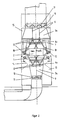
- FIGS. 1 and 2 The invention is described below using a typical exemplary embodiment and explained in greater detail by FIGS. 1 and 2.
- the extruded profile (2) is placed on a transport device, advantageously a roller conveyor (1).
- a roller conveyor (1) that provided in Figures 1 and 2 by the envelope of the maximum Extruded profile cross section is shown, guided by the device.
- Roller conveyor can also be ladder-like sliding blocks made of a suitable material, e.g. B. graphite can be used.
- the lower nozzle box can adjusted with setting aids not shown in the figures according to the roller conveyor be, which can be adapted in the usual way to the outlet height of the profile.
- This Adjustment is indicated in Figure 1 with the double arrows (4).
- the upper nozzle box has one also indicated in FIG. 1 only by double arrows (5) Schnellhub liked, z. B. advantageous a quick raise accordingly synchronized hydraulic cylinder. These are also not shown in the figure, as such Fast lifting devices from other technical applications are well known.
- the nozzle boxes for air cooling (3o) and (3u) have horizontal slotted nozzle ribs (6o) and (6u).
- the upper nozzle ribs (6o) are approximately in the area of the rollers or webs Transport device and the lower nozzle ribs (6u) arranged between them.
- the upper nozzle box (3o) with the on both sides of the Profiles (2) arranged, downwardly directed nozzle arms (7). Through this cooling arms are also provided with slot nozzles (8) on the vertical Blown side faces of the profile.
- the top slot nozzles (6o), the side slot nozzles (8r) and (8l) and the lower slot nozzles (6u) are arranged opposite each other in such a way that their center planes are as evenly spaced as possible from the adjacent slot nozzle and the slot jets are consequently in the cooling area in which the profile (2) is located, do not penetrate. In this way it is achieved that all slit beams that Apply the extruded profile to be cooled evenly and rinse. In compliance with this boundary condition can be any design or manufacturing arrangement Air jets can be chosen to each other.
- the air duct is open to adapt the air cooling effect to the respective extruded profile the inflow side to the nozzles divided into sections parallel to the pressing direction.
- This Sections are formed by the partition plates (9). These dividers sit down in the Connection piece (10) and divide this into fields, each in one Throttle device is installed.
- An advantageous embodiment of such Throttle device are e.g. B. oppositely adjustable flaps (11). With the help of this Throttling devices can now be the blow-out speed of the louvre nozzles in one wide range of the mass and wall thickness distribution of the extruded profile given situation.
- Water pipes (12) are provided for water cooling and run in the pressing direction.
- a cross section of the device according to the invention are each two water pipes Above and below and a water pipe is provided on each side of the extruded profile.
- the number of Above or below the profile and the laterally arranged tubes adapted accordingly.
- These tubes are expediently designed as double tubes.
- These double pipes can as shown in Figure 2, by arranging two rectangular tubes side by side be formed.
- These pipes are equipped with nozzles - expediently flat jet nozzles - equipped.
- the nozzles are arranged so that their spray patterns, as in the cross section of the Device shown in Figure 2, overlap in such a way that a uniform Water exposure takes place over the circumference of the extruded profile. By switching off One of the two double pipes can reduce the water exposure. Another The possibility of reducing the overall water pressure density is through the Possibility of changing the pump pressure by throttling or changing the speed Given pump.
- the nozzles are in the water spray pipes according to the division of the Air jets arranged. This division depends on the minimum pressing speed. she is chosen such that over the pitch length, that is, between the application of two Nozzles, no reheating in the extruded profile due to heat conduction from the material core can take place, which is not permitted for metallurgical reasons.
- the lower air box is integrated in a water collecting container (13).
- This water collector can expediently be equipped with flaps (14) which are too intensive when air-cooled Exclude blowing of the water surface and at the same time an essentially unhindered Allow cooling air to flow out.
- the upper nozzle system is provided with a protective box (15) that is in operation lowered as water cooling and raised when operating as air cooling. So it's with the device according to the invention possible, without any noteworthy changes, which also can still be done automatically, work with both air and water and the entire cooling range from moderate air cooling to intensive air cooling up to to cover high-intensity water cooling.
Abstract
Description
Die Erfindung betrifft eine Vorrichtung zur Abkühlung von Strangpreßprofilen
gemäß dem Oberbegrif des Patentanspruchs 1.The invention relates to a device for cooling extruded profiles
according to the preamble of
Strangpreßprofile müssen nach Verlassen der Preßmatrize abgekühlt werden. Bei Profilen aus Leichtmetallegierungen ist dies aus materialtechnischen Gründen erforderlich, um beim fertig abgekühlten Strangpreßprofil die gewünschten Festigkeitswerte und metallurgischen Eigenschaften zu erreichen. Bei AIMgSi-Legierungen sind die erforderlichen Abkühlgeschwindigkeiten bei größeren Wandstärken nur mit intensiver Wasserbeaufschlagung der Profiloberfläche erreichbar. Bei geringeren Wandstärken ist jedoch bei Wasserabkühlung die Abschreckwirkung so stark, daß beim fertig abgekühlten Profil ein Verzug auftritt, der, wenn überhaupt, nur durch aufwendige Richtmaßnahmen und starke Dehnung des Profils beim Strecken wieder behoben werden kann. Das starke Dehnen beim Strecken ist mit einer nachteiligen Veränderung der metallurgischen Eigenschaften verbunden.Extruded profiles must be cooled after leaving the press die. With profiles from Light metal alloys, this is necessary for material reasons to finish cooled extruded profile the desired strength values and metallurgical To achieve properties. With AIMgSi alloys, the required Cooling speeds with larger wall thicknesses only with intensive exposure to water accessible on the profile surface. With smaller wall thicknesses, however, is with water cooling the quenching effect is so strong that a distortion occurs when the profile has cooled down, if at all, only through elaborate guidelines and strong stretching of the profile when Routes can be fixed again. The strong stretching when stretching is one adverse change in metallurgical properties.
Aus der EP 0 541 630 ist eine Vorrichtung zur Abkühlung von Strangpreßprofilen bekannt, bei der lediglich oberhalb und unterhalb des Profils Luftschlitzdüsen angeordnet sind. Diese Vorrichtung hat den Nachteil, daß dann, wenn die Strangpreßprofile mit größerer Bauhöhe extrudiert werden, die Seitenflächen nicht hinreichend stark beaufschlagt werden und folglich bei derartigen Profilen die Abkühlung über dem Umfang nicht gleichmäßig erfolgt. Nach der Lehre des vorgenannten Patents kann der Wärmeübergang über der Breite des Profils mit im Düsenkörper befindlichen Verstellorganen verändert werden. Dies ist insofern nachteilig, daß diese Verstellorgane in einem relativ großen Strömungsquerschnitt, nämlich dem Zuströmquerschnitt zu den Düsenrippen, angeordnet sind und folglich der freie Durchströmungsquerschnitt auf einen vergleichsweise sehr geringen Querschnitt reduziert werden muß, um überhaupt nennenswerte Veränderungen im Wärmeübergang zu erzielen. A device for cooling extruded profiles is known from EP 0 541 630, at which are only arranged above and below the profile louvre nozzles. This The device has the disadvantage that if the extruded profiles have a greater overall height are extruded, the side surfaces are not subjected to sufficient stress and consequently with such profiles, the cooling is not uniform over the circumference. After Teaching of the aforementioned patent, the heat transfer across the width of the profile with in Adjusting elements located nozzle body can be changed. This is disadvantageous in that these adjusting elements in a relatively large flow cross-section, namely the Inflow cross-section to the nozzle ribs, are arranged and consequently the free one Flow cross section reduced to a comparatively very small cross section must be in order to achieve any significant changes in the heat transfer.
Außerdem ist die Verstelleinrichtung nach der Lehre des vorgenannten Patents relativ aufwendig, da sie sich über die gesamte Fläche des Düsenfeldes erstrecken muß. Ebenfalls nach der Lehre dieses Patents sind in den Luftdüsen Wasserdüsen angeordnet. Diese Wasserdüsen können jedoch nur sinnvoll betrieben werden, wenn zugleich die Luftbeblasung aktiviert ist. Dies hat den großen Nachteil, daß ein hoher Luftvolumenstrom mit Wasser beladen wird und folglich erhebliche Aufwendungen notwendig sind, um die in dem Luftstrom enthaltenen Wassertröpfchen wieder aus demselben abzuscheiden.In addition, the adjustment device according to the teaching of the aforementioned patent is relative expensive, since it must extend over the entire area of the nozzle field. Also after According to the teaching of this patent, water nozzles are arranged in the air nozzles. These water jets can only be operated sensibly if air blowing is activated at the same time. This has the major disadvantage that a high air volume flow is loaded with water and consequently significant expenses are necessary to those contained in the airflow To separate water droplets from the same.
Ein weiterer Nachteil ist, daß die Wasserdüsen nur mit relativ kleinen Wasserbeaufschlagungsdichten betrieben werden können, da ansonsten die Luftströmung nicht mehr die erforderliche Vergleichmäßigung der Wasserbeaufschlagung bewirken kann. Zum Abkühlen von Strangpreßprofilen größerer Wandstärken sind aber Wasserbeaufschlagungsdichten von 500 1/(m2min) bis 1000 l/(m2/min) erforderlich. Dies sind Werte, die mit der bekannten Vorrichtung bei weitem nicht erreicht werden können. Ein sehr entscheidender weiterer Nachteil ist noch, daß die Wasserdüsen nach der Lehre dieses Patents parallel zu den Schlitzdüsen angeordnet sind. Es kann also immer nur eine quer zur Strangpreßrichtung verlaufende Düsenreihe als Ganzes abgeschaltet oder im Druck geändert werden. Zu der erforderlichen Anpassung der Kühlwirkung an die Massen- und Wandstärkenverteilung im Profil ist eine solche Verstellung nicht geeignet.Another disadvantage is that the water nozzles can only be operated with relatively low water pressurization densities, since otherwise the air flow can no longer bring about the required equalization of the water pressurization. For cooling extruded profiles with larger wall thicknesses, however, water pressures of 500 1 / (m 2 min) to 1000 l / (m 2 / min) are required. These are values which by far cannot be achieved with the known device. A very decisive further disadvantage is that the water nozzles are arranged parallel to the slot nozzles according to the teaching of this patent. Thus, only one row of nozzles running transversely to the extrusion direction can be switched off as a whole or the pressure can be changed. Such an adjustment is not suitable for the required adaptation of the cooling effect to the mass and wall thickness distribution in the profile.
Aus der DE-U-88 10 085 ist eine Sprühwasser-Abschreckvorrichtung für Strangpreßprofile
bekannt, wie sie im Oberbegriff des Patentanspruchs 1 beschrieben wird. Die Abkühlung
des Strangpreßprofils erfolgt hier lediglich durch ein Besprühen mit Wasser in einem
Sprühtunnel, während über schwenkbar angeordnete Luftdüsen am Eintritt und am Austritt
der Vorrichtung Luftvorhänge gebildet werden, welche ein Besprühen der Strangpreßprofile
außerhalb des Sprühtunnels verhindern (siehe Seite 7, 2. Abschnitt).DE-U-88 10 085 is a spray water quenching device for extruded profiles
known as described in the preamble of
Bei dieser Vorrichtung stellt es sich als nachteilig heraus, daß eine Kühlung der Strangpreßprofile lediglich durch Luft nicht möglich ist, so daß auch hier bei geringen Wandstärken durch Wasserabkühlung eine zu starke Abschreckwirkung und damit ein Profilverzug eintreten kann. Außerdem ist die zur Verfügungstellung eines Sprühtunnels aufwendig.In this device it turns out to be disadvantageous that cooling of the extruded profiles only by air is not possible, so that even with thin walls due to water cooling, a too strong quenching effect and thus a distortion of the profile can occur. In addition, the provision of a spray tunnel is complex.
Die EP-A- 0 578 607 beschreibt eine Abkühlung von Profilen mit Wasser- und Luftstrahlen, wobei die Wasserstrahlen aus der Düse 28 austreten, während die Luftstrahlen durch Luftspalte 39, 41 auf die Düsenaustrittsöffnungen 38 gerichtet werden. Die Luftdüsenöffnungen bilden mit den Wasserdüsen eine Funktionseinheit, was bedeutet, daß die Wasser- düse nur funktionsgerecht arbeitet, wenn auch die Luftdüsen betrieben werden.EP-A-0 578 607 describes cooling of profiles with water and air jets, the jets of water emerge from the nozzle 28 while the jets of air be directed through air gaps 39, 41 to the nozzle outlet openings 38. The air nozzle openings form a functional unit with the water nozzles, which means that the The water nozzle only works properly if the air nozzles are also operated.
Mit einer Vorrichtung gemäß der EP-A- 0 578 607 kann deshalb nicht der gesamte Kühlbereich von mäßiger Luftkühlung bis zu intensiver Luftkühlung und dann von mäßiger Wasserkühlung bis zu honchintensiver Wasserkühlung abgedeckt werden.A device according to EP-A-0 578 607 cannot therefore cover the entire cooling area from moderate air cooling to intense air cooling and then from moderate Water cooling up to honey-intensive water cooling can be covered.
Es ist die Aufgabe der vorliegenden Erfindung, diese vorgenannten Nachteile zu vermeiden.
Diese Aufgabe wird durch die kennzeichnenden Merkmale des Patentanspruchs 1 gelöst. Die
Unteransprüche definieren bevorzugte Ausführungsformen der Erfindung.It is the object of the present invention to avoid these disadvantages mentioned above.
This object is achieved by the characterizing features of
Insbesondere wird mit der vorliegenden Erfindung eine Vorrichtung zur Abkühlung von Strangpreßprofilen vorgeschlagen, die besonders für Strangpreßprofile aus Leichtmetallegierungen geeignet ist und die sowohl für geringe als auch große Profilwandstärken die erforderlichen hohen Abkühlgeschwindigkeiten ermöglicht, indem Profile geringerer Wandstärke nur mit Luft und Profile mit größerer Wandstärke nur mit Wasser gekühlt werden, wobei aber trotzdem ein Verbiegen oder Verziehen der Profile beim Abkühlen weitestgehend ausgeschlossen wird, da sich sowohl die Luftkühlung als auch die Wasserkühlung der Wandstärken- und Massenverteilung des Profils anpassen lassen. In particular, the present invention provides a device for cooling Extruded profiles proposed that are made especially for extruded profiles Light metal alloys is suitable for both small and large Profile wall thicknesses enables the required high cooling speeds by adding profiles lower wall thickness only with air and profiles with greater wall thickness only with water be cooled, but still bending or warping the profiles when cooling is largely excluded, since both air cooling and water cooling have the wall thickness and mass distribution of the profile adjusted.
Ein großer Vorteil im Vergleich zu anderen Vorrichtungen zum Kühlen von Strangpreßprofilen ist noch, daß die neue Vorrichtung den gesamten Bereich des Wärmeübergangs von der Luftkühlung bis zur schroffen Wasserkühlung überdeckt. Diesem Bereich entspricht für Strangpreßprofile aus Leichtmetallegierungen für den metallurgisch wichtigen Temperaturbereich von ca. 500 °C bis ca. 250 °C ein Umfang des mittleren Wärmeübergangskoeffizienten von ca. 100 W/(m2K) bis ca. 6000 W/(m2K), also ein Bereich von etwa 1:60. Dabei wird im Bereich von 100 W/(m2K) bis ca. 300 W/(m2K) mit Luft und darüber mit Wasser gekühlt. Da in dem vorgenannten Temperaturbereich bei Leichtmetallegierungen die Wasserkühlung oberhalb der sogenannten Leidenfrost-Temperatur stattfindet, ist der Wärmeübergang im wesentlichen von der Wasserbeaufschlagungsdichte abhängig. Die Vorrichtung nach der Erfindung zeichnet sich also dadurch aus, daß die Wasserbeaufschlagungsdichte in dem erforderlichen großen Umfang verändert werden kann und dies ohne die Gleichmäßigkeit der Wasserbeaufschlagung nachteilig zu verändern.A great advantage compared to other devices for cooling extruded profiles is that the new device covers the entire range of heat transfer from air cooling to rugged water cooling. For extruded profiles made of light metal alloys for the metallurgically important temperature range from approx. 500 ° C to approx. 250 ° C, this range corresponds to a range of the average heat transfer coefficient of approx. 100 W / (m 2 K) to approx. 6000 W / (m 2 K) ), a range of around 1:60. It is cooled in the range from 100 W / (m 2 K) to approx. 300 W / (m 2 K) with air and above that with water. Since the water cooling takes place above the so-called Leidenfrost temperature in the above-mentioned temperature range in light metal alloys, the heat transfer essentially depends on the density of water. The device according to the invention is thus characterized in that the water loading density can be changed to the required large extent and this without disadvantageously changing the uniformity of the water loading.
Die Erfindung wird im folgenden anhand eines typischen Ausführungsbeispieles beschrieben und durch die Figuren 1 und 2 näher erläutert.The invention is described below using a typical exemplary embodiment and explained in greater detail by FIGS. 1 and 2.
Es zeigen
Figur 1- eine Längsansicht und
Figur 2- einen Querschnitt der erfindungsgemäßen Vorrichtung.
- Figure 1
- a longitudinal view and
- Figure 2
- a cross section of the device according to the invention.
In den Figuren ist nur eine Sektion der Vorrichtung dargestellt. Wenn die mit der Vorrichtung zu bewältigende Kühlaufgabe dies erfordert, so wird eine entsprechende Anzahl derartiger Sektionen hintereinander angeordnet, wobei in der Regel nur die erste Sektion, wie in den Figuren dargestellt, sowohl als Luftkühlsektion als auch als Wasserkühlsektion betrieben werden kann.Only one section of the device is shown in the figures. If the with the device cooling task to be managed requires a corresponding number of such Sections arranged one behind the other, usually only the first section, as in the Figures shown, operated both as an air cooling section and as a water cooling section can.
Auf einer Transporteinrichtung, vorteilhaft einem Rollengang (1), wird das Strangpreßprofil (2) das in den Figuren 1 und 2 durch die Einhüllende des maximal vorgesehenen Strangpreßprofilquerschnittes dargestellt ist, durch die Vorrichtung geführt. Statt des Rollenganges können auch leiterartig angeordnete Gleitsteine aus einem geeigneten Material, z. B. Graphit, verwendet werden. Oberhalb und unterhalb des Rollenganges ist je ein oberer Düsenkasten (3o) und ein unterer Düsenkasten (3u) angeordnet. Der untere Düsenkasten kann mit in den Figuren nicht dargestellten Einstellhilfen entsprechend dem Rollengang eingestellt werden, der in üblicher Weise an die Auslaufhöhe des Profils angepaßt werden kann. Diese Verstellmöglichkeit ist in Figur 1 mit den Doppelpfeilen (4) angedeutet. Der obere Düsenkasten verfügt über eine in der Figur 1 ebenfalls nur durch Doppelpfeile (5) angedeutete Schnellhubeinrichtung, z. B. vorteilhaft eine Schnellanhebung mit Hilfe entsprechend synchronisierter Hydraulikzylinder. Diese sind ebenfalls in der Figur nicht dargestellt, da solche Schnellhubeinrichtungen aus anderen technischen Anwendungen hinreichend bekannt sind.The extruded profile (2) is placed on a transport device, advantageously a roller conveyor (1). that provided in Figures 1 and 2 by the envelope of the maximum Extruded profile cross section is shown, guided by the device. Instead of Roller conveyor can also be ladder-like sliding blocks made of a suitable material, e.g. B. graphite can be used. There is an upper one above and one below the roller table Nozzle box (3o) and a lower nozzle box (3u) arranged. The lower nozzle box can adjusted with setting aids not shown in the figures according to the roller conveyor be, which can be adapted in the usual way to the outlet height of the profile. This Adjustment is indicated in Figure 1 with the double arrows (4). The upper nozzle box has one also indicated in FIG. 1 only by double arrows (5) Schnellhubeinrichtung, z. B. advantageous a quick raise accordingly synchronized hydraulic cylinder. These are also not shown in the figure, as such Fast lifting devices from other technical applications are well known.
Die Düsenkästen für Luftkühlung (3o) und (3u) tragen horizontale Schlitzdüsenrippen (6o) und (6u). Dabei sind die oberen Düsenrippen (6o) etwa im Bereich der Rollen oder Stege der Transporteinrichtung und die unteren Düsenrippen (6u) dazwischen angeordnet. Zusätzlich zu den Schlitzdüsenrippen (6o) ist der obere Düsenkasten (3o) noch mit den auf beiden Seiten des Profils (2) angeordneten, nach unten gerichteten Düsenarmen (7) ausgestattet. Durch diese ebenfalls mit Schlitzdüsen (8) versehenen Düsenarme wird Kühlluft auf die vertikalen Seitenflächen des Profils geblasen. Die oberen Schlitzdüsen (6o), die seitlichen Schlitzdüsen (8r) und (8l) sowie die unteren Schlitzdüsen (6u) sind derart einander gegenüber angeordnet, daß ihre Mittelebenen möglichst gleichen Abstand zur jeweils benachbarten Schlitzdüse haben und sich die Schlitzstrahlen folglich im Kühlbereich, in welchem sich das Profil (2) befindet, nicht durchdringen. Auf diese Weise wird nämlich erreicht, daß alle Schlitzstrahlen das abzukühlende Strangpreßprofil gleichmäßig beaufschlagen und umspülen. Unter Einhaltung dieser Randbedingung kann jede konstruktions- oder fertigungstechnische Anordnung der Luftdüsen zueinander gewählt werden.The nozzle boxes for air cooling (3o) and (3u) have horizontal slotted nozzle ribs (6o) and (6u). The upper nozzle ribs (6o) are approximately in the area of the rollers or webs Transport device and the lower nozzle ribs (6u) arranged between them. In addition to the slot nozzle ribs (6o) is the upper nozzle box (3o) with the on both sides of the Profiles (2) arranged, downwardly directed nozzle arms (7). Through this cooling arms are also provided with slot nozzles (8) on the vertical Blown side faces of the profile. The top slot nozzles (6o), the side slot nozzles (8r) and (8l) and the lower slot nozzles (6u) are arranged opposite each other in such a way that their center planes are as evenly spaced as possible from the adjacent slot nozzle and the slot jets are consequently in the cooling area in which the profile (2) is located, do not penetrate. In this way it is achieved that all slit beams that Apply the extruded profile to be cooled evenly and rinse. In compliance with this boundary condition can be any design or manufacturing arrangement Air jets can be chosen to each other.
Zur Anpassung der Luftkühlwirkung an das jeweilige Strangpreßprofil ist die Luftführung auf der Zuströmseite zu den Düsen in Abschnitte parallel zur Preßrichtung unterteilt. Diese Abschnitte werden durch die Trennbleche (9) gebildet. Diese Trennbleche setzen sich bis in den Anschlußstutzen (10) fort und unterteilen diesen in Felder, in welche jeweils eine Drosseleinrichtung eingebaut ist. Eine vorteilhafte Ausführungsform einer solchen Drosseleinrichtung sind z. B. gegenläufig verstellbare Klappen (11). Mit Hilfe dieser Drosseleinrichtungen kann nunmehr die Ausblasgeschwindigkeit der Luftschlitzdüsen in einem weiten Bereich der durch Massen- bzw. Wandstärkenverteilung des Strangpreßprofils vorgegebenen Situation angepaßt werden. The air duct is open to adapt the air cooling effect to the respective extruded profile the inflow side to the nozzles divided into sections parallel to the pressing direction. This Sections are formed by the partition plates (9). These dividers sit down in the Connection piece (10) and divide this into fields, each in one Throttle device is installed. An advantageous embodiment of such Throttle device are e.g. B. oppositely adjustable flaps (11). With the help of this Throttling devices can now be the blow-out speed of the louvre nozzles in one wide range of the mass and wall thickness distribution of the extruded profile given situation.
Für die Wasserkühlung sind Wasserrohre (12) vorgesehen, die in Preßrichtung verlaufen. In Figur 2, einem Querschnitt der Vorrichtung nach der Erfindung, sind jeweils zwei Wasserrohre oberhalb und unterhalb und je ein Wasserrohr auf jeder Seite des Strangpreßprofils vorgesehen. Bei Abkühlvorrichtungen für breitere und/oder höhere Strangpreßprofile wird die Anzahl der über- bzw. unterhalb des Profils sowie der seitlich angeordneten Rohre entsprechend angepaßt. Zweckmäßiger Weise sind diese Rohre als Doppelrohre ausgeführt. Diese Doppelrohre können, wie in Figur 2 dargestellt, durch die Anordnung von zwei Rechteckrohren nebeneinander gebildet werden. Diese Rohre sind mit Düsen - zweckmäßiger Weise Flachstrahldüsen - ausgerüstet. Die Düsen sind so angeordnet, daß deren Spritzbilder, wie im Querschnitt der Vorrichtung Figur 2 dargestellt, sich derart überdecken, daß eine gleichmäßige Wasserbeaufschlagung über dem Umfang des Strangpreßprofils stattfindet.. Durch Abschalten eines der beiden Dopppelrohre kann die Wasserbeaufschlagung verringert werden. Eine weitere Möglichkeit, die Wasserbeaufschlagungsdichte insgesamt zu verringern, ist durch die Möglichkeit der Veränderung des Pumpendruckes durch Drosselung oder Drehzahländerung der Pumpe gegeben. Die Düsen sind in den Wasserspritzrohren entsprechend der Teilung der Luftdüsen angeordnet. Diese Teilung ist von der minimalen Preßgeschwindigkeit abhängig. Sie wird derart gewählt, daß über der Teilungslänge, also zwischen der Beaufschlagung von zwei Düsen, keine Rückerwärmung im Strangpreßprofil durch Wärmeleitung aus dem Materialkern stattfinden kann, die aus metallurgischen Gründen nicht zulässig ist.Water pipes (12) are provided for water cooling and run in the pressing direction. In Figure 2, a cross section of the device according to the invention, are each two water pipes Above and below and a water pipe is provided on each side of the extruded profile. In the case of cooling devices for wider and / or higher extruded profiles, the number of Above or below the profile and the laterally arranged tubes adapted accordingly. These tubes are expediently designed as double tubes. These double pipes can as shown in Figure 2, by arranging two rectangular tubes side by side be formed. These pipes are equipped with nozzles - expediently flat jet nozzles - equipped. The nozzles are arranged so that their spray patterns, as in the cross section of the Device shown in Figure 2, overlap in such a way that a uniform Water exposure takes place over the circumference of the extruded profile. By switching off One of the two double pipes can reduce the water exposure. Another The possibility of reducing the overall water pressure density is through the Possibility of changing the pump pressure by throttling or changing the speed Given pump. The nozzles are in the water spray pipes according to the division of the Air jets arranged. This division depends on the minimum pressing speed. she is chosen such that over the pitch length, that is, between the application of two Nozzles, no reheating in the extruded profile due to heat conduction from the material core can take place, which is not permitted for metallurgical reasons.
Da die Kühlwirkung mit Wasser erheblich höher ist als mit Luft, ist es zweckmäßig, in einer Sektion einer Luftkühlung mindestens zwei Sektionen einer Wasserkühlung vorzusehen. Dies ist auf einfache Weise dadurch möglich, daß die längsverlaufenden, mit Düsen bestockten Wasserrohre an den entsprechenden Stellen der Vorrichtung getrennt werden und jeweils eine separate Zuführung möglichst von einer separaten Pumpe erhalten. Auf diese Weise kann die Wasserbeaufschlagung auch über der Länge der Profile in der Kühleinrichtung verändert werden. Es ist so z. B. möglich, im ersten Bereich der Abkühlung, wo das Profil besonders empfindlich ist, da es sich bei den entsprechenden Temperaturen noch plastisch verformt, schwächer zu kühlen und eine stärkere Kühlung erst dann vorzunehmen, wenn, bedingt durch den Fortschritt der Abkühlung, der Elastizitätsmodul des Materials sich wieder dem Elastizitätsmodul bei Umgebungstemperatur angenähert hat und eine Verformung durch ungleichmäßige Kühlung elastisch erfolgt, also nach Temperaturausgleich im Profil wieder verschwindet. Since the cooling effect with water is considerably higher than with air, it is advisable to use one Air cooling section to provide at least two sections of water cooling. This is possible in a simple manner in that the longitudinal, stocked with nozzles Water pipes are separated at the corresponding points in the device and one each Obtain separate feed if possible from a separate pump. In this way, the Water exposure also changed over the length of the profiles in the cooling device become. It is so. B. possible in the first area of cooling, where the profile is special is sensitive because it deforms plastically at the appropriate temperatures, to cool less and only to carry out more cooling if, due to the progress of cooling, the modulus of elasticity of the material again the modulus of elasticity has approached at ambient temperature and has been deformed by uneven cooling occurs elastically, i.e. after temperature compensation in the profile again disappears.
Um den Betrieb sowohl mit Wasser als auch mit Luft zu ermöglichen, ist der untere Luftkasten in einen Wasserauffangbehälter (13) integriert. Dieser Wasserauffangbehälter kann zweckmäßiger Weise mit Klappen (14) ausgerüstet sein, die bei Luftkühlung eine zu intensive Beblasung der Wasseroberfläche ausschließen und zugleich ein im wesentlichen ungehindertes Abströmen der Kühlluft gestatten. Zur Vermeidung von Spritzwasser im oberen Bereich der Profilkühlung ist das obere Düsensystem mit einem Schutzkasten (15) versehen, der bei Betrieb als Wasserkühlung abgesenkt und bei Betrieb als Luftkühlung angehoben wird. Es ist also mit der Vorrichtung nach der Erfindung möglich, ohne nennenswerte Umstellungen, die zudem noch automatisch erfolgen können, sowohl mit Luft als auch mit Wasser zu arbeiten und den gesamten Kühlbereich von mäßiger Luftkühlung über intensive Luftkühlung bis zu hochintensiver Wasserkühlung zu überdecken.To enable operation with both water and air, the lower air box is integrated in a water collecting container (13). This water collector can expediently be equipped with flaps (14) which are too intensive when air-cooled Exclude blowing of the water surface and at the same time an essentially unhindered Allow cooling air to flow out. To avoid splashing water in the upper area of the Profile cooling, the upper nozzle system is provided with a protective box (15) that is in operation lowered as water cooling and raised when operating as air cooling. So it's with the device according to the invention possible, without any noteworthy changes, which also can still be done automatically, work with both air and water and the entire cooling range from moderate air cooling to intensive air cooling up to to cover high-intensity water cooling.
Claims (12)
- A device for cooling extruded profiles comprisingcharacterized in thatslotted air nozzles (6u, 6o) arranged above and below the extruded profile (2) moving on an exit runway (1) and oriented transversely to the direction of movement of the profile, andwater application nozzles for impinging the extruded profile (2) with water, separate from said air nozzles (6u, 6o),said water application nozzles (12) are arranged in tubes (12) extending in the direction of movement of said profiles such that said impingement portions of said individual water application nozzles (12) supplement each other for a homogenous impingement of said extruded profile (2), thatsaid air nozzles (6u, 6o) are air slot nozzles ensuring cooling of said profiles over substantially the full length of the device and thatthe device is configured so that cooling occurs either only by means of said air slot nozzles or only by means of said water application nozzles (12).
- The device as set forth in claim 1, characterized in that the tubes are arranged above, below and an the side of the extruded profile.
- The device as set forth in one of claims 1 or 2, characterized in that means are provided for adapting air application and/or water application to the cooling rate of the profile (2) required in each case, the means being preferably automatically controlled.
- The device as set forth in any of the claims 1 to 3, characterized in that the upper air slot nozzles (8l, 8r) are also arranged laterally an both sides of the extruded profile.
- The device according to one or several of the claims 1 to 4, characterized in that the supply to the air slot nozzles (6u, 6o) is divided in sections extending in the longitudinal direction of the device and these zones (9) continue up to an air supply port (10) provided in the region divided by said zones with flow reducing means (11) for adjusting the strength of the air flow into each of the zoned sections.
- The device as set forth in claim 5, characterized in that an upper blowing header (30) including the upper air slot nozzles (6o) is sectioned into at least three sections and a lower blowing header (3u) including the lower air slot nozzles (6u) is sectioned into at least two sections, particularly the sectioning of the upper blowing header (30) permitting separate adjustment of the blowing strength of the side located slot nozzles (8l, 8r).
- The device as set forth in any of the claims 1 to 6, characterized in that the water tubes (12) are devised as double tubes.
- The device as set forth in any of the claims 1 to 7, characterized in that the water tubes (12) extending in the longitudinal direction of the device and fitted with spray nozzles may be individually switched ON/OFF.
- The device as set forth in any of the claims 1 to 8, characterized in that several sections of such a device are arranged successively, one or more section(s) being equipped with both air slot nozzles and water application nozzles and one or more section(s) being exclusively equipped with air slot nozzles.
- The device as set forth in any of the claims 1 to 9, characterized in that an air cooling section of the device is sectioned into at least two water cooling sections, the individual water cooling sections being provided with a water feed at a separately adjustable supply pressure and each comprising water tubes (12), which are separately switchable, oriented in the longitudinal direction of the device and provided with spray nozzles.
- The device as set forth in any of the claims 1 to 8, characterized in that flat spray nozzles are employed as water application nozzles.
- The device as set forth in any of the claims 1 to 9, characterized in that its lower portion is integrated into a water catchment tank (13) provided with exit flow valves (14) to be opened during an air cooling Operation, further characterized in that its upper portion is surrounded by a shroud (15) for splash protection which may be raised during an air cooling Operation to prevent obstruction of the exit flow of cooling air.
Applications Claiming Priority (3)
| Application Number | Priority Date | Filing Date | Title |
|---|---|---|---|
| DE19649073 | 1996-11-28 | ||
| DE19649073A DE19649073C2 (en) | 1996-11-28 | 1996-11-28 | Device for cooling extruded profiles |
| PCT/EP1997/006605 WO1998023397A2 (en) | 1996-11-28 | 1997-11-27 | Device for cooling extruded profiles |
Publications (2)
| Publication Number | Publication Date |
|---|---|
| EP0942792A2 EP0942792A2 (en) | 1999-09-22 |
| EP0942792B1 true EP0942792B1 (en) | 2001-05-23 |
Family
ID=7812891
Family Applications (1)
| Application Number | Title | Priority Date | Filing Date |
|---|---|---|---|
| EP97954666A Expired - Lifetime EP0942792B1 (en) | 1996-11-28 | 1997-11-27 | Device for cooling extruded profiles |
Country Status (8)
| Country | Link |
|---|---|
| US (1) | US6216485B1 (en) |
| EP (1) | EP0942792B1 (en) |
| JP (1) | JP4319254B2 (en) |
| AT (1) | ATE201339T1 (en) |
| DE (2) | DE19649073C2 (en) |
| ES (1) | ES2158617T3 (en) |
| NO (1) | NO310677B1 (en) |
| WO (1) | WO1998023397A2 (en) |
Cited By (2)
| Publication number | Priority date | Publication date | Assignee | Title |
|---|---|---|---|---|
| DE102016102093B3 (en) * | 2016-02-05 | 2017-06-14 | Bwg Bergwerk- Und Walzwerk-Maschinenbau Gmbh | Continuous cooling device and method for cooling a metal strip |
| DE102021212523A1 (en) | 2021-05-31 | 2022-12-01 | Sms Group Gmbh | Forced air cooling for cooling long steel products |
Families Citing this family (14)
| Publication number | Priority date | Publication date | Assignee | Title |
|---|---|---|---|---|
| NO20011301L (en) * | 2001-03-14 | 2002-09-16 | Norsk Hydro As | Method and equipment for cooling profiles after extrusion |
| JP2002275603A (en) * | 2001-03-16 | 2002-09-25 | Kobe Steel Ltd | Process and cooling device for press quenching of heat- treated aluminum alloy extruded material |
| MXPA03008628A (en) | 2001-03-22 | 2006-03-15 | Univ Maryland | Sensor probe for measuring temperature and liquid volumetric fraction of a liquid droplet laden hot gas and method of using same. |
| DE10207584A1 (en) * | 2002-02-22 | 2003-09-11 | Vits Maschb Gmbh I Ins | Process for cooling metal strips or plates and cooling device |
| DE102006033007B3 (en) * | 2006-07-17 | 2007-08-30 | Unterschütz Sondermaschinenbau GmbH | Air-cooling equipment for profile leaving extrusion press, includes modular side nozzles with oval outlets set at different heights to suit extrusion dimensions |
| DE102007032919B3 (en) * | 2007-07-12 | 2008-10-23 | Unterschütz, Uwe, Dipl.-Ing. | Extruded material water-cooling device, uses roller conveyor in cooling system to increase or reduce height compensation of cooling system |
| DE102007032917B3 (en) * | 2007-07-12 | 2008-08-28 | Unterschütz, Uwe, Dipl.-Ing. | Pressed strand cooling device, has cooling system with displacement drive i.e. hydraulic drive, designed in manner that cooling system is displaced in direction to press front edge in opposite direction |
| DE102011112560B3 (en) * | 2011-09-08 | 2012-11-08 | Techmag Ag | Plant for the production of cast components and semi-finished products |
| CN102699096A (en) * | 2012-06-01 | 2012-10-03 | 安徽同曦金鹏铝业有限公司 | Aluminum profile cooling device |
| CN104673980B (en) * | 2015-03-18 | 2017-09-26 | 苏州明志科技有限公司 | A kind of quenching unit of aluminum alloy heat processing |
| ITUB20155180A1 (en) * | 2015-11-03 | 2017-05-03 | Presezzi Extrusion S P A | COOLING SYSTEM FOR EXTRUDED PRODUCT EXIT FROM THE EXTRUDER |
| CN109396205B (en) * | 2018-12-17 | 2020-03-27 | 肇庆科达机械制造有限公司 | Aluminum profile extruder and using method thereof |
| IT202000021730A1 (en) * | 2020-09-15 | 2022-03-15 | Danieli Off Mecc | EQUIPMENT FOR THE HEAT TREATMENT OF HIGH TEMPERATURE PRODUCTS, IN PARTICULAR FOR THE CONTROLLED COOLING OF EXTRUDED ALUMINUM PROFILES |
| CN113278774A (en) * | 2021-06-16 | 2021-08-20 | 东台市正祥金属制品有限公司 | Split type lifting quenching device for section steel production |
Family Cites Families (10)
| Publication number | Priority date | Publication date | Assignee | Title |
|---|---|---|---|---|
| DE1583418B2 (en) * | 1967-08-08 | 1972-05-18 | Ukrainskij Nautschno-Issledowatelskij Institut Metallow, Charkow (Sowjetunion) | DEVICE FOR CONTINUOUS SHUTTERING OF RAILS |
| US3997376A (en) * | 1974-06-19 | 1976-12-14 | Midland-Ross Corporation | Spray mist cooling method |
| US4407487A (en) * | 1980-01-15 | 1983-10-04 | Heurtey Metallurgie | Device for cooling metal articles |
| CA1193176A (en) | 1982-07-06 | 1985-09-10 | Robert J. Ackert | Method for the production of improved railway rails by accelerated colling in line with the production rolling mill |
| IT1225174B (en) * | 1988-07-19 | 1990-11-02 | Renzo Righetti | METHOD FOR COOLING CERAMIC MATERIALS, PARTICULARLY CERAMIC TILES IN ROLLER KILNS, AND RELATED PLANT |
| DE8810085U1 (en) * | 1988-08-08 | 1988-10-20 | Elhaus, Friedrich Wilhelm, Dipl.-Ing., 7703 Rielasingen-Worblingen, De | |
| DE4024605A1 (en) * | 1990-08-02 | 1992-02-06 | Wsp Ingenieurgesellschaft Fuer | DEVICE FOR COOLING EXTRUSION PROFILES |
| CH686072A5 (en) | 1992-06-19 | 1995-12-29 | Alusuisse Lonza Services Ag | Spray system for Kuhlen profiles. |
| US5595632A (en) * | 1994-02-01 | 1997-01-21 | James Ross Limited | Shower for paper making machine |
| DE19500019A1 (en) * | 1995-01-03 | 1996-07-04 | Hans Ruediger Dr Ing Hoffmann | Evacuable chamber for cooling metallic materials after heat treatment |
-
1996
- 1996-11-28 DE DE19649073A patent/DE19649073C2/en not_active Expired - Lifetime
-
1997
- 1997-11-27 EP EP97954666A patent/EP0942792B1/en not_active Expired - Lifetime
- 1997-11-27 ES ES97954666T patent/ES2158617T3/en not_active Expired - Lifetime
- 1997-11-27 DE DE59703620T patent/DE59703620D1/en not_active Expired - Lifetime
- 1997-11-27 US US09/308,871 patent/US6216485B1/en not_active Expired - Fee Related
- 1997-11-27 WO PCT/EP1997/006605 patent/WO1998023397A2/en active IP Right Grant
- 1997-11-27 AT AT97954666T patent/ATE201339T1/en not_active IP Right Cessation
- 1997-11-27 JP JP52428398A patent/JP4319254B2/en not_active Expired - Fee Related
-
1999
- 1999-05-27 NO NO19992556A patent/NO310677B1/en not_active IP Right Cessation
Cited By (3)
| Publication number | Priority date | Publication date | Assignee | Title |
|---|---|---|---|---|
| DE102016102093B3 (en) * | 2016-02-05 | 2017-06-14 | Bwg Bergwerk- Und Walzwerk-Maschinenbau Gmbh | Continuous cooling device and method for cooling a metal strip |
| WO2017133867A1 (en) | 2016-02-05 | 2017-08-10 | Bwg Bergwerk- Und Walzwerk-Maschinenbau Gmbh | Continuous flow cooling device and method for cooling a metal strip |
| DE102021212523A1 (en) | 2021-05-31 | 2022-12-01 | Sms Group Gmbh | Forced air cooling for cooling long steel products |
Also Published As
| Publication number | Publication date |
|---|---|
| DE19649073C2 (en) | 2000-12-07 |
| JP2001509738A (en) | 2001-07-24 |
| DE19649073A1 (en) | 1998-06-04 |
| WO1998023397A3 (en) | 1998-10-29 |
| ATE201339T1 (en) | 2001-06-15 |
| NO992556D0 (en) | 1999-05-27 |
| ES2158617T3 (en) | 2001-09-01 |
| DE59703620D1 (en) | 2001-06-28 |
| EP0942792A2 (en) | 1999-09-22 |
| NO992556L (en) | 1999-05-27 |
| JP4319254B2 (en) | 2009-08-26 |
| NO310677B1 (en) | 2001-08-13 |
| US6216485B1 (en) | 2001-04-17 |
| WO1998023397A2 (en) | 1998-06-04 |
Similar Documents
| Publication | Publication Date | Title |
|---|---|---|
| EP0942792B1 (en) | Device for cooling extruded profiles | |
| EP0541630B1 (en) | Device for cooling extruded profiles | |
| DE2614663C3 (en) | Device for treating a workpiece with ultraviolet light | |
| DE4010280A1 (en) | DEVICE FOR BLOWING TWO-SIDED BLOWING OF A TRAIN-SHAPED MATERIAL WITH A TREATMENT GAS | |
| EP0649821A1 (en) | Apparatus for heating or cooling of flat glass sheets or strips | |
| EP3350352B1 (en) | Continuous flow cooling device and method for cooling a metal strip | |
| EP3074150B1 (en) | Method for heat-treating, and quenching device for cooling plate- or web-like sheet metal | |
| DE102017126978A1 (en) | Apparatus and method for tempering workpieces | |
| DE3612720C2 (en) | ||
| DE69833871T2 (en) | DEVICE FOR CURING CURVED GLASS PANES | |
| EP3632640B1 (en) | Treatment plant for a flexible material sheet which can be passed through a treatment furnace, especially a plastic film | |
| EP0907476B1 (en) | Blower nozzle | |
| EP0563509B1 (en) | Air outlet for air treatment installations | |
| DE102006033007B3 (en) | Air-cooling equipment for profile leaving extrusion press, includes modular side nozzles with oval outlets set at different heights to suit extrusion dimensions | |
| EP1218562B1 (en) | Method for heat treatment of metallic slugs | |
| EP0513631A1 (en) | Device for cooling a flat product, in particular a metal strip | |
| DE60002456T2 (en) | HEAT SHIELDS | |
| DE4337342A1 (en) | Device for cooling rolled strips | |
| DE10129000A1 (en) | Firing furnace with cooling zone has motor-driven roller conveyor, distributors, and ventilation fan, | |
| EP3686291B1 (en) | Apparatus and method for cooling metallic sheet | |
| EP0001770B1 (en) | Process and apparatus for cooling billets | |
| DE1596384B2 (en) | METHOD FOR TRANSPORTING A SOFT GLASS PANEL AND DEVICE FOR CARRYING OUT THE METHOD | |
| DE1421784C (en) | Method of transferring heat between a sheet of glass and a gas | |
| DE102022202100A1 (en) | scraper device | |
| DE1596384C3 (en) | Method for transporting a glass pane in which state and device for carrying out the method |
Legal Events
| Date | Code | Title | Description |
|---|---|---|---|
| PUAI | Public reference made under article 153(3) epc to a published international application that has entered the european phase |
Free format text: ORIGINAL CODE: 0009012 |
|
| 17P | Request for examination filed |
Effective date: 19990416 |
|
| AK | Designated contracting states |
Kind code of ref document: A2 Designated state(s): AT BE CH DE ES FR GB IT LI NL SE |
|
| GRAG | Despatch of communication of intention to grant |
Free format text: ORIGINAL CODE: EPIDOS AGRA |
|
| 17Q | First examination report despatched |
Effective date: 20000829 |
|
| GRAG | Despatch of communication of intention to grant |
Free format text: ORIGINAL CODE: EPIDOS AGRA |
|
| GRAH | Despatch of communication of intention to grant a patent |
Free format text: ORIGINAL CODE: EPIDOS IGRA |
|
| GRAH | Despatch of communication of intention to grant a patent |
Free format text: ORIGINAL CODE: EPIDOS IGRA |
|
| GRAA | (expected) grant |
Free format text: ORIGINAL CODE: 0009210 |
|
| AK | Designated contracting states |
Kind code of ref document: B1 Designated state(s): AT BE CH DE ES FR GB IT LI NL SE |
|
| REF | Corresponds to: |
Ref document number: 201339 Country of ref document: AT Date of ref document: 20010615 Kind code of ref document: T |
|
| REG | Reference to a national code |
Ref country code: CH Ref legal event code: NV Representative=s name: RIEDERER HASLER & PARTNER PATENTANWAELTE AG Ref country code: CH Ref legal event code: EP |
|
| GBT | Gb: translation of ep patent filed (gb section 77(6)(a)/1977) |
Effective date: 20010523 |
|
| ITF | It: translation for a ep patent filed |
Owner name: JACOBACCI & PERANI S.P.A. |
|
| REF | Corresponds to: |
Ref document number: 59703620 Country of ref document: DE Date of ref document: 20010628 |
|
| REG | Reference to a national code |
Ref country code: ES Ref legal event code: FG2A Ref document number: 2158617 Country of ref document: ES Kind code of ref document: T3 |
|
| ET | Fr: translation filed | ||
| REG | Reference to a national code |
Ref country code: GB Ref legal event code: IF02 |
|
| PLBQ | Unpublished change to opponent data |
Free format text: ORIGINAL CODE: EPIDOS OPPO |
|
| PLBI | Opposition filed |
Free format text: ORIGINAL CODE: 0009260 |
|
| PLBF | Reply of patent proprietor to notice(s) of opposition |
Free format text: ORIGINAL CODE: EPIDOS OBSO |
|
| 26 | Opposition filed |
Opponent name: SMS EUMUCO GMBH Effective date: 20020221 |
|
| NLR1 | Nl: opposition has been filed with the epo |
Opponent name: SMS EUMUCO GMBH |
|
| PLBF | Reply of patent proprietor to notice(s) of opposition |
Free format text: ORIGINAL CODE: EPIDOS OBSO |
|
| REG | Reference to a national code |
Ref country code: CH Ref legal event code: PUE Owner name: INGENIEURGEMEINSCHAFT WSP PROF. DR.-ING. C.KRAMER |
|
| REG | Reference to a national code |
Ref country code: GB Ref legal event code: 732E |
|
| RAP2 | Party data changed (patent owner data changed or rights of a patent transferred) |
Owner name: KRAMER, CARL, PROF.DR.-ING. |
|
| NLT2 | Nl: modifications (of names), taken from the european patent patent bulletin |
Owner name: KRAMER, CARL, PROF.DR.-ING. |
|
| REG | Reference to a national code |
Ref country code: FR Ref legal event code: TP |
|
| NLS | Nl: assignments of ep-patents |
Owner name: PROF.DR.-ING. C. KRAMER |
|
| PLBO | Opposition rejected |
Free format text: ORIGINAL CODE: EPIDOS REJO |
|
| APBP | Date of receipt of notice of appeal recorded |
Free format text: ORIGINAL CODE: EPIDOSNNOA2O |
|
| APBQ | Date of receipt of statement of grounds of appeal recorded |
Free format text: ORIGINAL CODE: EPIDOSNNOA3O |
|
| REG | Reference to a national code |
Ref country code: ES Ref legal event code: PC2A |
|
| APAA | Appeal reference recorded |
Free format text: ORIGINAL CODE: EPIDOS REFN |
|
| APBU | Appeal procedure closed |
Free format text: ORIGINAL CODE: EPIDOSNNOA9O |
|
| PLBN | Opposition rejected |
Free format text: ORIGINAL CODE: 0009273 |
|
| STAA | Information on the status of an ep patent application or granted ep patent |
Free format text: STATUS: OPPOSITION REJECTED |
|
| 27O | Opposition rejected |
Effective date: 20050223 |
|
| NLR2 | Nl: decision of opposition |
Effective date: 20050223 |
|
| APAH | Appeal reference modified |
Free format text: ORIGINAL CODE: EPIDOSCREFNO |
|
| PGFP | Annual fee paid to national office [announced via postgrant information from national office to epo] |
Ref country code: ES Payment date: 20091123 Year of fee payment: 13 Ref country code: DE Payment date: 20091120 Year of fee payment: 13 Ref country code: CH Payment date: 20091124 Year of fee payment: 13 Ref country code: AT Payment date: 20091113 Year of fee payment: 13 |
|
| PGFP | Annual fee paid to national office [announced via postgrant information from national office to epo] |
Ref country code: NL Payment date: 20091112 Year of fee payment: 13 |
|
| PGFP | Annual fee paid to national office [announced via postgrant information from national office to epo] |
Ref country code: IT Payment date: 20091126 Year of fee payment: 13 Ref country code: GB Payment date: 20091119 Year of fee payment: 13 Ref country code: FR Payment date: 20091201 Year of fee payment: 13 |
|
| PGFP | Annual fee paid to national office [announced via postgrant information from national office to epo] |
Ref country code: BE Payment date: 20091224 Year of fee payment: 13 |
|
| PGFP | Annual fee paid to national office [announced via postgrant information from national office to epo] |
Ref country code: SE Payment date: 20101112 Year of fee payment: 14 |
|
| BERE | Be: lapsed |
Owner name: PROF. DR.-ING. CARL *KRAMER Effective date: 20101130 |
|
| REG | Reference to a national code |
Ref country code: NL Ref legal event code: V1 Effective date: 20110601 |
|
| REG | Reference to a national code |
Ref country code: CH Ref legal event code: PL |
|
| GBPC | Gb: european patent ceased through non-payment of renewal fee |
Effective date: 20101127 |
|
| PG25 | Lapsed in a contracting state [announced via postgrant information from national office to epo] |
Ref country code: CH Free format text: LAPSE BECAUSE OF NON-PAYMENT OF DUE FEES Effective date: 20101130 Ref country code: LI Free format text: LAPSE BECAUSE OF NON-PAYMENT OF DUE FEES Effective date: 20101130 |
|
| REG | Reference to a national code |
Ref country code: DE Ref legal event code: R119 Ref document number: 59703620 Country of ref document: DE Effective date: 20110601 Ref country code: DE Ref legal event code: R119 Ref document number: 59703620 Country of ref document: DE Effective date: 20110531 |
|
| REG | Reference to a national code |
Ref country code: FR Ref legal event code: ST Effective date: 20110801 |
|
| PG25 | Lapsed in a contracting state [announced via postgrant information from national office to epo] |
Ref country code: AT Free format text: LAPSE BECAUSE OF NON-PAYMENT OF DUE FEES Effective date: 20101127 Ref country code: BE Free format text: LAPSE BECAUSE OF NON-PAYMENT OF DUE FEES Effective date: 20101130 Ref country code: NL Free format text: LAPSE BECAUSE OF NON-PAYMENT OF DUE FEES Effective date: 20110601 |
|
| PG25 | Lapsed in a contracting state [announced via postgrant information from national office to epo] |
Ref country code: DE Free format text: LAPSE BECAUSE OF NON-PAYMENT OF DUE FEES Effective date: 20110531 |
|
| PG25 | Lapsed in a contracting state [announced via postgrant information from national office to epo] |
Ref country code: FR Free format text: LAPSE BECAUSE OF NON-PAYMENT OF DUE FEES Effective date: 20101130 |
|
| PG25 | Lapsed in a contracting state [announced via postgrant information from national office to epo] |
Ref country code: GB Free format text: LAPSE BECAUSE OF NON-PAYMENT OF DUE FEES Effective date: 20101127 |
|
| PG25 | Lapsed in a contracting state [announced via postgrant information from national office to epo] |
Ref country code: IT Free format text: LAPSE BECAUSE OF NON-PAYMENT OF DUE FEES Effective date: 20101127 |
|
| REG | Reference to a national code |
Ref country code: ES Ref legal event code: FD2A Effective date: 20120110 |
|
| PG25 | Lapsed in a contracting state [announced via postgrant information from national office to epo] |
Ref country code: ES Free format text: LAPSE BECAUSE OF NON-PAYMENT OF DUE FEES Effective date: 20101128 |
|
| REG | Reference to a national code |
Ref country code: SE Ref legal event code: EUG |
|
| PG25 | Lapsed in a contracting state [announced via postgrant information from national office to epo] |
Ref country code: SE Free format text: LAPSE BECAUSE OF NON-PAYMENT OF DUE FEES Effective date: 20111128 |