EP3631924B1 - Explosionssicheres gehäuse mit druckentlastung - Google Patents
Explosionssicheres gehäuse mit druckentlastung Download PDFInfo
- Publication number
- EP3631924B1 EP3631924B1 EP18726966.7A EP18726966A EP3631924B1 EP 3631924 B1 EP3631924 B1 EP 3631924B1 EP 18726966 A EP18726966 A EP 18726966A EP 3631924 B1 EP3631924 B1 EP 3631924B1
- Authority
- EP
- European Patent Office
- Prior art keywords
- housing
- interior
- pressure relief
- explosion
- arrangement
- Prior art date
- Legal status (The legal status is an assumption and is not a legal conclusion. Google has not performed a legal analysis and makes no representation as to the accuracy of the status listed.)
- Not-in-force
Links
Images

Classifications
-
- H—ELECTRICITY
- H02—GENERATION; CONVERSION OR DISTRIBUTION OF ELECTRIC POWER
- H02B—BOARDS, SUBSTATIONS OR SWITCHING ARRANGEMENTS FOR THE SUPPLY OR DISTRIBUTION OF ELECTRIC POWER
- H02B1/00—Frameworks, boards, panels, desks, casings; Details of substations or switching arrangements
- H02B1/26—Casings; Parts thereof or accessories therefor
- H02B1/28—Casings; Parts thereof or accessories therefor dustproof, splashproof, drip-proof, waterproof or flameproof
-
- H—ELECTRICITY
- H05—ELECTRIC TECHNIQUES NOT OTHERWISE PROVIDED FOR
- H05K—PRINTED CIRCUITS; CASINGS OR CONSTRUCTIONAL DETAILS OF ELECTRIC APPARATUS; MANUFACTURE OF ASSEMBLAGES OF ELECTRICAL COMPONENTS
- H05K5/00—Casings, cabinets or drawers for electric apparatus
- H05K5/02—Details
- H05K5/0217—Mechanical details of casings
Definitions
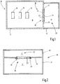
- the subject of the invention is an explosion-proof housing, in particular a housing of protection type Ex-d, according to claim 1.
- Enclosures of protection type Ex-d are often used in potentially explosive areas. Such housings are so robust that they can withstand an ignition of an explosive gas mixture inside the housing and the subsequent increase in pressure.
- the housings are designed in such a way that no flames or glowing particles that act as ignition sources can escape. If there are gaps, they must have a minimum length and must not exceed a maximum width.
- the housing openings are provided with pressure relief devices, which are also referred to as flame protection filters and prevent an explosion ignited in the housing from escaping to the outside and igniting any explosive mixture present in the environment.
- An example of an explosion-proof housing is the DD 261 063 A3 refer to.
- the housing illustrated there has a porous body in its interior, for example made of slag wool, glass wool or metal or ceramic with open pores or gaps. This body should lead to a reduction of the explosion pressure by approx. 90%.
- an explosion-proof housing of the protection type "flameproof enclosure” (Ex-d) is known, in the housing wall of which a porous pressure relief body is provided, through which an explosion pressure built up in the housing can penetrate to the outside.
- a pressure relief body In addition, from the DE 10 2014 116 149 A1 an advantageous structure of a pressure relief body is known. This consists of several wire mesh layers with different orientations and mesh sizes, whereby these layers have been connected to one another by a sintering process. If such housings are arranged in an adverse environment, for example with a dust-laden atmosphere or with direct exposure to weather, the pressure relief bodies in the housing openings require special protection, for example against dirt, germs, corrosion and / or icing.
- the housing arrangement according to the invention has a housing which encloses an interior space which is suitable for receiving components which can form ignition sources.
- a relief volume is provided in the housing. This is arranged in the interior.
- At least one passage opening is provided which connects the interior space with the pressure relief volume, a gas-permeable and flame-arresting arrangement being arranged in this passage opening.
- This is typically a porous, mechanically stable body with a plurality of preferably single or multiple branched pore channels which connect two sides of the body facing away from one another.
- the pressure relief body can be, for example, a porous metal body, porous ceramic body, porous glass body, a body sintered from metal particles or ceramic particles or a body consisting of several wire mesh layers connected to one another.
- the pressure relief body can be glued, welded or also mechanically connected to the wall arrangement, for example by a clamping frame, by clamping screws or the like.
- the pressure relief body can attached to the housing wall or introduced into the housing wall when it is molded.
- that part of the interior space in which components forming ignition sources are arranged is located on one side of the flame-arresting arrangement, while on the other side of the flame-arresting, gas-permeable arrangement a volume is delimited which is free of components forming ignition sources.
- the part of the interior containing the components can belong to an explosion-proof housing Ex-d, while the pressure relief volume is designed according to a different type of protection, for example Ex-e. It can thus have openings that are open to the environment.
- the gas-permeable, flame-arresting arrangement is withdrawn from direct environmental influences and thus from dust deposits, icing, etc.
- the combination of the gas-permeable and flame-arresting arrangement reduces the volume requirement of the pressure-reducing arrangement compared to damping bodies known from the prior art.
- this consists of the gas-permeable, flame-arresting arrangement and the partial housing containing the pressure relief volume.
- the latter has a higher capacity to swallow compared to a porous body of the same size.
- the pressure relief volume acts through the expansion-related cooling of the amount of gas penetrating the porous body particularly strong pressure reducing.
- the flow resistance of the free pressure relief volume is also significantly lower than the flow resistance within a porous damping body, which serves in particular to reduce the pressure peak after an explosion has been triggered.
- the housing 11 is typically made of metal, for example steel or aluminum, but it can also be made of a suitable plastic or plastic composite material. It connects directly to the partial housing 12, which can consist of the same or a different material.
- the partial housing 12 also encloses an interior space 17 in which no further parts or components or at least no parts or components are arranged that could form ignition sources. Such components can, for example, be static contacts, e.g. in the form of electrical connection contacts.
- the housing 11 is designed, for example, according to the protection type Ex-d (pressure-resistant encapsulation), which means that every connection between the interior 16 and the environment is flame-retardant, the housing wall of the housing 11 being able to withstand the pressure load in the interior 16 withstands the explosion.
- the partial housing 12, on the other hand can be designed according to a different type of protection, for example Ex-e, which means that no elements which form ignition sources are provided in the interior space 17.
- both the housing 11 and the partial housing 12 can be designed according to the same standard, for example as a pressure-resistant encapsulation according to (Ex-d).
- components forming ignition sources can be present both in the housing 11 and in the sub-housing 12. This is particularly the case when the in the two interior spaces 16, 17 existing potential ignition sources are not active at the same time.
- the housing 11 has a through opening 18 on a wall 25 which connects the interior 16 with the interior 17.
- the wall 25 is an integral part of the housing 11 or the partial housing 12.
- This can be, for example, a metal foam body, ceramic foam body or a body formed from wire mesh, knitted wire, wire felt or the like.
- the porous body 20 is rigid and connected at its edge 21 to the housing wall. The connection is preferably free of gaps, so that gas flowing through the passage opening 18 cannot bypass the porous body 20.
- the housing arrangement 10 described so far can be used in an explosive environment. Should explosive gases have penetrated the interior 16 and possibly also 17 through gaps that are not further illustrated or in some other way, these can ignite the gas at one of the components 13 to 15 at a random point in time and lead to an explosion in the interior 16.
- the housing 11 has no openings or gaps through which flames or hot particles could penetrate to the outside. All joints, gaps and other non-gas-tight structures are flame-retardant.
- the explosion initiated in the interior 16 initially leads to heating and expansion of the gas volume present, which is accompanied by an increase in pressure.
- the flame-arresting arrangement 19, however, causes a pressure relief by causing a gas flow from the interior 16 can pass into the interior 17.
- the gases penetrating through the porous body 20 into the interior space 17 cool down through the release of heat at the porous body 20 and through expansion, for example adiabatically and / or through the Jules Thompson effect.
- the interior space 17 can accommodate a volume of gas which is greater than the volume of gas that has left the interior space 16 through the through opening 18.
- the interior 17 thus forms a very effective pressure relief volume 22 for the interior 16.
- the partial housing 12 keeps environmental influences away from the flame-arresting arrangement 19, so that it is protected in particular from dust, soiling, germs, icing and similar influences.
- environmental influences that can lead to a reduction in the gas permeability of the flame-arresting arrangement 19 are kept away.
- FIG. 2 illustrates a modified example of the housing arrangement 10, in which the housing 11 and the partial housing 12 are formed by a common housing body.
- the pressure relief volume 22 is separated from the interior 16 by an intermediate wall 25 which is an integral part of the housing body and in which the through opening 18 with the pressure relief arrangement 19 arranged therein is arranged.
- the porous body 20 belonging to this can in turn be connected in any suitable way to the edge of the pressure relief opening 18, for example via a socket 26 that is glued, screwed, welded, soldered or otherwise connected to the partition wall 25, in which the porous body 20 is held is.
- the interior 16 of the housing 11 is preferably larger than the interior 17 of the partial housing 12.
- Components that are not shown and that potentially represent ignition sources can be arranged in the interior 16.
- the interior 17 is preferably free of ignition sources.
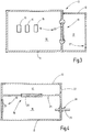
- FIG. 3 Another modification of the housing assembly 10 is from Figure 3 refer to.
- the example illustrated there is based on the housing arrangement 10 according to FIG Figure 1 the partial housing 12 having at least one opening 27 which connects the interior 17 with the free environment.
- This opening 27 is not designed to be flame-proof. For this reason, there are no ignition sources in the interior 17 either. Any components arranged there are designed in such a way that they cannot cause an explosion. This can be, for example, dormant contacts or other means. Components 13 to 15 forming ignition sources are arranged exclusively in the interior 16.
- a pressure relief device 19 is provided in this example, in which the porous body 20 at the edge of the opening 18 is connected to the material of the housing 11 by primary molding, for example by inserting the porous body 20 into the casting mold when casting the housing 11 and was partially enclosed by the housing wall material.
- This type of arrangement of the porous body 20 in or on the wall 25 of the housing 11 can be used in any of the examples described above or below. This both when the body 20 connects the interior spaces 16, 17 to one another and when the porous body 20 connects the interior space 16 with the environment.
- FIG 4 An example with double depressurization is Figure 4 refer to.
- the porous body 20 can be fastened in or on the intermediate wall 25 in any of the ways described above.
- the subspace 17 can be connected to the environment via the opening 27.
- FIG Figure 4 To illustrate the optional possibility of the presence of passages or gaps between the interior 16 and the environment is shown in FIG Figure 4 a bushing 28 for a mechanical element, for example a shaft 29, is illustrated.
- the gap formed between the shaft 29 and the corresponding housing bushing 28 is narrow and long and therefore flame-proof.
- Such or similar arrangements can be provided in all of the examples described above or below.
- the housing 11 can be provided with a further pressure relief arrangement 30 which is formed by a porous body 31.
- a porous body 31 This is gas-permeable and flame-retardant. Its construction and structure can correspond to the porous body 20, so that reference is made accordingly to its description. In addition, it can be connected to the housing wall in any of the aforementioned ways.
- the additional pressure relief body 30 can be made significantly smaller and attached to a suitable location on the housing, for example on the underside of the housing. It can be protected against environmental influences by this or by other measures, e.g. a tearable protective membrane. Such membranes can tear when a gas flow emerges and open the way for it. But then they have to be replaced. Due to the pressure relief volume, however, minor deflagrations do not lead to the destruction of such a protective membrane, so that frequent membrane replacement is not necessary.
- FIG Figure 5 Another possibility of forming a pressure relief volume 22 in the housing 11 is shown in FIG Figure 5 , one embodiment of the present invention.
- the partial housing 12 is arranged in the interior 16 and thus completely surrounded by the housing 11.
- the wall arrangement of the partial housing 12 can be formed entirely or partially by the porous body 20, which accordingly delimits the interior space 17, optionally together with the remaining housing wall of the housing 11.
- the interior 17, which is delimited by the interior 16 and which forms the pressure relief volume 22, is in turn delimited by the pressure relief body 20 in a flame-proof manner. If, for example, an explosion is ignited in the interior space 16 on one of the components 13 to 15, a surge of hot, compressed gases builds up, which cool down as they penetrate the porous body 20 and thus decrease in volume.
- the pressure relief volume 22 thus acts as an absorption volume for the effective reduction of pressure peaks in the housing 11.
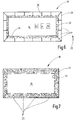
- the housing arrangement 10 as a double-walled housing, wherein the interior 16 enclosed by the inner housing wall 32 can accommodate components 13, 14, 15 forming ignition sources.
- One or more chambers are formed between the inner housing wall 32 and the outer housing wall 33, the inner spaces 17 of which together form the pressure relief volume 22.
- the inner wall 32 may be provided with a number of openings so that all of them are between the housing 32, 33 existing chambers are in open connection with the interior 16.
- Pressure relief bodies can in turn be arranged in the openings or, as shown in FIG Figure 6 As shown, a flameproof liner 34 can prevent flames from penetrating into the chambers 17.
- the flame-retardant lining is preferably formed by one or more flame-retardant porous bodies, for example metal foams, metal felts, metal mesh, metal sintered bodies, ceramic sintered bodies, ceramic fiber bodies and the like. Due to the cooling effect and expansion cooling of the gas penetrating the lining 34, the pressure relief volume 22 acts as an absorption volume to avoid pressure peaks.
- a particularly light and stable housing structure can be achieved with the double-walled housing.
- Further openings for the passage of cables or mechanical movable elements can be arranged on the housing arrangement 10 to break through the housing walls 32, 33.
- these openings are also designed to be flame-proof, as is customary with Ex-d enclosures.
- FIG. 7 A modified example of the housing assembly 10 is illustrated Figure 7 .
- This is again a two-shell housing structure with an inner wall 32 and an outer wall 33, between which individual chambers are arranged, which together form the interior 17 and thus the pressure relief volume 22.
- the inner housing wall 32 is provided with openings, so that each of the chambers preferably communicates with the interior space 16.
- One or more of the chambers are at least partially or completely filled with a porous material in order to bring about a cooling and thus a reduction in volume of the explosion wave running into the interior space 17.
- the housing arrangement 10 has an interior 16 for receiving components 13, 14, 15 which can form ignition sources.
- the housing arrangement 10 also has a partial housing 12 which is arranged in the housing 11 and whose interior 17 serves as a pressure relief volume 22.
- the two interior spaces 16, 17 are connected to one another via a through opening 18 in which a gas-permeable and flame-arresting arrangement 19 is provided.
- This can be formed, for example, by a porous body 20, which is designed to be gas-permeable and has a throttling and cooling effect on a gas flow passing through it.
Landscapes
- Engineering & Computer Science (AREA)
- Power Engineering (AREA)
- Microelectronics & Electronic Packaging (AREA)
- Casings For Electric Apparatus (AREA)
- Air Bags (AREA)
- Gas Exhaust Devices For Batteries (AREA)
Description
- Gegenstand der Erfindung ist ein explosionsgeschütztes Gehäuse, insbesondere ein Gehäuse der Schutzart Ex-d, nach Anspruch 1.
- Gehäuse der Schutzart Ex-d werden häufig in explosionsgefährdeten Bereichen eingesetzt. Solche Gehäuse sind so robust ausgebildet, dass sie einer im Gehäuseinneren stattfindenden Zündung eines explosiven Gasgemisches und der darauf folgenden Druckerhöhung standhalten. Außerdem sind die Gehäuse so gestaltet, dass keine Flammen oder glühende, als Zündquellen wirkende Partikel nach außen gelangen können. Sollten Spalte vorhanden sein, müssen diese eine Mindestlänge aufweisen und dürfen eine Höchstweite nicht überschreiten. Außerdem sind Gehäuseöffnungen mit Druckentlastungskörpern versehen, die auch als Flammenschutzfilter bezeichnet werden und verhindern, dass eine im Gehäuse gezündete Explosion nach außen dringt und in der Umgebung vorhandenes explosionsfähiges Gemisch zündet.
- Ein Beispiel für ein explosionsgeschütztes Gehäuse ist der DD
261 063 A3 zu entnehmen. Das dort veranschaulichte Gehäuse weist in seinem Innenraum einen porösen Körper beispielsweise aus Schlackenwolle, Glaswolle oder Metall oder Keramik mit offenen durchgehenden Poren oder Spalten auf. Dieser Körper soll zu einer Senkung des Explosionsdrucks um ca. 90% führen. - Ebenso offenbart die
DE 198 60 386 B4 ein für einen Bildschirm vorgesehenes Gehäuse, dessen Innenraum teilweise mit einem porösen Explosionsdruck-Dämpfungsmaterial gefüllt ist. Dieses weist eine Vielzahl im Querschnitt kleiner, nicht geschlossener, sondern durchgehender Kanäle in Form von Poren und/oder Spalten auf. Der Explosionsdruck soll auf lediglich etwa 10% des Explosionsdrucks gedämpft werden, der sonst in dem leeren Gehäuse auftreten würde. - Ähnlich sieht die
DE 10 2014 206 433 B3 die Anordnung eines Tablets-Computers in einem mit einer Glasscheibe versehenen explosionssicheren Gehäuse auf, wobei in dem Tablet-Computer ein Dämpfungselement aus offenporiger Stein-, Quarz- oder Glaswolle, Metallschaum oder dergleichen, angeordnet ist. - Die insoweit vorgestellten Gehäuselösungen erfordern zur Senkung des Explosionsdrucks Dämpfungskörper mit erheblichem Volumen, womit der Gehäuseinnenraum nur unzulänglich ausgenutzt wird.
- Aus der
DE 10 2013 109 259 A1 ist dagegen ein explosionsgeschütztes Gehäuse der Schutzart "druckfeste Kapselung" (Ex-d) bekannt, in dessen Gehäusewand ein poröser Druckentlastungskörper vorgesehen ist, durch den ein im Gehäuse aufgebauter Explosionsdruck nach außen dringen kann. - Das Dokument
DE 10 2013 109 260 A1 offenbart ferner die Präambel des unabhängigen Anspruchs 1. - Ein ähnliches Prinzip nutzen die Gehäuse nach der
US 4,180,177 sowie nach derDE 10 2010 016 782 B4 . - Außerdem ist aus der
DE 10 2014 116 149 A1 ein vorteilhafter Aufbau eines Druckentlastungskörpers bekannt. Dieser besteht aus mehreren Drahtgewebelagen unterschiedlicher Ausrichtung und Maschenweite, wobei diese Lagen durch einen Sinterprozess miteinander verbunden worden sind. Bei Anordnung solcher Gehäuse in widriger Umgebung, beispielsweise mit Staub beladener Atmosphäre oder mit direkter Wetterbeaufschlagung, bedürfen die Druckentlastungskörper in den Gehäuseöffnungen besonderen Schutzes, beispielsweise gegen Verschmutzung, Verkeimung, Korrosion und/oder Vereisung. - Es ist Aufgabe der Erfindung, ein Konzept für ein explosionsgeschütztes Gehäuse anzugeben, mit dem sich ein oder mehreren der oben genannten Nachteile vermeiden lassen.
- Diese Aufgabe wird mit der explosionsgeschützten Gehäuseanordnung nach Anspruch 1 gelöst.
- Die erfindungsgemäße Gehäuseanordnung weist ein Gehäuse auf, das einen Innenraum umschließt, der zur Aufnahme von Komponenten geeignet ist, die Zündquellen bilden können. In dem Gehäuse ist ein Entlastungsvolumen vorgesehen. Dieses ist in dem Innenraum angeordnet. Es ist dabei wenigstens eine Durchgangsöffnung vorgesehen, die den Innenraum mit dem Druckentlastungsvolumen verbindet, wobei in dieser Durchgangsöffnung eine gasdurchlässige und flammendurchschlagsichere Anordnung angeordnet ist. Bei dieser handelt es sich typischerweise um einen porösen, mechanisch stabilen Körper mit einer Vielzahl von vorzugsweise ein- oder mehrfach verzweigten Porenkanälen, die zwei voneinander weg weisende Seiten des Körpers miteinander verbinden. Der Druckentlastungskörper kann beispielsweise ein poröser Metallkörper, poröser Keramickörper, poröser Glaskörper, ein aus Metallpartikeln oder Keramikpartikeln gesinterter Körper oder ein aus mehreren miteinander verbundenen Drahtnetzlagen bestehender Körper sein.
- Der Druckentlastungskörper kann mit der Wandanordnung verklebt, verschweißt oder auch mechanisch zum Beispiel durch einen Klemmrahmen, durch Klemmschrauben oder dergleichen verbunden sein. Der Druckentlastungskörper kann an der Gehäusewand angebracht oder beim Urformen der Gehäusewand in diese eingebracht sein.
- Erfindungsgemäß befindet sich auf einer Seite der flammendurchschlagsicheren Anordnung derjenige Teil des Innenraums, in dem Zündquellen bildende Komponenten angeordnet sind während auf der anderen Seite der flammendurchschlagsicheren, gasdurchlässigen Anordnung ein Volumen abgegrenzt ist, das frei von Zündquellen bildenden Komponenten ist. Beispielsweise kann der die Komponenten enthaltende Teil des Innenraums zu einem explosionsgeschützten Gehäuse Ex-d gehören, während das Druckentlastungsvolumen nach einer anderen Schutzart, zum Beispiel Ex-e, ausgebildet ist. Es kann somit zur Umgebung hin offene Öffnungen aufweisen. Jedenfalls aber ist die gasdurchlässige flammendurchschlagsichere Anordnung direkten Umgebungseinflüssen und somit Staubablagerung, Vereisung usw. entzogen.
- Die Kombination der gasdurchlässigen und flammendurchschlagsicheren Anordnung, zum Beispiel in Gestalt eines steifen, porösen Körpers (beispielsweise eines Metallnetzlagen-Sinterkörpers), mit einem Druckentlastungsvolumen, vermindert im Vergleich zu Dämpfungskörpern, wie sie aus dem Stand der Technik bekannt sind, den Volumenbedarf der Druckreduzierungsanordnung. Diese besteht bei der Erfindung aus der gasdurchlässigen flammendurchschlagsicheren Anordnung und dem das Druckentlastungsvolumen enthaltenden Teilgehäuse. Letzteres hat im Vergleich zu einem gleich großen porösen Körper ein höheres Schluckvermögen. Durch die expansionsbedingte Abkühlung der den porösen Körper durchdringenden Gasmenge wirkt das Druckentlastungsvolumen besonders stark druckreduzierend. Auch ist der Strömungswiderstad des freien Druckentlastungsvolumens deutlich geringer als der Strömungswiderstand innerhalb eines porösen Dämpfungskörpers, was insbesondere dem Abbau der Druckspitze nach Auslösung einer Explosion dient.
- Weitere Einzelheiten vorteilhafter Ausführungsformen der Erfindung sind Gegenstand der beigefügten Ansprüche. Es zeigen:
-
Figur 1 ein explosionsgeschütztes Gehäuse, nicht Teil der Erfindung, mit Druckentlastungsvolumen und dazwischen angeordnetem Druckentlastungskörper, in schematisierter Schnittdarstellung, -
Figur 2 bis 4 weitere Beispiele, nicht Teil der Erfindung, undFigur 5 , eine Ausführungsform der vorliegenden Erfindung explosionsgeschützter Gehäuse mit Druckentlastungsvolumen jeweils, in schematisierter Schnittdarstellung, -
Figur 6 ein nicht Teil der Erfindung doppelwandiges explosionsgeschütztes Gehäuses mit als Druckentlastungsvolumen dienenden Wandinnenräumen, in schematisierter Schnittdarstellung, und -
Figur 7 ein nicht Teil der Erfindung explosionsgeschütztes doppelwandiges Gehäuse mit Wandvolumina, die mit porösem Material wenigstens teilweise gefüllt sind. - Das Gehäuse 11 besteht typischerweise aus Metall, beispielsweise Stahl oder Aluminium, es kann jedoch auch aus einem geeigneten Kunststoff oder Kunststoffverbundmaterial ausgebildet sein. Es schließt unmittelbar an das Teilgehäuse 12 an, das aus gleichem oder anderem Material bestehen kann. Das Teilgehäuse 12 umschließt ebenfalls einen Innenraum 17, in dem keine weiteren Bauteile oder Komponenten oder wenigstens keine Bauteile oder Komponenten angeordnet sind, die Zündquellen bilden können. Solche Komponenten können beispielsweise ruhende Kontakte z.B. in Form von elektrischen Anschlusskontakten sein. In diesem Fall ist das Gehäuse 11 zum Beispiel nach der Schutzart Ex-d (druckfeste Kapselung) ausgebildet, was bedeutet, dass jede Verbindung zwischen dem Innenraum 16 und der Umgebung flammendurchschlagssicher ausgebildet ist, wobei die Gehäusewand des Gehäuses 11 der Druckbelastung einer im Innenraum 16 stattfindenden Explosion standhält. Das Teilgehäuse 12 kann hingegen nach einer anderen Schutzart, zum Beispiel Ex-e ausgebildet sein, was bedeutet, dass in dem Innenraum 17 keine Zündquellen bildenden Elemente vorgesehen sind.
- Es ist auch möglich, sowohl das Gehäuse 11 als auch das Teilgehäuse 12 nach gleichem Standard, z.B. als druckfeste Kapselung nach (Ex-d) auszubilden. In diesem Falle können sowohl in dem Gehäuse 11 als auch in dem Teilgehäuse 12 Zündquellen bildende Komponenten vorhanden sein. Dies insbesondere, wenn die in den beiden Innenräumen 16, 17 vorhandenen potentiellen Zündquellen nicht gleichzeitig aktiv sind.
- Das Gehäuse 11 weist an einer Wand 25 eine Durchgangsöffnung 18 auf, die den Innenraum 16 mit dem Innenraum 17 verbindet. Die Wand 25 ist integraler Bestandteil des Gehäuses 11 oder des Teilgehäuses 12. In oder an der Durchgangsöffnung 18 ist eine flammendurchschlagsichere Anordnung 19 vorgesehen, die gasdurchlässig ausgebildet und beispielsweise durch einen porösen Körper 20 gebildet ist. Dieser kann beispielsweise ein Metallschaumkörper, Keramikschaumkörper oder ein aus Drahtgewebe, Drahtgestrick, Drahtfilz oder dergleichen gebildeter Körper sein. Insbesondere ist der poröse Körper 20 biegesteif ausgebildet und an seinem Rand 21 mit der Gehäusewand verbunden. Die Verbindung ist vorzugsweise spaltfrei, so dass durch die Durchgangsöffnung 18 strömendes Gas den porösen Körper 20 nicht umgehen kann.
- Die insoweit beschriebene Gehäuseanordnung 10 kann in explosionsgefährdeter Umgebung eingesetzt werden. Sollten durch nicht weiter veranschaulichte Spalte oder auf sonstigem Wege explosionsfähige Gase in den Innenraum 16 und gegebenenfalls auch 17 eingedrungen sein, können diese an einer der Komponenten 13 bis 15 das Gas zu einem zufälligen Zeitpunkt zünden und zu einer Explosion in dem Innenraum 16 führen. Das Gehäuse 11 weist keine Öffnungen oder Spalten auf, durch die Flammen oder heiße Partikel nach außen dringen könnten. Alle Fugen, Spalten und sonstigen nicht gasdichten Strukturen sind flammendurchschlagsicher.
- Die in dem Innenraum 16 initiierte Explosion führt zunächst zu einer Erwärmung und Ausdehnung des vorhandenen Gasvolumens, was mit einer Druckerhöhung einhergeht. Die flammendurchschlagsichere Anordnung 19 bewirkt jedoch eine Druckentlastung, indem sie einen Gasstrom aus dem Innenraum 16 in den Innenraum 17 übertreten lässt. Die durch den porösen Körper 20 in den Innenraum 17 dringenden Gase kühlen sich durch Wärmeabgabe an dem porösen Körper 20 sowie durch Expansion zum Beispiel adiabatisch und/oder durch den Jules Thompson Effekt ab. Dadurch kann der Innenraum 17 ein Gasvolumen aufnehmen, das größer ist als das Gasvolumen, das den Innenraum 16 durch die Durchgangsöffnung 18 verlassen hat. Der Innenraum 17 bildet somit ein sehr wirksames Druckentlastungsvolumen 22 für den Innenraum 16.
- Zusätzlich hält das Teilgehäuse 12 Umwelteinflüsse von der flammendurchschlagsicheren Anordnung 19 fern, so dass diese insbesondere vor Verstaubung, Verschmutzung, Verkeimung, Vereisung und dergleichen Einflüssen geschützt ist. Insbesondere werden Umwelteinflüssen ferngehalten, die zu einer Verringerung der Gasdurchlässigkeit der flammendurchschlagsicheren Anordnung 19 führen können.
- Sowohl die im Innenraum 16 zugewandte Fläche 23 als auch die im Druckentlastungsvolumen 22 zugewandte Fläche 24 sind dauerhaft geschützt.
-
Figur 2 veranschaulicht ein abgewandeltes Beispiel der Gehäuseanordnung 10, bei der das Gehäuse 11 und das Teilgehäuse 12 durch einen gemeinsamen Gehäusekörper gebildet sind. Das Druckentlastungsvolumen 22 ist von dem Innenraum 16 durch eine Zwischenwand 25 abgetrennt, die integraler Bestandteil des Gehäusekörpers ist und in der die Durchgangsöffnung 18 mit der darin angeordneten Druckentlastungsanordnung 19 angeordnet ist. Der zu dieser gehörige poröse Körper 20 kann wiederum auf jede geeignete Art mit dem Rand der Druckentlastungsöffnung 18 verbunden sein, beispielsweise über eine mit der Zwischenwand 25 verklebte, verschraubte, verschweißte, verlötete oder sonst wie verbundene Fassung 26, in der der poröse Körper 20 gehalten ist. - Für alle Beispiele und die Ausführungsform gilt, dass der Innenraum 16 des Gehäuses 11 vorzugsweise größer als der Innenraum 17 des Teilgehäuses 12 ist. Nicht dargestellte Komponenten, die potentiell Zündquellen darstellen, können in dem Innenraum 16 angeordnet sein. Der Innenraum 17 ist vorzugsweise frei von Zündquellen.
- Eine weitere Abwandlung der Gehäuseanordnung 10 ist aus
Figur 3 zu entnehmen. Das dort veranschaulichte Beispiel beruht auf der Gehäuseanordnung 10 nachFigur 1 wobei das Teilgehäuse 12 mindestens eine Öffnung 27 aufweist, die den Innenraum 17 mit der freien Umgebung verbindet. Diese Öffnung 27 ist nicht flammendurchschlagsicher ausgebildet. Deswegen sind in dem Innenraum 17 auch keine Zündquellen vorhanden. Jegliche dort angeordneten Komponenten sind so ausgebildet, dass von ihnen keine Explosion ausgehen kann. Es kann sich dabei zum Beispiel um ruhende Kontakte oder andere Mittel handeln. Zündquellen bildende Komponenten 13 bis 15 sind ausschließlich in dem Innenraum 16 angeordnet. - Lediglich beispielhaft ist in diesem Beispiel eine Druckentlastungsvorrichtung 19 vorgesehen, bei der der poröse Körper 20 am Rand der Öffnung 18 mit dem Material des Gehäuses 11 durch Urformen verbunden ist, beispielsweise, indem der poröse Körper 20 beim Gießen des Gehäuses 11 in dessen Gussform eingelegt worden ist und teilweise von dem Gehäusewandmaterial umschlossen wurde. Diese Art der Anordnung des porösen Körpers 20 in oder an der Wand 25 des Gehäuses 11 kann bei jeder der vor- oder nachstehend beschriebenen Beispiele zur Anwendung kommen. Dies sowohl, wenn der Körper 20 die Innenräume 16, 17 miteinander verbindet als auch wenn der poröse Körper 20 den Innenraum 16 mit der Umgebung verbindet.
- Ein Beispiel mit doppelter Druckentlastung ist
Figur 4 zu entnehmen. Es ist dort eine Gehäusestruktur nach dem Vorbild der Gehäuseanordnung 10 nachFigur 2 dargestellt, wobei der poröse Körper 20 nach jeder der vorbeschriebenen Arten in oder an der Zwischenwand 25 befestigt sein kann. Optional kann der Teilraum 17 über die Öffnung 27 mit der Umgebung verbunden sein. - Zur Veranschaulichung der optionalen Möglichkeit des Vorhandenseins von Durchgängen oder Spalten zwischen dem Innenraum 16 und der Umgebung ist in
Figur 4 eine Durchführung 28 für ein mechanisches Element, beispielsweise eine Welle 29 veranschaulicht. Der zwischen der Welle 29 und der entsprechenden Gehäusedurchführung 28 gebildete Spalt ist eng und lang und deswegen flammendurchschlagsicher. Solche oder ähnliche Anordnungen können bei allen vor- oder nachstehend beschriebenen Beispiele vorgesehen sein. - Das Gehäuse 11 kann mit einer weiteren Druckentlastungsanordnung 30 versehen sein, die durch einen porösen Körper 31 gebildet ist. Dieser ist gasdurchlässig und flammendurchschlagsicher. Er kann in Aufbau und Struktur mit dem porösen Körper 20 übereinstimmen, so dass auf dessen Beschreibung entsprechend verweisen wird. Außerdem kann er auf jede der vorgenannten Arten mit der Gehäusewand verbunden sein.
- Im Beispiel nach
Figur 4 ist der poröse Körper 20 vor Verschmutzung und Witterungseinflüssen geschützt. Der zusätzliche Druckentlastungskörper 30 kann deutlich kleiner ausgebildet sein und an einer geeigneten Gehäusestelle zum Beispiel an der Gehäuseunterseite angebracht sein. Er kann dadurch oder durch weitere Maßnahmen, z.B. eine reißfähige Schutzmembrane gegen Umwelteinflüsse geschützt werden. Solche Membranen können bei Austritt eines Gasstroms zerreißen und den Weg für diesen frei geben. Sie müssen dann aber ersetzt werden. Durch das Druckentlastungsvolumen führen jedoch kleinere Verpuffungen nicht zur Zerstörung einer solchen Schutzmembrane, so dass kein häufiger Membrane-Austausch erforderlich wird. - Eine weitere Möglichkeit der Ausbildung eines Druckentlastungsvolumens 22 in dem Gehäuse 11 ist in
Figur 5 , einer Ausführungsform der vorliegenden Erfindung, veranschaulicht. Bei der dort dargestellten Gehäuseanordnung 10 ist das Teilgehäuse 12 in dem Innenraum 16 angeordnet und somit vollständig von dem Gehäuse 11 umgeben. Die Wandanordnung des Teilgehäuses 12 kann ganz oder teilweise durch den porösen Körper 20 gebildet sein, der entsprechend den Innenraum 17 gegebenenfalls zusammen mit der verbleibenden Gehäusewand des Gehäuses 11 abgrenzt. Der von dem Innenraum 16 abgegrenzte Innenraum 17, der das Druckentlastungsvolumen 22 bildet, ist durch den Druckentlastungskörper 20 wiederum flammendurchschlagsicher abgegrenzt. Wird in dem Innenraum 16 zum Beispiel an einer der Komponenten 13 bis 15 eine Explosion gezündet, baut sich ein Schwall heißer verdichteter Gase auf, die beim Durchdringen des porösen Körpers 20 abkühlen und dadurch an Volumen abnehmen. Das Druckentlastungsvolumen 22 wirkt somit als Schluckvolumen zur wirksamen Herabsetzung von Druckspitzen in den Gehäuse 11. - Wie
Figur 6 veranschaulicht, als ein nicht zur Erfindung gehörendes Beispiel, ist es auch möglich, die Gehäuseanordnung 10 als doppelwandiges Gehäuse aufzubauen, wobei der von der inneren Gehäusewand 32 umschlossen Innenraum 16 Zündquellen bildende Komponenten 13, 14, 15 aufnehmen kann. Zwischen der inneren Gehäusewand 32 und der äußeren Gehäusewand 33 sind ein oder mehrere Kammern ausgebildet, deren Innenräume 17 gemeinsam das Druckentlastungsvolumen 22 bilden. - Die Innenwand 32 kann mit einer Anzahl von Öffnungen versehen sein, so dass alle zwischen dem Gehäuse 32, 33 vorhandenen Kammern in offener Verbindung zu dem Innenraum 16 stehen. In den Öffnungen können wiederum Druckentlastungskörper angeordnet sein oder, wie es in
Figur 6 dargestellt ist, kann eine flammendurchschlagsichere Auskleidung 34 dem Flammendurchschlag in die Kammern 17 verhindern. Dabei ist die flammendurchschlagsichere Auskleidung vorzugsweise durch einen oder mehrere flammendurchschlagsichere poröse Körper, beispielsweise Metallschäume, Metallfilze, Metallgewebe, Metallsinterkörper, Keramiksinterkörper, Keramikfaserkörper und dergleichen gebildet. Durch die Kühlwirkung und Expansionskühlung des die Auskleidung 34 durchdringenden Gases wirkt das Druckentlastungsvolumen 22 als Schluckvolumen zur Vermeidung von Druckspitzen. - Zugleich kann mit dem doppelwandigen Gehäuse ein besonders leichter und stabiler Gehäuseaufbau erreicht werden. Weitere Öffnungen zur Durchleitung von Kabeln oder mechanischen beweglichen Elementen können an der Gehäuseanordnung 10 die Gehäusewände 32, 33 durchbrechend angeordnet sein. Diese Öffnungen sind jedoch ebenfalls flammendurchschlagsicher ausgebildet, wie es bei Ex-d Gehäusen üblich ist.
- Ein abgewandeltes Beispiel der Gehäuseanordnung 10 veranschaulicht
Figur 7 . Es handelt sich dort wiederum um eine zweischaligen Gehäuseaufbau mit einer Innenwand 32 und einer Außenwand 33, zwischen denen einzelne Kammern angeordnet sind, die zusammen den Innenraum 17 und somit das Druckentlastungsvolumen 22 bilden. Die innere Gehäusewand 32 ist mit Öffnungen versehen, so dass vorzugsweise jede der Kammern mit dem Innenraum 16 kommuniziert. Eine oder mehrere der Kammern sind mit einem porösen Material wenigstens teilweise oder auch ganz gefüllt, um eine Abkühlung und somit Volumenverringerung der in den Innenraum 17 laufenden Explosionswelle zu bewirken. - Die erfindungsgemäße Gehäuseanordnung 10 weist einen Innenraum 16 zur Aufnahme von Komponenten 13, 14, 15 auf, die Zündquellen bilden können. Weiter weist die Gehäuseanordnung 10 ein Teilgehäuse 12 auf, das in dem Gehäuse 11 angeordnet ist und dessen Innenraum 17 als Druckentlastungsvolumen 22 dient. Die beiden Innenräume 16, 17 sind über eine Durchgangsöffnung 18 miteinander verbunden, in der eine gasdurchlässige und flammendurchschlagsichere Anordnung 19 vorgesehen ist. Diese kann zum Beispiel durch einen porösen Körper 20 gebildet sein, der gasdurchlässig ausgebildet ist und auf einen durch ihn hindurchtretenden Gasstrom drosselnd und kühlend wirkt.
Bezugszeichen: 10 Gehäuseanordnung 11 Gehäuse 12 Teilgehäuse 13 - 15 Komponenten 16 Innenraum des Gehäuses 11 17 Innenraum des Teilgehäuses 12 18 Durchgangsöffnung in der Wand des Gehäuses 11 19 flammendurchschlagsichere Anordnung 20 poröser Körper 21 Rand des Körpers 20 22 Druckentlastungsvolumen 23 dem Innenraum 16 zugewandte Fläche des Körpers 20 24 dem Innenraum 17 zugewandte Fläche des Körpers 20 25 Zwischenwand 26 Fassung 27 Öffnung 28 Durchführung 29 Welle 30 Druckentlastungsanordnung 31 poröser Körper 32 innere Gehäusewand 33 äußere Gehäusewand 34 flammendurchschlagsichere Auskleidung
Claims (4)
- Gehäuseanordnung (10), insbesondere Gehäuse der Schutzart ex-d,mit einem Gehäuse (11), das einen Innenraum (16) umschließt, der zur Aufnahme von Komponenten geeignet ist, die Zündquellen bilden können,mit einem in dem Gehäuse (11) angeordneten Entlastungsvolumen (22),mit einer Durchgangsöffnung (18), die den Innenraum (16) mit dem Druckentlastungsvolumen (22) verbindend angeordnet ist,mit einer in oder an der Durchgangsöffnung (18) angeordneten, gasdurchlässigen und flammendurchschlagsicheren Anordnung (19),dadurch gekennzeichnet, dass das Druckentlastungsvolumen (22) innerhalb des von dem Gehäuse (11) umschlossenen Innenraums (16) abgegrenzt ist, wobeidas Druckentlastungsvolumen (22) in einem in dem Innenraum (16) angeordneten Teilgehäuse (12) gebildet ist.
- Gehäuseanordnung nach Anspruch 1, wobei das Teilgehäuse (12) mit dem Gehäuse (11) wenigstens eine Wand gemeinsam hat.
- Gehäuseanordnung nach einem der vorstehenden Ansprüche, wobei die Durchgangsöffnung (18) wenigstens eine Wandfläche des Teilgehäuses (12) bildet.
- Gehäuseanordnung nach Anspruch 1, wobei das Teilgehäuse (12) eine Schutzart aufweist, die sich von der Schutzart des Gehäuses (11) unterscheidet.
Applications Claiming Priority (2)
| Application Number | Priority Date | Filing Date | Title |
|---|---|---|---|
| DE102017112153.6A DE102017112153A1 (de) | 2017-06-01 | 2017-06-01 | Explosionssicheres Gehäuse mit innerer Druckentlastung |
| PCT/EP2018/063338 WO2018219712A1 (de) | 2017-06-01 | 2018-05-22 | Explosionssicheres gehäuse mit innerer druckentlastung |
Publications (2)
| Publication Number | Publication Date |
|---|---|
| EP3631924A1 EP3631924A1 (de) | 2020-04-08 |
| EP3631924B1 true EP3631924B1 (de) | 2021-09-15 |
Family
ID=62244478
Family Applications (1)
| Application Number | Title | Priority Date | Filing Date |
|---|---|---|---|
| EP18726966.7A Not-in-force EP3631924B1 (de) | 2017-06-01 | 2018-05-22 | Explosionssicheres gehäuse mit druckentlastung |
Country Status (6)
| Country | Link |
|---|---|
| US (1) | US11252830B2 (de) |
| EP (1) | EP3631924B1 (de) |
| CN (1) | CN110832717A (de) |
| DE (1) | DE102017112153A1 (de) |
| RU (1) | RU2747415C1 (de) |
| WO (1) | WO2018219712A1 (de) |
Families Citing this family (8)
| Publication number | Priority date | Publication date | Assignee | Title |
|---|---|---|---|---|
| DE102017112150B4 (de) * | 2017-06-01 | 2019-02-07 | R.Stahl Schaltgeräte GmbH | Explosionssicheres Gehäuse mit innerer Druckreduzierung |
| DE102018120877B4 (de) * | 2018-08-27 | 2021-09-30 | R.Stahl Schaltgeräte GmbH | Explosionsgeschütztes Gehäuse |
| DE102019113193A1 (de) | 2019-05-17 | 2020-11-19 | R. Stahl Schaltgeräte GmbH | Baukastensystem zum Herstellen eines Gehäuses |
| DE102019113194B4 (de) | 2019-05-17 | 2021-02-11 | R.Stahl Schaltgeräte GmbH | Baukastensystem |
| CN111525419B (zh) * | 2020-05-09 | 2021-09-17 | 裕成电器有限公司 | 一种带有燃弧阻断装置的金属封闭式开关柜 |
| RU200585U1 (ru) * | 2020-06-11 | 2020-10-30 | Федеральное государственное унитарное предприятие "Центральный ордена Трудового Красного Знамени научно-исследовательский автомобильный и автомоторный институт "НАМИ" (ФГУП "НАМИ") | Корпус электронного блока управления |
| DE202022104795U1 (de) | 2022-08-25 | 2022-09-23 | Condensator Dominit Gmbh | Schaltschrank und Elemente für einen Schaltschrank |
| WO2026053010A1 (en) * | 2024-09-06 | 2026-03-12 | Abb Schweiz Ag | Porous, flame-quenching linings in flame paths of motor enclosures to reduce peak explosion pressure and prevent flame transmission |
Family Cites Families (19)
| Publication number | Priority date | Publication date | Assignee | Title |
|---|---|---|---|---|
| US2789238A (en) * | 1954-08-02 | 1957-04-16 | Gen Electric | Flame arrestor for dynamoelectric machines |
| US4180177A (en) | 1979-04-04 | 1979-12-25 | The United States Of America As Represented By The Secretary Of The Interior | Pressure vent for explosion-proof electrical enclosures |
| US4484690A (en) * | 1982-03-08 | 1984-11-27 | Service Machine Co. | Flame arresting ventilated wall for an explosion-proof enclosure |
| DD261063A3 (de) | 1984-11-19 | 1988-10-19 | Bergbausicherheit Inst | Anordnung zum reduzieren von explosionsdruecken in geschlossenen raeumen |
| DE9213806U1 (de) * | 1992-10-14 | 1993-05-06 | Beton- Elemente- und Baustoffwerk Heinrich Gräper GmbH & Co KG, 2907 Großenkneten | (Kompakt-)Schaltstation für eine elektrische Schalteinrichtung |
| DE4442363A1 (de) * | 1994-11-18 | 1996-05-23 | Siemens Ag | Sicherungskammerverschluß im Sicherungsanbau |
| DE19860383B4 (de) | 1998-12-28 | 2005-06-09 | Bartec Gmbh | Bildschirm |
| DE102010016782B4 (de) | 2010-05-04 | 2016-12-08 | R.Stahl Schaltgeräte GmbH | Druckentlastungsvorrichtung für druckfest gekapselte Gehäuse |
| WO2012067861A2 (en) * | 2010-11-19 | 2012-05-24 | Abb Technology Ag | Pressure relief system for switchgear |
| DE102012207013A1 (de) * | 2012-04-27 | 2013-10-31 | Siemens Aktiengesellschaft | Belüftung eines elektrischen Gerätes |
| DE102013109260A1 (de) * | 2013-08-27 | 2015-03-05 | R.Stahl Schaltgeräte GmbH | Gehäuseteil für ein explosionsgeschütztes Gehäuse mit einem porösen Körper |
| DE102013109259A1 (de) | 2013-08-27 | 2015-03-05 | R.Stahl Schaltgeräte GmbH | Druckentlastungsvorrichtung für ein explosionsgeschütztes Gehäuse und Verfahren zu deren Herstellung |
| DE102013109261A1 (de) * | 2013-08-27 | 2015-03-05 | R.Stahl Schaltgeräte GmbH | Druckentlastungsvorrichtung für druckfest gekapselte Gehäuse mit einem porösen Körper mit Übermaßpassung |
| US10745144B2 (en) * | 2014-02-28 | 2020-08-18 | The Boeing Company | Systems and methods for containing ignition within a battery housing |
| DE102014206433B3 (de) | 2014-04-03 | 2015-08-20 | Ecom Instruments Gmbh | Geräte-Anordnung, insbesondere zur Verwendung in einem explosionsgefährdeten Bereich |
| DE102014116149A1 (de) | 2014-11-06 | 2016-05-12 | R. Stahl Schaltgeräte GmbH | Flammenschutzfilter aus einer Anzahl von Schichtenfolgen sowie Anordnungen von Flammenschutzfiltern und deren Verwendung |
| DE102015206355A1 (de) * | 2015-04-09 | 2016-10-13 | Siemens Aktiengesellschaft | Elektrische Schaltanlage |
| RU162661U1 (ru) * | 2015-09-08 | 2016-06-27 | Закрытое акционерное общество "Группа компаний "Электрощит" - ТМ Самара" | Шкаф комплектного распределительного устройства с приспособлением для осушения высоковольтного отсека |
| EP3859873A1 (de) * | 2016-10-04 | 2021-08-04 | Kabushiki Kaisha Toshiba | Druckausgleichsgehäuse |
-
2017
- 2017-06-01 DE DE102017112153.6A patent/DE102017112153A1/de not_active Withdrawn
-
2018
- 2018-05-22 CN CN201880036166.5A patent/CN110832717A/zh active Pending
- 2018-05-22 WO PCT/EP2018/063338 patent/WO2018219712A1/de not_active Ceased
- 2018-05-22 EP EP18726966.7A patent/EP3631924B1/de not_active Not-in-force
- 2018-05-22 US US16/617,886 patent/US11252830B2/en not_active Expired - Fee Related
- 2018-05-22 RU RU2019143709A patent/RU2747415C1/ru active
Also Published As
| Publication number | Publication date |
|---|---|
| US11252830B2 (en) | 2022-02-15 |
| RU2747415C1 (ru) | 2021-05-04 |
| EP3631924A1 (de) | 2020-04-08 |
| CN110832717A (zh) | 2020-02-21 |
| US20200113075A1 (en) | 2020-04-09 |
| DE102017112153A1 (de) | 2018-12-06 |
| WO2018219712A1 (de) | 2018-12-06 |
Similar Documents
| Publication | Publication Date | Title |
|---|---|---|
| DE102017112153A1 (de) | Explosionssicheres Gehäuse mit innerer Druckentlastung | |
| DE2639691C3 (de) | Schutztür | |
| EP1371121B1 (de) | Elektrische anlage mit druckentlastungskanal | |
| DE102017112150B4 (de) | Explosionssicheres Gehäuse mit innerer Druckreduzierung | |
| EP3631925B1 (de) | Explosionssicheres gehäuse mit innerer druckentlastung | |
| DE102019113195B4 (de) | Explosionsgeschütztes Gehäuse | |
| DE2022978A1 (de) | Anordnung mit einer in einem Gehaeuse untergebrachten Einrichtung | |
| EP3199207B1 (de) | Druckentlastungsvorrichtung, modulare druckentlastungseinheit und brandschutzvorrichtung | |
| DE19860383B4 (de) | Bildschirm | |
| EP3818601B1 (de) | Explosionsgeschütztes gehäuse mit druckentlastung | |
| EP3478371B1 (de) | Druckentlastungsvorrichtung | |
| EP3630303B1 (de) | Gehäuse mit eingegossener druckentlastung | |
| EP1922792A1 (de) | Gehäuse für ein elektrisch betriebenes gerät | |
| DE3311252C2 (de) | ||
| AT500367B1 (de) | Wärmedämmplatte | |
| DE102019113194B4 (de) | Baukastensystem | |
| DE202018106804U1 (de) | Aufbewahrungsbehälter und Absorberelement für einen Aufbewahrungsbehälter | |
| DE10044368C2 (de) | Revisionsabdeckung | |
| WO2019043057A1 (de) | Gehäuse der schutzart druckfeste kapselung und herstellungsverfahren für dieses | |
| DE202022104795U1 (de) | Schaltschrank und Elemente für einen Schaltschrank | |
| EP1585203A1 (de) | Gehäuse aus feuerhemmendem Material | |
| AT18312U1 (de) | Gehäuse zur Aufnahme elektronischer Komponenten sowie Wechselrichter mit einem solchen Gehäuse | |
| DE20220394U1 (de) | Feuergeschütztes Gehäuse | |
| WO2011141065A1 (de) | BAUPLATTE, INSBESONDERE ZUR DECKENMONTAGE, SOWIE VERFAHREN ZUM ÖFFNEN ODER SCHLIEßEN EINER REVISIONSÖFFNUNG IN EINER BAUPLATTE | |
| EP1217703A1 (de) | Steuerkasten für einen Aufzug |
Legal Events
| Date | Code | Title | Description |
|---|---|---|---|
| STAA | Information on the status of an ep patent application or granted ep patent |
Free format text: STATUS: UNKNOWN |
|
| STAA | Information on the status of an ep patent application or granted ep patent |
Free format text: STATUS: THE INTERNATIONAL PUBLICATION HAS BEEN MADE |
|
| PUAI | Public reference made under article 153(3) epc to a published international application that has entered the european phase |
Free format text: ORIGINAL CODE: 0009012 |
|
| STAA | Information on the status of an ep patent application or granted ep patent |
Free format text: STATUS: REQUEST FOR EXAMINATION WAS MADE |
|
| 17P | Request for examination filed |
Effective date: 20191202 |
|
| AK | Designated contracting states |
Kind code of ref document: A1 Designated state(s): AL AT BE BG CH CY CZ DE DK EE ES FI FR GB GR HR HU IE IS IT LI LT LU LV MC MK MT NL NO PL PT RO RS SE SI SK SM TR |
|
| AX | Request for extension of the european patent |
Extension state: BA ME |
|
| DAV | Request for validation of the european patent (deleted) | ||
| DAX | Request for extension of the european patent (deleted) | ||
| GRAP | Despatch of communication of intention to grant a patent |
Free format text: ORIGINAL CODE: EPIDOSNIGR1 |
|
| STAA | Information on the status of an ep patent application or granted ep patent |
Free format text: STATUS: GRANT OF PATENT IS INTENDED |
|
| INTG | Intention to grant announced |
Effective date: 20210531 |
|
| RIN1 | Information on inventor provided before grant (corrected) |
Inventor name: HERMANOWSKI, CLIFE Inventor name: ARNHOLD, THORSTEN |
|
| GRAS | Grant fee paid |
Free format text: ORIGINAL CODE: EPIDOSNIGR3 |
|
| GRAA | (expected) grant |
Free format text: ORIGINAL CODE: 0009210 |
|
| STAA | Information on the status of an ep patent application or granted ep patent |
Free format text: STATUS: THE PATENT HAS BEEN GRANTED |
|
| AK | Designated contracting states |
Kind code of ref document: B1 Designated state(s): AL AT BE BG CH CY CZ DE DK EE ES FI FR GB GR HR HU IE IS IT LI LT LU LV MC MK MT NL NO PL PT RO RS SE SI SK SM TR |
|
| REG | Reference to a national code |
Ref country code: CH Ref legal event code: EP |
|
| REG | Reference to a national code |
Ref country code: DE Ref legal event code: R096 Ref document number: 502018007088 Country of ref document: DE |
|
| REG | Reference to a national code |
Ref country code: IE Ref legal event code: FG4D Free format text: LANGUAGE OF EP DOCUMENT: GERMAN |
|
| REG | Reference to a national code |
Ref country code: AT Ref legal event code: REF Ref document number: 1431265 Country of ref document: AT Kind code of ref document: T Effective date: 20211015 |
|
| REG | Reference to a national code |
Ref country code: LT Ref legal event code: MG9D |
|
| REG | Reference to a national code |
Ref country code: NO Ref legal event code: T2 Effective date: 20210915 |
|
| REG | Reference to a national code |
Ref country code: NL Ref legal event code: MP Effective date: 20210915 |
|
| PG25 | Lapsed in a contracting state [announced via postgrant information from national office to epo] |
Ref country code: HR Free format text: LAPSE BECAUSE OF FAILURE TO SUBMIT A TRANSLATION OF THE DESCRIPTION OR TO PAY THE FEE WITHIN THE PRESCRIBED TIME-LIMIT Effective date: 20210915 Ref country code: FI Free format text: LAPSE BECAUSE OF FAILURE TO SUBMIT A TRANSLATION OF THE DESCRIPTION OR TO PAY THE FEE WITHIN THE PRESCRIBED TIME-LIMIT Effective date: 20210915 Ref country code: SE Free format text: LAPSE BECAUSE OF FAILURE TO SUBMIT A TRANSLATION OF THE DESCRIPTION OR TO PAY THE FEE WITHIN THE PRESCRIBED TIME-LIMIT Effective date: 20210915 Ref country code: RS Free format text: LAPSE BECAUSE OF FAILURE TO SUBMIT A TRANSLATION OF THE DESCRIPTION OR TO PAY THE FEE WITHIN THE PRESCRIBED TIME-LIMIT Effective date: 20210915 Ref country code: LT Free format text: LAPSE BECAUSE OF FAILURE TO SUBMIT A TRANSLATION OF THE DESCRIPTION OR TO PAY THE FEE WITHIN THE PRESCRIBED TIME-LIMIT Effective date: 20210915 Ref country code: BG Free format text: LAPSE BECAUSE OF FAILURE TO SUBMIT A TRANSLATION OF THE DESCRIPTION OR TO PAY THE FEE WITHIN THE PRESCRIBED TIME-LIMIT Effective date: 20211215 |
|
| PG25 | Lapsed in a contracting state [announced via postgrant information from national office to epo] |
Ref country code: LV Free format text: LAPSE BECAUSE OF FAILURE TO SUBMIT A TRANSLATION OF THE DESCRIPTION OR TO PAY THE FEE WITHIN THE PRESCRIBED TIME-LIMIT Effective date: 20210915 Ref country code: GR Free format text: LAPSE BECAUSE OF FAILURE TO SUBMIT A TRANSLATION OF THE DESCRIPTION OR TO PAY THE FEE WITHIN THE PRESCRIBED TIME-LIMIT Effective date: 20211216 |
|
| PG25 | Lapsed in a contracting state [announced via postgrant information from national office to epo] |
Ref country code: IS Free format text: LAPSE BECAUSE OF FAILURE TO SUBMIT A TRANSLATION OF THE DESCRIPTION OR TO PAY THE FEE WITHIN THE PRESCRIBED TIME-LIMIT Effective date: 20220115 Ref country code: SM Free format text: LAPSE BECAUSE OF FAILURE TO SUBMIT A TRANSLATION OF THE DESCRIPTION OR TO PAY THE FEE WITHIN THE PRESCRIBED TIME-LIMIT Effective date: 20210915 Ref country code: SK Free format text: LAPSE BECAUSE OF FAILURE TO SUBMIT A TRANSLATION OF THE DESCRIPTION OR TO PAY THE FEE WITHIN THE PRESCRIBED TIME-LIMIT Effective date: 20210915 Ref country code: RO Free format text: LAPSE BECAUSE OF FAILURE TO SUBMIT A TRANSLATION OF THE DESCRIPTION OR TO PAY THE FEE WITHIN THE PRESCRIBED TIME-LIMIT Effective date: 20210915 Ref country code: PT Free format text: LAPSE BECAUSE OF FAILURE TO SUBMIT A TRANSLATION OF THE DESCRIPTION OR TO PAY THE FEE WITHIN THE PRESCRIBED TIME-LIMIT Effective date: 20220117 Ref country code: PL Free format text: LAPSE BECAUSE OF FAILURE TO SUBMIT A TRANSLATION OF THE DESCRIPTION OR TO PAY THE FEE WITHIN THE PRESCRIBED TIME-LIMIT Effective date: 20210915 Ref country code: NL Free format text: LAPSE BECAUSE OF FAILURE TO SUBMIT A TRANSLATION OF THE DESCRIPTION OR TO PAY THE FEE WITHIN THE PRESCRIBED TIME-LIMIT Effective date: 20210915 Ref country code: ES Free format text: LAPSE BECAUSE OF FAILURE TO SUBMIT A TRANSLATION OF THE DESCRIPTION OR TO PAY THE FEE WITHIN THE PRESCRIBED TIME-LIMIT Effective date: 20210915 Ref country code: EE Free format text: LAPSE BECAUSE OF FAILURE TO SUBMIT A TRANSLATION OF THE DESCRIPTION OR TO PAY THE FEE WITHIN THE PRESCRIBED TIME-LIMIT Effective date: 20210915 Ref country code: CZ Free format text: LAPSE BECAUSE OF FAILURE TO SUBMIT A TRANSLATION OF THE DESCRIPTION OR TO PAY THE FEE WITHIN THE PRESCRIBED TIME-LIMIT Effective date: 20210915 Ref country code: AL Free format text: LAPSE BECAUSE OF FAILURE TO SUBMIT A TRANSLATION OF THE DESCRIPTION OR TO PAY THE FEE WITHIN THE PRESCRIBED TIME-LIMIT Effective date: 20210915 |
|
| REG | Reference to a national code |
Ref country code: DE Ref legal event code: R097 Ref document number: 502018007088 Country of ref document: DE |
|
| PLBE | No opposition filed within time limit |
Free format text: ORIGINAL CODE: 0009261 |
|
| STAA | Information on the status of an ep patent application or granted ep patent |
Free format text: STATUS: NO OPPOSITION FILED WITHIN TIME LIMIT |
|
| PG25 | Lapsed in a contracting state [announced via postgrant information from national office to epo] |
Ref country code: DK Free format text: LAPSE BECAUSE OF FAILURE TO SUBMIT A TRANSLATION OF THE DESCRIPTION OR TO PAY THE FEE WITHIN THE PRESCRIBED TIME-LIMIT Effective date: 20210915 |
|
| 26N | No opposition filed |
Effective date: 20220616 |
|
| PG25 | Lapsed in a contracting state [announced via postgrant information from national office to epo] |
Ref country code: SI Free format text: LAPSE BECAUSE OF FAILURE TO SUBMIT A TRANSLATION OF THE DESCRIPTION OR TO PAY THE FEE WITHIN THE PRESCRIBED TIME-LIMIT Effective date: 20210915 |
|
| REG | Reference to a national code |
Ref country code: CH Ref legal event code: PL |
|
| REG | Reference to a national code |
Ref country code: BE Ref legal event code: MM Effective date: 20220531 |
|
| PG25 | Lapsed in a contracting state [announced via postgrant information from national office to epo] |
Ref country code: MC Free format text: LAPSE BECAUSE OF FAILURE TO SUBMIT A TRANSLATION OF THE DESCRIPTION OR TO PAY THE FEE WITHIN THE PRESCRIBED TIME-LIMIT Effective date: 20210915 Ref country code: LU Free format text: LAPSE BECAUSE OF NON-PAYMENT OF DUE FEES Effective date: 20220522 Ref country code: LI Free format text: LAPSE BECAUSE OF NON-PAYMENT OF DUE FEES Effective date: 20220531 Ref country code: CH Free format text: LAPSE BECAUSE OF NON-PAYMENT OF DUE FEES Effective date: 20220531 |
|
| PG25 | Lapsed in a contracting state [announced via postgrant information from national office to epo] |
Ref country code: IE Free format text: LAPSE BECAUSE OF NON-PAYMENT OF DUE FEES Effective date: 20220522 |
|
| PG25 | Lapsed in a contracting state [announced via postgrant information from national office to epo] |
Ref country code: BE Free format text: LAPSE BECAUSE OF NON-PAYMENT OF DUE FEES Effective date: 20220531 |
|
| PG25 | Lapsed in a contracting state [announced via postgrant information from national office to epo] |
Ref country code: MK Free format text: LAPSE BECAUSE OF FAILURE TO SUBMIT A TRANSLATION OF THE DESCRIPTION OR TO PAY THE FEE WITHIN THE PRESCRIBED TIME-LIMIT Effective date: 20210915 Ref country code: CY Free format text: LAPSE BECAUSE OF FAILURE TO SUBMIT A TRANSLATION OF THE DESCRIPTION OR TO PAY THE FEE WITHIN THE PRESCRIBED TIME-LIMIT Effective date: 20210915 |
|
| PG25 | Lapsed in a contracting state [announced via postgrant information from national office to epo] |
Ref country code: HU Free format text: LAPSE BECAUSE OF FAILURE TO SUBMIT A TRANSLATION OF THE DESCRIPTION OR TO PAY THE FEE WITHIN THE PRESCRIBED TIME-LIMIT; INVALID AB INITIO Effective date: 20180522 |
|
| PG25 | Lapsed in a contracting state [announced via postgrant information from national office to epo] |
Ref country code: TR Free format text: LAPSE BECAUSE OF FAILURE TO SUBMIT A TRANSLATION OF THE DESCRIPTION OR TO PAY THE FEE WITHIN THE PRESCRIBED TIME-LIMIT Effective date: 20210915 |
|
| PGFP | Annual fee paid to national office [announced via postgrant information from national office to epo] |
Ref country code: GB Payment date: 20240521 Year of fee payment: 7 |
|
| PGFP | Annual fee paid to national office [announced via postgrant information from national office to epo] |
Ref country code: DE Payment date: 20240528 Year of fee payment: 7 |
|
| REG | Reference to a national code |
Ref country code: AT Ref legal event code: MM01 Ref document number: 1431265 Country of ref document: AT Kind code of ref document: T Effective date: 20230522 |
|
| PG25 | Lapsed in a contracting state [announced via postgrant information from national office to epo] |
Ref country code: AT Free format text: LAPSE BECAUSE OF NON-PAYMENT OF DUE FEES Effective date: 20230522 |
|
| PG25 | Lapsed in a contracting state [announced via postgrant information from national office to epo] |
Ref country code: AT Free format text: LAPSE BECAUSE OF NON-PAYMENT OF DUE FEES Effective date: 20230522 |
|
| PGFP | Annual fee paid to national office [announced via postgrant information from national office to epo] |
Ref country code: NO Payment date: 20240528 Year of fee payment: 7 Ref country code: FR Payment date: 20240527 Year of fee payment: 7 |
|
| PG25 | Lapsed in a contracting state [announced via postgrant information from national office to epo] |
Ref country code: MT Free format text: LAPSE BECAUSE OF FAILURE TO SUBMIT A TRANSLATION OF THE DESCRIPTION OR TO PAY THE FEE WITHIN THE PRESCRIBED TIME-LIMIT Effective date: 20210915 |
|
| PGFP | Annual fee paid to national office [announced via postgrant information from national office to epo] |
Ref country code: IT Payment date: 20240524 Year of fee payment: 7 |
|
| REG | Reference to a national code |
Ref country code: DE Ref legal event code: R119 Ref document number: 502018007088 Country of ref document: DE |
|
| PG25 | Lapsed in a contracting state [announced via postgrant information from national office to epo] |
Ref country code: NO Free format text: LAPSE BECAUSE OF NON-PAYMENT OF DUE FEES Effective date: 20250531 |
|
| GBPC | Gb: european patent ceased through non-payment of renewal fee |
Effective date: 20250522 |
|
| PG25 | Lapsed in a contracting state [announced via postgrant information from national office to epo] |
Ref country code: GB Free format text: LAPSE BECAUSE OF NON-PAYMENT OF DUE FEES Effective date: 20250522 |
|
| PG25 | Lapsed in a contracting state [announced via postgrant information from national office to epo] |
Ref country code: DE Free format text: LAPSE BECAUSE OF NON-PAYMENT OF DUE FEES Effective date: 20251202 |
|
| PGFP | Annual fee paid to national office [announced via postgrant information from national office to epo] |
Ref country code: AT Payment date: 20260410 Year of fee payment: 5 |
|
| PG25 | Lapsed in a contracting state [announced via postgrant information from national office to epo] |
Ref country code: IT Free format text: LAPSE BECAUSE OF NON-PAYMENT OF DUE FEES Effective date: 20250522 |
|
| PG25 | Lapsed in a contracting state [announced via postgrant information from national office to epo] |
Ref country code: FR Free format text: LAPSE BECAUSE OF NON-PAYMENT OF DUE FEES Effective date: 20250531 |