EP3631389B1 - Spectral filter having controllable spectral bandwidth and resolution - Google Patents
Spectral filter having controllable spectral bandwidth and resolution Download PDFInfo
- Publication number
- EP3631389B1 EP3631389B1 EP18806111.3A EP18806111A EP3631389B1 EP 3631389 B1 EP3631389 B1 EP 3631389B1 EP 18806111 A EP18806111 A EP 18806111A EP 3631389 B1 EP3631389 B1 EP 3631389B1
- Authority
- EP
- European Patent Office
- Prior art keywords
- spectral
- mirror
- light signal
- wavelength
- spectral range
- Prior art date
- Legal status (The legal status is an assumption and is not a legal conclusion. Google has not performed a legal analysis and makes no representation as to the accuracy of the status listed.)
- Active
Links
Images


Classifications
-
- G—PHYSICS
- G01—MEASURING; TESTING
- G01J—MEASUREMENT OF INTENSITY, VELOCITY, SPECTRAL CONTENT, POLARISATION, PHASE OR PULSE CHARACTERISTICS OF INFRARED, VISIBLE OR ULTRAVIOLET LIGHT; COLORIMETRY; RADIATION PYROMETRY
- G01J3/00—Spectrometry; Spectrophotometry; Monochromators; Measuring colours
- G01J3/02—Details
- G01J3/10—Arrangements of light sources specially adapted for spectrometry or colorimetry
- G01J3/108—Arrangements of light sources specially adapted for spectrometry or colorimetry for measurement in the infrared range
-
- G—PHYSICS
- G01—MEASURING; TESTING
- G01J—MEASUREMENT OF INTENSITY, VELOCITY, SPECTRAL CONTENT, POLARISATION, PHASE OR PULSE CHARACTERISTICS OF INFRARED, VISIBLE OR ULTRAVIOLET LIGHT; COLORIMETRY; RADIATION PYROMETRY
- G01J3/00—Spectrometry; Spectrophotometry; Monochromators; Measuring colours
- G01J3/12—Generating the spectrum; Monochromators
- G01J3/18—Generating the spectrum; Monochromators using diffraction elements, e.g. grating
- G01J3/1895—Generating the spectrum; Monochromators using diffraction elements, e.g. grating using fiber Bragg gratings or gratings integrated in a waveguide
-
- G—PHYSICS
- G01—MEASURING; TESTING
- G01J—MEASUREMENT OF INTENSITY, VELOCITY, SPECTRAL CONTENT, POLARISATION, PHASE OR PULSE CHARACTERISTICS OF INFRARED, VISIBLE OR ULTRAVIOLET LIGHT; COLORIMETRY; RADIATION PYROMETRY
- G01J3/00—Spectrometry; Spectrophotometry; Monochromators; Measuring colours
- G01J3/12—Generating the spectrum; Monochromators
- G01J3/26—Generating the spectrum; Monochromators using multiple reflection, e.g. Fabry-Perot interferometer, variable interference filters
-
- G—PHYSICS
- G01—MEASURING; TESTING
- G01J—MEASUREMENT OF INTENSITY, VELOCITY, SPECTRAL CONTENT, POLARISATION, PHASE OR PULSE CHARACTERISTICS OF INFRARED, VISIBLE OR ULTRAVIOLET LIGHT; COLORIMETRY; RADIATION PYROMETRY
- G01J3/00—Spectrometry; Spectrophotometry; Monochromators; Measuring colours
- G01J3/28—Investigating the spectrum
- G01J3/2803—Investigating the spectrum using photoelectric array detector
-
- G—PHYSICS
- G01—MEASURING; TESTING
- G01J—MEASUREMENT OF INTENSITY, VELOCITY, SPECTRAL CONTENT, POLARISATION, PHASE OR PULSE CHARACTERISTICS OF INFRARED, VISIBLE OR ULTRAVIOLET LIGHT; COLORIMETRY; RADIATION PYROMETRY
- G01J3/00—Spectrometry; Spectrophotometry; Monochromators; Measuring colours
- G01J3/28—Investigating the spectrum
- G01J3/45—Interferometric spectrometry
Definitions
- the present invention relates to spectral filters and, more particularly, to tunable spectral filters suitable for use in hyperspectral detectors and imaging systems.
- Spectral "notch" filters are optical devices operative for receiving a light signal characterized by a relatively wide spectral range and selectively passing only a relatively narrower range of wavelengths within the light signal. In other words, wavelengths outside of a "transmission window" of the notch filter are reflected or blocked in some manner, while wavelengths within the transmission window are transmitted through the device.
- tunable spectral filters in which the center wavelength of the transmission window can be tuned over a spectral range.
- the tunability of such devices enables simplification of many optical systems and introduces the opportunity to tune complete optical systems.
- a tunable spectral filter is operatively coupled with a broadband light source, for example, a narrow linewidth, wavelength-agile source can be realized.
- a highly wavelength-selective detector results from the combination of a tunable spectral filter and a broadband detector.
- Tunable spectral filters have found widespread use in diverse applications, such as telecommunications, medical diagnostics (e.g. , spectroscopy, optical coherence tomography (OCT), etc.), fluorescence microscopy, spectral or hyperspectral imaging, and environmental sensing, among others.
- tunable spectral filters have been developed based on a variety of different optical devices, such as liquid-crystal elements, fiber Bragg gratings, acousto-optic modulators, and surface-acoustic-wave (SAW) devices, perhaps the most commonly used is the tunable Fabry-Perot (FP) cavity.
- optical devices such as liquid-crystal elements, fiber Bragg gratings, acousto-optic modulators, and surface-acoustic-wave (SAW) devices, perhaps the most commonly used is the tunable Fabry-Perot (FP) cavity.
- SAW surface-acoustic-wave
- a conventional tunable FP cavity includes a pair of parallel high-reflectivity mirrors that are closely spaced to give rise to an optically resonant cavity between them.
- the separation between the mirrors referred to as the cavity length of the FP cavity, dictates what wavelengths pass through the cavity and what wavelengths are reflected by the cavity.
- N integer number
- light characterized by other wavelengths will be reflected by the FP cavity.
- prior-art tunable spectral filters are often slow, have limited tuning range, cannot operate across a wide range of wavelengths, have poor spectral resolution, and/or are complex to implement in many optical systems.
- DE 10 2009 021936 A1 describes an optical filter comprising a first semi-transparent mirror, a second semi-transparent mirror and a deformable spacer arranged between the first semi-transparent mirror and the second semi-transparent mirror.
- a distance between the first partially transparent mirror and the second semi-transparent mirror can be changed depending on a voltage applied to the optical filter.
- US 2008/187011 A1 describes an inhomogeneous optical cavity that is tuned by changing its shape, such as by changing reflection surface positions to change tilt angle, thickness, or both.
- Deformable components such as elastomer spacers can be connected so that, when deformed, they change relative positions of structures with light-reflective components such as mirrors, changing cavity shape.
- US 2010/246010 A1 describes Fabry-Perot tunable filters is provided with a first fixed semitransparent mirror and a second movable semitransparent mirror arranged against each other, and piezoelectric elements more than three arranged at an equi-interval on the second movable semitransparent mirror to change a space between the first and second semitransparent mirrors.
- the second movable semitransparent mirror is adapted to be rotated by using as a pivot an imaginary axis toward which each length of perpendiculars let fall from each of the piezoelectric elements on a plane parallel to the second movable semitransparent mirror and including the imaginary axis connected between arbitrary two points of each middle point between the adjacent piezoelectric elements is equal each other.
- US 2003/011866 A1 describes a compliant mechanism that can be used to make a variety of devices, such as tunable optical devices.
- embodiments in accordance with the present disclosure include one planar mirror that can be tilted relative to the other planar mirror along at least a first direction to realize a cavity length having a linear gradient along that direction. At each point along the first direction, therefore, the FP cavity has a different cavity length and passes a different wavelength at that point.
- An illustrative embodiment of the present invention is a hyperspectral detection system that includes a spectral filter and a linear detector array.
- the spectral filter has a dispersive operation state in which it is operative for receiving a broadband optical signal and providing an output optical signal to the detector array, where the spectral content of the output optical signal is distributed along a line from a first side of the spectral filter to a second side of the spectral filter ( i.e ., along its width), and where the line is aligned with the elements of the detector array.
- each detector of the array receives a different wavelength signal in the spectral range of the output signal of the spectral filter.
- an apparatus comprising a spectral filter that is operative for receiving a first light signal characterized by a first spectral range and providing a second light signal that is spectrally dispersed along a first direction, wherein the second light signal is characterized by a second spectral range within the first spectral range, and wherein the spectral filter includes: a first mirror that is planar and partially transmissive for the first light signal; a second mirror that is planar and partially transmissive for the first light signal, wherein the first mirror and second mirror define an optically resonant cavity having a cavity length that is controllable along the first direction; and a first actuator that is configured to control a first separation between the first mirror and second mirror at a first location, wherein a first angle of the first mirror relative to the second mirror along the first direction is based on the first separation; wherein the second spectral range has a first spectral width that is based on the first angle; a light source for providing the first light signal to
- FIG. 1 depicts a schematic drawing of a hyperspectral detection system in accordance with an illustrative embodiment in accordance with the present disclosure.
- System 100 includes spectral filter 102, detector array 104, and processor 114.
- Spectral filter 102 is an FP-cavity-based spectral filter that is configured to receive input optical signal 106 and provide output optical signal 108, wherein input optical signal 106 propagates along axis A1 and is characterized by a first spectral range having width w1, and wherein output optical signal 108 is characterized by second spectral range having width w2, and further wherein the first spectral range includes the second spectral range. Furthermore, spectral filter 102 provides output optical signal 108 such that its spectral content is spatially dispersed along the x-direction, thereby imparting a spatial correlation on the spectral content of the output optical signal. Spectral filter 102 is characterized by longitudinal axis A2, which forms angle ⁇ with axis A1.
- ⁇ is equal to 90° (i.e., light signal propagates along a direction that is normal to spectral filter 102).
- this angle is not equal to 90° when the spectral filter is in a quiescent state.
- Detector array 104 is a linear array of conventional detectors operative for detecting any wavelength included in input optical signal 106.
- Detector array 104 includes detectors 110-1 through 110-m (referred to, collectively, as detectors 110 ) which provide output signals 112-1 through 112-m (referred to, collectively, as output signals 112 ), respectively, to processor 114, where the magnitude of each output signal is based on the intensity of the light incident on its respective detector.
- Processor 114 is a conventional processor comprising circuitry operative for receiving output signals 112-1 through 112-m, providing control signals to spectral filter 102, executing instructions, storing and retrieving data, and estimating spectral information, among other things.
- wavelength signal is defined as light signal whose spectral content is characterized by a center wavelength and a narrow spectral range that surrounds it.
- spectral filter 102 filters the spectral content of input optical signal 106 and provides output optical signal 108 such that it has a spectral range that is at least a portion of the spectral range of input optical signal 106.
- output optical signal 108 is characterized by spectral content that includes wavelength signals ⁇ a through ⁇ b , where a ⁇ 1 and b ⁇ n, such that the wavelength signals are dispersed along the x-direction.
- spectral filter 102 is tunable such that it can control what portion of the spectral range of input optical signal is included in its output optical signal, as well as the spectral width of the output optical signal (i.e., the spectral range from ⁇ a to ⁇ b ).
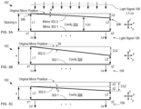
- FIGS. 2A-B depict schematic drawings of cross-sectional views of an FP-cavity-based spectral filter in accordance with the prior art in different modes of operation.
- Spectral filter 200 is a conventional FP-cavity-based device that includes parallel mirrors 202-1 and 202-2, which define optically resonant cavity 204 having a cavity length equal to the separation between the mirrors.
- the parallel nature of its mirrors enables spectral filter 200 to receive a multispectral input optical signal having a wide spectral range and pass an output optical signal containing only one narrow wavelength signal, where the spectral content of the output optical signal is uniform across the entire width of optically resonant cavity 204.
- the cavity length of spectral filter 200 is controlled, thereby enabling the wavelength signal passed by the spectral filter to be tuned over a desired tuning range.
- spectral filter 200 In a first operational mode of spectral filter 200, depicted in FIG. 2A , mirrors 202-1 and 202-2 are parallel and separated by cavity length L across the width of optically resonant cavity 204 from first location x1 to second location x2.
- the spectral filter receives input optical signal 206, which includes the spectral range from ⁇ A to ⁇ B .
- spectral filter 200 Based on its cavity length of L, spectral filter 200 passes only wavelength signal ⁇ a within the spectral range of ⁇ A to ⁇ B.
- spectral filter 200 In a second operational mode of spectral filter 200, depicted in FIG. 2B , the position of mirrors 202-1 is changed by distance ⁇ 1 such that mirrors 202-1 and 202-2 are still parallel but separated by new cavity length L' across the width of optically resonant cavity 204 from first location x1 to second location x2.
- the spectral filter passes only wavelength signal ⁇ b within the spectral range of ⁇ A to ⁇ B over the width of the optically resonant cavity.
- embodiments in accordance with the present disclosure control the angle of one of the mirrors of an FP cavity-based spectral filter relative to the plane of the other mirror of the cavity, thereby adding spectral dispersive capability to the device.
- the position and width of the spectral range passed by the spectral filter can be controlled, providing significant advantage over prior-art spectral filters.
- FIGS. 3A-C depict schematic drawings of cross-sectional views of an FP-cavity-based spectral filter in accordance with the present disclosure in different exemplary modes of operation.
- Spectral filter 102 includes planar mirrors 302-1 and 302-2, which define optically resonant cavity 304 (hereinafter referred to as "cavity 304 ”) whose cavity length is L1 when the spectral filter is in its quiescent state.
- mirror 302-2 is operatively coupled with a pair of vertical actuators, one of which is operative for controlling the height of first end 306 of mirror 302-2 at location x1, and the other of which is operative for controlling the height of second end 308 of mirror 302-2 at location x2.
- the angle of mirror 302-2 relative to mirror 302-1 can be controlled to realize a cavity length having a linear gradient, L(x), along the width of cavity 304.
- L(x) linear gradient
- FIG. 3A depicts spectral filter 102 in a first configuration wherein second end 308 has been moved toward mirror 302-1 by a distance ⁇ 2 while first end 306 remains in its quiescent position.
- mirror 302-2 is tilted at angle ⁇ relative to mirror 302-1. Since first end 306 remains in its original position, the cavity length at location x1 remains L1, while the cavity length at location x2 is reduced to L2.
- the separation between mirrors 302-1 and 302-2 is non-uniform along the width of cavity 304, the separation between them at location x1 is designated herein as spacing s. It will be appreciated by one skilled in the art that any point along cavity 304 (e.g., the separation at location x2, the spacing in the center of cavity 304, etc.) can be used as a reference for this spacing, however.
- cavity 304 Due to its cavity length of L1 at x1, cavity 304 passes wavelength signal ⁇ c of light signal 106 at location x1. In similar fashion, due to its cavity length of L2 at x2, the wavelength signal of light signal 106 passed by cavity 304 reduces to ⁇ d at location x2. From x1 to x2, cavity 304 passes a set of wavelength signals whose wavelengths decrease linearly from ⁇ c to ⁇ d according to cavity length L(x).
- FIG. 3B depicts spectral filter 102 in a second configuration wherein second end 308 has been moved toward mirror 302-1 by twice the distance as that shown in FIG. 3A (i.e., by 2 ⁇ 2 ), while first end 306 remains in its quiescent position.
- mirror 302-2 is tilted at angle 2 ⁇ relative to mirror 302-1. Since first end 306 remains in its original position, the cavity length at location x1 remains L1, while the cavity length at location x2 is decreased to L2'.
- cavity 304 passes wavelength signals within the range of ⁇ c to ⁇ e , which are spatially dispersed along the line from location x1 to location x2.
- the spectral range passed in the second configuration is twice as wide as the spectral range passed in the first configuration.
- the spectral resolution attainable in the first configuration is twice the spectral resolution in the second configuration.
- FIG. 3C depicts spectral filter 102 in a third configuration wherein second end 308 has been moved to effect a tilt of ⁇ on mirror 302-1 while also reducing the separation of the mirrors by distance ⁇ 2 ).
- the cavity length at location x1 is L2
- the cavity length at location x2 is L2'.
- cavity 304 passes wavelength signals within the range of ⁇ d to ⁇ e, which are spatially dispersed along the line from location x1 to location x2.
- embodiments in accordance with the present disclosure can control either or both of the spectral range and spectral resolution of optical output signal 108 over a wide range (subject to the limitations of the actuators used). It should be noted that, by sequentially implementing the first and third configurations described above, the spectral range obtained for light signal 108 via the second configuration can be obtained - but with twice the resolution. Furthermore, by setting the tilt angle of mirror 302-2 to realize a high-spectral resolution output over a narrow spectral range and changing the separation between mirrors 302-1 and 302-2 N times, N high-resolution sub-spectra within the spectral range of input light signal 106 can be obtained. In fact, in some embodiments, the entire spectral range of input light signal 106 can be scanned with high-resolution in such a manner by judicious selection of the tilt angle, the width of each spectral sub-range, and the value of N.
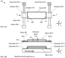
- cavity 304 includes mirrors 302-1 and 302-2, each of which is highly reflective for input optical signal 106.
- Mirror 302-1 is a stationary Bragg reflector disposed on the surface of substrate 408.
- substrate 408 is a conventional silicon substrate; however, a wide variety of materials can be used in substrate 408 without departing from the scope of the present invention.
- each of mirrors 302 is a multilayer Bragg reflector designed to realize high-reflectivity (> 99.9999%) over the entire MIR spectral range.
- Each of mirrors 302 includes a plurality of structural layers 410 having a relatively higher refractive index and a plurality of air layers that function as relatively lower-refractive index layers in the Bragg reflector structure. The structural layers and air layers alternate such that adjacent structural layers are separated by an air layer.
- each mirror includes three structural layers made of low-residual-stress amorphous silicon having a refractive index of approximately 3.5 and a thickness of approximately 785 nm (approximately 1 ⁇ 4 of the center wavelength of the MIR spectral range as measured in the material of the structural layer). Adjacent structural layers are separated by an air gap having a thickness of approximately 2.75 microns (approximately 1 ⁇ 4 of the center wavelength of the MIR spectral range in air). It should be noted that the materials and design parameters provided for mirrors 302 are merely exemplary and that myriad alternative designs for the mirrors of spectral filter 102 are within the scope of the present disclosure.
- Each of actuators 402-1 and 402-2 (referred to, collectively, as actuators 402) is a vertical electrostatic actuator that includes a fixed electrode disposed on substrate 408 and a movable electrode that is affixed to mirror 302-2.
- actuator 402-1 includes fixed electrode 412-1 and movable electrode 414-1
- actuator 402-2 includes fixed electrode 412-2 and moveable electrode 414-2.
- Actuator 402-1 controls the cavity length at location x1 based on a voltage applied between electrodes 412-1 and 414-1.
- actuator 402-2 controls the cavity length at location x2 based on a voltage applied between electrodes 412-1 and 414-1.
- an applied voltage of approximately 10 V is sufficient to fully actuate each of actuators 402-1 and 402-2.
- Electrodes 412-1 and 412-2 are regions of doped amorphous silicon that are electrically connected with substrate 408, which is connected to electrical ground. In some embodiments, electrodes 412-1 and 412-2 are electrically isolated from the substrate by layer of dielectric, such as silicon nitride, to enable them to be independently driven.
- dielectric such as silicon nitride
- Electrodes 414-1 and 414-2 are regions of doped amorphous silicon that are disposed on the bottom surface of mirror 302-2. Electrodes 414-1 and 414-2 are electrically connected to bond pads 418-1 and 418-2, respectively, via electrical traces of doped amorphous silicon that run along the underside of tethers 404.
- Tethers 404 are beams of amorphous silicon having a cross-sectional shape that substantially selectively enables flexure of the tethers out of the x-y plane, while substantially inhibiting their flexure within the x-y plane. It should be noted that, while the depicted example includes tethers that are simple straight beams, myriad tether designs can be used in spectral filter 102 without departing from the scope of the present invention. Tethers suitable for use in spectral filter 102 include, without limitation, serpentine springs, folded-beam tethers, and the like. It should be further noted that the actuation voltage required to configure spectral filter 102 is significantly affected by the design of tethers 404.
- Anchors 406 are stationary, mechanically robust projections that extend vertically from the top surface of substrate 408.
- Bond pads 418-1 and 418-2 are formed on the top of their respective anchors 406 by opening a window to the material of tethers 404 and depositing metal into the openings (typically via a shadow-mask process).
- Electrodes 414-1 and 414-2, as well as their respective traces is electrically isolated from the structural material of mirror 302-2 via a thin layer of dielectric 416 so that each of electrodes 414-1 and 414-2 can be individually addressed.
- dielectric 416 is silicon nitride, which is substantially unaffected by the etchant used to release mirror 302-2 from substrate 408, as discussed below.
- actuators 402-1 and 402-2 and their arrangement in spectral filter 102, represents merely one example of a suitable actuation scheme for the spectral filter.
- Suitable alternative actuation includes vertical comb-drive actuators (which could be disposed on either sides of mirror 302-2, or elsewhere), rotary comb-drive actuators (disposed at the center of the top and bottom edges, or disposed at either side, of mirror 302-2), thermal actuators, magnetostrictive actuators, non-micromechanical actuators, and the like.
- spectral filters that disperse the spectral content of their output optical signals along two lateral directions, such as the x- and y-directions.
- one or more additional actuators arranged along the y-direction can be used.
- two-axis gimbal structures such as those used for two-axis beam-steering mirrors known in the prior art, can be employed to provide two-dimensional orientation control of mirror 302-2.
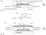
- FIGS. 5A-B depict schematic drawings of cross-sectional views of spectral filter 102 at different stages of its fabrication in accordance with the illustrative embodiment.
- the method described herein employs conventional surface micromachining processes developed within the Micro Electro Mechanical Systems (MEMS) technology realm.
- MEMS Micro Electro Mechanical Systems
- spectral filter 102 begins with formation of a layer of doped, low-residual stress amorphous silicon on the top surface of substrate 408. This layer is then patterned to define the first structural layer 410 in mirror 302-1, as well as electrodes 412-1 and 412-2.
- sacrificial layers 502 comprise borophosphosilicate glass (BPSG) and structural layers 410 comprise doped, low-residual stress amorphous silicon.
- BPSG borophosphosilicate glass
- structural layers 410 comprise doped, low-residual stress amorphous silicon.
- the layer structure of sacrificial and structural layers defines the nascent Bragg reflector stack of mirror 302-1.
- Sacrificial layer 504 is then formed over the entire surface of the substrate to encase mirror 302-1 and electrodes 412-1 and 412-2 in sacrificial material.
- FIG. 5A depicts a cross-sectional view of nascent spectral filter 102 after formation of sacrificial layer 504.
- Sacrificial layer 504 is then patterned to define pedestals 508, which function as the core of anchors 406.
- the first (bottom-most) structural layer 410 of mirror 302-2 is then formed on surface 506 and over pedestals 508. This structural layer is then patterned to define the bottom-most layer of mirror 302-2, electrodes 414-1 and 414-2 and their respective traces, and outer shell 510 of anchors 406.
- FIG. 5B depicts a cross-sectional view of an anchor 406 after formation of the first structural layer 410 of mirror 302-2.
- Successive deposition and patterning of sacrificial layers 502 and structural layers 410 is then performed again to complete the nascent Bragg reflector stack of mirror 302-2, as well as tethers 406.
- FIG. 5C depicts a cross-sectional view of nascent spectral filter 102 after formation of the layer structure of mirror 302-2.
- nascent structure of spectral filter 102 is then completed by forming vias to expose the top surface of shell 510 for the anchors that are electrically connected to electrodes 414-1 and 414-2.
- nascent filter 102 is subjected to a release etch in hydrofluoric acid to remove all regions of sacrificial material 502 except for pedestals 508, which are protected from attack by shells 510.
- metal is deposited using a shadow-mask deposition to form bond pads 418-1 and 418-2.
- spectral filter 502 materials and structure of spectral filter 502 are merely exemplary and that many suitable combinations of structural and sacrificial materials can be used without departing from the scope of the present invention.
- spectral filter 102 many alternative methods for forming spectral filter 102 exist within the scope of the present disclosure.
- Other exemplary methods include fabrication of each mirror structure on separate substrates and then joining the substrates to form an FP cavity.
- separate substrates comprising the mirrors are joined using a resilient material (e.g., Polydimethylsilicone (PDMS), etc.) that enables the use of mechanical force (e.g., clamping, pneumatic or hydraulic actuation, screws, etc.) to compress one or both sides of an FP cavity to induce a desired tilt and/or mirror separation.
- a resilient material e.g., Polydimethylsilicone (PDMS), etc.
- mechanical force e.g., clamping, pneumatic or hydraulic actuation, screws, etc.
- an air-layer-based Bragg reflector is formed by etching an arrangement of holes through the structural-material layers and sacrificial-material layers of at least one of nascent mirrors 302. Once the holes are formed through the layer stack, a timed sacrificial etch is used to laterally etch most, but not all, of the sacrificial material layers. As a result, when the timed etch is finished, small regions of sacrificial material remain, which function to hold the structural-material layers in their desired spatial relationship.
- the cavity length at both ends of cavity 304 can be controlled; therefore, each of the shortest and longest wavelengths in the spectral content of output optical signal 106 can be independently controlled. This affords spectral measurement methods are not practical, or in some cases, possible, using prior art hyperspectral measurement systems. Two examples of spectral measurement methods in accordance with the present disclosure are described here.
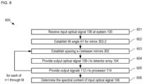
- FIG. 6 depicts operation of a first exemplary method for determining the spectral content of a light signal in accordance with the present invention.
- Method 600 is described herein with continuing reference to FIGS. 1 , 3 , and 4 .
- Method 600 begins with operation 601, wherein input optical signal 106 is received by hyperspectral detection system 100.
- input optical signal 106 spans the wavelength range from 2 microns to 20 microns.
- the quiescent cavity length of cavity 304 passes light whose wavelength is equal to 20 microns and detector array 104 includes 1000 detectors 110, which are equally spaced along the x-direction.
- mirror 302-2 is tilted by angle ⁇ 1 without changing the separation of mirrors 302 at location x1.
- the magnitude of ⁇ 1 is selected such that the spectral width of output optical signal 108 is 1 micron.
- output optical signal 108 has a spectrum that spans the wavelength range from 20.0 microns to 19.001 microns.
- spacing s- i is established to set the spectral position of the spectrum of output optical signal 108- i .
- the value of s- i is changed by an amount suitable to change the spectral position of the spectrum of output optical signal 108- i by W/M, while maintaining the tilt angle of mirror 302-2 at ⁇ 1.
- the spectrum of output signal 108 shifts to shorter wavelengths by one micron while maintaining the same spectral width.
- output optical signal 108- i is provided to detector array 104.
- detectors 110 detect wavelength signals that span the range from 20.0 microns to 19.001 microns with a spectral resolution of 1 nm.
- output signals 112- i are provided to processor 114.
- processor 114 determines the spectral content of input optical signal 106 based on output signals 112-1 through 112-M.
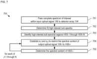
- FIG. 7 depicts operation of a second exemplary method for determining the spectral content of a light signal in accordance with the present invention.
- Method 700 is described herein with continuing reference to FIGS. 1 , 3 , and 4 .
- Method 700 enables a wide spectral range of light to be quickly measured at low resolution to identify spectral regions within it that warrant measurement at higher resolution.
- Method 700 therefore, provides a "spectral zoom" capability that enables a user to quickly identify and analyze only those portions of the larger spectrum signal that are deemed critical.
- Method 700 begins with operation 701, wherein a complete spectrum of interest within input optical signal 106 is passed by spectral filter 102 as output optical signal 108.
- the spectrum of interest is the entire MIR spectral range.
- a first, typically large, tilt angle, ⁇ 2 is established for mirror 302-2.
- processor 114 identifies N high-interest sub-spectral regions, HSS-1 through HSS-N, within the spectrum of interest based on output signals 112 from detectors 110.
- spacing s- j and tilt angle ⁇ - j are established such that the spectral content of output optical signal 106 is set to HSS- j .
- processor 114 determines the spectral content of HSS- j .
- the high-resolution measurement of at least one high-interest spectrum reveals one or more smaller spectral regions that warrant analysis with even higher spectral resolution.
- spacing s and tilt angle ⁇ can be re-established such that output optical signal 108 distributes only its spectrum across detectors 110. It should be noted that this spectral "zooming" process can be repeated until the practical limit on the control resolution of actuators 402-1 and 402-2 is reached.
- each of detectors 110 senses the same wavelength, thereby converting system 100 into a spectral-imaging camera.
- hyperspectral detection systems have found widespread use in many applications, such as hyperspectral imaging and spectroscopy.
- Embodiments of the present invention are particularly well suited for use in high-resolution spectroscopy due to the ability to operate in the MIR spectral range.
- FIG. 8 depicts a schematic drawing of a cross-sectional view of a high-resolution spectrometer in accordance with a preferred embodiment of the present invention.
- Spectrometer 800 includes spectral filter 102, detector array 104, light source 802, and sample cuvette 804.
- Light source 802 is a radiation source operative for providing light signal 106.
- Sample cuvette 804 is a chamber suitable for holding a test sample 806, which is typically a fluid such as blood, spittle, etc. In the depicted example, sample 806 is blood.
- prior-art spectrometers particularly compact spectrometers - often suffer from limited sensitivity because the material being analyzed does not absorb efficiently and the path length of light through the sample is not long enough. Longer path lengths limit miniaturization and complicate the optical filter response by allowing multiple wavelengths to resonate within the system.
- sample cuvette 804 is located in cavity 304 formed by mirrors 302-1 and 302-2.
- the absorption peaks in sample 806 are optically amplified and the geometry of system 800 enables the measurement and quantification of trace amounts of material within cavity 304. It should be noted that the amplification of the light absorption by the quality factor, Q, of cavity 304, which can easily exceed 2000, will enable the improvement of the sensitivity by this factor. Consequently, the contrast of the spectrum is markedly increased by locating sample 806 within the optical hyperspectral filtering cavity of spectral filter 102.
- cavity 304 is oriented at a non-normal angle relative to the propagation direction of input optical signal 106 (i.e., ⁇ 90°) such that both of mirrors 302 are at a non-right angle to axis A1 when the spectral filter is in its quiescent state.
- the resonant peak position of cavity 304 is shifted according to the cosine of angle ⁇ and the spectral range of light transmitted through the cavity in its quiescent state is narrowed.
- the quality factor, Q, of cavity 304 is improved, thereby markedly improving the sensitivity of spectrometer 800.
- sample 806 in the optically resonant cavity is highly advantageous, the sample can also be located between light source 802 and spectral filter 102, or between spectral filter 102 and detector array 104, without departing from the scope of the present disclosure.
Landscapes
- Physics & Mathematics (AREA)
- Spectroscopy & Molecular Physics (AREA)
- General Physics & Mathematics (AREA)
- Spectrometry And Color Measurement (AREA)
Applications Claiming Priority (3)
| Application Number | Priority Date | Filing Date | Title |
|---|---|---|---|
| US201762511504P | 2017-05-26 | 2017-05-26 | |
| US201762597223P | 2017-12-11 | 2017-12-11 | |
| PCT/US2018/034710 WO2018218179A1 (en) | 2017-05-26 | 2018-05-25 | Spectral filter having controllable spectral bandwidth and resolution |
Publications (3)
| Publication Number | Publication Date |
|---|---|
| EP3631389A1 EP3631389A1 (en) | 2020-04-08 |
| EP3631389A4 EP3631389A4 (en) | 2021-03-10 |
| EP3631389B1 true EP3631389B1 (en) | 2025-03-26 |
Family
ID=64397106
Family Applications (1)
| Application Number | Title | Priority Date | Filing Date |
|---|---|---|---|
| EP18806111.3A Active EP3631389B1 (en) | 2017-05-26 | 2018-05-25 | Spectral filter having controllable spectral bandwidth and resolution |
Country Status (6)
| Country | Link |
|---|---|
| US (1) | US10488256B2 (enExample) |
| EP (1) | EP3631389B1 (enExample) |
| JP (1) | JP2020521972A (enExample) |
| KR (1) | KR102296101B1 (enExample) |
| CN (1) | CN110914654A (enExample) |
| WO (1) | WO2018218179A1 (enExample) |
Families Citing this family (6)
| Publication number | Priority date | Publication date | Assignee | Title |
|---|---|---|---|---|
| EP3821505A4 (en) * | 2018-07-13 | 2022-07-06 | The Government of the United States of America as represented by the Secretary of the Navy | HIGH STABILITY SEMICONDUCTOR LASERS AND SENSORS FOR III-V AND SILICON PHOTONIC INTEGRATED CIRCUITS |
| WO2020163492A1 (en) * | 2019-02-06 | 2020-08-13 | California Institute Of Technology | Compact hyperspectral mid-infrared spectrometer |
| WO2021056251A1 (zh) * | 2019-09-25 | 2021-04-01 | 深圳市海谱纳米光学科技有限公司 | 一种可调光学滤波装置 |
| US11894399B2 (en) | 2021-03-02 | 2024-02-06 | Wisconsin Alumni Research Foundation | Compact hyperspectral spectrometers based on semiconductor nanomembranes |
| US12339478B2 (en) * | 2021-04-22 | 2025-06-24 | Samsung Electronics Co., Ltd. | Spectral filter, and image sensor and electronic device including spectral filter |
| FI131821B1 (en) * | 2023-10-12 | 2025-12-17 | Teknologian Tutkimuskeskus Vtt Oy | Measurement equipment, which includes a Fabry-Perot interferometer |
Family Cites Families (26)
| Publication number | Priority date | Publication date | Assignee | Title |
|---|---|---|---|---|
| US5144498A (en) * | 1990-02-14 | 1992-09-01 | Hewlett-Packard Company | Variable wavelength light filter and sensor system |
| US5056101A (en) * | 1990-09-19 | 1991-10-08 | At&T Bell Laboratories | Mode partition screening apparatus |
| US5784507A (en) * | 1991-04-05 | 1998-07-21 | Holm-Kennedy; James W. | Integrated optical wavelength discrimination devices and methods for fabricating same |
| FR2689345B1 (fr) * | 1992-03-26 | 1995-05-12 | Cit Alcatel | Filtre optique comprenant un interféromètre Fabry-Perot accordable par rotation. |
| JPH07103824A (ja) * | 1993-09-30 | 1995-04-21 | Shimadzu Corp | 分光器 |
| JP3464081B2 (ja) * | 1995-07-26 | 2003-11-05 | 富士通株式会社 | 波長分波器 |
| US6324192B1 (en) * | 1995-09-29 | 2001-11-27 | Coretek, Inc. | Electrically tunable fabry-perot structure utilizing a deformable multi-layer mirror and method of making the same |
| US6665109B2 (en) * | 2000-03-20 | 2003-12-16 | Np Photonics, Inc. | Compliant mechanism and method of forming same |
| JP2001281443A (ja) * | 2000-03-28 | 2001-10-10 | Toyo Commun Equip Co Ltd | エアーギャップ型ファブリペローエタロン |
| GB2371119A (en) | 2000-09-25 | 2002-07-17 | Marconi Caswell Ltd | Micro electro-mechanical systems |
| TW531671B (en) * | 2002-07-22 | 2003-05-11 | Delta Electronics Inc | Tunable filter applied in optical networks |
| CN1504731A (zh) * | 2002-12-03 | 2004-06-16 | 台达电子工业股份有限公司 | 法布里-珀罗装置的精度补偿方法及高精度法布里-珀罗装置 |
| GB2416427A (en) | 2004-06-18 | 2006-01-25 | Univ Sheffield | DFB laser |
| JP2008003045A (ja) * | 2006-06-26 | 2008-01-10 | Hamano Life Science Research Foundation | スペクトル測定装置およびスペクトル測定方法 |
| US7852490B2 (en) * | 2007-02-05 | 2010-12-14 | Palo Alto Research Center Incorporated | Implanting optical cavity structures |
| US7817281B2 (en) * | 2007-02-05 | 2010-10-19 | Palo Alto Research Center Incorporated | Tuning optical cavities |
| JP2009128193A (ja) * | 2007-11-22 | 2009-06-11 | Graduate School For The Creation Of New Photonics Industries | 波長センサ |
| JP2010224265A (ja) * | 2009-03-24 | 2010-10-07 | Olympus Corp | ファブリ=ペロー型可変干渉フィルタの傾斜角度制御方法 |
| DE102009021936A1 (de) * | 2009-05-19 | 2010-11-25 | Fraunhofer-Gesellschaft zur Förderung der angewandten Forschung e.V. | Optisches Filter und ein Verfahren zur Herstellung eines optischen Filters |
| JP2012154780A (ja) * | 2011-01-26 | 2012-08-16 | Jvc Kenwood Corp | 分光器 |
| CN102401996B (zh) * | 2011-11-30 | 2014-05-07 | 武汉邮电科学研究院 | 一种可调谐光滤波器的使用方法 |
| FI125690B (en) | 2013-06-18 | 2016-01-15 | Teknologian Tutkimuskeskus Vtt Oy | Mirror for Fabry-Perot interferometer and method for its manufacture |
| WO2015081130A1 (en) | 2013-11-26 | 2015-06-04 | Inphenix, Inc. | Wavelength tunable mems-fabry perot filter |
| TWI555119B (zh) | 2014-03-21 | 2016-10-21 | 力晶科技股份有限公司 | 具有氣隙的結構的形成方法 |
| US9677935B2 (en) * | 2014-11-03 | 2017-06-13 | Trutag Technologies, Inc. | Fabry-perot spectral image measurement |
| US10850974B2 (en) | 2015-05-05 | 2020-12-01 | The University Of Western Australia | Microelectromechanical systems (MEMS) and methods |
-
2018
- 2018-05-25 EP EP18806111.3A patent/EP3631389B1/en active Active
- 2018-05-25 US US15/990,114 patent/US10488256B2/en active Active
- 2018-05-25 JP JP2019565398A patent/JP2020521972A/ja active Pending
- 2018-05-25 KR KR1020197038177A patent/KR102296101B1/ko active Active
- 2018-05-25 WO PCT/US2018/034710 patent/WO2018218179A1/en not_active Ceased
- 2018-05-25 CN CN201880046030.2A patent/CN110914654A/zh active Pending
Also Published As
| Publication number | Publication date |
|---|---|
| JP2020521972A (ja) | 2020-07-27 |
| KR102296101B1 (ko) | 2021-08-30 |
| EP3631389A4 (en) | 2021-03-10 |
| EP3631389A1 (en) | 2020-04-08 |
| WO2018218179A1 (en) | 2018-11-29 |
| CN110914654A (zh) | 2020-03-24 |
| US20180340826A1 (en) | 2018-11-29 |
| KR20200014808A (ko) | 2020-02-11 |
| US10488256B2 (en) | 2019-11-26 |
Similar Documents
| Publication | Publication Date | Title |
|---|---|---|
| EP3631389B1 (en) | Spectral filter having controllable spectral bandwidth and resolution | |
| EP2816389B1 (en) | A method for producing a mirror for a Fabry-Perot interferomete | |
| US7734131B2 (en) | Fabry-Perot tunable filter using a bonded pair of transparent substrates | |
| EP3839454B1 (en) | Polarization spectral filter, polarization spectral filter array, and polarization spectral sensor | |
| EP3268708B1 (en) | A mirror plate for a fabry-perot interferometer and a fabry-perot interferometer | |
| US11460607B2 (en) | Dynamic filter comprising a first and second metasurface for spectral sensing and emitting systems | |
| EP3485243A1 (en) | Miniaturized waveguide imaging spectrometer | |
| Antila et al. | MEMS and piezo actuator-based Fabry-Perot interferometer technologies and applications at VTT | |
| Zimmer et al. | Development of a NIR microspectrometer based on a MOEMS scanning grating | |
| Shi et al. | MEMS-based filter integrating tunable Fabry–Perot cavity and grating | |
| EP2026051B1 (en) | Spectroscopy device, spectroscopy apparatus and spectroscopy method | |
| CA3045981C (en) | Spectrometer, analysis equipment, and wavelength-variable light source | |
| Meinig et al. | Tunable Fabry-Pérot interferometer with subwavelength grating reflectors for MWIR microspectrometers | |
| JP7200658B2 (ja) | 光学装置、及び電子機器 | |
| US20100220331A1 (en) | Micro-electromechanical system fabry-perot filter cavity | |
| EP3444578B1 (en) | Method and system for analysing a chemical composition of a target | |
| Gruger et al. | Performance and applications of a spectrometer with micromachined scanning grating | |
| EP4176238B1 (en) | Fourier transform spectrometer and method of fourier transform spectroscopy | |
| Bannik et al. | Micromachined Double‐Membrane Mechanically Tunable Metamaterial for Thermal Infrared Filtering | |
| Li et al. | Micro/Nanoscale Optical Devices for Hyperspectral Imaging System | |
| WO2018135223A4 (en) | Spectrometer, analysis equipment, and wavelength-variable light source | |
| Sahani et al. | Simultaneous Imaging and Spectroscopy with Pixelized Gradient Thickness Optical Filter | |
| Srivastava et al. | Microfabricated interferometer and integrated fluidic channel for infrared spectroscopy of aqueous samples | |
| Kemme et al. | Pixelated spectral filter for integrated focal plane array in the long-wave IR | |
| WO2024263769A1 (en) | Volumetric silicon meta-optics for compact and low-power terahertz spectrometers |
Legal Events
| Date | Code | Title | Description |
|---|---|---|---|
| STAA | Information on the status of an ep patent application or granted ep patent |
Free format text: STATUS: THE INTERNATIONAL PUBLICATION HAS BEEN MADE |
|
| PUAI | Public reference made under article 153(3) epc to a published international application that has entered the european phase |
Free format text: ORIGINAL CODE: 0009012 |
|
| STAA | Information on the status of an ep patent application or granted ep patent |
Free format text: STATUS: REQUEST FOR EXAMINATION WAS MADE |
|
| 17P | Request for examination filed |
Effective date: 20191111 |
|
| AK | Designated contracting states |
Kind code of ref document: A1 Designated state(s): AL AT BE BG CH CY CZ DE DK EE ES FI FR GB GR HR HU IE IS IT LI LT LU LV MC MK MT NL NO PL PT RO RS SE SI SK SM TR |
|
| AX | Request for extension of the european patent |
Extension state: BA ME |
|
| DAV | Request for validation of the european patent (deleted) | ||
| DAX | Request for extension of the european patent (deleted) | ||
| A4 | Supplementary search report drawn up and despatched |
Effective date: 20210210 |
|
| RIC1 | Information provided on ipc code assigned before grant |
Ipc: G01J 3/28 20060101ALI20210204BHEP Ipc: G01J 3/26 20060101AFI20210204BHEP |
|
| STAA | Information on the status of an ep patent application or granted ep patent |
Free format text: STATUS: EXAMINATION IS IN PROGRESS |
|
| 17Q | First examination report despatched |
Effective date: 20230329 |
|
| GRAP | Despatch of communication of intention to grant a patent |
Free format text: ORIGINAL CODE: EPIDOSNIGR1 |
|
| STAA | Information on the status of an ep patent application or granted ep patent |
Free format text: STATUS: GRANT OF PATENT IS INTENDED |
|
| INTG | Intention to grant announced |
Effective date: 20241017 |
|
| GRAS | Grant fee paid |
Free format text: ORIGINAL CODE: EPIDOSNIGR3 |
|
| GRAA | (expected) grant |
Free format text: ORIGINAL CODE: 0009210 |
|
| STAA | Information on the status of an ep patent application or granted ep patent |
Free format text: STATUS: THE PATENT HAS BEEN GRANTED |
|
| AK | Designated contracting states |
Kind code of ref document: B1 Designated state(s): AL AT BE BG CH CY CZ DE DK EE ES FI FR GB GR HR HU IE IS IT LI LT LU LV MC MK MT NL NO PL PT RO RS SE SI SK SM TR |
|
| REG | Reference to a national code |
Ref country code: GB Ref legal event code: FG4D |
|
| REG | Reference to a national code |
Ref country code: CH Ref legal event code: EP |
|
| REG | Reference to a national code |
Ref country code: DE Ref legal event code: R096 Ref document number: 602018080505 Country of ref document: DE |
|
| REG | Reference to a national code |
Ref country code: IE Ref legal event code: FG4D |
|
| PG25 | Lapsed in a contracting state [announced via postgrant information from national office to epo] |
Ref country code: RS Free format text: LAPSE BECAUSE OF FAILURE TO SUBMIT A TRANSLATION OF THE DESCRIPTION OR TO PAY THE FEE WITHIN THE PRESCRIBED TIME-LIMIT Effective date: 20250626 |
|
| PG25 | Lapsed in a contracting state [announced via postgrant information from national office to epo] |
Ref country code: FI Free format text: LAPSE BECAUSE OF FAILURE TO SUBMIT A TRANSLATION OF THE DESCRIPTION OR TO PAY THE FEE WITHIN THE PRESCRIBED TIME-LIMIT Effective date: 20250326 |
|
| PGFP | Annual fee paid to national office [announced via postgrant information from national office to epo] |
Ref country code: DE Payment date: 20250529 Year of fee payment: 8 |
|
| PGFP | Annual fee paid to national office [announced via postgrant information from national office to epo] |
Ref country code: GB Payment date: 20250602 Year of fee payment: 8 |
|
| REG | Reference to a national code |
Ref country code: LT Ref legal event code: MG9D |
|
| PG25 | Lapsed in a contracting state [announced via postgrant information from national office to epo] |
Ref country code: NO Free format text: LAPSE BECAUSE OF FAILURE TO SUBMIT A TRANSLATION OF THE DESCRIPTION OR TO PAY THE FEE WITHIN THE PRESCRIBED TIME-LIMIT Effective date: 20250626 |
|
| PG25 | Lapsed in a contracting state [announced via postgrant information from national office to epo] |
Ref country code: HR Free format text: LAPSE BECAUSE OF FAILURE TO SUBMIT A TRANSLATION OF THE DESCRIPTION OR TO PAY THE FEE WITHIN THE PRESCRIBED TIME-LIMIT Effective date: 20250326 |
|
| PG25 | Lapsed in a contracting state [announced via postgrant information from national office to epo] |
Ref country code: LV Free format text: LAPSE BECAUSE OF FAILURE TO SUBMIT A TRANSLATION OF THE DESCRIPTION OR TO PAY THE FEE WITHIN THE PRESCRIBED TIME-LIMIT Effective date: 20250326 |
|
| PGFP | Annual fee paid to national office [announced via postgrant information from national office to epo] |
Ref country code: FR Payment date: 20250526 Year of fee payment: 8 |
|
| PG25 | Lapsed in a contracting state [announced via postgrant information from national office to epo] |
Ref country code: GR Free format text: LAPSE BECAUSE OF FAILURE TO SUBMIT A TRANSLATION OF THE DESCRIPTION OR TO PAY THE FEE WITHIN THE PRESCRIBED TIME-LIMIT Effective date: 20250627 Ref country code: BG Free format text: LAPSE BECAUSE OF FAILURE TO SUBMIT A TRANSLATION OF THE DESCRIPTION OR TO PAY THE FEE WITHIN THE PRESCRIBED TIME-LIMIT Effective date: 20250326 |
|
| REG | Reference to a national code |
Ref country code: NL Ref legal event code: MP Effective date: 20250326 |
|
| PG25 | Lapsed in a contracting state [announced via postgrant information from national office to epo] |
Ref country code: NL Free format text: LAPSE BECAUSE OF FAILURE TO SUBMIT A TRANSLATION OF THE DESCRIPTION OR TO PAY THE FEE WITHIN THE PRESCRIBED TIME-LIMIT Effective date: 20250326 |
|
| PG25 | Lapsed in a contracting state [announced via postgrant information from national office to epo] |
Ref country code: SE Free format text: LAPSE BECAUSE OF FAILURE TO SUBMIT A TRANSLATION OF THE DESCRIPTION OR TO PAY THE FEE WITHIN THE PRESCRIBED TIME-LIMIT Effective date: 20250326 |
|
| REG | Reference to a national code |
Ref country code: AT Ref legal event code: MK05 Ref document number: 1779374 Country of ref document: AT Kind code of ref document: T Effective date: 20250326 |
|
| PG25 | Lapsed in a contracting state [announced via postgrant information from national office to epo] |
Ref country code: SM Free format text: LAPSE BECAUSE OF FAILURE TO SUBMIT A TRANSLATION OF THE DESCRIPTION OR TO PAY THE FEE WITHIN THE PRESCRIBED TIME-LIMIT Effective date: 20250326 |
|
| PG25 | Lapsed in a contracting state [announced via postgrant information from national office to epo] |
Ref country code: ES Free format text: LAPSE BECAUSE OF FAILURE TO SUBMIT A TRANSLATION OF THE DESCRIPTION OR TO PAY THE FEE WITHIN THE PRESCRIBED TIME-LIMIT Effective date: 20250326 Ref country code: PT Free format text: LAPSE BECAUSE OF FAILURE TO SUBMIT A TRANSLATION OF THE DESCRIPTION OR TO PAY THE FEE WITHIN THE PRESCRIBED TIME-LIMIT Effective date: 20250728 |
|
| PG25 | Lapsed in a contracting state [announced via postgrant information from national office to epo] |
Ref country code: PL Free format text: LAPSE BECAUSE OF FAILURE TO SUBMIT A TRANSLATION OF THE DESCRIPTION OR TO PAY THE FEE WITHIN THE PRESCRIBED TIME-LIMIT Effective date: 20250326 Ref country code: IT Free format text: LAPSE BECAUSE OF FAILURE TO SUBMIT A TRANSLATION OF THE DESCRIPTION OR TO PAY THE FEE WITHIN THE PRESCRIBED TIME-LIMIT Effective date: 20250326 |
|
| PG25 | Lapsed in a contracting state [announced via postgrant information from national office to epo] |
Ref country code: AT Free format text: LAPSE BECAUSE OF FAILURE TO SUBMIT A TRANSLATION OF THE DESCRIPTION OR TO PAY THE FEE WITHIN THE PRESCRIBED TIME-LIMIT Effective date: 20250326 |
|
| PG25 | Lapsed in a contracting state [announced via postgrant information from national office to epo] |
Ref country code: EE Free format text: LAPSE BECAUSE OF FAILURE TO SUBMIT A TRANSLATION OF THE DESCRIPTION OR TO PAY THE FEE WITHIN THE PRESCRIBED TIME-LIMIT Effective date: 20250326 |
|
| PG25 | Lapsed in a contracting state [announced via postgrant information from national office to epo] |
Ref country code: RO Free format text: LAPSE BECAUSE OF FAILURE TO SUBMIT A TRANSLATION OF THE DESCRIPTION OR TO PAY THE FEE WITHIN THE PRESCRIBED TIME-LIMIT Effective date: 20250326 |
|
| PG25 | Lapsed in a contracting state [announced via postgrant information from national office to epo] |
Ref country code: SK Free format text: LAPSE BECAUSE OF FAILURE TO SUBMIT A TRANSLATION OF THE DESCRIPTION OR TO PAY THE FEE WITHIN THE PRESCRIBED TIME-LIMIT Effective date: 20250326 |
|
| PG25 | Lapsed in a contracting state [announced via postgrant information from national office to epo] |
Ref country code: IS Free format text: LAPSE BECAUSE OF FAILURE TO SUBMIT A TRANSLATION OF THE DESCRIPTION OR TO PAY THE FEE WITHIN THE PRESCRIBED TIME-LIMIT Effective date: 20250726 |
|
| REG | Reference to a national code |
Ref country code: CH Ref legal event code: H13 Free format text: ST27 STATUS EVENT CODE: U-0-0-H10-H13 (AS PROVIDED BY THE NATIONAL OFFICE) Effective date: 20251223 |