EP3630497B1 - Machine de découpe de coins arrondis améliorée pour cahiers d'exercice - Google Patents
Machine de découpe de coins arrondis améliorée pour cahiers d'exercice Download PDFInfo
- Publication number
- EP3630497B1 EP3630497B1 EP18735422.0A EP18735422A EP3630497B1 EP 3630497 B1 EP3630497 B1 EP 3630497B1 EP 18735422 A EP18735422 A EP 18735422A EP 3630497 B1 EP3630497 B1 EP 3630497B1
- Authority
- EP
- European Patent Office
- Prior art keywords
- sucker
- books
- book
- corner cutting
- round corner
- Prior art date
- Legal status (The legal status is an assumption and is not a legal conclusion. Google has not performed a legal analysis and makes no representation as to the accuracy of the status listed.)
- Active
Links
- 238000005520 cutting process Methods 0.000 title claims description 57
- 241000252254 Catostomidae Species 0.000 claims description 32
- 238000000926 separation method Methods 0.000 claims description 18
- 230000007246 mechanism Effects 0.000 claims description 14
- 238000005192 partition Methods 0.000 claims description 11
- 238000000034 method Methods 0.000 claims description 4
- 230000000712 assembly Effects 0.000 description 4
- 238000000429 assembly Methods 0.000 description 4
- 238000006073 displacement reaction Methods 0.000 description 2
- 208000027418 Wounds and injury Diseases 0.000 description 1
- 230000004075 alteration Effects 0.000 description 1
- 238000010276 construction Methods 0.000 description 1
- 230000006378 damage Effects 0.000 description 1
- 238000010586 diagram Methods 0.000 description 1
- 208000014674 injury Diseases 0.000 description 1
- 238000004519 manufacturing process Methods 0.000 description 1
- 230000004048 modification Effects 0.000 description 1
- 238000012986 modification Methods 0.000 description 1
- 230000008569 process Effects 0.000 description 1
- 238000006467 substitution reaction Methods 0.000 description 1
Images


Classifications
-
- B—PERFORMING OPERATIONS; TRANSPORTING
- B42—BOOKBINDING; ALBUMS; FILES; SPECIAL PRINTED MATTER
- B42C—BOOKBINDING
- B42C19/00—Multi-step processes for making books
- B42C19/08—Conveying between operating stations in machines
-
- B—PERFORMING OPERATIONS; TRANSPORTING
- B42—BOOKBINDING; ALBUMS; FILES; SPECIAL PRINTED MATTER
- B42C—BOOKBINDING
- B42C5/00—Preparing the edges or backs of leaves or signatures for binding
- B42C5/02—Preparing the edges or backs of leaves or signatures for binding by rounding or backing
Definitions
- the present invention relates to a round corner cutting machine for exercise note books and more particularly, it relate to an improved round corner cutting machine that is configured to accommodate numbers of sharp cornered books of different size and to round corner cutting of accommodated sharp cornered bound instruction books.
- books are manufactured with sharp corner. Said sharp cornered products may hurt if it is not properly handled by the user. Hence, from the safety point of view, it is required to make it round corner to avoid injury occurred during improper handling.
- the main object of present invention is to provide an improved round corner cutting machine that performs round corner cutting of the books by overcoming the limitations associated with conventional machines.
- Another object of the present invention is to provide an improved corner cutting machine that comprises a simplified mechanism for separating the books from one another from their side edges.
- Further object of the present invention is to provide an improved round corner cutting machine that has simplified mechanism for adjustment to accommodate different size of books.
- One more object of the present invention is to provide an improved round corner cutting machine that is capable of performing round corner cutting of the multiple books simultaneously.
- the present invention relates to an improved round corner cutting machine according to claim 1 and a method according to claim 10.
- the round corner cutting machine according to present invention is described herein by implying that said machine installed in the reel to book binding machine. However, it is within the scope of present invention to utilize said machine independently. It is to be also noted that, in the drawing, identical reference number identify similar element and acts.
- book binding machine the numbers of sharp cornered books (i.e. 3 ups, 4 ups, 5 ups etc.) are prepared and conveyed towards the round corner cutting operation. Initially, said sharp cornered books are adjacent to each other at their edges. Hence, to accommodate said books, these books are required to be separated from the partition line (B) (shown in Fig. 4a, 4b, 4c ).
- the round corner cutting machine according to present invention is configured to perform separation of books as well as round corner cutting of the separated books.
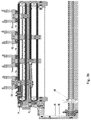
- the round corner cutting machine mainly comprises a books separator sucker assembly (1) to separate out the adjacent sharp cornered books from partition line (B) for easy entry into next unit, a book gripper assembly (2) configured for griping and placing sharp cornered book onto the book separator sucker assembly (1) and conveying the books towards next unit after separation of books, a book stopper assembly (3) ( Fig. 2 ) for adjusting the position of the separated book and a corner cutting assembly (4) for performing corner cutting of separated books.
- Fig. 3 illustrates the diagrams for comprehensive view of the book separator sucker assembly (1).
- said book separator sucker assembly (1) comprises linearly arranged T-shaped linear guide sucker mounting blocks (100, 101, 102, 103), a cam operated lever (104) being connected to a cam shaft (105) through an eccentric bracket (106), extendable connecting links (107, 108), the length of each said link (107, 108) is adjusted by loosing bolts (107a, 108a), one end of each said connecting link (107, 108) is connected to the lever (104) at point (PI, P2) respectively and another end of each link (107, 108) is respectively connected to the guide blocks (100, 101) through bolts (109), said guide blocks (100) and (103) are connected with each other and the guide blocks (101) and (102) are connected with each other through chain sprocket mechanisms (110) and (111) respectively.
- Said eccentric bracket (106) comprises a centre hole (106a) and a side hole (106b).
- Said cam shaft follower (105) is connected with the eccentric block (106) at its end through the side hole (106b) and the lever (104) is connected with the bock (106) at its one end through the center hole (106a).
- Said eccentric bracket (106) is rotated with respect to the side center (106b) along with the rotation of cam shaft (105).
- a distance (A) between the centre hole (106a) and the side hole (106b) is configured in accordance with displacement of the guide blocks (100, 101, 102, 103) during separation of books.
- each said guide bock (100, 101, 102, 103) is configured with two extended adjustment slots (112).
- a sucker cup (113) is fastened on both sides of flat surface of each T shaped guide block through a fastening means (114) so that each guide block is connected with pair of sucker cup (113).
- FIG. 3a and 3b there is shown 4 sets (4 pairs) of sucker cups (113) and each guide block is coupled with pair of sucker cup (113).
- Said fastening means (114) is extended from the sucker cup (113) through the adjustable hole (112) and is secured at its end through a bolt (114a) so that each said guide block (100, 101, 102, 103) is anchored with the pair of sucker cup (113) as shown in Fig. 3c . Further, said suckers cups (113) are slidably supported through bars (115). For smooth sliding of said sucker cups on the bar, bearings or bushes are utilized. Each said sucker cup (113) is equipped with a sucker (116) which is connected to the vacuum pump (not shown) through valve and said valve maintain the on/off of vacuum.
- each guide block (100, 101, 102, 103) is connected with a pair of sucker (116) as shown in Fig. 3a and 3b .
- each pairs of sucker (116) grips a single book by generating vacuum therein through the vacuum pump during separating process.
- one extra middle sucker cup (113) with a sucker (116) is mounted on the bar (115) with respect to centre line (C) such that it divides equal pairs of sucker cup (113) at it's both the side.
- Said middle sucker cup (113) is operated to grip the middle book in position in case of separation of odd numbers (i.e. 3 and 5) of book.
- vacuum connection of the middle sucker (116) is disconnected.
- the distance between two paired sucker cups (113) is adjusted by sliding the sucker cups (113) in the adjustment hole (112) by losing the bolt (114a) such that one book having 2 number of suckers (116) and after adjusting the position of the sucker cups (113), said bolt (114a) is tighten.
- the position of guide blocks (100, 101, 102, 103) are also required to be set.
- the length of said links (107, 108) is adjusted by loosing the bolts (107a, 108a) and also a bolt (109) is loosen for sliding the guide blocks (100, 101, 102, 103) till one book is having pair of sucker (116) and once such position of each guide block is achieved, said bolts are secured.
- the pairs of sucker cups (113) and hence pairs of suckers (116) connected with corresponding guide blocks are also slide along the bars (115) so that the books gripped by said suckers are also separated from their partition line along with separation of pairs of suckers.
- the position of pair of suckers (116) such that each book is gripped by pair of suckers (116).
- the position of suckers (116) and guide blocks (100, 101, 102, 103) can easily be adjusted according to the size of books to be accommodated.
- the numbers of books to be accommodated can also be increased.
- the middle sucker (116) is fixedly supported through the bar (115).
- Said book stopper assembly (3) comprises a back stopper (301), at each back stopper (301) the separated book is stopped, a front jogger cam (302) ( Fig. 1 ) and a side jogger cam (not shown) for adjusting and positioning the books accurately once the book is stopped at the back stopper (301) so that the corner cutting operation is accurately carried out.
- a front jogger cam (302) Fig. 1
- a side jogger cam not shown
- Said corner cutting assembly (4) comprises a top movable knife (401) ( Fig. 2 ) and a bottom stationary knife (not shown) for performing corner cutting operation on the book.
- the product (book) is sensed by sensing means that actuate the corner cutting assembly (4).
- a book holder (402) ( Fig. 2 ) holds the book and the corner cutting of book is carried out by said top and bottom knife.
- the radius of corner cutting portion of the book can be changed by changing the top and bottom knife. According to the numbers of books to be accommodated, such corner cutting assemblies are linearly arranged such that corner cutting of each book is done by the single corner cutting assembly (4).
- the corner cutting machine is configured to accommodate 3, 4, and 5 no. of books.
- the positions of pair of suckers (116) and the guide blocks (100, 101, 102, 103) are pre-adjusted according to the size and numbers of books such that each book is positioned on pair of suckers (116) except that in case of separation of odd numbers of book, the middle book will be placed on the middle sucker.
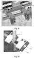
- first mode as shown in Fig. 4a , four numbers of books are linearly conveyed towards pairs of sucker (116) through their corresponding book griping assemblies (2). Said book gripping assemblies (2) will place the sharp cornered books on the suckers (116) such that each book is placed on the pair of suckers (116).
- vacuum is generated in each sucker (116) by the vacuum pump so that each pair of sucker (116) grip and hold a single book.
- the cam operated lever (104) is operated through the cam shaft (105).
- Said lever (104) will linearly move each guide block (100, 101, 102, 103) by using connecting links (107, 108) and said chain sprocket mechanism (110, 111).
- each pair of sucker cups (113) and hence the pair suckers (116) will also be moved linearly.
- the pairs of suckers (116) are separated from each other whereby the books gripped/sucked by said pairs are also separated from their partition line (B) as shown in Fig. 4a .
- the vacuum connection of the middle sucker (116) is kept in OFF condition.
- the book grippers (2) remain in OFF condition and after separation, said gripping assembly (2) grips the corresponding books again and feed the book towards the back stopper (301).
- Said lever (104) will linearly move said guide blocks (100, 101, 102, 103) with respect to each other by using the connecting links (107, 108) and the chain sprocket mechanism (110, 111).
- each pair of sucker cups (113) and hence the pair of suckers (116) will also travel.
- the pairs of suckers (116) are separated from each other whereby the books gripped/sucked by said pairs are also separated from their partition line (B).
- the middle sucker (116) will remain stationary and only pairs of sucker (116) will be moved so that the books are separated from their partition line (B) as shown in Fig. 4b .
- the vacuum is disconnected and pressurized air will allow book to move inside the back stopper assembly (3).
- each pair of sucker (116) takes it original position for receiving next set of books.
- Said gripping assembly (2) conveys the separated book towards the back stopper assembly (3) where the book is properly positioned by the front jogger cam (302) and the side jogger cam.
- corner cutting of the books is carried by corner cutting assembly (4) so that multiple numbers of books are converted into round cornered mode simultaneously.
- the round corner cutting machine according to the present invention is configured by simplified mechanism to accommodate different size and number of books for performing the corner cutting operation.
Landscapes
- Engineering & Computer Science (AREA)
- Mechanical Engineering (AREA)
- Sheets, Magazines, And Separation Thereof (AREA)
- Making Paper Articles (AREA)
Claims (10)
- Une machine de coupe en coins arrondis améliorée qui est configurée pour accueillir et séparer des livres d'instructions reliés à coins aigus de différentes tailles qui sont linéairement adjacents les uns aux autres au niveau d'une de ligne de partage (B) et pour couper en coins arrondis des livres à coins aigus accueillis et séparés, caractérisé en ce qu'elle comprend :un assemblage ventouse séparateur de livres (1) pour accueillir et séparer les livres à coins aigus adjacents de leur ligne de partage (B), un assemblage de serrage de livre (2) configuré pour serrer le livre le long d'un bord latéral et transporter les livres vers l'assemblage séparateur de livres (1) et un assemblage butée arrière (3), l'assemblage butée arrière (3) pour ajuster la position du livre à coins aigus séparé et un assemblage de coupe de coins (4) pour réaliser une opération de coupe de coins sur les livres à coins aigus positionnés par l'assemblage butée de livre (3) ;dans laquelle ledit assemblage ventouse séparateur de livres (1) comprend des blocs de guidage linéaires de montage sur ventouse agencés linéairement (100, 101, 102, 103), un levier actionné par came (104) étant connecté à un arbre de came (105) par le biais d'un support excentrique (106), des liaisons de connexion (107, 108), des paires de cuvettes de ventouse (113) pour serrer des livres, une cuvette de ventouse du milieu (113) positionnée sur une ligne centrale (C) de telle sorte qu'elle divise des nombres égaux de paires de cuvettes de ventouse (113) au niveau de ses deux côtés et maintient le livre du milieu en cas de nombres impairs de livres à séparer, une extrémité de chaque liaison de connexion (107, 108) est connectée au levier (104) et une autre extrémité de chaque dite liaison de connexion (107, 108) est connectée respectivement aux blocs de guidage (100, 101) par le biais de boulons (109) ;dans laquelle chaque dit bloc de guidage (100, 101, 102, 103) est configuré avec deux fentes d'ajustement étendues (112), chaque dit bloc de guidage (100, 101, 102, 103) est connecté à la paire de cuvettes de ventouse (113) en assujettissant la cuvette de ventouse (113) à travers la fente d'ajustement (112) par des moyens d'assujettissement (114) ;dans laquelle chaque cuvette de ventouse (113) est équipée d'une ventouse (116) pour serrer les livres ;dans laquelle la distance entre les ventouses (116) de chaque paire est ajustée en desserrant les moyens d'assujettissement (114) et en faisant coulisser les cuvettes de ventouse (113) à l'intérieur des fentes d'ajustement (112) ;dans laquelle chaque paire de ventouses (116) serre au moins un livre ;dans laquelle lesdits blocs de guidage (100) et (103) sont déplacés de façon équidistante dans une direction opposée par rapport à la ligne centrale (C) ;dans laquelle lesdits blocs de guidage (101) et (102) sont déplacés de façon équidistante dans une direction opposée par rapport à la ligne centrale (C) ;dans laquelle chaque paire de ventouses (116) se meut au fil du déplacement de blocs de guidage correspondants (100, 101, 102, 103) par le biais du levier actionné par came (104) de sorte que les livres sont séparés de leur ligne de partage (B) au fil de la séparation des paires de ventouses (116).
- La machine de coupe en coins arrondis améliorée telle que revendiquée dans la revendication 1, dans laquelle lesdites paires de cuvettes de ventouse (113) sont soutenues de façon coulissante par le biais de barres (115).
- La machine de coupe en coins arrondis améliorée telle que revendiquée dans la revendication 1, dans laquelle lesdites liaisons de connexion (107, 108) sont extensibles, grâce à quoi la position desdits blocs de guidage (100, 101, 102, 103) est ajustée par ajustement de la longueur des liaisons (107, 108) en desserrant des boulons (107a, 108a) et des boulons (109).
- La machine de coupe en coins arrondis améliorée telle que revendiquée dans la revendication 1, dans laquelle chaque ventouse (116) est connectée à un moyen généré sous vide.
- La machine de coupe en coins arrondis améliorée telle que revendiquée dans la revendication 1, dans laquelle ladite cuvette de ventouse du milieu (113) est fermement assujettie sur la barre (115).
- La machine de coupe en coins arrondis améliorée telle que revendiquée dans la revendication 1, dans laquelle ledit assemblage butée de livre (3) comprend un moyen pour ajuster la position du livre.
- La machine de coupe en coins arrondis améliorée telle que revendiquée dans la revendication 1, dans laquelle lesdits blocs de guidage (100) et (103) sont connectés l'un à l'autre et les blocs de guidage (101) et (102) sont connectés l'un à l'autre par le biais d'un mécanisme de pignon à chaîne (110) et (111) respectivement.
- La machine de coupe en coins arrondis améliorée telle que revendiquée dans la revendication 1, dans laquelle tous les blocs de guidage (100, 101, 102, 103) sont connectés les uns aux autres par le biais du mécanisme de pignon à chaîne.
- Un procédé pour couper en coins arrondis des livres d'instructions reliés à coins aigus avec une machine de coupe en coins arrondis améliorée comprenant les étapes suivantes :a) ajuster la position du bloc de guidage (100, 101, 102, 103) par le biais des liaisons de connexion (107, 108) ;b) ajuster la position des cuvettes de ventouse (113) de chaque paire à l'intérieur de la fente d'ajustement (112) des blocs de guidage (100, 101, 102, 103) de telle sorte que chaque livre soit serré par la paire de ventouses (116) ;c) transporter et placer le livre à coins aigus adjacent sur chaque paire de ventouses (116) ;d) serrer les livres en position en générant un vide dans les ventouses (116) ;e) actionner le levier actionné par came (104) par le biais de l'arbre de came (105) ;f) déplacer les blocs de guidage (100, 101) dans une direction linéaire par le biais des liaisons de liaison (107, 108) au fil du déplacement vers le haut et vers le bas du levier (104) ;g) déplacer le bloc de guidage (103) dans une direction linéaire opposée par rapport au déplacement du bloc (100) par le biais du mécanisme de pignon à chaîne (110) ;h) déplacer le bloc de guidage (102) dans une direction linéaire opposée par rapport au déplacement du bloc (101) par le biais du mécanisme de pignon à chaîne (111) ;i) déplacer chaque paire de ventouses (116) conjointement au fil du déplacement de son bloc de guidage correspondant (100, 101, 102, 103) ;j) séparer les livres de leur ligne de partage (B) au fil du déplacement des paires de ventouses (116) ;k) déconnecter le vide dans chaque paire de ventouses (116) et positionner chaque paire de ventouses (116) pour recevoir un ensemble suivant de livres adjacents ;l) transporter les livres séparés vers l'assemblage butée de livre (3) et ajuster chaque livre dans la bonne position par le biais de l'assemblage butée de livre (3) ;m) couper le coin de chaque livre en mode coin arrondi par l'assemblage de coupe de coin (4).
- Le procédé est revendiqué dans la revendication 9, dans lequel l'étape d), générer un vide dans la ventouse du milieu (116) pour serrer le livre du milieu en cas de séparation de nombres impairs de livres et conserver la connexion sous vide de la ventouse du milieu (116) dans une condition ARRÊT en cas de séparation de livres pairs.
Applications Claiming Priority (2)
| Application Number | Priority Date | Filing Date | Title |
|---|---|---|---|
| IN201721019533 | 2017-06-03 | ||
| PCT/IN2018/050353 WO2018220651A1 (fr) | 2017-06-03 | 2018-06-01 | Machine de découpe de coins arrondis améliorée pour cahiers d'exercice |
Publications (2)
| Publication Number | Publication Date |
|---|---|
| EP3630497A1 EP3630497A1 (fr) | 2020-04-08 |
| EP3630497B1 true EP3630497B1 (fr) | 2020-12-02 |
Family
ID=62784207
Family Applications (1)
| Application Number | Title | Priority Date | Filing Date |
|---|---|---|---|
| EP18735422.0A Active EP3630497B1 (fr) | 2017-06-03 | 2018-06-01 | Machine de découpe de coins arrondis améliorée pour cahiers d'exercice |
Country Status (3)
| Country | Link |
|---|---|
| US (1) | US11046103B2 (fr) |
| EP (1) | EP3630497B1 (fr) |
| WO (1) | WO2018220651A1 (fr) |
Families Citing this family (1)
| Publication number | Priority date | Publication date | Assignee | Title |
|---|---|---|---|---|
| CN111844223B (zh) * | 2020-06-29 | 2022-02-01 | 吴忠市嘉信塑料制品制造有限公司 | 一种塑料吸管的裁切下料装置 |
Family Cites Families (4)
| Publication number | Priority date | Publication date | Assignee | Title |
|---|---|---|---|---|
| US5022297A (en) * | 1990-05-25 | 1991-06-11 | E. I. Du Pont De Nemours And Company | Method and apparatus for preparing sheet stacks |
| ES2292381T3 (es) * | 2006-03-10 | 2008-07-01 | Scs Automaberg S.N.C. | Maquina para cortar el canto delantero de libros que presentan una cubierta con solapas. |
| DE102011002490A1 (de) * | 2011-01-10 | 2012-07-12 | Kugler-Womako Gmbh | Herstellung von gebundenen Papierprodukten |
| CN202846595U (zh) | 2012-11-05 | 2013-04-03 | 苏州工业园区明扬彩色包装印刷有限公司 | 圆角成册说明书刀切机 |
-
2018
- 2018-06-01 WO PCT/IN2018/050353 patent/WO2018220651A1/fr active Application Filing
- 2018-06-01 US US16/617,605 patent/US11046103B2/en active Active
- 2018-06-01 EP EP18735422.0A patent/EP3630497B1/fr active Active
Non-Patent Citations (1)
| Title |
|---|
| None * |
Also Published As
| Publication number | Publication date |
|---|---|
| US11046103B2 (en) | 2021-06-29 |
| WO2018220651A1 (fr) | 2018-12-06 |
| EP3630497A1 (fr) | 2020-04-08 |
| US20200180340A1 (en) | 2020-06-11 |
Similar Documents
| Publication | Publication Date | Title |
|---|---|---|
| US8915349B2 (en) | Device for feeding book blocks into the infeed channel of a subsequent processing arrangement | |
| US8028821B2 (en) | Apparatus for gathering signatures along a conveying section of a circulating conveyor | |
| FI98352C (fi) | Laite taitettujen painoarkkien kokoamista ja nitomista varten | |
| US9580193B2 (en) | Cutting station with complete cutting tool | |
| WO2018197208A1 (fr) | Dispositif et procédé pour le transport de produits, en particulier pour des machines d'emballage | |
| FI98351C (fi) | Nitojalaite | |
| EP3630497B1 (fr) | Machine de découpe de coins arrondis améliorée pour cahiers d'exercice | |
| JP2014226939A (ja) | 無線綴じ機用のフィーダ | |
| US4022367A (en) | Device for conveying metal sheets for affixation to a windup drum for winding thereon | |
| US5125304A (en) | Cutting system for cutting three sides of printed products, particularly folded printed products | |
| EP2942298B1 (fr) | Dispositif pour changer de lignes d'une machine automatique horizontale de formation et remplissage des récipients flexibles | |
| CN103786424B (zh) | 可变切断尺寸折页装置和包括该装置的印刷机 | |
| US4383683A (en) | Apparatus for separating the bottom sheet of a stack or sheets | |
| EP1995195A2 (fr) | Dispositif de guidage de feuilles sur une machine de traitement et procédé d'alimentation au dispositif | |
| EP0035022B1 (fr) | Procede de production d'imprimes broches et dispositif pour sa mise en oeuvre | |
| US7156798B2 (en) | Blanking station of a diecutting press | |
| JP3964410B2 (ja) | 自動サイズ認識機能を備えたフィーダ | |
| CN108750774B (zh) | 纸张自动分叠机 | |
| GB1567082A (en) | Bag feeding machines | |
| EP1495971B1 (fr) | Procédé et dispositif pour emballer des bouquets de fleurs dans des manchons | |
| GB2339192A (en) | Sheet transport | |
| CN116648337A (zh) | 工具夹持组件和组件 | |
| US8387498B2 (en) | Method for cutting stacks of sheet material | |
| EP0445878A2 (fr) | Dispositif automatique à actionnement central pour l'alimentation de feuilles séparées ou similaires dans une machine d'emballage | |
| CN211997946U (zh) | 一种送纸装置 |
Legal Events
| Date | Code | Title | Description |
|---|---|---|---|
| STAA | Information on the status of an ep patent application or granted ep patent |
Free format text: STATUS: UNKNOWN |
|
| STAA | Information on the status of an ep patent application or granted ep patent |
Free format text: STATUS: THE INTERNATIONAL PUBLICATION HAS BEEN MADE |
|
| PUAI | Public reference made under article 153(3) epc to a published international application that has entered the european phase |
Free format text: ORIGINAL CODE: 0009012 |
|
| STAA | Information on the status of an ep patent application or granted ep patent |
Free format text: STATUS: REQUEST FOR EXAMINATION WAS MADE |
|
| 17P | Request for examination filed |
Effective date: 20191126 |
|
| AK | Designated contracting states |
Kind code of ref document: A1 Designated state(s): AL AT BE BG CH CY CZ DE DK EE ES FI FR GB GR HR HU IE IS IT LI LT LU LV MC MK MT NL NO PL PT RO RS SE SI SK SM TR |
|
| AX | Request for extension of the european patent |
Extension state: BA ME |
|
| GRAP | Despatch of communication of intention to grant a patent |
Free format text: ORIGINAL CODE: EPIDOSNIGR1 |
|
| STAA | Information on the status of an ep patent application or granted ep patent |
Free format text: STATUS: GRANT OF PATENT IS INTENDED |
|
| DAV | Request for validation of the european patent (deleted) | ||
| DAX | Request for extension of the european patent (deleted) | ||
| INTG | Intention to grant announced |
Effective date: 20200721 |
|
| GRAS | Grant fee paid |
Free format text: ORIGINAL CODE: EPIDOSNIGR3 |
|
| GRAA | (expected) grant |
Free format text: ORIGINAL CODE: 0009210 |
|
| STAA | Information on the status of an ep patent application or granted ep patent |
Free format text: STATUS: THE PATENT HAS BEEN GRANTED |
|
| AK | Designated contracting states |
Kind code of ref document: B1 Designated state(s): AL AT BE BG CH CY CZ DE DK EE ES FI FR GB GR HR HU IE IS IT LI LT LU LV MC MK MT NL NO PL PT RO RS SE SI SK SM TR |
|
| REG | Reference to a national code |
Ref country code: GB Ref legal event code: FG4D |
|
| REG | Reference to a national code |
Ref country code: AT Ref legal event code: REF Ref document number: 1340493 Country of ref document: AT Kind code of ref document: T Effective date: 20201215 Ref country code: CH Ref legal event code: EP |
|
| REG | Reference to a national code |
Ref country code: IE Ref legal event code: FG4D |
|
| REG | Reference to a national code |
Ref country code: DE Ref legal event code: R096 Ref document number: 602018010452 Country of ref document: DE |
|
| PG25 | Lapsed in a contracting state [announced via postgrant information from national office to epo] |
Ref country code: FI Free format text: LAPSE BECAUSE OF FAILURE TO SUBMIT A TRANSLATION OF THE DESCRIPTION OR TO PAY THE FEE WITHIN THE PRESCRIBED TIME-LIMIT Effective date: 20201202 Ref country code: RS Free format text: LAPSE BECAUSE OF FAILURE TO SUBMIT A TRANSLATION OF THE DESCRIPTION OR TO PAY THE FEE WITHIN THE PRESCRIBED TIME-LIMIT Effective date: 20201202 Ref country code: GR Free format text: LAPSE BECAUSE OF FAILURE TO SUBMIT A TRANSLATION OF THE DESCRIPTION OR TO PAY THE FEE WITHIN THE PRESCRIBED TIME-LIMIT Effective date: 20210303 Ref country code: NO Free format text: LAPSE BECAUSE OF FAILURE TO SUBMIT A TRANSLATION OF THE DESCRIPTION OR TO PAY THE FEE WITHIN THE PRESCRIBED TIME-LIMIT Effective date: 20210302 |
|
| REG | Reference to a national code |
Ref country code: NL Ref legal event code: MP Effective date: 20201202 |
|
| REG | Reference to a national code |
Ref country code: AT Ref legal event code: MK05 Ref document number: 1340493 Country of ref document: AT Kind code of ref document: T Effective date: 20201202 |
|
| PG25 | Lapsed in a contracting state [announced via postgrant information from national office to epo] |
Ref country code: BG Free format text: LAPSE BECAUSE OF FAILURE TO SUBMIT A TRANSLATION OF THE DESCRIPTION OR TO PAY THE FEE WITHIN THE PRESCRIBED TIME-LIMIT Effective date: 20210302 Ref country code: SE Free format text: LAPSE BECAUSE OF FAILURE TO SUBMIT A TRANSLATION OF THE DESCRIPTION OR TO PAY THE FEE WITHIN THE PRESCRIBED TIME-LIMIT Effective date: 20201202 Ref country code: PL Free format text: LAPSE BECAUSE OF FAILURE TO SUBMIT A TRANSLATION OF THE DESCRIPTION OR TO PAY THE FEE WITHIN THE PRESCRIBED TIME-LIMIT Effective date: 20201202 Ref country code: LV Free format text: LAPSE BECAUSE OF FAILURE TO SUBMIT A TRANSLATION OF THE DESCRIPTION OR TO PAY THE FEE WITHIN THE PRESCRIBED TIME-LIMIT Effective date: 20201202 |
|
| PG25 | Lapsed in a contracting state [announced via postgrant information from national office to epo] |
Ref country code: NL Free format text: LAPSE BECAUSE OF FAILURE TO SUBMIT A TRANSLATION OF THE DESCRIPTION OR TO PAY THE FEE WITHIN THE PRESCRIBED TIME-LIMIT Effective date: 20201202 Ref country code: HR Free format text: LAPSE BECAUSE OF FAILURE TO SUBMIT A TRANSLATION OF THE DESCRIPTION OR TO PAY THE FEE WITHIN THE PRESCRIBED TIME-LIMIT Effective date: 20201202 |
|
| REG | Reference to a national code |
Ref country code: LT Ref legal event code: MG9D |
|
| PG25 | Lapsed in a contracting state [announced via postgrant information from national office to epo] |
Ref country code: SM Free format text: LAPSE BECAUSE OF FAILURE TO SUBMIT A TRANSLATION OF THE DESCRIPTION OR TO PAY THE FEE WITHIN THE PRESCRIBED TIME-LIMIT Effective date: 20201202 Ref country code: SK Free format text: LAPSE BECAUSE OF FAILURE TO SUBMIT A TRANSLATION OF THE DESCRIPTION OR TO PAY THE FEE WITHIN THE PRESCRIBED TIME-LIMIT Effective date: 20201202 Ref country code: EE Free format text: LAPSE BECAUSE OF FAILURE TO SUBMIT A TRANSLATION OF THE DESCRIPTION OR TO PAY THE FEE WITHIN THE PRESCRIBED TIME-LIMIT Effective date: 20201202 Ref country code: CZ Free format text: LAPSE BECAUSE OF FAILURE TO SUBMIT A TRANSLATION OF THE DESCRIPTION OR TO PAY THE FEE WITHIN THE PRESCRIBED TIME-LIMIT Effective date: 20201202 Ref country code: LT Free format text: LAPSE BECAUSE OF FAILURE TO SUBMIT A TRANSLATION OF THE DESCRIPTION OR TO PAY THE FEE WITHIN THE PRESCRIBED TIME-LIMIT Effective date: 20201202 Ref country code: RO Free format text: LAPSE BECAUSE OF FAILURE TO SUBMIT A TRANSLATION OF THE DESCRIPTION OR TO PAY THE FEE WITHIN THE PRESCRIBED TIME-LIMIT Effective date: 20201202 Ref country code: PT Free format text: LAPSE BECAUSE OF FAILURE TO SUBMIT A TRANSLATION OF THE DESCRIPTION OR TO PAY THE FEE WITHIN THE PRESCRIBED TIME-LIMIT Effective date: 20210405 |
|
| PG25 | Lapsed in a contracting state [announced via postgrant information from national office to epo] |
Ref country code: AT Free format text: LAPSE BECAUSE OF FAILURE TO SUBMIT A TRANSLATION OF THE DESCRIPTION OR TO PAY THE FEE WITHIN THE PRESCRIBED TIME-LIMIT Effective date: 20201202 |
|
| REG | Reference to a national code |
Ref country code: DE Ref legal event code: R097 Ref document number: 602018010452 Country of ref document: DE |
|
| PG25 | Lapsed in a contracting state [announced via postgrant information from national office to epo] |
Ref country code: IS Free format text: LAPSE BECAUSE OF FAILURE TO SUBMIT A TRANSLATION OF THE DESCRIPTION OR TO PAY THE FEE WITHIN THE PRESCRIBED TIME-LIMIT Effective date: 20210402 |
|
| PLBE | No opposition filed within time limit |
Free format text: ORIGINAL CODE: 0009261 |
|
| STAA | Information on the status of an ep patent application or granted ep patent |
Free format text: STATUS: NO OPPOSITION FILED WITHIN TIME LIMIT |
|
| PG25 | Lapsed in a contracting state [announced via postgrant information from national office to epo] |
Ref country code: AL Free format text: LAPSE BECAUSE OF FAILURE TO SUBMIT A TRANSLATION OF THE DESCRIPTION OR TO PAY THE FEE WITHIN THE PRESCRIBED TIME-LIMIT Effective date: 20201202 |
|
| 26N | No opposition filed |
Effective date: 20210903 |
|
| PG25 | Lapsed in a contracting state [announced via postgrant information from national office to epo] |
Ref country code: DK Free format text: LAPSE BECAUSE OF FAILURE TO SUBMIT A TRANSLATION OF THE DESCRIPTION OR TO PAY THE FEE WITHIN THE PRESCRIBED TIME-LIMIT Effective date: 20201202 Ref country code: SI Free format text: LAPSE BECAUSE OF FAILURE TO SUBMIT A TRANSLATION OF THE DESCRIPTION OR TO PAY THE FEE WITHIN THE PRESCRIBED TIME-LIMIT Effective date: 20201202 |
|
| PG25 | Lapsed in a contracting state [announced via postgrant information from national office to epo] |
Ref country code: ES Free format text: LAPSE BECAUSE OF FAILURE TO SUBMIT A TRANSLATION OF THE DESCRIPTION OR TO PAY THE FEE WITHIN THE PRESCRIBED TIME-LIMIT Effective date: 20201202 Ref country code: MC Free format text: LAPSE BECAUSE OF FAILURE TO SUBMIT A TRANSLATION OF THE DESCRIPTION OR TO PAY THE FEE WITHIN THE PRESCRIBED TIME-LIMIT Effective date: 20201202 |
|
| REG | Reference to a national code |
Ref country code: CH Ref legal event code: PL |
|
| REG | Reference to a national code |
Ref country code: BE Ref legal event code: MM Effective date: 20210630 |
|
| PG25 | Lapsed in a contracting state [announced via postgrant information from national office to epo] |
Ref country code: LU Free format text: LAPSE BECAUSE OF NON-PAYMENT OF DUE FEES Effective date: 20210601 |
|
| PG25 | Lapsed in a contracting state [announced via postgrant information from national office to epo] |
Ref country code: LI Free format text: LAPSE BECAUSE OF NON-PAYMENT OF DUE FEES Effective date: 20210630 Ref country code: IE Free format text: LAPSE BECAUSE OF NON-PAYMENT OF DUE FEES Effective date: 20210601 Ref country code: CH Free format text: LAPSE BECAUSE OF NON-PAYMENT OF DUE FEES Effective date: 20210630 |
|
| PG25 | Lapsed in a contracting state [announced via postgrant information from national office to epo] |
Ref country code: IS Free format text: LAPSE BECAUSE OF FAILURE TO SUBMIT A TRANSLATION OF THE DESCRIPTION OR TO PAY THE FEE WITHIN THE PRESCRIBED TIME-LIMIT Effective date: 20210402 Ref country code: FR Free format text: LAPSE BECAUSE OF NON-PAYMENT OF DUE FEES Effective date: 20210630 |
|
| PG25 | Lapsed in a contracting state [announced via postgrant information from national office to epo] |
Ref country code: BE Free format text: LAPSE BECAUSE OF NON-PAYMENT OF DUE FEES Effective date: 20210630 |
|
| GBPC | Gb: european patent ceased through non-payment of renewal fee |
Effective date: 20220601 |
|
| PG25 | Lapsed in a contracting state [announced via postgrant information from national office to epo] |
Ref country code: GB Free format text: LAPSE BECAUSE OF NON-PAYMENT OF DUE FEES Effective date: 20220601 |
|
| PG25 | Lapsed in a contracting state [announced via postgrant information from national office to epo] |
Ref country code: CY Free format text: LAPSE BECAUSE OF FAILURE TO SUBMIT A TRANSLATION OF THE DESCRIPTION OR TO PAY THE FEE WITHIN THE PRESCRIBED TIME-LIMIT Effective date: 20201202 |
|
| P01 | Opt-out of the competence of the unified patent court (upc) registered |
Effective date: 20230610 |
|
| PG25 | Lapsed in a contracting state [announced via postgrant information from national office to epo] |
Ref country code: HU Free format text: LAPSE BECAUSE OF FAILURE TO SUBMIT A TRANSLATION OF THE DESCRIPTION OR TO PAY THE FEE WITHIN THE PRESCRIBED TIME-LIMIT; INVALID AB INITIO Effective date: 20180601 |
|
| PGFP | Annual fee paid to national office [announced via postgrant information from national office to epo] |
Ref country code: DE Payment date: 20230626 Year of fee payment: 6 |
|
| PGFP | Annual fee paid to national office [announced via postgrant information from national office to epo] |
Ref country code: IT Payment date: 20230619 Year of fee payment: 6 |
|
| PG25 | Lapsed in a contracting state [announced via postgrant information from national office to epo] |
Ref country code: MK Free format text: LAPSE BECAUSE OF FAILURE TO SUBMIT A TRANSLATION OF THE DESCRIPTION OR TO PAY THE FEE WITHIN THE PRESCRIBED TIME-LIMIT Effective date: 20201202 |