EP3629694B1 - Agricultural machine for dispensing material to be distributed and metering element for said agricultural machine - Google Patents
Agricultural machine for dispensing material to be distributed and metering element for said agricultural machine Download PDFInfo
- Publication number
- EP3629694B1 EP3629694B1 EP18726049.2A EP18726049A EP3629694B1 EP 3629694 B1 EP3629694 B1 EP 3629694B1 EP 18726049 A EP18726049 A EP 18726049A EP 3629694 B1 EP3629694 B1 EP 3629694B1
- Authority
- EP
- European Patent Office
- Prior art keywords
- metering
- roller
- wheel segments
- distribution
- distributed
- Prior art date
- Legal status (The legal status is an assumption and is not a legal conclusion. Google has not performed a legal analysis and makes no representation as to the accuracy of the status listed.)
- Active
Links
- 239000000463 material Substances 0.000 title claims description 84
- 238000009826 distribution Methods 0.000 claims description 91
- 238000012546 transfer Methods 0.000 claims description 19
- 239000003337 fertilizer Substances 0.000 claims description 11
- 239000002689 soil Substances 0.000 claims description 9
- 230000036961 partial effect Effects 0.000 claims description 8
- 230000001105 regulatory effect Effects 0.000 claims description 8
- 238000001514 detection method Methods 0.000 claims description 5
- 230000004323 axial length Effects 0.000 claims description 4
- 238000002347 injection Methods 0.000 claims description 4
- 239000007924 injection Substances 0.000 claims description 4
- 239000007788 liquid Substances 0.000 claims description 2
- 238000005096 rolling process Methods 0.000 claims description 2
- 238000000151 deposition Methods 0.000 claims 1
- 238000010899 nucleation Methods 0.000 claims 1
- 238000003860 storage Methods 0.000 description 21
- 230000000670 limiting effect Effects 0.000 description 19
- 230000007480 spreading Effects 0.000 description 17
- 238000003892 spreading Methods 0.000 description 17
- 210000000056 organ Anatomy 0.000 description 8
- 230000001413 cellular effect Effects 0.000 description 7
- 238000013461 design Methods 0.000 description 6
- 230000008878 coupling Effects 0.000 description 3
- 238000010168 coupling process Methods 0.000 description 3
- 238000005859 coupling reaction Methods 0.000 description 3
- 230000000694 effects Effects 0.000 description 3
- 230000005484 gravity Effects 0.000 description 3
- 239000000843 powder Substances 0.000 description 3
- 238000010276 construction Methods 0.000 description 2
- 238000011161 development Methods 0.000 description 2
- 230000018109 developmental process Effects 0.000 description 2
- 230000004720 fertilization Effects 0.000 description 2
- 238000009434 installation Methods 0.000 description 2
- 230000000149 penetrating effect Effects 0.000 description 2
- 230000035515 penetration Effects 0.000 description 2
- 230000002829 reductive effect Effects 0.000 description 2
- 238000009331 sowing Methods 0.000 description 2
- 230000003247 decreasing effect Effects 0.000 description 1
- 238000007599 discharging Methods 0.000 description 1
- 230000003370 grooming effect Effects 0.000 description 1
- 230000007246 mechanism Effects 0.000 description 1
- 238000000034 method Methods 0.000 description 1
- 239000000203 mixture Substances 0.000 description 1
- 239000002245 particle Substances 0.000 description 1
- 239000011236 particulate material Substances 0.000 description 1
- 238000005192 partition Methods 0.000 description 1
- 230000008569 process Effects 0.000 description 1
- 230000001681 protective effect Effects 0.000 description 1
- 239000007787 solid Substances 0.000 description 1
- 238000012360 testing method Methods 0.000 description 1
- 238000011144 upstream manufacturing Methods 0.000 description 1
- 235000013311 vegetables Nutrition 0.000 description 1
Images


Classifications
-
- A—HUMAN NECESSITIES
- A01—AGRICULTURE; FORESTRY; ANIMAL HUSBANDRY; HUNTING; TRAPPING; FISHING
- A01C—PLANTING; SOWING; FERTILISING
- A01C19/00—Arrangements for driving working parts of fertilisers or seeders
- A01C19/02—Arrangements for driving working parts of fertilisers or seeders by a motor
-
- A—HUMAN NECESSITIES
- A01—AGRICULTURE; FORESTRY; ANIMAL HUSBANDRY; HUNTING; TRAPPING; FISHING
- A01B—SOIL WORKING IN AGRICULTURE OR FORESTRY; PARTS, DETAILS, OR ACCESSORIES OF AGRICULTURAL MACHINES OR IMPLEMENTS, IN GENERAL
- A01B49/00—Combined machines
- A01B49/04—Combinations of soil-working tools with non-soil-working tools, e.g. planting tools
- A01B49/06—Combinations of soil-working tools with non-soil-working tools, e.g. planting tools for sowing or fertilising
-
- A—HUMAN NECESSITIES
- A01—AGRICULTURE; FORESTRY; ANIMAL HUSBANDRY; HUNTING; TRAPPING; FISHING
- A01C—PLANTING; SOWING; FERTILISING
- A01C15/00—Fertiliser distributors
- A01C15/04—Fertiliser distributors using blowers
-
- A—HUMAN NECESSITIES
- A01—AGRICULTURE; FORESTRY; ANIMAL HUSBANDRY; HUNTING; TRAPPING; FISHING
- A01C—PLANTING; SOWING; FERTILISING
- A01C21/00—Methods of fertilising, sowing or planting
- A01C21/005—Following a specific plan, e.g. pattern
-
- A—HUMAN NECESSITIES
- A01—AGRICULTURE; FORESTRY; ANIMAL HUSBANDRY; HUNTING; TRAPPING; FISHING
- A01C—PLANTING; SOWING; FERTILISING
- A01C7/00—Sowing
- A01C7/08—Broadcast seeders; Seeders depositing seeds in rows
- A01C7/081—Seeders depositing seeds in rows using pneumatic means
-
- A—HUMAN NECESSITIES
- A01—AGRICULTURE; FORESTRY; ANIMAL HUSBANDRY; HUNTING; TRAPPING; FISHING
- A01C—PLANTING; SOWING; FERTILISING
- A01C7/00—Sowing
- A01C7/08—Broadcast seeders; Seeders depositing seeds in rows
- A01C7/085—Broadcast seeders
-
- A—HUMAN NECESSITIES
- A01—AGRICULTURE; FORESTRY; ANIMAL HUSBANDRY; HUNTING; TRAPPING; FISHING
- A01C—PLANTING; SOWING; FERTILISING
- A01C7/00—Sowing
- A01C7/08—Broadcast seeders; Seeders depositing seeds in rows
- A01C7/088—Sectional seeding
-
- A—HUMAN NECESSITIES
- A01—AGRICULTURE; FORESTRY; ANIMAL HUSBANDRY; HUNTING; TRAPPING; FISHING
- A01C—PLANTING; SOWING; FERTILISING
- A01C7/00—Sowing
- A01C7/08—Broadcast seeders; Seeders depositing seeds in rows
- A01C7/10—Devices for adjusting the seed-box ; Regulation of machines for depositing quantities at intervals
- A01C7/102—Regulating or controlling the seed rate
-
- A—HUMAN NECESSITIES
- A01—AGRICULTURE; FORESTRY; ANIMAL HUSBANDRY; HUNTING; TRAPPING; FISHING
- A01C—PLANTING; SOWING; FERTILISING
- A01C7/00—Sowing
- A01C7/08—Broadcast seeders; Seeders depositing seeds in rows
- A01C7/12—Seeders with feeding wheels
- A01C7/126—Stubbed rollers or wheels
-
- A—HUMAN NECESSITIES
- A01—AGRICULTURE; FORESTRY; ANIMAL HUSBANDRY; HUNTING; TRAPPING; FISHING
- A01C—PLANTING; SOWING; FERTILISING
- A01C7/00—Sowing
- A01C7/08—Broadcast seeders; Seeders depositing seeds in rows
- A01C7/12—Seeders with feeding wheels
- A01C7/127—Cell rollers, wheels, discs or belts
-
- Y—GENERAL TAGGING OF NEW TECHNOLOGICAL DEVELOPMENTS; GENERAL TAGGING OF CROSS-SECTIONAL TECHNOLOGIES SPANNING OVER SEVERAL SECTIONS OF THE IPC; TECHNICAL SUBJECTS COVERED BY FORMER USPC CROSS-REFERENCE ART COLLECTIONS [XRACs] AND DIGESTS
- Y02—TECHNOLOGIES OR APPLICATIONS FOR MITIGATION OR ADAPTATION AGAINST CLIMATE CHANGE
- Y02P—CLIMATE CHANGE MITIGATION TECHNOLOGIES IN THE PRODUCTION OR PROCESSING OF GOODS
- Y02P60/00—Technologies relating to agriculture, livestock or agroalimentary industries
- Y02P60/20—Reduction of greenhouse gas [GHG] emissions in agriculture, e.g. CO2
- Y02P60/21—Dinitrogen oxide [N2O], e.g. using aquaponics, hydroponics or efficiency measures
Definitions
- the invention relates to a metering member with a rotatably driven metering roller mounted in a metering housing, which is suitable for use in an agricultural machine for spreading material to be spread, the metering roller having a plurality of metering wheel segments mounted on a hollow body extending coaxially to its axis of rotation and a each metering wheel segment of the metering roller is assigned its own drive in order to drive the metering wheel segments independently of one another.
- the invention also relates to an agricultural machine for spreading material to be distributed, in particular fertilizer and / or seeds, with at least one metering element of the aforementioned type.
- Agricultural machines the metering devices of which include rotationally driven metering rollers, are known in various designs, in particular in the form of fertilizer spreaders and / or seeders for spreading powder or particulate material, such as fertilizer, seeds and the like, and usually include a storage container for receiving the material to be distributed, below which the metering element (s) is or are arranged. While as metering devices Often, actuator-operated or manually operated metering slides that interact with an outlet opening of the storage container are used, the metering element in the agricultural machines in question has a rotatably driven metering roller, which can be designed in particular in the form of a cellular wheel and / or cam wheel roller.
- the metering roller is mounted in a metering housing which usually has an inlet arranged on its upper side, for example in connection with the storage container, and an outlet arranged on its lower side.
- a metering device is, for example, from EP 2 786 649 A2 known.
- Agricultural machines that make use of metering devices comprising metering rollers can, in the simplest case, be, for example, so-called box spreaders or box seeders, in which the material to be distributed in a storage container and metered by means of the metering roller of the metering device is purely due to gravity either through one or more , for example provided at the end of hoses extending up to above the soil, deposit openings are made on the surface of the soil or, for example, introduced into the soil by means of suitable injection devices, seed prongs, seed coulters and the like.
- Such box spreaders or box seeders which are usually designed as backers or as attachments for tractors such as tractors, are primarily used to spread the spreading material along relatively narrow areas, such as in vegetable growing for spreading fertilizer on relatively narrow bed areas.
- Their working width which largely corresponds to the spreading width, is often in the order of magnitude of, for example, about 80 cm to about 3 m the material to be distributed is only to be spread over a partial width, as may be necessary, for example, when spreading the material to be spread at the edge of a field or bed, the unneeded axial sections of the metering roller, which, depending on the material to be spread, are designed, for example, as a cellular wheel or cam roller, and advantageously can either be completely interchangeable or composed of individual, mutually interchangeable cell wheel or cam wheel segments (cf., for example, the above-cited 2 786 649 B1), can be provided with blind rings covering the cell wheel chambers or the cam valleys, which, however, turns out to be laborious and complex from a handling point of view ard
- metering devices with a metering roller that is rotatably driven and mounted in a metering housing are used, in particular, in pneumatic distributing machines, which can also be designed as pneumatic fertilizer spreaders and / or pneumatic seeders.
- Pneumatic distribution machines can also be implemented in a lightweight design as attachments, which can be coupled to the three-point of a tractor, such as a tractor, on the other hand, they can be mounted in a heavy design on an axle-supported trailer or a self-propelled device. They usually include a plurality of laterally outwardly protruding arms, which receive conveyor lines ending at different distances from one another.
- a fan is used to convey the material to be distributed, the pressure line of which is connected to an outlet of the dosing housing of a respective dosing element and opens into a pressure distributor to which the conveying lines are connected.
- Transfer chambers which are arranged between the pressure distributor and the delivery lines and which expediently each have a nozzle and Injectors comprising a diffuser can be used to transfer the material to be spread from the metering roller of the metering element to the delivery lines, in order to ensure that the same amount of material to be distributed is applied to each delivery line.
- the material to be spread is finally conveyed pneumatically via the outwardly deflected conveying lines to the end of the line, where the material to be spread is transferred to the corresponding distribution elements.
- the distributing organs can in the simplest case, for example, have storage openings from which the spreading material is spread out more or less linearly on the surface of the soil as a result of gravity, for example for row fertilization may be desirable.
- the storage openings can be provided, for example, directly below the metering element or at the end of hose lines which extend downstream of the metering element to directly above the floor so that the material to be distributed is not subject to the effects of wind when it falls to the floor.
- baffle plates or baffle plates can be provided as distribution elements, on which the material to be distributed pneumatically transported in a respective conveying line strikes and is deposited from there essentially in a fan shape on the floor.
- Other types of distribution organs such as those used in particular for the distribution of seeds, but also for deep fertilization, include injection devices for introducing the distribution material into the soil, such as those from the WO 2015/120982 A1 are known in order to bring the material to be distributed into a furrow in the ground and the furrow in the ground preferably by means of downstream slot closure devices, like so-called grooming or the like to close again.
- sowing coulters or sowing tines are also known as distributing members, which likewise produce a slot in the floor in which the material to be distributed can be deposited.
- Such a pneumatic distributor is in the form of a pneumatic fertilizer spreader, for example from the DE 10 2004 030 240 A1 known, which is hereby expressly made the subject of the present disclosure.
- the known pneumatic distribution machine has a plurality of metering devices, each of which includes a rotationally driven metering roller, whose metering housing is in turn connected on the outlet side by a plurality of transfer chambers, pressurized by means of a fan, from which several conveying lines exit in groups, each of which opens into a distribution device.
- each metering element is assigned its own, independently speed-controlled motor to drive its respective metering roller, so that distributing elements arranged next to one another, which are supplied with material to be distributed from the respective groups of conveying lines that originate from a respective metering element, are grouped can be switched on or off.
- Axial sections of the metering roller which are connected via a respective transfer chamber and which, depending on the material to be distributed, in turn are designed, for example, as a cellular wheel or cam roller and can advantageously either be completely interchangeable or composed of individual, mutually interchangeable cellular wheel or cam wheel segments (see, for example, the above cited 2 786 649 B1), to be provided with blind rings covering the cellular wheel chambers or the cam valleys.
- the EP 2 329 703 B2 describes a metering device intended in particular for agricultural seed drills, which has a metering roller with several metering wheel segments having.
- the Dosierradsegmente are equipped on their radial inner circumference with a coupling mechanism, for example in the form of a polygonal profile, which can be coupled or decoupled either with a central drive shaft of the Dosierradsegmente.
- AT 14 771 U1 shows a seed drill with a metering element, again formed by a metering roller, which comprises two coaxial metering wheel segments, the two metering wheel segments each comprising a plurality of cell wheels with solid disks arranged between them and each having its own drive in the form of two separately controllable electric motors.
- the power coupling between a respective electric motor and a respective Dosierradsegment takes place on the one hand by a hollow shaft, which connects the one motor with the non-rotatable on the hollow shaft a Dosierradsegment, on the other hand by a coaxially arranged to the hollow shaft core shaft, which rotates the other motor with the the core shaft seated other Dosierradsegment connects.
- the US 9 144 190 B2 describes a metering element for an agricultural machine in the form of a seed drill, the metering roller of which has a plurality of metering wheel segments which are driven in rotation independently of one another by a plurality of drives that are operatively connected to a control device.
- the drives are - viewed in the axial direction - each arranged between two adjacent metering wheel segments, which is associated with a construction that is relatively complex and requires a relatively large amount of space.
- the invention is based on the object of developing an agricultural machine for discharging distribution material of the type mentioned at the outset, as well as a metering element suitable for such an agricultural machine with a rotatably driven metering roller mounted in a metering housing, while at least largely avoiding the aforementioned disadvantages, to the effect that one opposite the prior art enables more precise metering and, in particular, individual metering of the distribution material within small sections of the agricultural machine with a compact design of the metering element.
- this object is achieved with a metering element and with one with at least one such metering element provided agricultural machine of the type mentioned at the outset in that the drives of the metering wheel segments of the metering roller are arranged inside the metering wheel segments, the drives of the metering wheel segments of the metering roller being fixed inside the hollow body supporting the metering wheel segments and each having a gear assigned to a respective metering wheel segment, the lateral surface of the hollow body has a through opening at least on its axial section assigned to a respective gear wheel and a respective gear wheel is in engagement with a respective internal toothing of a respective metering wheel segment.
- the inventive design of the metering roller of the metering element enables individual metering of the material to be distributed along the individual axial sections of the metering roller formed by a respective metering wheel segment, with the metering wheel segments being driven independently of one another by means of their respective drive. Individual metering wheel segments can consequently be switched off so that no metering takes place there, while other metering wheel segments can be driven in rotation at the speed corresponding to the desired mass flow of distribution material in order to only apply the distribution material where it is desired.
- the individual metering wheel elements are not only either driven or can be stopped at the desired speed, but in particular can also be driven at practically any different speeds in order to provide each with a respective metering wheel segment
- the metering roller corresponds to the partial width to supply the individually desired mass flow of material to be distributed.
- the required distribution quantities can be precisely dosed within finely divided sections across the working width of the agricultural machine, so that in particular a distribution of the distribution material is possible with very high accuracy depending on the respective position of the agricultural machine in the field according to predetermined application maps.
- the position of the agricultural machine can be detected by means of known, usually satellite-supported position detection systems, such as GPS or the like, as they are now part of the state of the art in modern agricultural distributing machines.
- the metering device according to the invention is particularly suitable for all known agricultural machines which are used to apply powder or particulate distribution goods, such as fertilizers and / or seeds, for example, whether they are made up of relatively simply constructed so-called box spreaders or box seeders, in which the material to be distributed falls to the floor downstream of the individual metering wheel segments of the metering roller, or be formed, for example, by more complex pneumatic distributing machines, in which the material to be distributed downstream of the individual metering wheel segments of the metering roller can be transferred to various types of distributing elements, which are at different lateral distances in relation to the direction of travel are arranged.
- the drives of the metering wheel segments of the metering roller are arranged according to the invention in the interior of the metering wheel segments.
- this results in an extremely compact overall design of the metering device, in that the available internal volume of the metering roller is optimally used; on the other hand, the drive (s) is or are ideally protected from external influences within the outer surfaces of the metering wheel segments of the metering roller, which consequently form a kind of "protective housing".
- the metering wheel segments of the metering roller can also, depending on the material to be spread, such as various seeds including fine seeds and / or various fertilizers, expediently be formed by cam wheel segments and / or cell wheel segments, whereby metering wheel segments with any known different metering structures can of course also be used, such as such in the manner of cellular wheel segment, perforated, grooved rollers or the like.
- different types of metering wheel segments can of course be combined with one another in order to be able to apply different amounts and / or types of material to be distributed with one and the same metering roller.
- the metering wheel segments of the metering roller are, according to the invention, mounted on the hollow body which extends coaxially to its axis of rotation and which can expediently be arranged in a stationary manner in the metering housing.
- Rolling or sliding bearings can be used as bearings for the metering wheel segments, the latter being able to prove to be advantageous with regard to a very small installation space.
- the hollow body serving as a bearing body for the metering wheel segments of the metering roller is expediently designed essentially tubular and has a circular cylindrical jacket surface which extends around at least part of its outer circumference.
- the hollow body can have an essentially C-shaped or U-shaped cross-section and / or a circular cross-section, it being advantageous in terms of high dimensional stability if it has a full circular cross-section at least at its axial sections on which the metering wheel segments are mounted having.
- the drives of the dosing wheel segments are fixed in the interior of the hollow body supporting the dosing wheel segments, such as, for example, on supporting flanges provided on the inside of the hollow body, to which the drives can expediently be releasably attached.
- the drives each have a gear assigned to a respective dosing wheel segment, while the hollow body has a through opening at least on its axial section assigned to a respective gear, each gear having a respective internal toothing of a respective dosing wheel segment is engaged.
- a gear on the output side of each drive can be permanently engaged with the internal teeth of a respective Dosierradsegmentes, whereby the shaft carrying the gear is expedient can be arranged eccentrically with respect to the central axis of the in particular approximately circular cylindrical hollow body, the lateral surface of which in turn has a through opening in the area of the gear wheel or extends there only around part of the total circumference, which consequently at least in some areas can be approximately C- or U-shaped can.
- the drives of the metering wheel segments of the metering roller can preferably comprise electric motors or hydraulic motors, the motorized drive of the metering wheel segments in both cases being able to have, in particular, gear motors.
- electric motors for example, servomotors are advantageous.
- the configuration according to the invention of the metering wheel segments of the metering roller, which are driven in rotation independently of one another by means of drives arranged inside the same offers the possibility in particular that the metering roller of the metering member has not only two, but at least three, preferably more than three, independently driven metering wheel segments, which are preferably all driven in rotation independently of one another by means of their own drive.
- the metering wheel segments of the metering roller can be sealed against each other at their facing end faces, preferably by means of mechanical seals, in particular in the form of labyrinth seals, in order to prevent the penetration of distribution material into the spaces between the metering wheel segments and in particular also functional parts received in the interior of the hollow body, such as in particular the or to protect the drives of the dosing wheel segments or parts thereof from penetrating dirt and moisture.
- the drives of the metering wheel segments of the metering roller can be accommodated in a housing in addition to their arrangement inside the metering wheel segments, such as in particular inside the hollow body supporting them, in order to ensure that at least the drive motor is encapsulated.
- each metering wheel segment can preferably be assigned a position detection sensor, in particular in the form of a speed sensor, which is expediently connected to a control and / or regulating device of the agricultural machine that controls the individual metering wheel segments Dosing roller (s) controls and / or regulates according to the required mass flow of material to be distributed.
- a speed sensor can be provided, for example, on a respective metering wheel segment or on the hollow body supporting it, on a gear wheel in engagement with the metering wheel segments of the metering roller or on a shaft supporting this or a shaft of the drive motor or its gear.
- the metering wheel segments of the metering roller are assigned a plurality of guide plates, which are arranged at a distance from one another corresponding to the axial length of a respective metering wheel segment and extend between each two adjacent metering wheel segments right up to the outer surface of the metering roller extend.
- the guide plates arranged in particular on the outer surface section of the metering wheel segments on the outlet side are used to prevent mixing of the possibly different mass flows of distribution material metered by adjacent metering wheel segments, so that it is particularly easy to feed the mass flow of distribution material metered by each metering wheel segment with high accuracy, e.g. pneumatically, to a separate distributing element.
- the metering element comprises two rotatably driven metering rollers mounted in one or in a metering housing each for metering different goods to be distributed, the metering rollers of the metering element each having a plurality of metering wheel segments, in particular corresponding to one another, which independently are driven rotatably from one another, with the dispensing goods metered by one metering wheel segment of both metering rollers each being able to be discharged together. Consequently, different distribution goods, e.g.
- a special seed mixed with a special fertilizer can be dosed together, whereby one distribution material can be dosed by means of the metering wheel elements of one metering roller and the other metering material by means of the - possibly different - metering wheel segments of the other metering roller, after which the respective Mass flows of the first and second distribution material, which have been metered by means of corresponding metering wheel segments on the one hand of one metering roller and on the other hand of the other metering roller, can each be brought together and applied together, for example by transferring them to a respective distribution element or directly on the ground as a result of gravity be filed.
- the metering device is particularly - although not exclusively - suitable for agricultural machines in the form of pneumatic distributing machines, which have a plurality of transfer chambers downstream of a respective metering wheel segment of the metering roller of the metering device, which on the one hand are connected to at least one fan and which, on the other hand, each open into a conveying line in order to pneumatically transfer the material to be distributed, which is metered by a respective metering wheel segment of the metering roller, to distributing elements which are arranged at different lateral distances from the longitudinal axis of the distributing machine.
- Such distribution machines can primarily be used as pneumatic spreaders, as cited as such, for example, from the above-mentioned DE 10 2004 030 240 A1 is known, and / or be designed as pneumatic seed drills or seed drills.
- Such a pneumatic distribution machine can in particular also comprise several metering elements according to the invention, each with a rotatably driven metering roller mounted in a metering housing each and a plurality of transfer chambers arranged downstream of a respective metering element, which on the one hand are connected to at least one fan and which on the other hand each open into a conveying line in order to pneumatically transfer the dispensing material dosed by the dosing roller of a respective dosing element to distributing elements, the dosing roller of a respective dosing element having a number of dosing wheel segments corresponding to the number of transfer chambers, which are rotatably driven independently of one another.
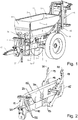
- Fig. 1 is an exemplary embodiment of a pneumatic distribution machine in the form of a uniaxial trailer pulled by a tractor, such as a tractor, which is designed as a pneumatic spreader for powder or particulate distribution material, such as fertilizer and / or seeds.
- a tractor such as a tractor
- a pneumatic spreader for powder or particulate distribution material, such as fertilizer and / or seeds.
- the boom extending transversely to the direction of travel with the delivery lines leading to the individual distributing elements should be referred to the explanations below with reference to FIG Fig. 12 ff referenced.
- the distributing machine has a storage container 1 for receiving the material to be distributed, the side 2, 3, front 4 and rear walls 5 of which taper inwards in the lower area to form a bottom trough which has outlet openings 6, 7, 8 on both sides of the longitudinal axis of the storage container 1, each of which has a metering element (cf. reference numeral 100 in FIG Fig. 4 ), which is assigned below with reference to the Figures 5 to 11 is explained in detail.
- a metering element cf. reference numeral 100 in FIG Fig. 4
- Dosing elements 100 which cannot be identified in detail, are arranged, for example, at different heights and each supply a plurality of conveying lines with the dosed distribution material, the conveying lines being combined into packets and initially led backwards to a lifting frame 9 and then deflected outwards.
- the lifting frame 9 takes the in Fig. 1 boom not shown (see Figures 12 and 13 ), which extend on both sides essentially perpendicular to the direction of travel.
- Each boom is expediently pivoted to the lifting frame 9 and designed to be multi-articulated, so that individual boom sections can be folded together with the conveyor lines from an outwardly extended operating position into a folded rest or travel position.
- the conveying lines taken up by the booms end at different distances from the longitudinal axis of the distribution machine at distribution elements, which are designed, for example, as baffle plates or baffle plates, in order to distribute the flow of distribution material emerging from the conveying lines into surface areas arranged next to one another on the floor (cf. Figures 12 to 16 ).
- the storage container 1 is received by a support frame, which in the present case has a central strut 10, for example in the form of a rectangular tube, on the top of which a structure 11 is fixed, which for example has a tunnel-shaped shape.
- a drawbar 12 for example resilient, is attached, while an axle frame 13 is fixed at the rear end.
- a supporting structure is attached, which consists of cross members 14 as well as this side cheeks 15 connecting at their ends is formed.
- the tunnel-shaped structure 11 shown in the embodiment shown has on its side walls 21, for example, assembly openings 22, 23 and brackets 24 for the arrangement of functional parts, the brackets 24 receiving the metering elements described in more detail below, including their drives.
- the supply lines, such as hydraulic lines and / or electrical lines, can be laid within the tunnel-shaped structure 11.
- the structure 11 On its upper side, the structure 11 is designed in the manner of an upwardly tapering gable 25 which, together with its side walls 21, forms a partition in the storage container 1.
- the gable 25 diverts the material to be distributed located in the storage container 1 to the outlet openings 6, 7, 8 of the storage container 1, which are arranged to the right and left thereof, with the metering elements 100 arranged downstream thereof.
- a step platform 26, for example, which is accessible via a ladder, can also be arranged on the structure 25.
- a parking foot 27 is pivotably attached to the strut 10.
- each blower 28, 29 is routed, for example, through the storage container 1 and has one outlet 31, 32, 33 associated with each metering element 100, which is connected upstream of a respective metering element 100 to a respective one Air distributor 34, 35, 36 opens, for example by means of hose lines not shown in the drawing.
- each conveying line 37 is assigned a transfer chamber 38, 39, 40, which can be equipped in the usual way with an injector (not shown) comprising a nozzle and a diffuser and into which the metered distribution material from is transferred to the respective metering device 100. While the conveying lines 37 acted upon by the fan 28 lead into the boom on the left in the direction of travel, the conveying lines 37 supplied by the fan 29 lead into the boom on the right in the direction of travel (see also FIG Fig. 12 ff).
- the number of delivery lines 37 assigned to each metering element 100 corresponds to the relatively large width of a conventional part-width section control during operation.
- the conveying lines 37 can furthermore be designed as separate sections between the metering elements 100 in order to fold down a section thereof, for example together with a respective transfer chamber 38, 39, 40 (cf. the dashed line illustration in FIG Fig. 4 ) and in this way, for example, carry out calibration tests or empty the storage container 1.
- the Fig. 5 shows a detailed view of the pneumatic distribution machine in the area of one of its metering elements 100, which has a rotatably driven metering roller 101, which in the present case is designed, for example, in the manner of a cam roller, but of course also in the manner of a cellular wheel roller or any other known type, depending on the type of material to be distributed Way can be designed.
- Each metering element 100 supplies a plurality of - here five - conveyor lines 37 and comprises a metering housing 102, which is arranged below a respective outlet opening 6, 7, 8 of the storage container 1 (see above) and the material to be distributed up to the surface of the metering roller 101 able to guide.
- the metering housing 102 can be pivoted downward, for example by means of a lever 52, in order to make the space below the metering roller 101 accessible and to be able to empty the storage container 1.
- the metering roller 101 of each metering element 100 comprises one of the number of conveying lines 37 which are supplied by the metering element 100, corresponding to the number of - here five - dosing wheel segments 103, which are rotatably driven independently of one another.
- this is done by means of an electric motor 104 that is assigned to a respective metering wheel segment 103 and can be controlled and / or regulated independently of one another in order to both shut down individual metering wheel segments 103 of the metering roller 101 and to be able to drive the metering wheel segments 103 at different rotational speeds.
- the electric motors 104 used to drive the metering wheel segments 103 are each designed in the present case by a brushless direct current motor designed as a gear motor, but can in principle of course can also be used as a different type of electric motor or as a hydraulic motor.
- the metering wheel segments 103 of the metering roller 101 are mounted on an essentially tubular hollow body 105 which extends coaxially to its axis of rotation and which is rigidly, but preferably releasably, fixed in the metering housing 102 and, as it is in the Fig. 11 is shown again as such.
- the - here electrical - drives 104 of the metering wheel segments 104 are protected from external influences and received in the interior of the essentially tubular hollow body 105 and, for example, on fastening flanges 106 in the interior of the hollow body 105 (cf. Figures 8 and 10 ) screwed.
- the fastening flanges 106 can, for example, be welded or screwed to the inner circumference of the hollow body 105 (cf. the fastening bores 107 of FIG Fig. 11 ).
- the essentially tubular hollow body 105 has an overall approximately circular cylindrical shape and in the present case comprises a plurality of axially spaced sections 107, which extend around its entire circumference and serve to accommodate bearings 108 applied to the outer circumference, by means of which each metering wheel segment 104 is mounted adjacent to one another at its two axial ends and in the axial direction.
- the full circumferential sections 107 are provided on the one hand at the two ends of the essentially tubular hollow body 105, on the other hand at equidistant intervals in the axial direction thereof, the axial spacing of the full circumferential sections 107 being adapted to the axial length of each metering wheel segment 103.
- the bearings 108 in the present case are designed as sliding bearings in order to achieve a very small installation space and on the one hand an inner bearing shell 108a, which sits on the outer circumference of a respective full-circumferential section 107 of the essentially tubular hollow body 105, and on the other hand have an outer bearing shell 108b on which the axial ends of the metering wheel segments 103 sit.
- the bearings 108 are designed as twin bearings and have two outer bearing shells 108b which can be rotated independently of one another with respect to the inner bearing shell 108a and which each receive the end of one of the adjacent metering wheel segments 103.
- each metering wheel segment 103 can be pushed onto the hollow body 105 in the axial direction from one end of the hollow body 105 equipped with the bearings 108, with a retaining ring 109 serving as an abutment for the metering wheel segments 103 at each end of the essentially tubular hollow body 105 (cf. . the Fig. 6 and 7th ) can be provided, of which at least one can be releasably attached to the outer circumference of the hollow body 105 in order to mount the dosing wheel segments 103 axially fixed, but rotatable independently of one another and interchangeable with one another on the hollow body 105.
- the dosing wheel segments 103 which are mounted close to one another in the axial direction on the essentially tubular hollow body 105, are sealed against one another on their facing end faces with mechanical seals 110 - here in the form of labyrinth seals - in order to prevent the penetration of distribution material as well as dirt and To prevent moisture in the interior of the hollow body 105 receiving the drives 104.
- the essentially tubular hollow body 105 has one or more passage openings 111 between its full circumferential sections 107, which in the assembled state of the metering wheel segments 103 are each overlapped by the metering wheel segments 103.
- the through openings 111 of the hollow body 105 serve to connect a respective drive 104 to a respective metering wheel segment 103, which for this purpose has internal teeth 112 extending around an inner circumferential section (cf. Figures 6 to 8 ), which is left free through a respective through opening 111 of the hollow body 105.
- each drive 104 each formed by an electric geared motor, is also housed encapsulated in a housing in order to protect it as best as possible from mechanical effects as well as from dirt and moisture.
- each metering wheel segment 103 is preferably assigned a position detection sensor (not shown in the drawing), such as a speed sensor or the like, which can be integrated, for example, in a respective motor of the drives 104 or in their gears.
- Both the sensors and the drives 104 are operatively connected to individual or shared control modules of a control and / or regulating device of the distribution machine, also not shown in the drawing, in order to be able to control and / or regulate the speed of the individual metering wheel segments 103 of the metering members 100 independently of one another and thereby a very precise distribution of the material to be distributed to ensure in the field according to application maps, the position of the distribution machine in the field by means of known position detection systems, such as GPS or the like, can be determined in real time.
- the metering roller 101 has a plurality of guide plates 53 (cf. Fig. 5 ), which are arranged in a distance corresponding to the axial length of a respective metering wheel segment 103 of the metering roller 101 and extend from the outer circumference of the metering roller 101 between two adjacent metering wheel segments 103 down to the upper inlet of each transfer chamber 34, 35, 36 .
- the essentially tubular hollow body 105 preferably at least one of its ends penetrates the metering housing 102 to the outside in order to electrically contact the drives 104 housed in its interior from its axial direction by also laying the supply lines inside the hollow body 105 are.
- FIG. 12 A section of a boom provided overall with the reference numeral 60 - here: the boom 60 on the left as viewed in the direction of travel - of the pneumatic distributor is shown schematically, which is attached to its lifting frame 9 (cf. Fig. 1 ) is pivotably attached.
- each boom 60 accommodates a plurality of the conveying lines 37 of the goods to be distributed connected to a respective transfer chamber 38, 39, 40 - usually half of all conveying lines 37 - with the conveying lines 37 at different distances from the longitudinal axis of the distributing machine Distribution elements end, which in the present case are designed as baffle plates 61 or baffle plates in order to distribute the flow of distribution material exiting from a respective conveying line 37 and dosed by a respective dosing wheel segment 103 of the dosing elements 100 into adjacent surface areas on the floor.
- the adjacent baffle plate (s) 61 from which the material to be distributed partially enters the lanes of the trailer and / or the tractor pulling it, can be provided with limiting devices 63 in order to prevent the material to be distributed (also) along the Lanes is distributed and in this way to ensure a saving in distribution goods.
- the setting of a mass flow of material to be distributed, reduced according to the tire width, with which the baffle plates 61 provided with the limiting devices 63 are supplied, is possible in a simple manner due to the finely divided sections corresponding to the number of distribution elements in the form of baffle plates 61 by means of the dosing elements 100 according to the invention that the respective baffle plate 61 via the associated delivery line 37 associated Dosierradsegmenten 103 is driven with a compared to the other Dosierradsegmenten 103 lower rotational speed.
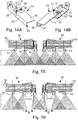
- FIGS 14A and 14B are schematic views of an embodiment of such a delimitation device 63, which is releasably attached to a baffle plate 61 or formed jointly with the baffle plate 61, which are used by known border spreading devices in the form of baffles, as they are sometimes used in pneumatic distributing machines for the outer limitation of the working width, differ on the one hand in that the limiting device 63 has an essentially U-shaped profile, the U-web 64 of which extends approximately perpendicular to the plane of the impact plate 61 when it is mounted on the impact plate 61.
- a long U-leg 64 adjoins the U-web 64 of the limiting device 63 at an approximately right angle on the one hand on the upper side and on the other hand a short U-leg 65 on the lower side, the U-legs 64, 65 in the assembled state are arranged in planes approximately parallel to the plane of the baffle plate 61. In this way, it is reliably prevented that the particles to be distributed which bounce off the limiting device 63 are reflected into the partial widths of adjacent distributing members.
- the limiting devices 63 differ from conventional border spreading devices that can be mounted on the outer baffle plate to limit the working width, in particular in that they are adjustably mounted on the baffle plate 61 or - if the limiting device 63 is designed together with the baffle plate 61 - in relation to the baffle plate 61 can be adjusted to different distribution parameters, such as in particular the width and the position of the tires predetermined lanes, but also, for example, the mounting height of the boom 60 or the distance of the distribution elements 61 from the ground, the type of distribution material including its flight characteristics, the lateral distance of the distribution elements 61 from one another, etc., to be able to take into account.
- the adjustability of the limiting devices 63 is given in the present exemplary embodiment in that they can be pivoted about an axis A extending approximately perpendicular to the two U-legs 64, 65 or perpendicular to the plane of the baffle plate 61 with respect to the baffle plate 61, which is for example by means of a corresponding bores on the one hand in the baffle plate 61 and on the other hand in the screw 66 penetrating through the limiting device 63 or the like.
- a scale 67 can be used to display the adjustment angle set in each case, which in the embodiment shown is arranged on a support section 68 of the long U-leg 64 of the limiting device 63, which is firmly connected to the impact plate 61, and in sections through a through opening of the support section 68 overlapping and around it the axis A pivotally articulated terminal section of the long U-leg 64 is visible.
- the limiting device 63 can be provided that it can be set not only manually, but also by means of a motor and, in particular, remotely, for example by means of a controlled motor, actuator or the like (not shown in the drawing).
- the control and / or regulating device of the distribution machine can be designed to input a desired setting angle of the limiting device 63 and / or to input the aforementioned parameters, the control and / or regulating device in the latter case using the suitable setting angle the limiting device 63 is able to calculate as a function of the parameters entered.
- FIG. 15 While in the Fig. 15 the situation of normal spreading is shown, in which all distribution elements 61 are supplied with the desired mass flow of distribution material by means of a respective metering wheel segment 103 of the metering rollers 101 of the metering elements 100 and the scattering cones reflected by the baffle plates 61 overlap each other in order to ensure uniform transverse distribution worry is in the Fig. 16 the situation is shown as it arises when the tramlines of the pneumatic distribution machine are spared at least by the width B of their wheels or tires in the manner described above, by having the baffle plates 61 adjacent to a respective tramline on the one hand with a correspondingly adjusted limiting device 63 (cf.
Description
Die Erfindung betrifft ein Dosierorgan mit einer in einem Dosiergehäuse gelagerten, rotierbar angetriebenen Dosierwalze, welches zum Einsatz in einer landwirtschaftlichen Maschine zum Ausbringen von Verteilgut geeignet ist, wobei die Dosierwalze eine Mehrzahl an auf einem sich koaxial zu deren Drehachse erstreckenden Hohlkörper gelagerten Dosierradsegmenten aufweist und einem jeweiligen Dosierradsegment der Dosierwalze ein eigener Antrieb zugeordnet ist, um die Dosierradsegmente unabhängig voneinander anzutreiben. Die Erfindung bezieht sich ferner auf eine landwirtschaftliche Maschine zum Ausbringen von Verteilgut, insbesondere Dünger und/oder Saatgut, mit wenigstens einem Dosierorgan der vorgenannten Art.The invention relates to a metering member with a rotatably driven metering roller mounted in a metering housing, which is suitable for use in an agricultural machine for spreading material to be spread, the metering roller having a plurality of metering wheel segments mounted on a hollow body extending coaxially to its axis of rotation and a each metering wheel segment of the metering roller is assigned its own drive in order to drive the metering wheel segments independently of one another. The invention also relates to an agricultural machine for spreading material to be distributed, in particular fertilizer and / or seeds, with at least one metering element of the aforementioned type.
Landwirtschaftliche Maschinen, deren Dosierorgane drehangetriebene Dosierwalzen umfassen, sind insbesondere in Form von Düngerstreuern und/oder Sämaschinen zum Ausbringen von pulver- bzw. partikelförmigem Verteilgut, wie Dünger, Saatgut und dergleichen, in vielfältiger Ausgestaltung bekannt und umfassen üblicherweise einen Vorratsbehälter zur Aufnahme des Verteilgutes, unterhalb dessen das oder die Dosierorgan(e) angeordnet ist bzw. sind. Während als Dosierorgane häufig auch mit einer Auslauföffnung des Vorratsbehälters zusammenwirkende, aktuatorisch oder manuell betätigte Dosierschieber zum Einsatz gelangen, weist das Dosierorgan bei den hier in Frage stehenden landwirtschaftlichen Maschinen einer rotierbar angetriebene Dosierwalze auf, welche insbesondere in Form einer Zellenrad- und/oder Nockenradwalze ausgestaltet sein kann. Die Dosierwalze ist in einem Dosiergehäuse gelagert, welches üblicherweise einen an seiner Oberseite angeordneten, beispielsweise mit dem Vorratsbehälter in Verbindung stehenden Einlass und eine an seiner Unterseite angeordneten Auslass aufweist. Ein solches Dosierorgan ist beispielsweise aus der
Landwirtschaftliche Maschinen, welche von Dosierwalzen umfassenden Dosierorganen Gebrauch machen, können im einfachsten Fall beispielsweise von sogenannten Kastenstreuern bzw. Kastensämaschinen gebildet sein, bei welchen das in einem Vorratsbehälter auf Vorrat gehaltene und mittels der Dosierwalze des Dosierorgans dosierte Verteilgut rein aufgrund Schwerkraft entweder über eine oder mehrere, z.B. am Ende von sich bis oberhalb des Bodens erstreckenden Schläuchen vorgesehenen, Ablageöffnungen auf die Oberfläche des Bodens ausgebracht oder, z.B. mittels geeigneter Injektionseinrichtungen, Säzinken, Säscharen und dergleichen, in den Boden eingebracht wird. Solche Kastenstreuer bzw. Kastensämaschinen, welche in der Regel als Nachläufer oder als Anbaugeräte für Zugmaschinen, wie Traktoren, konzipiert sind, dienen vornehmlich zum Ausbringen des Verteilgutes entlang relativ schmaler Flächen, wie beispielsweise im Gemüseanbau zum Verteilen von Dünger auf verhältnismäßig schmale Beetflächen. Ihre Arbeitsbreite, welche weitestgehend der Streubreite entspricht, beträgt oft in der Größenordnung von beispielsweise etwa 80 cm bis etwa 3 m. Sofern das Verteilgut nur auf eine Teilbreite ausgebracht werden soll, wie es z.B. beim Ausbringen des Verteilgutes an einem Feld- oder Beetrand erforderlich sein kann, können die nicht benötigten Axialabschnitte der Dosierwalze, welche je nach dem auszubringenden Verteilgut z.B. als Zellenrad- oder Nockenwalze ausgestaltet und vorteilhafterweise entweder gänzlich austauschbar oder aus einzelnen, gegeneinander austauschbaren Zellenrad- oder Nockenradsegmenten zusammengesetzt sein kann (vgl. z.B. die oben zitierte 2 786 649 B1), mit die Zellenradkammern bzw. die Nockentäler überdeckenden Blindringen versehen werden, was sich jedoch in handhabungstechnischer Hinsicht als aufwändig und mühsam erweisen kann.Agricultural machines that make use of metering devices comprising metering rollers can, in the simplest case, be, for example, so-called box spreaders or box seeders, in which the material to be distributed in a storage container and metered by means of the metering roller of the metering device is purely due to gravity either through one or more , for example provided at the end of hoses extending up to above the soil, deposit openings are made on the surface of the soil or, for example, introduced into the soil by means of suitable injection devices, seed prongs, seed coulters and the like. Such box spreaders or box seeders, which are usually designed as backers or as attachments for tractors such as tractors, are primarily used to spread the spreading material along relatively narrow areas, such as in vegetable growing for spreading fertilizer on relatively narrow bed areas. Their working width, which largely corresponds to the spreading width, is often in the order of magnitude of, for example, about 80 cm to about 3 m the material to be distributed is only to be spread over a partial width, as may be necessary, for example, when spreading the material to be spread at the edge of a field or bed, the unneeded axial sections of the metering roller, which, depending on the material to be spread, are designed, for example, as a cellular wheel or cam roller, and advantageously can either be completely interchangeable or composed of individual, mutually interchangeable cell wheel or cam wheel segments (cf., for example, the above-cited 2 786 649 B1), can be provided with blind rings covering the cell wheel chambers or the cam valleys, which, however, turns out to be laborious and complex from a handling point of view arduous can prove.
Ferner finden Dosierorgane mit einer in einem Dosiergehäuse gelagerten, rotierbar angetriebenen Dosierwalze insbesondere in pneumatischen Verteilmaschinen Verwendung, welche gleichfalls als pneumatische Düngerstreuer und/oder pneumatische Sämaschinen ausgestaltet sein können. Pneumatische Verteilmaschinen können gleichfalls einerseits in leichter Bauart als Anbaugeräte verwirklicht sein, welche mit dem Dreipunkt einer Zugmaschine, wie eines Traktors, gekoppelt werden können, anderseits können sie in schwerer Bauart auf einen achsgestützten Nachläufer oder einen Selbstfahrer aufgesetzt sein. Sie umfassen üblicherweise eine Mehrzahl an seitlich nach außen ragenden Auslegern, welche in unterschiedlichem Abstand voneinander endende Förderleitungen aufnehmen. Zur Förderung des Verteilgutes dient ein Gebläse, dessen Druckleitung sich an einen Auslass des Dosiergehäuses eines jeweiligen Dosierorgans anschließt und in einem Druckverteiler mündet, an welchen sich die Förderleitungen anschließen. Zwischen dem Druckverteiler und den Förderleitungen angeordnete Übergabekammern, welche zweckmäßigerweise mit jeweils eine Düse und einen Diffusor umfassenden Injektoren ausgestattet sein können, dienen zur Übergabe des Streugutes von der Dosierwalze des Dosierorgans an die Förderleitungen, um sicherzustellen, dass jeder Förderleitung dieselbe Menge an Verteilgut aufgegeben wird. Das Verteilgut wird schließlich pneumatisch über die nach außen umgelenkten Förderleitungen bis zu deren Ende gefördert, wo das Streugut an entsprechende Verteilorgane überführt wird.In addition, metering devices with a metering roller that is rotatably driven and mounted in a metering housing are used, in particular, in pneumatic distributing machines, which can also be designed as pneumatic fertilizer spreaders and / or pneumatic seeders. Pneumatic distribution machines can also be implemented in a lightweight design as attachments, which can be coupled to the three-point of a tractor, such as a tractor, on the other hand, they can be mounted in a heavy design on an axle-supported trailer or a self-propelled device. They usually include a plurality of laterally outwardly protruding arms, which receive conveyor lines ending at different distances from one another. A fan is used to convey the material to be distributed, the pressure line of which is connected to an outlet of the dosing housing of a respective dosing element and opens into a pressure distributor to which the conveying lines are connected. Transfer chambers which are arranged between the pressure distributor and the delivery lines and which expediently each have a nozzle and Injectors comprising a diffuser can be used to transfer the material to be spread from the metering roller of the metering element to the delivery lines, in order to ensure that the same amount of material to be distributed is applied to each delivery line. The material to be spread is finally conveyed pneumatically via the outwardly deflected conveying lines to the end of the line, where the material to be spread is transferred to the corresponding distribution elements.
Je nach Ausgestaltung der landwirtschaftlichen Maschine zum Ausbringen von Verteilgut bzw. je nach Art des auszubringenden Verteilgutes können die Verteilorgane im einfachsten Fall z.B. Ablageöffnungen aufweisen, aus welchen das Verteilgut infolge Schwerkraft mehr oder minder linienförmig auf der Oberfläche des Bodens ausgebracht wird, wie es beispielsweise für die Reihendüngung erwünscht sein kann. Die Ablageöffnungen können dabei z.B. unmittelbar unterhalb des Dosierorgans oder auch am Ende von Schlauchleitungen vorgesehen sein, welche sich stromab des Dosierorgans bis unmittelbar oberhalb des Bodens erstrecken, damit das Verteilgut keinen Windeinflüssen unterliegt, wenn es zu Boden fällt. Ferner können insbesondere im Falle von pneumatischen Verteilmaschinen der oben genannten Art als Verteilorgane Prallteller bzw. Prallplatten vorgesehen sein, auf welche das in einer jeweiligen Förderleitung pneumatisch transportierte Verteilgut auftrifft und von dort im Wesentlichen fächerförmig auf dem Boden abgelegt wird. Andersartige Verteilorgane, wie sie insbesondere zur Verteilung von Saatgut, aber auch für die Tiefendüngung zum Einsatz gelangen, umfassen Injektionseinrichtungen zum Einbringen des Verteilgutes in den Boden, wie sie beispielsweise aus der
Eine derartige pneumatische Verteilmaschine ist in Form eines pneumatischen Düngerstreuers beispielsweise aus der
Indes lässt sich auf diese Weise eine nur relativ grobe Teilbreitenschaltung realisieren, da die unabhängig voneinander drehangetrieben Dosierorgane jeweils mit Gruppen von Verteilorganen kommunizieren, aber die Zuordnung eines eigenen Dosierorgans einem jeweiligen Verteilorgan aus Platzgründen praktisch nicht möglich, geschweige denn wirtschaftlich wäre. Um innerhalb einer Teilbreite einzelne Verteilorgane abschalten zu können, wie es beispielsweise beim Ausbringen von Verteilgut im Bereich des Feldrandes in Bezug auf die äußeren Verteilorgane erforderlich sein kann, bleibt folglich auch bei pneumatischen Verteilmaschinen in der Regel nichts anderes übrig, als die mit den nicht benötigten Verteilorganen über eine jeweilige Übergabekammer in Verbindung stehenden Axialabschnitte der Dosierwalze, welche je nach dem auszubringenden Verteilgut wiederum z.B. als Zellenrad- oder Nockenwalze ausgestaltet und vorteilhafterweise entweder gänzlich austauschbar oder aus einzelnen, gegeneinander austauschbaren Zellenrad- oder Nockenradsegmenten zusammengesetzt sein kann (vgl. z.B. die oben zitierte 2 786 649 B1), mit die Zellenradkammern bzw. die Nockentäler überdeckenden Blindringen zu versehen.In this way, however, only a relatively coarse part-width section switching can be implemented, since the dosing elements, driven independently of one another, communicate with groups of distributing elements, but the allocation of a separate dosing element to a respective distributing element is practically impossible, let alone economical, for reasons of space. In order to be able to switch off individual distribution elements within a partial width, as may be necessary, for example, when spreading material to be distributed in the area of the field edge in relation to the outer distribution elements, there is usually nothing else to do with pneumatic distribution machines than those with the ones that are not required Axial sections of the metering roller which are connected via a respective transfer chamber and which, depending on the material to be distributed, in turn are designed, for example, as a cellular wheel or cam roller and can advantageously either be completely interchangeable or composed of individual, mutually interchangeable cellular wheel or cam wheel segments (see, for example, the above cited 2 786 649 B1), to be provided with blind rings covering the cellular wheel chambers or the cam valleys.
Die
Der
Die
Der Erfindung liegt die Aufgabe zugrunde, eine landwirtschaftliche Maschine zum Ausbringen von Verteilgut der eingangs genannten Art sowie ein für eine solche landwirtschaftliche Maschine geeignetes Dosierorgan mit einer in einem Dosiergehäuse gelagerten, rotierbar angetriebenen Dosierwalze unter zumindest weitestgehender Vermeidung der vorgenannten Nachteile dahingehend weiterzubilden, dass eine gegenüber dem Stand der Technik genauere Dosierung sowie insbesondere eine individuelle Dosierung des Verteilgutes innerhalb kleiner Teilbreiten der landwirtschaftlichen Maschine bei einem kompakten Aufbau des Dosierorgans ermöglicht wird.The invention is based on the object of developing an agricultural machine for discharging distribution material of the type mentioned at the outset, as well as a metering element suitable for such an agricultural machine with a rotatably driven metering roller mounted in a metering housing, while at least largely avoiding the aforementioned disadvantages, to the effect that one opposite the prior art enables more precise metering and, in particular, individual metering of the distribution material within small sections of the agricultural machine with a compact design of the metering element.
Erfindungsgemäß wird diese Aufgabe bei einem Dosierorgan sowie bei einer mit wenigstens einem solchen Dosierorgan versehenen landwirtschaftlichen Maschine der eingangs genannten Art dadurch gelöst, dass die Antriebe der Dosierradsegmente der Dosierwalze im Innern der Dosierradsegmente angeordnet sind, wobei die Antriebe der Dosierradsegmente der Dosierwalze im Innern des die Dosierradsegmente lagernden Hohlkörpers festgelegt sind und jeweils ein einem jeweiligen Dosierradsegment zugeordnetes Zahnrad aufweisen, die Mantelfläche des Hohlkörpers zumindest an ihrem einem jeweiligen Zahnrad zugeordneten Axialabschnitt eine Durchgangsöffnung aufweist und ein jeweiliges Zahnrad mit einer jeweiligen Innenverzahnung eines jeweiligen Dosierradsegmentes im Eingriff steht.According to the invention, this object is achieved with a metering element and with one with at least one such metering element provided agricultural machine of the type mentioned at the outset in that the drives of the metering wheel segments of the metering roller are arranged inside the metering wheel segments, the drives of the metering wheel segments of the metering roller being fixed inside the hollow body supporting the metering wheel segments and each having a gear assigned to a respective metering wheel segment, the lateral surface of the hollow body has a through opening at least on its axial section assigned to a respective gear wheel and a respective gear wheel is in engagement with a respective internal toothing of a respective metering wheel segment.
Die erfindungsgemäße Ausgestaltung der Dosierwalze des Dosierorgans ermöglicht bei einem äußerst kompakten Aufbau eine individuelle Dosierung des Verteilgutes entlang der einzelnen, von einem jeweiligen Dosierradsegment gebildeten Axialabschnitte der Dosierwalze, indem die Dosierradsegmente mittels ihres jeweiligen Antriebs unabhängig voneinander rotierbar angetrieben sind. Einzelne Dosierradsegmente können folglich abgeschaltet werden, so dass dort keine Dosierung stattfindet, während andere Dosierradsegmente mit der dem gewünschten Massenstrom an Verteilgut entsprechenden Drehzahl drehangetrieben werden können, um das Verteilgut nur dort auszubringen, wo es gewünscht ist.The inventive design of the metering roller of the metering element enables individual metering of the material to be distributed along the individual axial sections of the metering roller formed by a respective metering wheel segment, with the metering wheel segments being driven independently of one another by means of their respective drive. Individual metering wheel segments can consequently be switched off so that no metering takes place there, while other metering wheel segments can be driven in rotation at the speed corresponding to the desired mass flow of distribution material in order to only apply the distribution material where it is desired.
Darüber hinaus ist es aufgrund der den Dosierradsegmenten der Dosierwalze zugeordneten individuellen Antrieben möglich, dass die einzelnen Dosierradsemente nicht nur entweder mit der gewünschten Drehzahl angetrieben oder stillsetzbar sind, sondern insbesondere auch mit praktisch beliebigen unterschiedlichen Drehzahlen angetrieben werden können, um jede mit einem jeweiligen Dosierradsegment der Dosierwalze korrespondiere Teilbreite mit dem individuell gewünschten Massenstrom an Verteilgut zu versorgen. Auf diese Weise lassen sich innerhalb fein unterteilter Teilbreiten über die Arbeitsbreite der landwirtschaftlichen Maschine jeweils die erforderliche Verteilmengen exakt dosieren, so dass insbesondere eine Verteilung des Verteilgutes in Abhängigkeit von der jeweiligen Position der landwirtschaftlichen Maschine auf dem Feld gemäß vorgegebener Applikationskarten mit sehr hoher Genauigkeit möglich wird. Die Positionserfassung der landwirtschaftlichen Maschine kann dabei mittels bekannter, in der Regel satellitengestützter Positionserfassungssysteme, wie GPS oder dergleichen, geschehen, wie sie bei modernen landwirtschaftlichen Verteilmaschinen inzwischen zum Stand der Technik gehören. Zudem ist es selbstverständlich möglich, durch Verlangsamen bzw. Beschleunigen einzelner Dosierradsegmente der Dosierwalze bei der Kurvenfahrt der landwirtschaftlichen Maschine derart, dass einem jeweiligen Dosierradsegment zugeordnete und unter verschiedenen seitlichen Abständen in Bezug auf die Fahrtrichtung der landwirtschaftlichen Maschine angeordnete Verteilorgane im Kurveninnern mit von innen nach außen abnehmenden Massenströmen an Verteilgut und im Kurvenäußeren mit von innen von außen zunehmenden Massenströmen an Verteilgut versorgt werden, die bei der Kurvenfahrt andernfalls verursachten kurveninnenseitigen Überversorgungen bzw. die kurvenaußenseitigen Unterversorgungen des Bodens mit dem Verteilgut zu kompensieren, wie es als solches aus der eingangs erwähnten
Es ergibt sich folglich eine sehr feine Unterteilung an möglichen Teilbreiten, wobei ein jedes Dosierradsegment eine Teilbreite der gesamten Arbeitsbreite der landwirtschaftlichen Maschine zu versorgen vermag. Das erfindungsgemäße Dosierorgan bietet sich dabei insbesondere für alle bekannten landwirtschaftlichen Maschinen an, welche zum Ausbringen von pulver- oder partikelförmigen Verteilgütern, wie insbesondere Dünger und/oder Saatgut, dienen, seien sie beispielsweise von relativ einfach aufgebauten, sogenannten Kastenstreuern oder Kastensämaschinen gebildet, bei welchen das Verteilgut stromab der einzelnen Dosierradsegmente der Dosierwalze auf den Boden fällt, oder seien sie beispielsweise von demgegenüber komplexeren pneumatischen Verteilmaschinen gebildet, bei welchen das Verteilgut stromab der einzelnen Dosierradsegmente der Dosierwalze an verschiedenartige Verteilorgane überführt werden kann, welche in unterschiedlichen Seitenabständen in Bezug auf die Fahrtrichtung angeordnet sind.This results in a very fine subdivision of possible partial widths, with each metering wheel segment being able to supply a partial width of the entire working width of the agricultural machine. The metering device according to the invention is particularly suitable for all known agricultural machines which are used to apply powder or particulate distribution goods, such as fertilizers and / or seeds, for example, whether they are made up of relatively simply constructed so-called box spreaders or box seeders, in which the material to be distributed falls to the floor downstream of the individual metering wheel segments of the metering roller, or be formed, for example, by more complex pneumatic distributing machines, in which the material to be distributed downstream of the individual metering wheel segments of the metering roller can be transferred to various types of distributing elements, which are at different lateral distances in relation to the direction of travel are arranged.
Die Antriebe der Dosierradsegmente der Dosierwalze sind dabei erfindungsgemäß im Innern der Dosierradsegmente angeordnet. Auf diese Weise ergibt sich einerseits ein äußerst kompakter Gesamtaufbau des Dosierorgans, indem das zur Verfügung stehende Innenvolumen der Dosierwalze optimal ausgenutzt wird, andererseits ist der oder sind die Antriebe in idealer Weise vor äußeren Einwirkungen geschützt innerhalb der Mantelflächen der Dosierradsegmente der Dosierwalze untergebracht, welche folglich eine Art "Schutzgehäuse" bilden.The drives of the metering wheel segments of the metering roller are arranged according to the invention in the interior of the metering wheel segments. On the one hand, this results in an extremely compact overall design of the metering device, in that the available internal volume of the metering roller is optimally used; on the other hand, the drive (s) is or are ideally protected from external influences within the outer surfaces of the metering wheel segments of the metering roller, which consequently form a kind of "protective housing".
Die Dosierradsegmente der Dosierwalze können im Übrigen je nach auszubringendem Verteilgut, wie verschiedenen Saatgütern einschließlich Feinsaat und/oder verschiedenen Düngemitteln, zweckmäßigerweise von Nockenradsegmenten und/oder Zellenradsegmenten gebildet sein, wobei selbstverständlich auch Dosierradsegmente mit beliebigen bekannten andersartigen Dosierstrukturen zum Einsatz gelangen können, wie beispielsweise solche nach Art von Zellenradsegment-, Loch-, Nutenwalzen oder dergleichen. Ferner können selbstverständlich verschiedenartige Dosierradsegmente miteinander kombiniert werden, um mit ein und derselben Dosierwalze unterschiedliche Verteilgutmengen und/oder -sorten ausbringen zu können.The metering wheel segments of the metering roller can also, depending on the material to be spread, such as various seeds including fine seeds and / or various fertilizers, expediently be formed by cam wheel segments and / or cell wheel segments, whereby metering wheel segments with any known different metering structures can of course also be used, such as such in the manner of cellular wheel segment, perforated, grooved rollers or the like. Furthermore, different types of metering wheel segments can of course be combined with one another in order to be able to apply different amounts and / or types of material to be distributed with one and the same metering roller.
In konstruktiver Hinsicht sind die Dosierradsegmente der Dosierwalze erfindungsgemäß auf dem sich koaxial zu deren Drehachse erstreckenden Hohlkörper gelagert, welcher zweckmäßigerweise stationär in dem Dosiergehäuse angeordnet sein kann. Als Lager für die Dosierradsegmente kommen sowohl Wälz- oder Gleitlager in Betracht, wobei sich letztere im Hinblick auf einen sehr geringen Bauraum als vorteilhaft erweisen können. Der als Lagerkörper für die Dosierradsegmente der Dosierwalze dienende Hohlkörper ist zweckmäßigerweise im Wesentlichen rohrförmig ausgestaltet und weist eine kreiszylindrische Mantelfläche auf, welche sich um zumindest einen Teil seines Außenumfangs erstreckt. Der Hohlkörper kann dabei einen im Wesentlichen C- bzw. U-förmigen Querschnitt und/oder einen Kreisquerschnitt besitzen, wobei es hinsichtlich einer hohen Formstabilität von Vorteil sein kann, wenn er zumindest an seinen Axialabschnitten, an welchen die Dosierradsegmente gelagert sind, einen vollumfänglichen Kreisquerschnitt aufweist. Die Antriebe der Dosierradsegmente sind dabei im Innern des die Dosierradsegmente lagernden Hohlkörpers festgelegt, wie beispielsweise an innenseitig des Hohlkörpers vorgesehenen Tragflanschen, an welchen die Antriebe zweckmäßigerweise lösbar befestigbar sind. Zur Übertragung der mittels der Antriebe induzierten Drehbewegung auf die einzelnen Dosierradsegmente weisen die Antriebe jeweils ein einem jeweiligen Dosierradsegment zugeordnetes Zahnrad auf, während der Hohlkörper zumindest an seinem einem jeweiligen Zahnrad zugeordneten Axialabschnitt eine Durchgangsöffnung aufweist, wobei ein jeweiliges Zahnrad mit einer jeweiligen Innenverzahnung eines jeweiligen Dosierradsegmentes im Eingriff steht. Um einem jeden Dosierradsegment einen eigenen Antrieb zuzuordnen und auf diese Weise einen Drehantrieb aller Dosierradsegmente mit verschiedenen Drehgeschwindigkeiten unabhängig voneinander zu gewährleisten, kann z.B. ein abtriebsseitiges Zahnrad eines jeden Antriebs permanent mit der Innenverzahnung eines jeweiligen Dosierradsegmentes im Eingriff stehen, wobei die das Zahnrad tragende Welle zweckmäßigerweise exzentrisch in Bezug auf die Mittelachse des insbesondere etwa kreiszylindrischen Hohlkörpers angeordnet sein kann, dessen Mantelfläche ihrerseits im Bereich des Zahnrades eine Durchgangsöffnung aufweist bzw. sich dort nur um einen Teil des Gesamtumfangs erstreckt, welcher folglich zumindest bereichsweise etwa C- oder U-förmig ausgestaltet sein kann.In structural terms, the metering wheel segments of the metering roller are, according to the invention, mounted on the hollow body which extends coaxially to its axis of rotation and which can expediently be arranged in a stationary manner in the metering housing. Rolling or sliding bearings can be used as bearings for the metering wheel segments, the latter being able to prove to be advantageous with regard to a very small installation space. The hollow body serving as a bearing body for the metering wheel segments of the metering roller is expediently designed essentially tubular and has a circular cylindrical jacket surface which extends around at least part of its outer circumference. The hollow body can have an essentially C-shaped or U-shaped cross-section and / or a circular cross-section, it being advantageous in terms of high dimensional stability if it has a full circular cross-section at least at its axial sections on which the metering wheel segments are mounted having. The drives of the dosing wheel segments are fixed in the interior of the hollow body supporting the dosing wheel segments, such as, for example, on supporting flanges provided on the inside of the hollow body, to which the drives can expediently be releasably attached. To transmit the rotary movement induced by the drives to the individual dosing wheel segments, the drives each have a gear assigned to a respective dosing wheel segment, while the hollow body has a through opening at least on its axial section assigned to a respective gear, each gear having a respective internal toothing of a respective dosing wheel segment is engaged. In order to assign a separate drive to each Dosierradsegmente and in this way to ensure a rotary drive of all Dosierradsegmente with different rotational speeds independently of each other, for example, a gear on the output side of each drive can be permanently engaged with the internal teeth of a respective Dosierradsegmentes, whereby the shaft carrying the gear is expedient can be arranged eccentrically with respect to the central axis of the in particular approximately circular cylindrical hollow body, the lateral surface of which in turn has a through opening in the area of the gear wheel or extends there only around part of the total circumference, which consequently at least in some areas can be approximately C- or U-shaped can.
Die Antriebe der Dosierradsegmente der Dosierwalze können vorzugsweise Elektromotoren oder Hydraulikmotoren umfassen, wobei der motorische Antrieb der Dosierradsegmente in beiden Fällen insbesondere Getriebemotoren aufweisen kann. Im Falle von Elektromotoren bieten sich z.B. vorteilhafterweise Servomotoren an.The drives of the metering wheel segments of the metering roller can preferably comprise electric motors or hydraulic motors, the motorized drive of the metering wheel segments in both cases being able to have, in particular, gear motors. In the case of electric motors, for example, servomotors are advantageous.
Die erfindungsgemäße Ausgestaltung der unabhängig voneinander drehangetriebenen Dosierradsegmente der Dosierwalze mittels im Innern derselben angeordneter Antriebe bietet dabei insbesondere die Möglichkeit, dass die Dosierwalze des Dosierorgans nicht nur zwei, sondern wenigstens drei, vorzugsweise mehr als drei, unabhängig voneinander angetriebene Dosierradsegmente aufweist, welche vorzugsweise sämtlich mittels jeweils eines eigenen Antriebs unabhängig voneinander drehangetrieben sind.The configuration according to the invention of the metering wheel segments of the metering roller, which are driven in rotation independently of one another by means of drives arranged inside the same offers the possibility in particular that the metering roller of the metering member has not only two, but at least three, preferably more than three, independently driven metering wheel segments, which are preferably all driven in rotation independently of one another by means of their own drive.
Die Dosierradsegmente der Dosierwalze können an ihren einander zugewandten Stirnseiten vorzugsweise mittels Gleitringdichtungen, insbesondere in Form von Labyrinthdichtungen, gegeneinander abgedichtet sein, um ein Eindringen von Verteilgut in die Zwischenräume zwischen den Dosierradsegmenten zu verhindern sowie insbesondere auch im Innern des Hohlkörpers aufgenommene Funktionsteile, wie insbesondere den oder die Antriebe der Dosierradsegmente oder Teile derselben, vor eindringendem Schmutz und Feuchtigkeit zu bewahren.The metering wheel segments of the metering roller can be sealed against each other at their facing end faces, preferably by means of mechanical seals, in particular in the form of labyrinth seals, in order to prevent the penetration of distribution material into the spaces between the metering wheel segments and in particular also functional parts received in the interior of the hollow body, such as in particular the or to protect the drives of the dosing wheel segments or parts thereof from penetrating dirt and moisture.
Um die Dosierradsegmente der Dosierwalze an verschiedenartige Verteilgüter anpassen zu können, können die Dosierradsegmente vorteilhafterweise austauschbar auf dem Hohlkörper gelagert sein, wobei die Dosierradsegmente insbesondere
- in Axialrichtung auf den Hohlkörper aufschiebbar sind; und/oder
- mehrteilig in Form von lösbar aneinander befestigbaren, im Wesentlichen kreisbogenförmigen Dosierradsegmentabschnitten ausgebildet sind.
- can be pushed onto the hollow body in the axial direction; and or
- are constructed in several parts in the form of essentially circular arc-shaped dosing wheel segment segments which can be detachably attached to one another.
Die Antriebe der Dosierradsegmente der Dosierwalze können zusätzlich zu ihrer Anordnung im Innern der Dosierradsegmente, wie insbesondere im Innern des diese lagernden Hohlkörpers, in einem Gehäuse untergebracht sein, um für eine Verkapselung zumindest des Antriebsmotors zu sorgen. Darüber hinaus kann zum Schutz der Antriebe vorgesehen sein, dass die Antriebe mit einer inerten Flüssigkeit, insbesondere Öl, wie beispielsweise Transformatoröl oder dergleichen, geflutet ist bzw. sind.The drives of the metering wheel segments of the metering roller can be accommodated in a housing in addition to their arrangement inside the metering wheel segments, such as in particular inside the hollow body supporting them, in order to ensure that at least the drive motor is encapsulated. In addition, to protect the drives, provision can be made for the drives to be or are flooded with an inert liquid, in particular oil, such as transformer oil or the like.
Im Hinblick auf eine genaue Ansteuerung der einzelnen Dosierradsegmente der Dosierwalze kann einem jeden Dosierradsegment vorzugsweise ein Positionserfassungssensor, insbesondere in Form eines Drehzahlsensors, zugeordnet sein, welcher zweckmäßigerweise mit einer Steuer- und/oder Regeleinrichtung der landwirtschaftlichen Maschine in Verbindung steht, welche die einzelnen Dosierradsegmente der Dosierwalze(n) gemäß dem jeweils erforderlichen Massenstrom an Verteilgut steuert und/oder regelt. Ein solcher Drehzahlsensor kann z.B. an einem jeweiligen Dosierradsegment bzw. an dem diese lagernden Hohlkörper, an einem mit den Dosierradsegmenten der Dosierwalze im Eingriff stehenden Zahnrad bzw. an einer dieses tragenden Welle oder einer Welle des Antriebsmotors oder dessen Getriebe vorgesehen sein.With a view to precise control of the individual metering wheel segments of the metering roller, each metering wheel segment can preferably be assigned a position detection sensor, in particular in the form of a speed sensor, which is expediently connected to a control and / or regulating device of the agricultural machine that controls the individual metering wheel segments Dosing roller (s) controls and / or regulates according to the required mass flow of material to be distributed. Such a speed sensor can be provided, for example, on a respective metering wheel segment or on the hollow body supporting it, on a gear wheel in engagement with the metering wheel segments of the metering roller or on a shaft supporting this or a shaft of the drive motor or its gear.
Darüber hinaus kann zu steuerungs- bzw. regeltechnischen Zwecken vorgesehen sein, dass
- einem jeweiligen Antrieb eines jeweiligen Dosierradsegmentes und/oder
- Gruppen von Antrieben mehrerer Dosierradsegmente
- a respective drive of a respective dosing wheel segment and / or
- Groups of drives for several metering wheel segments
In konstruktiver Hinsicht kann mit Vorteil ferner vorgesehen sein, dass den Dosierradsegmenten der Dosierwalze eine Mehrzahl an Leitblechen zugeordnet ist, welche in einem der axialen Länge eines jeweiligen Dosierradsegmentes entsprechenden Abstand voneinander angeordnet sind und sich zwischen jeweils zwei benachbarten Dosierradsegmenten bis unmittelbar an die Mantelfläche der Dosierwalze erstrecken. Die insbesondere an dem auslassseitigen Mantelflächenabschnitt der Dosierradsegmente angeordneten Leitbleche dienen zur Verhinderung einer Vermischung der von jeweils benachbarten Dosierradsegmenten dosierten, gegebenenfalls unterschiedlichen Massenströme an Verteilgut, so dass es insbesondere in einfacher Weise möglich ist, den von einem jeden Dosierradsegment dosierten Massenstrom an Verteilgut mit hoher Genauigkeit, z.B. pneumatisch, einem separaten Verteilorgan zuzuführen.From a structural point of view, it can also advantageously be provided that the metering wheel segments of the metering roller are assigned a plurality of guide plates, which are arranged at a distance from one another corresponding to the axial length of a respective metering wheel segment and extend between each two adjacent metering wheel segments right up to the outer surface of the metering roller extend. The guide plates arranged in particular on the outer surface section of the metering wheel segments on the outlet side are used to prevent mixing of the possibly different mass flows of distribution material metered by adjacent metering wheel segments, so that it is particularly easy to feed the mass flow of distribution material metered by each metering wheel segment with high accuracy, e.g. pneumatically, to a separate distributing element.
Gemäß einer Weiterbildung kann ferner vorgesehen sein, dass das Dosierorgan zwei in einem oder in je einem Dosiergehäuse gelagerte, rotierbar angetriebene Dosierwalzen zur Dosierung von verschiedenen Verteilgütern umfasst, wobei die Dosierwalzen des Dosierorgans jeweils eine, insbesondere einander entsprechende, Mehrzahl an Dosierradsegmenten aufweisen, welche unabhängig voneinander rotierbar angetrieben sind, wobei die von je einem Dosierradsegment beider Dosierwalzen dosierten Verteilgüter jeweils gemeinsam ausbringbar sind. Folglich können verschiedene Verteilgüter, z.B. ein mit einem speziellen Dünger versetztes spezielles Saatgut, gemeinsam dosiert werden, wobei das eine Verteilgut mittels der Dosierradsemente der einen Dosierwalze und das andere Dosiergut mittels der - gegebenenfalls verschiedenartigen - Dosierradsegmente der anderen Dosierwalze dosiert werden kann, wonach die jeweiligen Massenstrome an erstem und zweitem Verteilgut, welche mittels miteinander korrespondierender Dosierradsegmente einerseits der einen Dosierwalze, andererseits der anderen Dosierwalze dosiert worden sind, jeweils zusammengeführt und gemeinsam ausgebracht werden können, indem sie z.B. an ein jeweiliges Verteilorgan überführt oder auch rein infolge Schwerkraft unmittelbar auf dem Boden abgelegt werden.According to a further development, it can also be provided that the metering element comprises two rotatably driven metering rollers mounted in one or in a metering housing each for metering different goods to be distributed, the metering rollers of the metering element each having a plurality of metering wheel segments, in particular corresponding to one another, which independently are driven rotatably from one another, with the dispensing goods metered by one metering wheel segment of both metering rollers each being able to be discharged together. Consequently, different distribution goods, e.g. a special seed mixed with a special fertilizer, can be dosed together, whereby one distribution material can be dosed by means of the metering wheel elements of one metering roller and the other metering material by means of the - possibly different - metering wheel segments of the other metering roller, after which the respective Mass flows of the first and second distribution material, which have been metered by means of corresponding metering wheel segments on the one hand of one metering roller and on the other hand of the other metering roller, can each be brought together and applied together, for example by transferring them to a respective distribution element or directly on the ground as a result of gravity be filed.
Wie bereits angedeutet, können den Dosierradsegmenten der Dosierwalze vorzugsweise praktisch beliebige bekannte Verteilorgane zugeordnet sein, wobei einem jeweiligen Dosierradsegment der Dosierwalze vorzugsweise ein Verteilorgan, insbesondere aus der Gruppe
- Ablageöffnungen zur oberflächigen Ablage des Verteilgutes auf dem Boden;
- Prallteller zur Querverteilung des Verteilgutes über eine Teilbreite der gesamten Arbeitsbreite;
- Injektionseinrichtungen zum Einbringen des Verteilgutes in den Boden; und
- Säscharen oder Säzinken,
- Storage openings for the surface storage of the material to be distributed on the floor;
- Baffle plate for lateral distribution of the material to be spread over a part of the width of the entire working width;
- Injection devices for introducing the distribution material into the ground; and
- Seed coulters or seed tines,
Wie ebenfalls bereits angedeutet, bietet sich das erfindungsgemäße Dosierorgan insbesondere - wenngleich nicht ausschließlich - für landwirtschaftliche Maschinen in Form von pneumatischen Verteilmaschinen an, welche eine Mehrzahl an einem jeweiligen Dosierradsegment der Dosierwalze des Dosierorgans nachgeordneten Übergabekammern aufweisen, welche einerseits mit wenigstens einem Gebläse in Verbindung stehen und welche andererseits in je eine Förderleitung münden, um das von einem jeweiligen Dosierradsegment der Dosierwalze dosierte Verteilgut pneumatisch an Verteilorgane zu überführen, welche mit unterschiedlichem seitlichen Abstand von der Längsachse der Verteilmaschine angeordnet sind. Derartige Verteilmaschinen können vornehmlich als Pneumatikstreuer, wie sie als solche z.B. aus der eingangs zitierten
Eine solche pneumatische Verteilmaschine kann insbesondere auch mehrere erfindungsgemäße Dosierorgane mit je einer in je einem Dosiergehäuse gelagerten, rotierbar angetriebenen Dosierwalze und einer Mehrzahl an einem jeweiligen Dosierorgan nachgeordneten Übergabekammern umfassen, welche einerseits mit wenigstens einem Gebläse in Verbindung stehen und welche andererseits in je eine Förderleitung münden, um das von der Dosierwalze eines jeweiligen Dosierorgans dosierte Verteilgut pneumatisch an Verteilorgane zu überführen, wobei die Dosierwalze eines jeweiligen Dosierorgans eine der Anzahl an Übergabekammern entsprechende Anzahl an Dosierradsegmenten aufweist, welche unabhängig voneinander rotierbar angetrieben sind.Such a pneumatic distribution machine can in particular also comprise several metering elements according to the invention, each with a rotatably driven metering roller mounted in a metering housing each and a plurality of transfer chambers arranged downstream of a respective metering element, which on the one hand are connected to at least one fan and which on the other hand each open into a conveying line in order to pneumatically transfer the dispensing material dosed by the dosing roller of a respective dosing element to distributing elements, the dosing roller of a respective dosing element having a number of dosing wheel segments corresponding to the number of transfer chambers, which are rotatably driven independently of one another.
Weitere Merkmale und Vorteile der Erfindung ergeben sich aus der nachfolgenden Beschreibung eines Ausführungsbeispiels unter Bezugnahme auf die Zeichnungen. Dabei zeigen:
- Fig. 1
- eine schematische perspektivische Ansicht einer Ausführungsform einer erfindungsgemäßen landwirtschaftlichen Maschine zum Ausbringen von Verteilgut in Form einer als Nachläufer ausgestalteten pneumatischen Verteilmaschine;
- Fig. 2
- eine schematische perspektivische Ansicht der Tragkonstruktion der pneumatischen Verteilmaschine gemäß
Fig. 1 ; - Fig. 3
- eine schematische perspektivische Ansicht der Luftführung der pneumatischen Verteilmaschine gemäß
Fig. 1 ;und 2 - Fig. 4
- einen schematischen Längsschnitt der pneumatischen Verteilmaschine gemäß
Fig. 1 ;bis 3 - Fig. 5
- eine schematische perspektivische Detailansicht der pneumatischen Verteilmaschine gemäß
Fig. 1 im Bereich eines ihrer Dosierorgane;bis 4 - Fig. 6
- eine schematische perspektivische Schnittansicht der Dosierwalze des Dosierorgans gemäß
Fig. 5 ; - Fig. 7
- einen schematischen Längsschnitt durch die Dosierwalze des Dosierorgans gemäß
Fig. 6 ; - Fig. 8
- eine schematische Querschnittansicht der Dosierwalze entlang der Schnittebene VIII-VIII gemäß
Fig. 7 ; - Fig. 9
- einen dem Längsschnitt der
Fig. 7 entsprechenden Detailschnitt der Dosierwalze gemäßFig. 7 und 8 im Bereich der Lagerung zweier in Axialrichtung benachbarter Dosierradsegmente; - Fig. 10
- eine schematische perspektivische Detailansicht des zur Lagerung der Dosierradsegmente der Dosierwalze gemäß
Fig. 6 dienenden, im Wesentlichen rohrförmigen Hohlkörpers mit hierin aufgenommenen Antrieben der Dosierradsegmente;bis 9 - Fig. 11
- eine schematische perspektivische Detailansicht des im Wesentlichen rohrförmigen Hohlkörpers gemäß
Fig. 10 ohne die Antriebe der Dosierradsegmente; - Fig. 12
- eine schematische perspektivische Detailansicht eine Abschnittes eines Auslegers der pneumatischen Verteilmaschine gemäß
Fig. 1 mit mehreren, unter seitlichem Abstand voneinander angeordneten und von je einer Förderleitung mit Teilmassenströmen an dosiertem Verteilgut versorgten Verteilorganen in Form von Pralltellern bzw. Prallplatten, wobei zwei Verteilorgane mit Begrenzungseinrichtungen versehen worden sind;bis 4 - Fig. 13
- eine der
Fig. 12 entsprechende schematische Detailansicht der mit den Begrenzungseinrichtungen versehenen Verteilorgane; - Fig. 14
- schematische perspektivische Detailansichten der Begrenzungseinrichtungen gemäß
Fig. 12 ;und 13 - Fig. 15
- eine schematische Ansicht der beiden inneren Abschnitte zweier sich jeweils seitlich zur Fahrtrichtung erstreckender Ausleger gemäß
Fig. 12 der pneumatischen Verteilmaschine gemäßund 13Fig. 1 zur Veranschaulichung des Normalstreuens; undbis 4 - Fig. 16
- eine der
Fig. 15 entsprechende schematische Ansicht zur Veranschaulichung eines erfindungsgemäß möglichen Streumodus', bei welchem die Fahrgassen der pneumatischen Verteilmaschine zumindest im Bereich ihrer Räder ausgespart werden.
- Fig. 1
- a schematic perspective view of an embodiment of an agricultural machine according to the invention for spreading distribution material in the form of a pneumatic distribution machine configured as a trailer;
- Fig. 2
- a schematic perspective view of the support structure of the pneumatic distributor according to
Fig. 1 ; - Fig. 3
- a schematic perspective view of the air duct of the pneumatic distributor according to FIG
Figs. 1 and 2 ; - Fig. 4
- a schematic longitudinal section of the pneumatic distributor according to
Figs. 1 to 3 ; - Fig. 5
- a schematic perspective detailed view of the pneumatic distributor according to
Figs. 1 to 4 in the area of one of their metering devices; - Fig. 6
- a schematic perspective sectional view of the metering roller of the metering member according to FIG
Fig. 5 ; - Fig. 7
- a schematic longitudinal section through the metering roller of the metering member according to
Fig. 6 ; - Fig. 8
- a schematic cross-sectional view of the metering roller along the section plane VIII-VIII according to FIG
Fig. 7 ; - Fig. 9
- a longitudinal section of the
Fig. 7 corresponding detailed section of the metering roller according toFigures 7 and 8 in the area of the bearing of two axially adjacent dosing wheel segments; - Fig. 10
- a schematic perspective detailed view of the for mounting the metering wheel segments of the metering roller according to FIG
Figures 6 to 9 serving, essentially tubular hollow body with drives for the metering wheel segments received therein; - Fig. 11
- a schematic perspective detailed view of the essentially tubular hollow body according to FIG
Fig. 10 without the drives of the dosing wheel segments; - Fig. 12
- a schematic perspective detail view of a section of a boom of the pneumatic distribution machine according to FIG
Figs. 1 to 4 with several distribution elements in the form of baffle plates or baffle plates, each of which is laterally spaced from one another and supplied with partial mass flows of dosed material to be distributed by a conveyor line, two distribution elements having been provided with limiting devices; - Fig. 13
- one of the
Fig. 12 corresponding schematic detailed view of the distribution members provided with the limiting devices; - Fig. 14
- schematic perspective detailed views of the limiting devices according to FIG
Figures 12 and 13 ; - Fig. 15
- a schematic view of the two inner sections two booms each extending laterally to the direction of travel according to
Figures 12 and 13 according to the pneumatic distributorFigs. 1 to 4 to illustrate normal scattering; and - Fig. 16
- one of the
Fig. 15 Corresponding schematic view to illustrate a spreading mode possible according to the invention, in which the tramlines of the pneumatic distributor are left out at least in the area of their wheels.
In der
Die Verteilmaschine weist einen Vorratsbehälter 1 zur Aufnahme des Verteilgutes auf, dessen seitlichen 2, 3, vorderen 4 und rückwärtigen Wände 5 sich im unteren Bereich nach innen zu einer Bodenmulde verjüngen, welche beidseits der Längsachse des Vorratsbehälters 1 Austrittsöffnungen 6, 7, 8 aufweist, welchen jeweils ein Dosierorgan (vgl. das Bezugszeichen 100 der
Wie weiterhin der
Wie insbesondere auf den
Die
Wie insbesondere den
Der im Wesentlichen rohrförmige Hohlkörper 105 besitzt eine insgesamt etwa kreiszylindrische Form und umfasst im vorliegenden Fall eine Mehrzahl an in Axialrichtung beabstandeter Abschnitte 107, welche sich um seinen gesamten Umfang strecken und zur Aufnahme von an deren Außenumfang aufgebrachten Lagern 108 dienen, mittels welcher ein jedes Dosierradsegment 104 an seinen beiden axialen Enden und in Axialrichtung aneinander angrenzend gelagert ist. Die vollumfänglichen Abschnitte 107 sind dabei einerseits an den beiden Enden des im Wesentlichen rohrförmigen Hohlkörpers 105 vorgesehen, andererseits in äquidistanten Abständen in Axialrichtung desselben, wobei der Axialabstand der vollumfänglichen Abschnitte 107 an die axiale Länge eines jeden Dosierradsegmentes 103 angepasst ist. In der
Der im Wesentlichen rohrförmige Hohlkörper 105 weist zwischen seinen vollumfänglichen Abschnitten 107 jeweils eine oder mehrere Durchgangsöffnungen 111 auf, welche im montierten Zustand der Dosierradsegmente 103 von diesen jeweils übergriffen sind. Die Durchgangsöffnungen 111 des Hohlkörpers 105 dienen zur Verbindung eines jeweiligen Antriebs 104 mit einem jeweiligen Dosierradsegment 103, welches zu diesem Zweck eine sich um einen Innenumfangsabschnitt erstreckende Innenverzahnung 112 aufweist (vgl. die
Darüber hinaus ist jedem Dosierradsegment 103 vorzugsweise ein nicht zeichnerisch dargestellter Positionserfassungssensor, wie ein Drehzahlsensor oder dergleichen, zugeordnet, welcher beispielsweise in einen jeweiligen Motor der Antriebe 104 oder in deren Getriebe integriert sein kann. Sowohl die Sensoren als auch die Antriebe 104 stehen mit einzelnen oder gemeinsamen Steuermodulen einer gleichfalls nicht zeichnerisch wiedergegebenen Steuer- und/oder Regeleinrichtung der Verteilmaschine in Wirkverbindung, um die einzelnen Dosierradsegmente 103 der Dosierorgane 100 unabhängig voneinander drehzahlsteuern und/oder -regeln zu können und dabei eine sehr genaue Verteilung des Verteilgutes auf dem Feld gemäß Applikationskarten sicherzustellen, wobei die Position der Verteilmaschine auf dem Feld mittels bekannter Positionserfassungssysteme, wie GPS oder dergleichen, in Echtzeit ermittelt werden kann. Ferner lassen sich lokale Unter- bzw. Überversorgungen des Bodens mit dem Verteilgut aufgrund von Kurvenfahrten oder beim Ein- und Ausschalten der Dosierorgane 100 zu Beginn und zum Abschluss der Verteilarbeit bzw. bei einer jeweiligen Fahrt aus dem Vorgewende hinaus entlang einer Feldfahrgasse bis zum entgegengesetzten Vorgewende in der weiter oben beschriebenen Weise mit sehr hoher Genauigkeit kompensieren.In addition, each
Um sicherzustellen, dass ein jeweiliges Dosierradsegment 103 der Dosierwalze 101 eines jeden Dosierorgans 100 ausschließlich das ihm zugeordnete Verteilorgan versorgt und nicht etwa von benachbarten Dosierradsegmenten 103 bereits dosierte Massenströme an Verteilgut sich teilweise vermischen bzw. in die Übergabekammer 38, 39 40 einer benachbarten Förderleitung 37 gelangen, erweist es sich im Übrigen von Vorteil, wenn der Dosierwalze 101 eine Mehrzahl an Leitblechen 53 (vgl. die
In der
Wie insbesondere der abgebrochen dargestellten Detailansicht der
In den
Andererseits unterscheiden sich die Begrenzungseinrichtungen 63 von herkömmlichen, an dem äußeren Prallteller zur Begrenzung der Arbeitsbreite montierbaren Grenzstreueinrichtungen insbesondere dadurch, dass sie verstellbar an dem Prallteller 61 montiert oder - im Falle einer Ausbildung der Begrenzungseinrichtung 63 gemeinsam mit dem Prallteller 61 - in Bezug auf den Prallteller 61 verstellt werden können, um unterschiedlichen Verteilparametern, wie insbesondere der Breite und der Position der durch die Reifen vorgegebenen Fahrspuren, aber beispielsweise auch der Anbauhöhe der Ausleger 60 bzw. dem Abstand der Verteilorgane 61 vom Boden, des Verteilguttyps einschließlich dessen Flugeigenschaften, dem seitlichen Abstand der Verteilorgane 61 voneinander etc., Rechnung tragen zu können. Die Verstellbarkeit der Begrenzungseinrichtungen 63 ist beim vorliegenden Ausführungsbeispiel dadurch gegeben, dass sie um eine sich etwa senkrecht zu den beiden U-Schenkeln 64, 65 bzw. senkrecht zur Ebene des Pralltellers 61 erstreckende Achse A in Bezug auf den Prallteller 61 schwenkbar sind, was beispielsweise mittels einer korrespondierende Bohrungen einerseits des Pralltellers 61, andererseits der Begrenzungseinrichtung 63 durchsetzenden Schraube 66 oder dergleichen geschehen kann. Zur Anzeige des jeweils eingestellten Verstellwinkels kann eine Skala 67 dienen, welche bei dem gezeigten Ausführungsbeispiel an einem fest mit dem Prallteller 61 verbundenen Tragabschnitt 68 des langen U-Schenkels 64 der Begrenzungseinrichtung 63 angeordnet und abschnittsweise durch eine Durchgangsöffnung des den Tragabschnitt 68 übergreifenden und hieran um die Achse A schwenkbar angelenkten endständigen Abschnitt des langen U-Schenkels 64 sichtbar wird.On the other hand, the limiting
Darüber hinaus kann gemäß einer Weiterbildung der Begrenzungseinrichtung 63 vorgesehen sein, dass sie nicht nur manuell, sondern motorisch und insbesondere fernbedient einstellbar ist, wie beispielsweise mittels eines gesteuert angetriebenen Motors, Aktuators oder dergleichen (nicht zeichnerisch dargestellt). Dabei kann beispielsweise die Steuer- und/oder Regeleinrichtung der Verteilmaschine zur Eingabe eines gewünschten Einstellwinkels der Begrenzungseinrichtung 63 und/oder zur Eingabe der vorgenannten Parameter ausgebildet sein, wobei die Steuer- und/oder Regeleinrichtung im letztgenannten Fall den geeigneten Einstellwinkel der Begrenzungseinrichtung 63 in Abhängigkeit der eingegebenen Parameter zu errechnen vermag.In addition, according to a further development of the limiting
Während in der
Claims (15)
- A metering element (100) having a rotatably driven metering roller (101) which is mounted in a metering housing (102) and which is suitable for use in an agricultural machine for dispensing material to be distributed, wherein the metering roller (101) has a plurality of metering wheel segments (103) which are mounted on a hollow body (105) extending coaxially to the rotational axis thereof and to each metering wheel segment (103) of the metering roller (101) is assigned a separate drive (104) in order to drive the metering wheel segments (103) independently of each other, wherein the drives (104) of the metering wheel segments (103) of the metering roller (101) are arranged in the interior of the metering wheel segments (103), wherein the drives (104) of the metering wheel segments (103) of the metering roller (101) are fixed in the interior of the hollow body (105) bearing the metering wheel segments (103) and in each case have a gearwheel (113) which is assigned to one respective metering wheel segment (103), the outer surface of the hollow body (105) has a through-opening (111) at least on its axial portion which is assigned to one respective gearwheel (113) and one respective gearwheel (113) is in engagement with one respective internal toothing (112) of one respective metering wheel segment (103).
- The metering element as claimed in claim 1, characterized in that the drives (104) of the metering roller (101) of the metering element (100) comprise electric or hydraulic motors.
- The metering element as claimed in claim 1 or 2, characterized in that the metering roller (101) of the metering element (100) has at least three metering wheel segments (103) driven independently of one another.
- The metering element as claimed in claim 1 to 3, characterized in that the metering wheel segments (103) of the metering roller (100) are mounted by means of plain (108) and/or rolling bearings on the hollow body (105) which extends coaxially to the rotational axis thereof.
- The metering element as claimed in one of claims 1 to 4, characterized in that the metering wheel segments (103) of the metering roller (101) are sealed relative to one another on their front faces which face one another by means of slip-ring seals (110), in particular in the form of labyrinth seals.
- The metering element as claimed in one of claims 1 to 5, characterized in that the metering wheel segments (103) of the metering roller (101) are replaceably mounted on the hollow body (105), wherein the metering wheel segments (103), in particular,- may be pushed onto the hollow body (105) in the axial direction; and/or- are of multi-part configuration in the form of substantially circular-arc-shaped metering wheel segment portions (103) which may be releasably fastened to one another.
- The metering element as claimed in one of claims 1 to 6, characterized in that the drives (104) of the metering wheel segments (103) of the metering roller (101) are accommodated in a housing and/or are flooded with an inert liquid, in particular oil.
- The metering element as claimed in one of claims 1 to 7, characterized in that a position detection sensor, in particular in the form of a rotational speed sensor, is assigned to each metering wheel segment (103) of the metering roller (101).
- The metering element as claimed in one of claims 1 to 8, characterized in that a separate control module is assigned to- one respective drive (104) of one respective metering wheel segment (103) and/or- groups of drives (104) of a plurality of metering wheel segments (103),said control module in particular being connected to a control and/or regulating device of the distribution machine.
- The metering element as claimed in one of claims 1 to 9, characterized in that a plurality of guide plates (53) is assigned to the metering roller (101), said guide plates being arranged spaced apart from one another corresponding to the axial length of one respective metering wheel segment (103) and in each case extending between two adjacent metering wheel segments (103) directly onto the outer surface of the metering roller (101).
- The metering element as claimed in one of claims 1 to 10, characterized in that the metering element (100) comprises two rotatably driven metering rollers (101) which are mounted in one or in one respective metering housing (102) for metering different materials to be distributed, wherein the metering rollers (101) of the metering element (100) in each case have a plurality of metering wheel segments (103) which, in particular, correspond to one another and which are rotatably driven independently of one another, wherein the materials to be distributed which are metered by one respective metering wheel segment (103) of both metering rollers (101) in each case may be dispensed together.
- An agricultural machine for dispensing material to be distributed, in particular fertilizer and/or seed, which agricultural machine comprises at least one metering element (100) as claimed in claim 1.
- The agricultural machine as claimed in claim 12, characterized in that the at least one metering element (100) comprises the characterizing features of at least one of claims 2 to 11.
- The agricultural machine as claimed in claim 12 or 13, characterized in that a distribution element, in particular from the group including:- deposit openings for depositing the material to be distributed on the surface of the soil;- deflector plates (61) for the transverse distribution of the material to be distributed over a partial width of the entire working width;- injection devices for introducing the material to be distributed into the soil; and- seed coulters or seeding tines,
is assigned to one respective metering wheel segment (103) of the metering roller (101) of the metering element (100). - The agricultural machine as claimed in one of claims 12 to 14, characterized in that it is arranged in the form of a pneumatic distribution machine and has a plurality of transfer chambers (38, 39, 40) which are arranged downstream of one respective metering wheel segment (103) of the metering roller (101) of the metering element (101) and which, on the one hand, are connected to at least one fan (28, 29) and which, on the other hand, feed into one respective conveying line (37) in order to transfer the material to be distributed, which is metered by one respective metering wheel segment (103) of the metering roller (101), pneumatically to distribution elements which are arranged at a variable lateral spacing from the longitudinal axis of the distribution machine, wherein the pneumatic distribution machine comprises, in particular, a plurality of metering elements (100) with one respective rotatably driven metering roller (101) which is mounted in one respective metering housing (102) and a plurality of transfer chambers (38, 39, 40) which are arranged downstream of one respective metering element (100) and which, on the one hand, are connected to at least one fan (28, 29) and which, on the other hand, feed into one respective conveying line (37) in order to transfer the material to be distributed, which is metered by the metering roller (101) of one respective metering element (100), pneumatically to distribution elements, wherein the metering roller (101) of one respective metering element (100) has a number of metering wheel segments (103) which corresponds to the number of transfer chambers (38, 39, 40), said metering wheel segments being rotatably driven independently of each other.
Applications Claiming Priority (2)
| Application Number | Priority Date | Filing Date | Title |
|---|---|---|---|
| DE102017005094.5A DE102017005094A1 (en) | 2017-05-29 | 2017-05-29 | Agricultural machine for spreading and dosing device for the same |
| PCT/EP2018/000244 WO2018219489A1 (en) | 2017-05-29 | 2018-05-08 | Agricultural machine for dispensing material to be distributed and metering element for said agricultural machine |
Publications (2)
| Publication Number | Publication Date |
|---|---|
| EP3629694A1 EP3629694A1 (en) | 2020-04-08 |
| EP3629694B1 true EP3629694B1 (en) | 2021-03-31 |
Family
ID=62217926
Family Applications (1)
| Application Number | Title | Priority Date | Filing Date |
|---|---|---|---|
| EP18726049.2A Active EP3629694B1 (en) | 2017-05-29 | 2018-05-08 | Agricultural machine for dispensing material to be distributed and metering element for said agricultural machine |
Country Status (11)
| Country | Link |
|---|---|
| US (1) | US11304360B2 (en) |
| EP (1) | EP3629694B1 (en) |
| CN (1) | CN110650622B (en) |
| AU (1) | AU2018275598B2 (en) |
| BR (1) | BR112019020606B1 (en) |
| CA (1) | CA3061172C (en) |
| DE (1) | DE102017005094A1 (en) |
| DK (1) | DK3629694T3 (en) |
| RU (1) | RU2758141C2 (en) |
| UA (1) | UA125446C2 (en) |
| WO (1) | WO2018219489A1 (en) |
Cited By (3)
| Publication number | Priority date | Publication date | Assignee | Title |
|---|---|---|---|---|
| DE202021101157U1 (en) | 2021-03-08 | 2022-03-09 | Rauch Landmaschinenfabrik Gesellschaft mit beschränkter Haftung | Pneumatic distribution machine with a plurality of distribution elements and distribution element for such a distribution machine |
| DE202021107061U1 (en) | 2021-12-23 | 2023-01-10 | Rauch Landmaschinenfabrik Gmbh | Pneumatic distribution machine with a plurality of conveying lines for transferring the fluidized flow of distribution material to a plurality of distribution elements |
| EP4226754A1 (en) * | 2022-02-09 | 2023-08-16 | Rauch Landmaschinenfabrik Gmbh | Distributor with a metering element and metering element for such a distributor |
Families Citing this family (15)
| Publication number | Priority date | Publication date | Assignee | Title |
|---|---|---|---|---|
| DE102019000047A1 (en) | 2019-01-08 | 2020-07-09 | Rauch Landmaschinenfabrik Gmbh | Process for controlling and / or regulating a metering wheel of a distribution machine by performing calibration tests and a suitable distribution machine |
| DE202019000426U1 (en) | 2019-01-30 | 2020-01-31 | Rauch Landmaschinenfabrik Gmbh | Dosing unit with a rotary driven cellular wheel and distribution machine with such a dispenser unit |
| DE102019122911A1 (en) * | 2019-08-27 | 2021-03-04 | Horsch Maschinen Gmbh | Agricultural machine with freely selectable assignment of at least one work unit to at least one section |
| DE102019007588A1 (en) * | 2019-10-31 | 2021-05-06 | Rauch Landmaschinenfabrik Gmbh | Pneumatic distribution machine |
| US11765991B2 (en) | 2019-11-14 | 2023-09-26 | Cnh Industrial Canada, Ltd. | Particulate material metering system for an agricultural implement |
| CA3097708A1 (en) | 2019-11-14 | 2021-05-14 | Cnh Industrial Canada, Ltd. | Particulate material metering system for an agricultural implement |
| US11457555B2 (en) * | 2020-02-03 | 2022-10-04 | Cnh Industrial America Llc | End cap for a modular meter assembly of a dry product applicator |
| US11770996B2 (en) * | 2020-02-03 | 2023-10-03 | Cnh Industrial America Llc | Housing for a modular meter assembly of a dry product applicator |
| US11457556B2 (en) * | 2020-02-03 | 2022-10-04 | Cnh Industrial Canada, Ltd. | Support element for a modular meter assembly of a dry product applicator |
| DE102020128137A1 (en) | 2020-10-26 | 2022-04-28 | Rauch Landmaschinenfabrik Gesellschaft mit beschränkter Haftung | Pneumatic distribution machine and method for controlling or regulating its dosing element |
| CN112544199B (en) * | 2020-12-07 | 2022-07-15 | 内蒙古自治区林业科学研究院 | Forestry is grown seedlings and is used fertilization equipment |
| US20220232754A1 (en) * | 2021-01-22 | 2022-07-28 | Deere & Company | Camera based flow detection |
| DE202021101857U1 (en) | 2021-04-07 | 2021-05-12 | Rauch Landmaschinenfabrik Gesellschaft mit beschränkter Haftung | Agricultural distributing machine with a plurality of distributing members arranged on booms |
| BR102021017195B1 (en) * | 2021-08-30 | 2022-11-22 | Josef Gaugenrieder | GRAIN PLANTER THROUGH DISPENSER ROLLS |
| DE102022125776A1 (en) | 2022-10-06 | 2024-04-11 | Rauch Landmaschinenfabrik Gesellschaft mit beschränkter Haftung | Pneumatic distribution machine and method for controlling the mass flow of its dosing device |
Family Cites Families (21)
| Publication number | Priority date | Publication date | Assignee | Title |
|---|---|---|---|---|
| AT258629B (en) | 1965-02-17 | 1967-12-11 | Machf Trioliet Mullos | Device for spreading artificial fertilizer or the like. |
| DE3616538A1 (en) * | 1986-05-16 | 1987-11-19 | Amazonen Werke Dreyer H | Pneumatic spreader |
| RU2023358C1 (en) * | 1993-05-26 | 1994-11-30 | Владимир Петрович Ушаков | Combined fertilizer applying and seeding machine |
| DE4445313A1 (en) | 1994-04-21 | 1995-10-26 | Amazonen Werke Dreyer H | Metering appliance for distributor |
| EP1357219A3 (en) | 2002-04-24 | 2004-04-07 | Mahlo GmbH & Co. KG | Method and apparatus for transporting and simultaneously correcting distortions of yarns or stitchrows in textile fabrics |
| CN100414265C (en) * | 2002-07-05 | 2008-08-27 | 加斯帕尔多塞米纳特里奇有限公司 | A volumetric metering device for the metered delivery of granular and powdery materials, particularly for machines for distributing the said materials |
| KR100456740B1 (en) * | 2002-10-17 | 2004-11-10 | 강우성 | planter |
| DE10331913B4 (en) * | 2003-07-15 | 2013-09-12 | Rauch Landmaschinenfabrik Gmbh | Device for distributing spreading material, in particular fertilizer, seed or the like |
| DE102004030240B4 (en) | 2003-07-15 | 2015-07-09 | Rauch Landmaschinenfabrik Gmbh | Pneumatic spreader for distributing spreading material, in particular fertilizer, seed or the like |
| DE202005002495U1 (en) | 2005-02-14 | 2005-05-12 | Horsch Maschinen Gmbh | Distributor for seeds or fertilizer with pneumatic mixing, conveying and spreading system, includes speed-controlled, electrically-driven dispenser motor |
| US8196534B2 (en) | 2009-12-03 | 2012-06-12 | Deere & Company | Volumetric metering system with clutch based sectional shut-off |
| CN202503906U (en) * | 2011-12-20 | 2012-10-31 | 石河子大学 | Novel double-shaft double-adjustment accurate variable fertilizer applicator |
| US9144190B2 (en) * | 2012-01-23 | 2015-09-29 | Cnh Industrial Canada, Ltd. | Particulate material delivery system for variable rate sectional control |
| DE102013005733A1 (en) | 2013-04-05 | 2014-10-09 | Rauch Landmaschinenfabrik Gmbh | Dosing unit for a distribution machine and equipped with such a dosing unit, in particular pneumatic distribution machine |
| US9420738B2 (en) | 2013-06-12 | 2016-08-23 | Agco Corporation | Low rate metering wheel for coarse granules |
| WO2015118891A1 (en) * | 2014-02-10 | 2015-08-13 | ヤンマー株式会社 | Granular body feeding device and granular body spraying device |
| DE102014002658B3 (en) | 2014-02-14 | 2015-04-30 | Jürgen Maier | injection device |
| AT14771U1 (en) | 2015-04-17 | 2016-05-15 | Apv Tech Produkte Gmbh | seeder |
| US9970490B2 (en) * | 2015-08-31 | 2018-05-15 | Cnh Industrial Canada, Ltd. | Agricultural metering system having a magnetorheological fluid clutch assembly |
| US10080324B2 (en) * | 2016-01-13 | 2018-09-25 | Morris Industries Ltd. | Air seeder having individually controllable metering wheels in common meter body |
| CN205510793U (en) * | 2016-04-08 | 2016-08-31 | 宁夏洪栋农业机械有限公司 | Agricultural even cloth equipment |
-
2017
- 2017-05-29 DE DE102017005094.5A patent/DE102017005094A1/en not_active Withdrawn
-
2018
- 2018-05-08 US US16/615,932 patent/US11304360B2/en active Active
- 2018-05-08 CN CN201880033104.9A patent/CN110650622B/en active Active
- 2018-05-08 AU AU2018275598A patent/AU2018275598B2/en active Active
- 2018-05-08 BR BR112019020606-0A patent/BR112019020606B1/en active IP Right Grant
- 2018-05-08 CA CA3061172A patent/CA3061172C/en active Active
- 2018-05-08 DK DK18726049.2T patent/DK3629694T3/en active
- 2018-05-08 UA UAA201911542A patent/UA125446C2/en unknown
- 2018-05-08 RU RU2019143412A patent/RU2758141C2/en active
- 2018-05-08 EP EP18726049.2A patent/EP3629694B1/en active Active
- 2018-05-08 WO PCT/EP2018/000244 patent/WO2018219489A1/en active Application Filing
Non-Patent Citations (1)
| Title |
|---|
| None * |
Cited By (5)
| Publication number | Priority date | Publication date | Assignee | Title |
|---|---|---|---|---|
| DE202021101157U1 (en) | 2021-03-08 | 2022-03-09 | Rauch Landmaschinenfabrik Gesellschaft mit beschränkter Haftung | Pneumatic distribution machine with a plurality of distribution elements and distribution element for such a distribution machine |
| EP4056013A1 (en) | 2021-03-08 | 2022-09-14 | Rauch Landmaschinenfabrik Gmbh | Pneumatic distribution machine with a plurality of distribution members and distribution member for such a distribution machine |
| DE202021107061U1 (en) | 2021-12-23 | 2023-01-10 | Rauch Landmaschinenfabrik Gmbh | Pneumatic distribution machine with a plurality of conveying lines for transferring the fluidized flow of distribution material to a plurality of distribution elements |
| EP4201182A1 (en) | 2021-12-23 | 2023-06-28 | Rauch Landmaschinenfabrik Gmbh | Pneumatic distribution machine with a plurality of conveyor lines for transferring the fluidised distribution material flow to a plurality of distribution elements |
| EP4226754A1 (en) * | 2022-02-09 | 2023-08-16 | Rauch Landmaschinenfabrik Gmbh | Distributor with a metering element and metering element for such a distributor |
Also Published As
| Publication number | Publication date |
|---|---|
| AU2018275598B2 (en) | 2023-08-24 |
| RU2019143412A (en) | 2021-06-30 |
| BR112019020606B1 (en) | 2023-04-11 |
| RU2019143412A3 (en) | 2021-08-31 |
| US20200229342A1 (en) | 2020-07-23 |
| CN110650622B (en) | 2023-02-28 |
| RU2758141C2 (en) | 2021-10-26 |
| CA3061172C (en) | 2024-02-27 |
| CA3061172A1 (en) | 2019-10-23 |
| US11304360B2 (en) | 2022-04-19 |
| DK3629694T3 (en) | 2021-06-14 |
| BR112019020606A8 (en) | 2022-08-02 |
| BR112019020606A2 (en) | 2020-04-22 |
| EP3629694A1 (en) | 2020-04-08 |
| UA125446C2 (en) | 2022-03-09 |
| WO2018219489A1 (en) | 2018-12-06 |
| AU2018275598A1 (en) | 2019-11-07 |
| CN110650622A (en) | 2020-01-03 |
| DE102017005094A1 (en) | 2018-11-29 |
Similar Documents
| Publication | Publication Date | Title |
|---|---|---|
| EP3629694B1 (en) | Agricultural machine for dispensing material to be distributed and metering element for said agricultural machine | |
| EP3409090B1 (en) | Pneumatic distributor and method for delivery of distributed goods with the same | |
| EP3836772A1 (en) | Sowing unit for a single-grain sowing machine | |
| EP0898865B1 (en) | Metering system for a sowing machine preferably pneumatic | |
| EP1003359B1 (en) | Distributor system of a sawing device | |
| EP3908097B1 (en) | Method for performing open-loop and/or closed-loop control of a metering wheel of a distribution machine while carrying out calibration tests and distribution machine suitable for same | |
| EP3662734B1 (en) | Control and / or regulating system for an agricultural distribution machine, agricultural distribution machine and method for controlling and/ or regulating an agricultural distribution machine | |
| WO2020038599A1 (en) | Metering unit for pulverulent or particulate material to be distributed, and distribution machine having such a metering unit | |
| EP1925196A2 (en) | Sowing machine | |
| DE102007038510B4 (en) | Device for dosing and distributing agricultural and municipal bulk goods | |
| EP3367777A2 (en) | Dosing device for an agricultural distribution machine | |
| WO2021083536A1 (en) | Pneumatic spreading machine | |
| EP2792228A1 (en) | Spreader device | |
| EP3662733A1 (en) | Agricultural distribution machine and dosing device for agricultural distributor | |
| DE19826944C2 (en) | Pneumatic seeder | |
| DE1457753A1 (en) | Spreading device for spreading dosed quantities | |
| EP4226754A1 (en) | Distributor with a metering element and metering element for such a distributor | |
| DE3527614C2 (en) | ||
| DE1905745C3 (en) | Agricultural spreader for granular or powdery grit | |
| DE19821394A1 (en) | Combined trailer of agricultural cultivator implements, with wheeled support frame | |
| DE202022103848U1 (en) | Dosing unit for powdered or particulate material to be distributed and distribution machine with such a dosing unit | |
| AT526069A4 (en) | Device for dispensing a scatterable material | |
| DE10010347A1 (en) | Manure spreader or seeding device uses a spreader with at least one conveyor worm mounted in tube at right angles to direction of motion of tractor and with dispensing orifices at back of or under tube | |
| DE2817543A1 (en) | Seed drill with agitators - has cylindrical feed hoppers fixed in frame parallel to drill longitudinal axis | |
| DE2436355C3 (en) | Machine for spreading seeds and fertilizers |
Legal Events
| Date | Code | Title | Description |
|---|---|---|---|
| STAA | Information on the status of an ep patent application or granted ep patent |
Free format text: STATUS: UNKNOWN |
|
| STAA | Information on the status of an ep patent application or granted ep patent |
Free format text: STATUS: THE INTERNATIONAL PUBLICATION HAS BEEN MADE |
|
| PUAI | Public reference made under article 153(3) epc to a published international application that has entered the european phase |
Free format text: ORIGINAL CODE: 0009012 |
|
| STAA | Information on the status of an ep patent application or granted ep patent |
Free format text: STATUS: REQUEST FOR EXAMINATION WAS MADE |
|
| 17P | Request for examination filed |
Effective date: 20191014 |
|
| AK | Designated contracting states |
Kind code of ref document: A1 Designated state(s): AL AT BE BG CH CY CZ DE DK EE ES FI FR GB GR HR HU IE IS IT LI LT LU LV MC MK MT NL NO PL PT RO RS SE SI SK SM TR |
|
| AX | Request for extension of the european patent |
Extension state: BA ME |
|
| DAV | Request for validation of the european patent (deleted) | ||
| DAX | Request for extension of the european patent (deleted) | ||
| REG | Reference to a national code |
Ref country code: DE Ref legal event code: R079 Ref document number: 502018004559 Country of ref document: DE Free format text: PREVIOUS MAIN CLASS: A01C0007120000 Ipc: A01C0021000000 |
|
| GRAP | Despatch of communication of intention to grant a patent |
Free format text: ORIGINAL CODE: EPIDOSNIGR1 |
|
| STAA | Information on the status of an ep patent application or granted ep patent |
Free format text: STATUS: GRANT OF PATENT IS INTENDED |
|
| RIC1 | Information provided on ipc code assigned before grant |
Ipc: A01C 21/00 20060101AFI20201117BHEP Ipc: A01C 7/12 20060101ALI20201117BHEP Ipc: A01C 15/04 20060101ALI20201117BHEP Ipc: A01C 19/02 20060101ALI20201117BHEP |
|
| INTG | Intention to grant announced |
Effective date: 20201215 |
|
| GRAS | Grant fee paid |
Free format text: ORIGINAL CODE: EPIDOSNIGR3 |
|
| GRAA | (expected) grant |
Free format text: ORIGINAL CODE: 0009210 |
|
| STAA | Information on the status of an ep patent application or granted ep patent |
Free format text: STATUS: THE PATENT HAS BEEN GRANTED |
|
| AK | Designated contracting states |
Kind code of ref document: B1 Designated state(s): AL AT BE BG CH CY CZ DE DK EE ES FI FR GB GR HR HU IE IS IT LI LT LU LV MC MK MT NL NO PL PT RO RS SE SI SK SM TR |
|
| REG | Reference to a national code |
Ref country code: GB Ref legal event code: FG4D Free format text: NOT ENGLISH Ref country code: CH Ref legal event code: EP |
|
| REG | Reference to a national code |
Ref country code: DE Ref legal event code: R096 Ref document number: 502018004559 Country of ref document: DE Ref country code: AT Ref legal event code: REF Ref document number: 1375866 Country of ref document: AT Kind code of ref document: T Effective date: 20210415 |
|
| REG | Reference to a national code |
Ref country code: IE Ref legal event code: FG4D Free format text: LANGUAGE OF EP DOCUMENT: GERMAN |
|
| REG | Reference to a national code |
Ref country code: DK Ref legal event code: T3 Effective date: 20210608 |
|
| REG | Reference to a national code |
Ref country code: NL Ref legal event code: FP |
|
| REG | Reference to a national code |
Ref country code: SE Ref legal event code: TRGR |
|
| REG | Reference to a national code |
Ref country code: LT Ref legal event code: MG9D |
|
| PG25 | Lapsed in a contracting state [announced via postgrant information from national office to epo] |
Ref country code: BG Free format text: LAPSE BECAUSE OF FAILURE TO SUBMIT A TRANSLATION OF THE DESCRIPTION OR TO PAY THE FEE WITHIN THE PRESCRIBED TIME-LIMIT Effective date: 20210630 Ref country code: FI Free format text: LAPSE BECAUSE OF FAILURE TO SUBMIT A TRANSLATION OF THE DESCRIPTION OR TO PAY THE FEE WITHIN THE PRESCRIBED TIME-LIMIT Effective date: 20210331 Ref country code: HR Free format text: LAPSE BECAUSE OF FAILURE TO SUBMIT A TRANSLATION OF THE DESCRIPTION OR TO PAY THE FEE WITHIN THE PRESCRIBED TIME-LIMIT Effective date: 20210331 Ref country code: NO Free format text: LAPSE BECAUSE OF FAILURE TO SUBMIT A TRANSLATION OF THE DESCRIPTION OR TO PAY THE FEE WITHIN THE PRESCRIBED TIME-LIMIT Effective date: 20210630 |
|
| PG25 | Lapsed in a contracting state [announced via postgrant information from national office to epo] |
Ref country code: RS Free format text: LAPSE BECAUSE OF FAILURE TO SUBMIT A TRANSLATION OF THE DESCRIPTION OR TO PAY THE FEE WITHIN THE PRESCRIBED TIME-LIMIT Effective date: 20210331 Ref country code: LV Free format text: LAPSE BECAUSE OF FAILURE TO SUBMIT A TRANSLATION OF THE DESCRIPTION OR TO PAY THE FEE WITHIN THE PRESCRIBED TIME-LIMIT Effective date: 20210331 |
|
| PG25 | Lapsed in a contracting state [announced via postgrant information from national office to epo] |
Ref country code: LT Free format text: LAPSE BECAUSE OF FAILURE TO SUBMIT A TRANSLATION OF THE DESCRIPTION OR TO PAY THE FEE WITHIN THE PRESCRIBED TIME-LIMIT Effective date: 20210331 Ref country code: CZ Free format text: LAPSE BECAUSE OF FAILURE TO SUBMIT A TRANSLATION OF THE DESCRIPTION OR TO PAY THE FEE WITHIN THE PRESCRIBED TIME-LIMIT Effective date: 20210331 Ref country code: EE Free format text: LAPSE BECAUSE OF FAILURE TO SUBMIT A TRANSLATION OF THE DESCRIPTION OR TO PAY THE FEE WITHIN THE PRESCRIBED TIME-LIMIT Effective date: 20210331 Ref country code: SM Free format text: LAPSE BECAUSE OF FAILURE TO SUBMIT A TRANSLATION OF THE DESCRIPTION OR TO PAY THE FEE WITHIN THE PRESCRIBED TIME-LIMIT Effective date: 20210331 |
|
| PG25 | Lapsed in a contracting state [announced via postgrant information from national office to epo] |
Ref country code: IS Free format text: LAPSE BECAUSE OF FAILURE TO SUBMIT A TRANSLATION OF THE DESCRIPTION OR TO PAY THE FEE WITHIN THE PRESCRIBED TIME-LIMIT Effective date: 20210731 Ref country code: SK Free format text: LAPSE BECAUSE OF FAILURE TO SUBMIT A TRANSLATION OF THE DESCRIPTION OR TO PAY THE FEE WITHIN THE PRESCRIBED TIME-LIMIT Effective date: 20210331 Ref country code: PT Free format text: LAPSE BECAUSE OF FAILURE TO SUBMIT A TRANSLATION OF THE DESCRIPTION OR TO PAY THE FEE WITHIN THE PRESCRIBED TIME-LIMIT Effective date: 20210802 Ref country code: RO Free format text: LAPSE BECAUSE OF FAILURE TO SUBMIT A TRANSLATION OF THE DESCRIPTION OR TO PAY THE FEE WITHIN THE PRESCRIBED TIME-LIMIT Effective date: 20210331 Ref country code: PL Free format text: LAPSE BECAUSE OF FAILURE TO SUBMIT A TRANSLATION OF THE DESCRIPTION OR TO PAY THE FEE WITHIN THE PRESCRIBED TIME-LIMIT Effective date: 20210331 |
|
| REG | Reference to a national code |
Ref country code: CH Ref legal event code: PL |
|
| REG | Reference to a national code |
Ref country code: DE Ref legal event code: R097 Ref document number: 502018004559 Country of ref document: DE |
|
| PG25 | Lapsed in a contracting state [announced via postgrant information from national office to epo] |
Ref country code: AL Free format text: LAPSE BECAUSE OF FAILURE TO SUBMIT A TRANSLATION OF THE DESCRIPTION OR TO PAY THE FEE WITHIN THE PRESCRIBED TIME-LIMIT Effective date: 20210331 Ref country code: CH Free format text: LAPSE BECAUSE OF NON-PAYMENT OF DUE FEES Effective date: 20210531 Ref country code: MC Free format text: LAPSE BECAUSE OF FAILURE TO SUBMIT A TRANSLATION OF THE DESCRIPTION OR TO PAY THE FEE WITHIN THE PRESCRIBED TIME-LIMIT Effective date: 20210331 Ref country code: LU Free format text: LAPSE BECAUSE OF NON-PAYMENT OF DUE FEES Effective date: 20210508 Ref country code: LI Free format text: LAPSE BECAUSE OF NON-PAYMENT OF DUE FEES Effective date: 20210531 Ref country code: ES Free format text: LAPSE BECAUSE OF FAILURE TO SUBMIT A TRANSLATION OF THE DESCRIPTION OR TO PAY THE FEE WITHIN THE PRESCRIBED TIME-LIMIT Effective date: 20210331 |
|
| PLBE | No opposition filed within time limit |
Free format text: ORIGINAL CODE: 0009261 |
|
| STAA | Information on the status of an ep patent application or granted ep patent |
Free format text: STATUS: NO OPPOSITION FILED WITHIN TIME LIMIT |
|
| REG | Reference to a national code |
Ref country code: BE Ref legal event code: MM Effective date: 20210531 |
|
| 26N | No opposition filed |
Effective date: 20220104 |
|
| PG25 | Lapsed in a contracting state [announced via postgrant information from national office to epo] |
Ref country code: IE Free format text: LAPSE BECAUSE OF NON-PAYMENT OF DUE FEES Effective date: 20210508 |
|
| PG25 | Lapsed in a contracting state [announced via postgrant information from national office to epo] |
Ref country code: IS Free format text: LAPSE BECAUSE OF FAILURE TO SUBMIT A TRANSLATION OF THE DESCRIPTION OR TO PAY THE FEE WITHIN THE PRESCRIBED TIME-LIMIT Effective date: 20210731 |
|
| PG25 | Lapsed in a contracting state [announced via postgrant information from national office to epo] |
Ref country code: BE Free format text: LAPSE BECAUSE OF NON-PAYMENT OF DUE FEES Effective date: 20210531 |
|
| P01 | Opt-out of the competence of the unified patent court (upc) registered |
Effective date: 20230425 |
|
| PG25 | Lapsed in a contracting state [announced via postgrant information from national office to epo] |
Ref country code: CY Free format text: LAPSE BECAUSE OF FAILURE TO SUBMIT A TRANSLATION OF THE DESCRIPTION OR TO PAY THE FEE WITHIN THE PRESCRIBED TIME-LIMIT Effective date: 20210331 |
|
| PG25 | Lapsed in a contracting state [announced via postgrant information from national office to epo] |
Ref country code: HU Free format text: LAPSE BECAUSE OF FAILURE TO SUBMIT A TRANSLATION OF THE DESCRIPTION OR TO PAY THE FEE WITHIN THE PRESCRIBED TIME-LIMIT; INVALID AB INITIO Effective date: 20180508 Ref country code: GR Free format text: LAPSE BECAUSE OF FAILURE TO SUBMIT A TRANSLATION OF THE DESCRIPTION OR TO PAY THE FEE WITHIN THE PRESCRIBED TIME-LIMIT Effective date: 20210331 |
|
| PGFP | Annual fee paid to national office [announced via postgrant information from national office to epo] |
Ref country code: NL Payment date: 20230519 Year of fee payment: 6 Ref country code: IT Payment date: 20230531 Year of fee payment: 6 Ref country code: FR Payment date: 20230517 Year of fee payment: 6 Ref country code: DK Payment date: 20230522 Year of fee payment: 6 Ref country code: DE Payment date: 20230510 Year of fee payment: 6 |
|
| PGFP | Annual fee paid to national office [announced via postgrant information from national office to epo] |
Ref country code: SE Payment date: 20230522 Year of fee payment: 6 Ref country code: AT Payment date: 20230516 Year of fee payment: 6 |
|
| PGFP | Annual fee paid to national office [announced via postgrant information from national office to epo] |
Ref country code: GB Payment date: 20230522 Year of fee payment: 6 |
|
| REG | Reference to a national code |
Ref country code: DE Ref legal event code: R081 Ref document number: 502018004559 Country of ref document: DE Owner name: RAUCH LANDMASCHINENFABRIK GESELLSCHAFT MIT BES, DE Free format text: FORMER OWNER: RAUCH LANDMASCHINENFABRIK GMBH, 76547 SINZHEIM, DE |