EP3629425A1 - Kontaktgehäuse für eine ladedose eines kraftfahrzeugs und verfahren zum herstellen einer ladedose eines kraftfahrzeugs - Google Patents
Kontaktgehäuse für eine ladedose eines kraftfahrzeugs und verfahren zum herstellen einer ladedose eines kraftfahrzeugs Download PDFInfo
- Publication number
- EP3629425A1 EP3629425A1 EP19198855.9A EP19198855A EP3629425A1 EP 3629425 A1 EP3629425 A1 EP 3629425A1 EP 19198855 A EP19198855 A EP 19198855A EP 3629425 A1 EP3629425 A1 EP 3629425A1
- Authority
- EP
- European Patent Office
- Prior art keywords
- component
- contact housing
- charging socket
- receiving openings
- contact
- Prior art date
- Legal status (The legal status is an assumption and is not a legal conclusion. Google has not performed a legal analysis and makes no representation as to the accuracy of the status listed.)
- Granted
Links
Images

Classifications
-
- H—ELECTRICITY
- H01—ELECTRIC ELEMENTS
- H01R—ELECTRICALLY-CONDUCTIVE CONNECTIONS; STRUCTURAL ASSOCIATIONS OF A PLURALITY OF MUTUALLY-INSULATED ELECTRICAL CONNECTING ELEMENTS; COUPLING DEVICES; CURRENT COLLECTORS
- H01R13/00—Details of coupling devices of the kinds covered by groups H01R12/70 or H01R24/00 - H01R33/00
- H01R13/46—Bases; Cases
- H01R13/52—Dustproof, splashproof, drip-proof, waterproof, or flameproof cases
- H01R13/5216—Dustproof, splashproof, drip-proof, waterproof, or flameproof cases characterised by the sealing material, e.g. gels or resins
-
- B—PERFORMING OPERATIONS; TRANSPORTING
- B29—WORKING OF PLASTICS; WORKING OF SUBSTANCES IN A PLASTIC STATE IN GENERAL
- B29C—SHAPING OR JOINING OF PLASTICS; SHAPING OF MATERIAL IN A PLASTIC STATE, NOT OTHERWISE PROVIDED FOR; AFTER-TREATMENT OF THE SHAPED PRODUCTS, e.g. REPAIRING
- B29C45/00—Injection moulding, i.e. forcing the required volume of moulding material through a nozzle into a closed mould; Apparatus therefor
- B29C45/0025—Preventing defects on the moulded article, e.g. weld lines, shrinkage marks
-
- B—PERFORMING OPERATIONS; TRANSPORTING
- B29—WORKING OF PLASTICS; WORKING OF SUBSTANCES IN A PLASTIC STATE IN GENERAL
- B29C—SHAPING OR JOINING OF PLASTICS; SHAPING OF MATERIAL IN A PLASTIC STATE, NOT OTHERWISE PROVIDED FOR; AFTER-TREATMENT OF THE SHAPED PRODUCTS, e.g. REPAIRING
- B29C45/00—Injection moulding, i.e. forcing the required volume of moulding material through a nozzle into a closed mould; Apparatus therefor
- B29C45/16—Making multilayered or multicoloured articles
- B29C45/1676—Making multilayered or multicoloured articles using a soft material and a rigid material, e.g. making articles with a sealing part
-
- B—PERFORMING OPERATIONS; TRANSPORTING
- B60—VEHICLES IN GENERAL
- B60L—PROPULSION OF ELECTRICALLY-PROPELLED VEHICLES; SUPPLYING ELECTRIC POWER FOR AUXILIARY EQUIPMENT OF ELECTRICALLY-PROPELLED VEHICLES; ELECTRODYNAMIC BRAKE SYSTEMS FOR VEHICLES IN GENERAL; MAGNETIC SUSPENSION OR LEVITATION FOR VEHICLES; MONITORING OPERATING VARIABLES OF ELECTRICALLY-PROPELLED VEHICLES; ELECTRIC SAFETY DEVICES FOR ELECTRICALLY-PROPELLED VEHICLES
- B60L53/00—Methods of charging batteries, specially adapted for electric vehicles; Charging stations or on-board charging equipment therefor; Exchange of energy storage elements in electric vehicles
- B60L53/10—Methods of charging batteries, specially adapted for electric vehicles; Charging stations or on-board charging equipment therefor; Exchange of energy storage elements in electric vehicles characterised by the energy transfer between the charging station and the vehicle
- B60L53/14—Conductive energy transfer
- B60L53/16—Connectors, e.g. plugs or sockets, specially adapted for charging electric vehicles
-
- H—ELECTRICITY
- H01—ELECTRIC ELEMENTS
- H01R—ELECTRICALLY-CONDUCTIVE CONNECTIONS; STRUCTURAL ASSOCIATIONS OF A PLURALITY OF MUTUALLY-INSULATED ELECTRICAL CONNECTING ELEMENTS; COUPLING DEVICES; CURRENT COLLECTORS
- H01R13/00—Details of coupling devices of the kinds covered by groups H01R12/70 or H01R24/00 - H01R33/00
- H01R13/46—Bases; Cases
- H01R13/502—Bases; Cases composed of different pieces
- H01R13/504—Bases; Cases composed of different pieces different pieces being moulded, cemented, welded, e.g. ultrasonic welding, or swaged together
-
- H—ELECTRICITY
- H01—ELECTRIC ELEMENTS
- H01R—ELECTRICALLY-CONDUCTIVE CONNECTIONS; STRUCTURAL ASSOCIATIONS OF A PLURALITY OF MUTUALLY-INSULATED ELECTRICAL CONNECTING ELEMENTS; COUPLING DEVICES; CURRENT COLLECTORS
- H01R13/00—Details of coupling devices of the kinds covered by groups H01R12/70 or H01R24/00 - H01R33/00
- H01R13/46—Bases; Cases
- H01R13/52—Dustproof, splashproof, drip-proof, waterproof, or flameproof cases
- H01R13/5202—Sealing means between parts of housing or between housing part and a wall, e.g. sealing rings
-
- H—ELECTRICITY
- H01—ELECTRIC ELEMENTS
- H01R—ELECTRICALLY-CONDUCTIVE CONNECTIONS; STRUCTURAL ASSOCIATIONS OF A PLURALITY OF MUTUALLY-INSULATED ELECTRICAL CONNECTING ELEMENTS; COUPLING DEVICES; CURRENT COLLECTORS
- H01R13/00—Details of coupling devices of the kinds covered by groups H01R12/70 or H01R24/00 - H01R33/00
- H01R13/46—Bases; Cases
- H01R13/52—Dustproof, splashproof, drip-proof, waterproof, or flameproof cases
- H01R13/521—Sealing between contact members and housing, e.g. sealing insert
-
- H—ELECTRICITY
- H01—ELECTRIC ELEMENTS
- H01R—ELECTRICALLY-CONDUCTIVE CONNECTIONS; STRUCTURAL ASSOCIATIONS OF A PLURALITY OF MUTUALLY-INSULATED ELECTRICAL CONNECTING ELEMENTS; COUPLING DEVICES; CURRENT COLLECTORS
- H01R13/00—Details of coupling devices of the kinds covered by groups H01R12/70 or H01R24/00 - H01R33/00
- H01R13/46—Bases; Cases
- H01R13/52—Dustproof, splashproof, drip-proof, waterproof, or flameproof cases
- H01R13/5219—Sealing means between coupling parts, e.g. interfacial seal
-
- H—ELECTRICITY
- H01—ELECTRIC ELEMENTS
- H01R—ELECTRICALLY-CONDUCTIVE CONNECTIONS; STRUCTURAL ASSOCIATIONS OF A PLURALITY OF MUTUALLY-INSULATED ELECTRICAL CONNECTING ELEMENTS; COUPLING DEVICES; CURRENT COLLECTORS
- H01R43/00—Apparatus or processes specially adapted for manufacturing, assembling, maintaining, or repairing of line connectors or current collectors or for joining electric conductors
- H01R43/005—Apparatus or processes specially adapted for manufacturing, assembling, maintaining, or repairing of line connectors or current collectors or for joining electric conductors for making dustproof, splashproof, drip-proof, waterproof, or flameproof connection, coupling, or casing
-
- H—ELECTRICITY
- H01—ELECTRIC ELEMENTS
- H01R—ELECTRICALLY-CONDUCTIVE CONNECTIONS; STRUCTURAL ASSOCIATIONS OF A PLURALITY OF MUTUALLY-INSULATED ELECTRICAL CONNECTING ELEMENTS; COUPLING DEVICES; CURRENT COLLECTORS
- H01R43/00—Apparatus or processes specially adapted for manufacturing, assembling, maintaining, or repairing of line connectors or current collectors or for joining electric conductors
- H01R43/18—Apparatus or processes specially adapted for manufacturing, assembling, maintaining, or repairing of line connectors or current collectors or for joining electric conductors for manufacturing bases or cases for contact members
-
- H—ELECTRICITY
- H01—ELECTRIC ELEMENTS
- H01R—ELECTRICALLY-CONDUCTIVE CONNECTIONS; STRUCTURAL ASSOCIATIONS OF A PLURALITY OF MUTUALLY-INSULATED ELECTRICAL CONNECTING ELEMENTS; COUPLING DEVICES; CURRENT COLLECTORS
- H01R43/00—Apparatus or processes specially adapted for manufacturing, assembling, maintaining, or repairing of line connectors or current collectors or for joining electric conductors
- H01R43/20—Apparatus or processes specially adapted for manufacturing, assembling, maintaining, or repairing of line connectors or current collectors or for joining electric conductors for assembling or disassembling contact members with insulating base, case or sleeve
-
- B—PERFORMING OPERATIONS; TRANSPORTING
- B29—WORKING OF PLASTICS; WORKING OF SUBSTANCES IN A PLASTIC STATE IN GENERAL
- B29C—SHAPING OR JOINING OF PLASTICS; SHAPING OF MATERIAL IN A PLASTIC STATE, NOT OTHERWISE PROVIDED FOR; AFTER-TREATMENT OF THE SHAPED PRODUCTS, e.g. REPAIRING
- B29C45/00—Injection moulding, i.e. forcing the required volume of moulding material through a nozzle into a closed mould; Apparatus therefor
- B29C45/0025—Preventing defects on the moulded article, e.g. weld lines, shrinkage marks
- B29C2045/0027—Gate or gate mark locations
-
- B—PERFORMING OPERATIONS; TRANSPORTING
- B29—WORKING OF PLASTICS; WORKING OF SUBSTANCES IN A PLASTIC STATE IN GENERAL
- B29L—INDEXING SCHEME ASSOCIATED WITH SUBCLASS B29C, RELATING TO PARTICULAR ARTICLES
- B29L2031/00—Other particular articles
- B29L2031/34—Electrical apparatus, e.g. sparking plugs or parts thereof
- B29L2031/3481—Housings or casings incorporating or embedding electric or electronic elements
-
- H—ELECTRICITY
- H01—ELECTRIC ELEMENTS
- H01R—ELECTRICALLY-CONDUCTIVE CONNECTIONS; STRUCTURAL ASSOCIATIONS OF A PLURALITY OF MUTUALLY-INSULATED ELECTRICAL CONNECTING ELEMENTS; COUPLING DEVICES; CURRENT COLLECTORS
- H01R2201/00—Connectors or connections adapted for particular applications
- H01R2201/26—Connectors or connections adapted for particular applications for vehicles
-
- Y—GENERAL TAGGING OF NEW TECHNOLOGICAL DEVELOPMENTS; GENERAL TAGGING OF CROSS-SECTIONAL TECHNOLOGIES SPANNING OVER SEVERAL SECTIONS OF THE IPC; TECHNICAL SUBJECTS COVERED BY FORMER USPC CROSS-REFERENCE ART COLLECTIONS [XRACs] AND DIGESTS
- Y02—TECHNOLOGIES OR APPLICATIONS FOR MITIGATION OR ADAPTATION AGAINST CLIMATE CHANGE
- Y02T—CLIMATE CHANGE MITIGATION TECHNOLOGIES RELATED TO TRANSPORTATION
- Y02T10/00—Road transport of goods or passengers
- Y02T10/60—Other road transportation technologies with climate change mitigation effect
- Y02T10/70—Energy storage systems for electromobility, e.g. batteries
-
- Y—GENERAL TAGGING OF NEW TECHNOLOGICAL DEVELOPMENTS; GENERAL TAGGING OF CROSS-SECTIONAL TECHNOLOGIES SPANNING OVER SEVERAL SECTIONS OF THE IPC; TECHNICAL SUBJECTS COVERED BY FORMER USPC CROSS-REFERENCE ART COLLECTIONS [XRACs] AND DIGESTS
- Y02—TECHNOLOGIES OR APPLICATIONS FOR MITIGATION OR ADAPTATION AGAINST CLIMATE CHANGE
- Y02T—CLIMATE CHANGE MITIGATION TECHNOLOGIES RELATED TO TRANSPORTATION
- Y02T10/00—Road transport of goods or passengers
- Y02T10/60—Other road transportation technologies with climate change mitigation effect
- Y02T10/7072—Electromobility specific charging systems or methods for batteries, ultracapacitors, supercapacitors or double-layer capacitors
-
- Y—GENERAL TAGGING OF NEW TECHNOLOGICAL DEVELOPMENTS; GENERAL TAGGING OF CROSS-SECTIONAL TECHNOLOGIES SPANNING OVER SEVERAL SECTIONS OF THE IPC; TECHNICAL SUBJECTS COVERED BY FORMER USPC CROSS-REFERENCE ART COLLECTIONS [XRACs] AND DIGESTS
- Y02—TECHNOLOGIES OR APPLICATIONS FOR MITIGATION OR ADAPTATION AGAINST CLIMATE CHANGE
- Y02T—CLIMATE CHANGE MITIGATION TECHNOLOGIES RELATED TO TRANSPORTATION
- Y02T90/00—Enabling technologies or technologies with a potential or indirect contribution to GHG emissions mitigation
- Y02T90/10—Technologies relating to charging of electric vehicles
- Y02T90/14—Plug-in electric vehicles
Definitions
- the invention relates to a contact housing for a charging socket of a motor vehicle, a charging socket for a motor vehicle and a method for producing a charging socket of a motor vehicle.
- Purely electrically powered motor vehicles or plug-in hybrid vehicles usually have a charging socket to which a charging plug can be connected for charging a battery of the vehicle in question.
- such charging sockets have different current-carrying and signal-carrying contact pins which are contacted with corresponding elements of the respective charging plug when the battery in question is charged.
- Such charging sockets are mostly hidden behind pivotable flaps of the vehicles in question. As soon as a charging plug is to be inserted into the charging socket, such a flap has to be opened, as a result of which the charging socket in question can be exposed to different environmental influences, such as moisture or dust. Since the charging socket itself has current-carrying parts in the form of the contact pins, it is desirable that the charging socket is particularly well protected against dust entry or liquid entry, particularly in the area of the contact pins.
- the contact housing according to the invention for a charging socket of a motor vehicle comprises a plug interface with a plurality of receiving openings for receiving respective contact pins which can be contacted with a charging plug for charging a battery of the motor vehicle, the contact housing being a multi-component injection molded part, the main body of which is made from a first component, and at least respective edges of the sealing areas forming the receiving openings are made from a second component which is more elastic than the first component.
- the second component is preferably also softer than the first component.
- the second component acts as a sealing material, which forms the respective borders of the receiving openings in the form of the sealing areas.
- the sealing areas which are made from the second elastic and preferably soft component, enclose the corresponding contact pins in a form-fitting manner.
- the contact pins can be both current-carrying contacts which serve to charge said battery and signal-carrying contacts such as a so-called proximity pilot or control pilot.
- the contact housing is therefore at least a two-component injection molded part from said first component and second component.
- the contact housing according to the invention With the contact housing according to the invention, a permanent and reliable sealing of the contact housing and thus the charging socket in the area of the contact pins is made possible.
- the sealing areas can be produced in a particularly simple manner, since they are simple in the course of the multi-component injection molding process can be produced.
- the sealing areas are not separate parts or elements which have to be assembled and checked first. With regard to the manufacture of the contact housing, this also results in a particularly process-reliable sealing possibility for the said contact pins in the assembled state.
- the contact housing according to the invention thus ensures a particularly simple and reliable seal in the area of the contact pins.
- the second component is made of an elastomer.
- Other elastic sealing materials can also be used for the second component.
- the first component can be a thermoplastic, for example.
- the first component ensures the absorption of forces and sufficient dimensional stability of the contact housing, whereas the second component primarily causes the said sealing effect around the contact pins in the assembled state.
- both mechanical and sealing properties can be achieved equally by means of the contact housing.
- a further advantageous embodiment of the invention provides that the contact housing has at least one further receiving opening outside the plug interface for receiving a light guide for a lighting device of the charging socket, this receiving opening likewise being enclosed by a sealing area made from the second component.
- the lighting device can e.g. serve to adequately illuminate the charging socket during a charging process or can also serve as an information or signal lamp, e.g. to indicate a charge status or to signal a charging process.
- the contact housing has at least one additional receiving opening for receiving the light guide for the lighting device outside of the plug interface, said lighting device can be supplied with light in a particularly simple manner. Because this receiving opening is likewise enclosed by the sealing area produced from the second component, it is also possible in this area to reliably prevent dust and / or liquid from penetrating into the interior of the charging socket.
- At least one of the sealing areas has a radially inward and / or axial elevation Has sealing structure.
- the structure can have, for example, hemispherical or lamellar elements.
- rubber lips or other raised sealing structures are provided on circumferential surfaces or also end surfaces in at least one of the sealing regions.
- a further advantageous embodiment of the invention provides that the main body of the contact housing has a channel system consisting of a plurality of grooves which extend from at least one injection point for the second component to the respective receiving openings and are filled in by the second component.
- a defined contour is introduced into the main body of the contact housing, which is filled in by the second component.
- the channel system serves to inject the second component starting from said injection point, whereby the second component can move along the channel system to the respective receiving openings, in order then to form said borders, which act as sealing areas.
- the channel system from the grooves is designed in such a way that a particularly reliable injection and distribution process of the second component can be implemented.
- the charging socket according to the invention for a motor vehicle comprises the contact housing according to the invention or an advantageous embodiment of the contact housing according to the invention, wherein respective contact pins of the charging socket are passed through the receiving openings of the plug interface and are surrounded by the sealing regions of the contact housing forming the respective borders of the receiving openings.
- the sealing areas produced from the second component thus come into play, which enclose the respective contact pins and thus reliably seal the charging socket in these areas against the ingress of liquid and / or dust.
- the contact housing is produced by means of an injection molding tool in a multi-component injection molding process in that a main body of the contact housing consists of a first component and forms at least respective borders of the receiving openings Sealing areas are made from a second component, which is more elastic than the first component.
- the contact housing according to the invention or an advantageous embodiment of the contact housing according to the invention can be produced particularly simply and reliably. Because a multi-component injection molding process, in particular a two-component injection molding process, is used, the sealing regions can be produced from the second component in a simple manner as an integral part of the contact housing. Complex assembly work for attaching other separate seals, for example silicone seals or the like, can be omitted in the method according to the invention. As a result, a reliable sealing effect, in particular around the contact pins of the charging socket, can be implemented particularly reliably, quickly and cost-effectively.
- An advantageous embodiment of the method according to the invention provides that, after the contact housing has been produced, the respective contact pins are passed through the receiving openings enclosed by the sealing regions and are arranged within the plug interface.
- the charging socket is actually assembled, with the respective contact pins being passed through the receiving openings enclosed by the sealing areas and arranged within the connector interface.
- the sealing areas from the second component which is preferably a particularly suitable sealing material, enclose the contact pins in a liquid-tight and / or dust-tight manner after the intended arrangement of the contact pins within the plug interface.
- respective movable cores of the injection mold are arranged in such a way that the main component of the contact housing with a channel system comprising a plurality of grooves according to the arrangement of the first component Cores is produced, after which the cores are moved out of the grooves in such a way that a cavity is enclosed between the cores and grooves, in which, starting from at least one injection point of the channel system, the second component is injected to form the sealing regions.
- the aforementioned channel system is thus produced or implemented within the main body of the contact housing, which is produced from the first component by injection molding.
- the movable cores are then moved out of the grooves of the channel system to such an extent that a corresponding cavity is provided, in which the second component is then proceeding from the at least one injection point of the channel system is injected with formation of the sealing areas.
- the second component can thus reach the desired sealing areas to be produced.
- the finished contact housing can then be demolded from the injection mold.
- the channel system in the main body thus ensures respective flow paths up to the receiving openings, where the second component is to act as a seal.
- the cores are moved relative to the main body of the contact housing after the injection of the second component in order to remove excess material of the second component.
- burrs or other protruding areas of the second component can be removed in a simple manner by means of the movable cores.
- a further advantageous embodiment of the method according to the invention provides that at least one of the cores is designed and / or arranged in this way is that at least one of the receiving openings is completely closed by the injected second component.
- at least one of the receiving openings is completely closed by the injected second component.
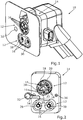
- a charging socket 10 for a motor vehicle is in a perspective view in Fig. 1 shown.
- the charging socket 10 is installed on the vehicle side and is used to receive a charging plug, not shown here, by means of which a battery of the motor vehicle can be charged, which can be a fully electric vehicle or a plug-in hybrid, for example.
- the charging socket 10 comprises a plug interface 12, which is part of a contact housing 14 of the charging socket 10.
- An unspecified upper area of the plug interface 12 comprises five receiving openings 16 and a lower unspecified area of the plug interface 12 also comprises two further receiving openings 16 for receiving respective contact pins, not specified here, which are used to charge the battery of the motor vehicle with the charging plug are contactable.
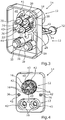
- Fig. 2 is a front view of the contact housing 14 is shown in a perspective view, within which the connector interface 12 is clearly visible again.
- the contact pin 18 can be, for example, a positive pole for one Trade AC connection.
- the contact pin 20 can be a negative pole of the AC connection, and the contact pin 22 can be a protective conductor or a grounding of the AC connection.
- the contact pin 24 is, for example, a signal contact for interface communication between the charging socket 10 and the motor vehicle in question.
- the contact pin 26 can be a signal contact for communication with the charging station in question, a so-called proximity pilot.
- the contact pin 28 can be, for example, a positive pole of a direct current connection and the contact pin 30 can be a negative pole of the direct current connection.
- a lighting device 32 can also be seen, which is attached to the contact housing 14 and can be part of the charging socket 10.
- the lighting device 32 is supplied with light by a light guide 34.
- the lighting device 32 can ensure, for example, in the dark or in poor visibility conditions that a user can position and insert the charging plug in a particularly simple manner at the plug interface 12.
- the charging socket 10 can have a plurality of these lighting devices 32 and light guides 34, with further receiving openings 36 being provided for each light guide 34.
- the receiving openings 16 and 36 should be sealed such that when the contact pins 18 to 26 or 28 to 30 are mounted and the light guides 34 are installed, no dust and / or liquids can penetrate into the interior of the charging socket 10.
- Fig. 3 the contact housing 14 is shown in a perspective rear view.
- the contact pins 18 to 26 and 28, 30 and the light guide 34 can be seen again on the back.
- respective sleeve-like receptacles 38 are provided for the contact pins 18 to 22 and 28, 30, respective sleeve-like receptacles 38 are provided.
- the contact housing 14 is a two-component injection-molded part, the main body 40 of which is produced from a first component, which is not specified in any more detail, with respective sealing regions 42 (here only partially recognizable) formed as borders of the receiving openings 16 and 36 being produced from a second component 41, which are more elastic and / or softer than the first component.
- the second component 41 is not only provided directly in the region of the receiving openings 16, 36.
- the second component 41 can be an elastomer, for example, whereas the first component can be a thermoplastic, for example.
- the main body 40 of the contact housing 14 comprises a channel system, which is not described in any more detail here, and which comprises a plurality of grooves, which are not specified in more detail and which extend from at least one injection point 44 for the second component 41 to the respective receiving openings 16, 36 and are filled in by the second component 41 .
- Fig. 4 is the contact housing 14 from the same perspective as in Fig. 2 shown, wherein all contact pins 18 to 26, 28, 30 and the lighting device 32 including light guide 34 have been omitted.
- the receiving openings 16, 36 for the contact pins 18 to 26 and 28 to 30 and for the light guide 34 can be clearly seen.
- this illustration clearly shows the sealing areas 42 formed from the second component 41, which surround the receiving openings 16 and 36, respectively.
- the receiving openings 16, 36 are round in the present case and the sealing regions 42 correspondingly at least substantially in the form of a ring. This is because the contact pins 18 to 26, 28, 30 and the light guide 34 have a round cross section in the present case. It is essential that the geometry of the receiving openings 16, 36 and thus also the sealing areas 42 is adapted to the cross-sectional shape of the contact pins 18 to 26, 28, 30 and the light guide 34 in order to achieve a positive fit and thus a good sealing effect.
- the sealing areas 42 enclose these elements, for example, dust-tight and liquid-tight. Because the second component 41 is softer than the first component from which the main body 40 of the contact housing 14 is made, a sealing effect can be achieved in a particularly reliable manner.
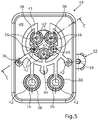
- Fig. 5 the contact housing 14 is shown in a front view from the rear.
- the arrangement of the second component 41 within the main body 40 can again be clearly seen here.
- the second component 41 extends in a channel-like manner to the respective receiving openings 16 and 36, which are enclosed by the sealing regions 42 which are formed from the second component 41.
- the contact housing 14 is produced by means of an injection mold, not shown here, in a two-component injection molding process. First, the Main body 40 of the contact housing 14 made of the first component.
- the second component 41 is then injected into the injection mold at the injection point 44. Starting from the injection point 44, the injected second component is then distributed as far as the receiving openings 16 and 36, where it forms the said sealing regions 42.
- respective movable cores of said injection mold can be arranged such that the first component is used to produce the main body 40 with said channel system from the plurality of grooves in accordance with the arrangement of the cores.
- the cores are then moved out of the grooves - perpendicular to the plane of the drawing in accordance with the present illustration - that a cavity is enclosed between the cores and grooves, in which, starting from the injection point 44 of the channel system, the second component 41 is injected to form the sealing areas 42.
- the cores can also be moved relative to the main body 40 of the contact housing 14, for example to remove excess material from the second component 41. If one or more of the receiving openings 16 or 36 are to be closed, it is also possible that the cores in question are designed and / or arranged such that the relevant receiving openings 16, 36 are completely closed by the injected second component 41 will and will remain.
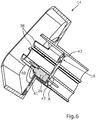
- Fig. 6 11 is a partially sectioned perspective view along the line in FIG Fig. 5 marked section plane CC shown.
- the second component 41 which serves as a sealing material, extends within the grooves of the channel system of the main body 40, which are likewise not described here, as far as the respective receiving openings 16, in which only one is shown in the present illustration the contact pins 26 is shown and arranged.
- the second component 41 Due to the good sealing and elastic properties of the second component 41, it is possible in a simple manner to seal the charging socket 10 around the contact pins 18 to 26 or 28, 30 and the light guide 34. in the In the course of the manufacture of the contact housing 14, it is also not necessary to first assemble and test the sealing areas 42 from separate parts, for example silicone inserts or the like, in a complex manner. Instead, it is possible by means of a manufacturing process, namely by means of the two-component injection molding method, to produce the sealing areas 42 as an integral part of the contact housing 14.
- Fig. 7 is the in Fig. 6 area A shown in a detailed view, a first embodiment of a sealing structure 46 of the sealing area 42 shown here by way of example being shown.
- the sealing area 42 comprises a sealing structure 46 which is raised radially inwards and axially and which is in the present case in the form of essentially triangular or pyramid-shaped elevations. This enables a particularly good sealing effect to be achieved.
- Fig. 8 is the in Fig. 6 area A shown in a further detailed view, a second possible embodiment of the sealing structure 46 is shown.
- the sealing structure 46 comprises a plurality of hemispherical elements 50, which are likewise designed to be radially inward and axially raised. A particularly good sealing effect can also be achieved in this way.
- the contact housing 14 is not only limited to the specific connector interface 12 shown in the figures.
- the principle described can be transferred to different numbers of contact pins and differently designed plug interfaces 12 in order to achieve a particularly simple and reliable sealing effect in the area of the receiving openings 16 and 36.
Landscapes
- Engineering & Computer Science (AREA)
- Manufacturing & Machinery (AREA)
- Mechanical Engineering (AREA)
- Power Engineering (AREA)
- Transportation (AREA)
- Chemical & Material Sciences (AREA)
- Dispersion Chemistry (AREA)
- Connector Housings Or Holding Contact Members (AREA)
Abstract
Description
- Die Erfindung betrifft ein Kontaktgehäuse für eine Ladedose eines Kraftfahrzeugs, eine Ladedose für ein Kraftfahrzeug sowie ein Verfahren zum Herstellen einer Ladedose eines Kraftfahrzeugs.
- Rein elektrisch angetriebene Kraftfahrzeuge oder Plug-In-Hybridfahrzeuge weisen üblicherweise eine Ladedose auf, mit welcher ein Ladestecker zum Aufladen einer Batterie des betreffenden Fahrzeugs verbunden werden kann. Derartige Ladedosen weisen je nach verwendetem Steckertyp unterschiedliche stromführende und signalführende Kontaktstifte auf, die beim Aufladen der betreffenden Batterie mit entsprechenden Elementen des jeweiligen Ladesteckers kontaktiert werden. Derartige Ladedosen sind meistens hinter verschwenkbaren Klappen der betreffenden Fahrzeuge verborgen. Sobald ein Ladestecker in die Ladedose gesteckt werden soll, muss eine solche Klappe geöffnet werden, in Folge dessen die betreffende Ladedose unterschiedlichen Umwelteinflüssen, wie beispielsweise Feuchtigkeit oder Staub ausgesetzt werden kann. Da die Ladedose selbst u.a. in Form der Kontaktstifte stromführende Teile aufweist, ist es wünschenswert, dass die Ladedose insbesondere im Bereich der Kontaktstifte besonders gut gegen Staubeintritt oder Flüssigkeitseintritt geschützt wird.
- Es ist die Aufgabe der vorliegenden Erfindung, eine besonders einfache und zuverlässige Abdichtung einer Ladedose eines Kraftfahrzeugs zu ermöglichen.
- Diese Aufgabe wird durch ein Kontaktgehäuse für eine Ladedose eines Kraftfahrzeugs sowie durch ein Verfahren zum Herstellen einer Ladedose eines Kraftfahrzeugs mit den Merkmalen der unabhängigen Patentansprüche gelöst. Vorteilhafte Ausgestaltungen mit zweckmäßigen und nicht trivialen Weiterbildungen der Erfindung sind in den abhängigen Ansprüchen angegeben.
- Das erfindungsgemäße Kontaktgehäuse für eine Ladedose eines Kraftfahrzeugs umfasst eine Steckerschnittstelle mit mehreren Aufnahmeöffnungen zum Aufnehmen jeweiliger Kontaktstifte, die zum Aufladen einer Batterie des Kraftfahrzeugs mit einem Ladestecker kontaktierbar sind, wobei das Kontaktgehäuse ein Mehrkomponentenspritzgussteil ist, dessen Hauptkörper aus einer ersten Komponente hergestellt ist, und zumindest jeweilige Umrandungen der Aufnahmeöffnungen bildende Dichtungsbereiche aus einer zweiten Komponente hergestellt sind, die elastischer als die erste Komponente ist. Vorzugsweise ist die zweite Komponente auch weicher als die erste Komponente. Die zweite Komponente fungiert als Dichtungswerkstoff, der die jeweiligen Umrandungen der Aufnahmeöffnungen in Form der Dichtungsbereiche bildet. Nachdem die Kontaktstifte in ihrer bestimmungsgemäßen Weise innerhalb der Aufnahmeöffnungen des Kontaktgehäuses montiert worden sind, umschließen die Dichtungsbereiche, welche aus der zweiten elastischen und vorzugsweise weichen Komponente hergestellt sind, die entsprechenden Kontaktstifte formschlüssig. Bei fertig montierter Ladedose kann in dem Fall also vorzugsweise weder Staub noch Flüssigkeit im Bereich der Kontaktstifte in die Ladedose eindringen.
- Bei den Kontaktstiften kann es sich sowohl um stromführende Kontakte handeln, welche zum Aufladen der besagten Batterie dienen, als auch um signalführende Kontakte, wie einen sogenannten Proximity-Pilot bzw. Control-Pilot.
- Bei dem Kontaktgehäuse handelt es sich also zumindest um ein Zweikomponentenspritzgussteil aus der besagten ersten Komponente und zweiten Komponente. Bei dem erfindungsgemäßen Kontaktgehäuse wird eine dauerhafte und zuverlässige Abdichtung des Kontaktgehäuses und somit der Ladedose im Bereich der Kontaktstifte ermöglicht. Zudem können die Dichtungsbereiche besonders einfach hergestellt werden, da diese im Zuge des Mehrkomponentenspritzgussverfahrens auf einfache Weise hergestellt werden können. Die Dichtungsbereiche sind keine separaten Teile bzw. Elemente, welche erst aufwendig montiert und überprüft werden müssen. Dadurch ergibt sich im Hinblick auf eine Herstellung des Kontaktgehäuses auch eine besonders prozesssichere Abdichtungsmöglichkeit der besagten Kontaktstifte im montierten Zustand. Das erfindungsgemäße Kontaktgehäuse stellt also eine besonders einfache und zuverlässige Abdichtung im Bereich der Kontaktstifte sicher.
- Eine vorteilhafte Ausführungsform der Erfindung sieht vor, dass die zweite Komponente aus einem Elastomer hergestellt ist. Es können auch andere elastische Dichtmaterialien für die zweite Komponente verwendet werden. Bei der ersten Komponente kann es sich beispielsweise um einen Thermoplast handeln. Die erste Komponente sorgt für die Aufnahme von Kräften und für eine ausreichende Formstabilität des Kontaktgehäuses, wohingegen die zweite Komponente vor allem die besagte Abdichtwirkung rund um die Kontaktstifte im montierten Zustand bewirkt. Durch eine geeignete Materialauswahl betreffend die erste und zweite Komponente können sowohl mechanische als auch abdichtende Eigenschaften gleichermaßen mittels des Kontaktgehäuses erfüllt werden.
- Eine weitere vorteilhafte Ausführungsform der Erfindung sieht vor, dass das Kontaktgehäuse außerhalb der Steckerschnittstelle wenigstens eine weitere Aufnahmeöffnung zum Aufnehmen eines Lichtleiters für eine Beleuchtungseinrichtung der Ladedose aufweist, wobei diese Aufnahmeöffnung ebenfalls von einem aus der zweiten Komponente hergestellten Dichtungsbereich umschlossen ist. Die Beleuchtungseinrichtung kann z.B. dazu dienen, während eines Ladevorgangs die Ladedose ausreichend auszuleuchten oder kann auch als Informations- oder Signalleuchte dienen, z.B. um einen Ladezustand anzuzeigen oder einen Ladevorgang zu signalisieren. Dadurch, dass das Kontaktgehäuse außerhalb der Steckerschnittstelle die wenigstens eine weitere Aufnahmeöffnung zum Aufnehmen des Lichtleiters für die Beleuchtungseinrichtung aufweist, kann die besagte Beleuchtungseinrichtung besonders einfach mit Licht versorgt werden. Dadurch, dass diese Aufnahmeöffnung ebenfalls von dem aus der zweiten Komponente hergestellten Dichtungsbereich umschlossen ist, kann auch in diesem Bereich zuverlässig verhindert werden, dass Staub und/oder Flüssigkeit ins Innere der Ladedose eindringt.
- Gemäß einer weiteren vorteilhaften Ausführungsform der Erfindung ist es vorgesehen, dass wenigstens einer der Dichtungsbereiche eine nach radial innen und/oder axial erhabene Dichtstruktur aufweist. Die Struktur kann beispielsweise halbkugelförmige oder lamellenförmige Elemente aufweisen. Um eine besonders zuverlässige Abdichtung zu erzielen, kann es vorgesehen sein, dass auf Umfangsflächen oder auch stirnseitigen Flächen bei zumindest einem der Dichtungsbereiche zum Beispiel Gummilippen oder anderweitige erhabene Dichtstrukturen vorgesehen sind. Dadurch kann der betreffende Kontaktstift oder Lichtleiter besonders zuverlässig gegen Staubeintritt und/oder Flüssigkeitseintritt abgedichtet werden. Auch ist es möglich, dass alle Dichtungsbereiche mit dieser Dichtstruktur versehen sind.
- Eine weitere vorteilhafte Ausführungsform der Erfindung sieht vor, dass der Hauptkörper des Kontaktgehäuses ein Kanalsystem aus mehreren Nuten aufweist, welche sich ausgehend von zumindest einem Anspritzpunkt für die zweite Komponente bis zu den jeweiligen Aufnahmeöffnungen erstrecken und von der zweiten Komponente ausgefüllt sind. Mit anderen Worten ist in Form des aus den Nuten bestehenden Kanalsystems eine definierte Kontur in den Hauptkörper des Kontaktgehäuses eingebracht, welche von der zweiten Komponente ausgefüllt ist. Das Kanalsystem dient während eines Spritzgussvorgangs dazu, ausgehend vom besagten Anspritzpunkt die zweite Komponente einzuspritzen, wobei diese sich entlang des Kanalsystems bis zu den jeweiligen Aufnahmeöffnungen fortbewegen kann, um dann die besagten Umrandungen auszubilden, welche als Dichtungsbereiche fungieren. Das Kanalsystem aus den Nuten ist dabei so gestaltet, dass sich ein besonders zuverlässiger Einspritz- und Verteilvorgang der zweiten Komponente realisieren lässt.
- Die erfindungsgemäße Ladedose für ein Kraftfahrzeug umfasst das erfindungsgemäße Kontaktgehäuse oder eine vorteilhafte Ausführungsform des erfindungsgemäßen Kontaktgehäuses, wobei durch die Aufnahmeöffnungen der Steckerschnittstelle jeweilige Kontaktstifte der Ladedose hindurchgeführt und von den die jeweiligen Umrandungen der Aufnahmeöffnungen bildenden Dichtungsbereiche des Kontaktgehäuses umschlossen sind. Im fertig montierten Zustand der Ladedose kommen also die aus der zweiten Komponente hergestellten Dichtungsbereiche zum Tragen, welche die jeweiligen Kontaktstifte umschließen und so die Ladedose in diesen Bereichen gegenüber einem Flüssigkeitseintritt und/oder Staubeintritt zuverlässig abdichten.
- Bei dem erfindungsgemäßen Verfahren zum Herstellen einer Ladedose eines Kraftfahrzeugs, umfassend ein Kontaktgehäuse, welches eine Steckerschnittstelle mit mehreren Aufnahmeöffnungen zum Aufnehmen jeweiliger Kontaktstifte der Ladedose aufweist, die zum Aufladen einer Batterie des Kraftfahrzeugs mit einem Ladestecker kontaktierbar sind, wird das Kontaktgehäuse mittels eines Spritzgießwerkzeugs in einem Mehrkomponentenspritzgussverfahren hergestellt, indem ein Hauptkörper des Kontaktgehäuses aus einer ersten Komponente und zumindest jeweilige Umrandungen der Aufnahmeöffnungen bildende Dichtungsbereiche aus einer zweiten Komponente hergestellt werden, welche elastischer als die erste Komponente ist. Vorteilhafte Ausgestaltungen des erfindungsgemäßen Kontaktgehäuses bzw. der erfindungsgemäßen Ladedose sind als vorteilhafte Ausgestaltungen des erfindungsgemäßen Verfahrens und umgekehrt anzusehen. Mittels des erfindungsgemäßen Verfahrens kann insbesondere das erfindungsgemäße Kontaktgehäuse oder eine vorteilhafte Ausführungsform des erfindungsgemäßen Kontaktgehäuses besonders einfach und zuverlässig hergestellt werden. Dadurch, dass ein Mehrkomponentenspritzgussverfahren, insbesondere ein Zweikomponentenspritzgussverfahren, zum Einsatz kommt, können die Dichtungsbereiche aus der zweiten Komponente auf einfache Weise als integraler Bestandteil des Kontaktgehäuses hergestellt werden. Aufwendige Montagetätigkeiten zur Anbringung von anderweitigen separaten Dichtungen, beispielsweise Silikondichtungen oder dergleichen, können bei dem erfindungsgemäßen Verfahren entfallen. Dadurch lässt sich besonders prozesssicher, schnell und kostengünstig eine zuverlässige Abdichtwirkung insbesondere rund um die Kontaktstifte der Ladedose realisieren.
- Eine vorteilhafte Ausführungsform des erfindungsgemäßen Verfahrens sieht vor, dass nach dem Herstellen des Kontaktgehäuses die jeweiligen Kontaktstifte durch die von den Dichtungsbereichen umschlossenen Aufnahmeöffnungen hindurchgeführt und innerhalb der Steckerschnittstelle angeordnet werden. Nachdem also das Kontaktgehäuse durch das Mehrkomponentenspritzgussverfahren hergestellt worden ist, erfolgt die eigentliche Montage der Ladedose, wobei dabei unter anderem die jeweiligen Kontaktstifte durch die von den Dichtungsbereichen umschlossenen Aufnahmeöffnungen hindurchgeführt und innerhalb der Steckerschnittstelle angeordnet werden. Die Dichtungsbereiche aus der zweiten Komponente, bei welcher es sich vorzugsweise um ein besonders geeignetes Dichtungsmaterial handelt, umschließen nach der bestimmungsgemäßen Anordnung der Kontaktstifte innerhalb der Steckerschnittstelle die Kontaktstifte flüssigkeitsdicht und/oder staubdicht. Mittels der ins Kontaktgehäuse integrierten Dichtungsbereiche können so die montierten Kontaktstifte zuverlässig umschlossen werden, um eine hinreichende Abdichtwirkung in diesem Bereich der Ladedose zu erzielen.
- Gemäß einer weiteren vorteilhaften Ausführungsform des erfindungsgemäßen Verfahrens ist es vorgesehen, dass vor einem Einspritzen der ersten Komponente in das Spritzgießwerkzeug jeweilige bewegliche Kerne des Spritzgießwerkzeugs so angeordnet werden, dass aus der ersten Komponente ein Hauptkörper des Kontaktgehäuses mit einem Kanalsystem aus mehreren Nuten gemäß der Anordnung der Kerne hergestellt wird, wonach die Kerne so aus den Nuten herausbewegt werden, dass zwischen den Kernen und Nuten ein Hohlraum eingeschlossen wird, in welchen ausgehend von zumindest einem Anspritzpunkt des Kanalsystems die zweite Komponente unter Ausbildung der Dichtungsbereiche eingespritzt wird. Mittels der beweglichen Kerne wird also das besagte Kanalsystem innerhalb des Hauptkörpers des Kontaktgehäuses hergestellt bzw. realisiert, welcher aus der ersten Komponente durch Spritzguss hergestellt wird. Nachdem innerhalb des Spritzgießwerkzeugs der Hauptkörper des Kontaktgehäuses mit dem besagten Kanalsystem hergestellt worden ist, werden sodann die beweglichen Kerne soweit aus den Nuten des Kanalsystems herausbewegt, dass ein entsprechender Hohlraum bereitgestellt wird, in welchen dann ausgehend von dem zumindest einen Anspritzpunkt des Kanalsystems die zweite Komponente unter Ausbildung der Dichtungsbereiche eingespritzt wird. So kann die zweite Komponente bis zu den gewünschten und herzustellenden Dichtungsbereichen gelangen. Anschließend kann das fertighergestellte Kontaktgehäuse aus dem Spritzgießwerkzeug entformt werden. Das Kanalsystem im Hauptkörper stellt also jeweilige Fließwege bis zu den Aufnahmeöffnungen sicher, wo die zweite Komponente als Dichtung fungieren soll.
- In weiterer vorteilhafter Ausgestaltung des erfindungsgemäßen Verfahrens ist es vorgesehen, dass zumindest ein Teil der Kerne nach dem Einspritzen der zweiten Komponente zum Entfernen von überschüssigem Material der zweiten Komponente relativ zum Hauptkörper des Kontaktgehäuses bewegt wird. So können beispielsweise Grate oder anderweitig überstehende Bereiche der zweiten Komponente auf einfache Weise mittels der beweglichen Kerne entfernt werden.
- Schließlich sieht eine weitere vorteilhafte Ausführungsform des erfindungsgemäßen Verfahrens vor, dass zumindest einer der Kerne so ausgestaltet ist und/oder angeordnet wird, dass wenigstens eine der Aufnahmeöffnungen durch die eingespritzte zweite Komponente vollständig verschlossen wird. Je nachdem, wie viele Aufnahmeöffnungen tatsächlich erforderlich sind, ist es so auf einfache Weise möglich, nicht benötigte Aufnahmeöffnungen einfach durch die eingespritzte zweite Komponente zu verschließen. Bei unterschiedlichen Varianten an erforderlichen Aufnahmeöffnungen muss so nicht das gesamte Spritzgießwerkzeug umgestaltet werden. Lediglich die Bewegung der betreffenden Kerne wird angepasst, je nachdem welche der Aufnahmeöffnungen gegebenenfalls durch die eingespritzte zweite Komponente vollständig verschlossen bleiben sollen.
- Weitere Vorteile, Merkmale und Einzelheiten der Erfindung ergeben sich aus der nachfolgenden Beschreibung bevorzugter Ausführungsbeispiele sowie anhand der Zeichnung. Die vorstehend in der Beschreibung genannten Merkmale und Merkmalskombinationen sowie die nachfolgend in der Figurenbeschreibung und/oder in den Figuren alleine gezeigten Merkmale und Merkmalskombinationen sind nicht nur in der jeweils angegebenen Kombination, sondern auch in anderen Kombinationen oder in Alleinstellung verwendbar, ohne den Rahmen der Erfindung zu verlassen.
- Die Zeichnung zeigt in:
- Fig. 1
- eine Perspektivansicht einer Ladedose eines Kraftfahrzeugs, umfassend ein Kontaktgehäuse mit einer Steckerschnittstelle, die mehrere Aufnahmeöffnungen zum Aufnehmen eines Ladesteckers aufweist;
- Fig. 2
- eine perspektivische Ansicht auf eine Vorderseite des Kontaktgehäuses, wobei mehrere Kontaktstifte der Ladedose in zwei Bereichen der Steckerschnittstelle angeordnet sind;
- Fig. 3
- eine perspektivische Ansicht auf eine Rückseite des Kontaktgehäuses mit den darin angeordneten Kontaktstiften;
- Fig. 4
- eine weitere perspektivische Ansicht auf die Vorderseite des Kontaktgehäuses, wobei die Kontaktstifte nicht dargestellt sind;
- Fig. 5
- eine Draufsicht auf eine von der Steckerschnittstelle des Kontaktgehäuses abgewandte Rückseite;
- Fig. 6
- eine teilweise geschnittene Perspektivansicht des Kontaktgehäuses entlang der in
Fig. 5 gekennzeichneten Schnittebene C-C; - Fig. 7
- eine Detailansicht des in
Fig. 6 gekennzeichneten Bereichs A, wobei eine erste Ausführungsform eines Dichtungsbereichs dargestellt ist; und in - Fig. 8
- eine weitere Detailansicht des in
Fig. 6 gekennzeichneten Bereichs A, wobei eine zweite Ausführungsform des Dichtungsbereichs dargestellt ist. - In den Figuren sind gleiche oder funktionsgleiche Elemente mit den gleichen Bezugszeichen versehen worden.
- Eine Ladedose 10 für ein Kraftfahrzeug ist in einer Perspektivansicht in
Fig. 1 gezeigt. Die Ladedose 10 wird fahrzeugseitig verbaut und dient zum Aufnehmen eines hier nicht dargestellten Ladesteckers, mittels welchem eine Batterie des Kraftfahrzeugs aufgeladen werden kann, bei welchem es sich beispielsweise um ein vollelektrisches Fahrzeug oder auch um einen Plug-In-Hybrid handeln kann. Zum Aufnehmen des hier nicht dargestellten Ladesteckers umfasst die Ladedose 10 eine Steckerschnittstelle 12, welche Teil eines Kontaktgehäuses 14 der Ladedose 10 ist. Ein nicht näher bezeichneter oberer Bereich der Steckerschnittstelle 12 umfasst fünf Aufnahmeöffnungen 16 und ein unterer nicht näher bezeichneter Bereich der Steckerschnittstelle 12 umfasst zudem noch zwei weitere Aufnahmeöffnungen 16 zum Aufnehmen jeweiliger hier nicht näher bezeichneter Kontaktstifte, die zum Aufladen der besagten Batterie des Kraftfahrzeugs mit dem Ladestecker kontaktierbar sind. - In
Fig. 2 ist eine Vorderseite des Kontaktgehäuses 14 in einer Perspektivansicht gezeigt, innerhalb welcher die Steckerschnittstelle 12 nochmals gut zu erkennen ist. In dem kreisförmigen oberen Bereich der Steckerschnittstelle 12 sind mehrere mittels der Aufnahmeöffnung 16 aufgenommene Kontaktstifte 18, 20, 22, 24, 26 zu erkennen. Bei dem Kontaktstift 18 kann es sich beispielsweise um einen Pluspol für einen Wechselstromanschluss handeln. Bei dem Kontaktstift 20 kann es sich um einen Minuspol des Wechselstromanschlusses handeln, wobei es sich bei dem Kontaktstift 22 um einen Schutzleiter bzw. eine Erdung des Wechselstromanschlusses handeln kann. Bei dem Kontaktstift 24 handelt es sich beispielsweise um einen Signalkontakt zur Schnittstellenkommunikation zwischen der Ladedose 10 und dem betreffenden Kraftfahrzeug. Bei dem Kontaktstift 26 kann es sich um einen Signalkontakt zur Kommunikation mit der betreffenden Ladesäule handeln, einem sogenannten Proximity-Pilot. - In dem eher ovalen unteren Bereich der Steckerschnittstelle 12 sind noch weitere Kontaktstifte 28, 30 zu erkennen. Bei dem Kontaktstift 28 kann es sich beispielsweise um einen Pluspol eines Gleichstromanschlusses und bei dem Kontaktstift 30 um einen Minuspol des Gleichstromanschlusses handeln. Zudem ist noch eine Beleuchtungseinrichtung 32 zu erkennen, welche am Kontaktgehäuse 14 angebracht ist und ein Teil der Ladedose 10 sein kann. Die Beleuchtungseinrichtung 32 wird von einem Lichtleiter 34 mit Licht versorgt. Die Beleuchtungseinrichtung 32 kann beispielsweise im Dunkeln oder bei schlechten Sichtverhältnissen dafür sorgen, dass ein Benutzer den besagten Ladestecker besonders einfach passend an der Steckerschnittstelle 12 positionieren und einstecken kann. Die Ladedose 10 kann mehrere dieser Beleuchtungseinrichtungen 32 und Lichtleiter 34 aufweisen, wobei je Lichtleiter 34 weitere Aufnahmeöffnungen 36 vorgesehen sind. Die Aufnahmeöffnungen 16 und 36 sollten so abgedichtet sein, dass bei montierten Kontaktstiften 18 bis 26 bzw. 28 bis 30 und montierten Lichtleitern 34 kein Staub und/oder Flüssigkeiten ins Innere der Ladedose 10 eindringen können.
- In
Fig. 3 ist das Kontaktgehäuse 14 in einer perspektivischen Rückansicht gezeigt. Hier sind rückseitig nochmals die besagten Kontaktstifte 18 bis 26 und 28, 30 sowie der Lichtleiter 34 zu erkennen. Für die Kontaktstifte 18 bis 22 und 28, 30 sind jeweilige hülsenartige Aufnahmen 38 vorgesehen. - Das Kontaktgehäuse 14 ist ein Zweikomponentenspritzgussteil, dessen Hauptkörper 40 aus einer ersten nicht näher bezeichneten Komponente hergestellt ist, wobei jeweilige als Umrandungen der Aufnahmeöffnungen 16 bzw. 36 ausgebildete Dichtungsbereiche 42 (hier nur teilweise zu erkennen) aus einer zweiten Komponente 41 hergestellt sind, die elastischer und/oder weicher als die erste Komponente ist. Die zweite Komponente 41 ist, wie zu erkennen, nicht nur unmittelbar im Bereich der Aufnahmeöffnungen, 16, 36 vorgesehen. Die zweite Komponente 41 kann beispielsweise ein Elastomer sein, wohingegen die erste Komponente beispielsweise ein Thermoplast sein kann. Der Hauptkörper 40 des Kontaktgehäuses 14 umfasst ein hier nicht näher bezeichnetes Kanalsystem aus mehreren nicht näher bezeichneten Nuten, welche sich ausgehend von zumindest einem Anspritzpunkt 44 für die zweite Komponente 41 bis zu den jeweiligen Aufnahmeöffnungen 16, 36 erstrecken und von der zweiten Komponente 41 ausgefüllt sind.
- In
Fig. 4 ist das Kontaktgehäuse 14 aus der gleichen Perspektive wie inFig. 2 gezeigt, wobei sämtliche Kontaktstifte 18 bis 26, 28, 30 sowie die Beleuchtungseinrichtung 32 inklusive Lichtleiter 34 weggelassen worden sind. In der vorliegenden Darstellung sind aufgrund der weggelassenen Kontaktstifte 18 bis 26, 28, 30 die Aufnahmeöffnungen 16, 36 für die Kontaktstifte 18 bis 26 sowie 28 bis 30 sowie für den Lichtleiter 34 gut zu erkennen. Des Weiteren kann man in dieser Darstellung gut die aus der zweiten Komponente 41 gebildeten Dichtungsbereiche 42 erkennen, welche die Aufnahmeöffnungen 16 bzw. 36 umgeben. Die Aufnahmeöffnungen 16, 36 sind vorliegend rund und die Dichtungsbereiche 42 entsprechend zumindest im Wesentlichen kreisringförmig. Das liegt daran, dass die Kontaktstifte 18 bis 26, 28, 30 und der Lichtleiter 34 vorliegend einen runden Querschnitt aufweisen. Wesentlich ist, dass die Geometrie der Aufnahmeöffnungen 16, 36 und somit auch der Dichtungsbereiche 42 an die Querschnittsform der Kontaktstifte 18 bis 26, 28, 30 und des Lichtleiters 34 angepasst ist, um einen Formschluss und somit eine gute Abdichtwirkung zu erzielen. - Im montierten Zustand der Kontaktstifte 18 bis 26 sowie 28, 30 und im montierten Zustand des Lichtleiters 34 umschließen die Dichtungsbereiche 42 diese Elemente beispielsweise staubdicht und flüssigkeitsdicht. Dadurch, dass die zweite Komponente 41 weicher als die erste Komponente ist, aus welchem der Hauptkörper 40 des Kontaktgehäuses 14 hergestellt ist, kann auf besonders zuverlässige Weise eine Dichtwirkung erzielt werden.
- In
Fig. 5 ist das Kontaktgehäuse 14 in einer Frontalansicht von hinten gezeigt. Hier kann man nochmal gut die Anordnung der zweiten Komponente 41 innerhalb des Hauptkörpers 40 erkennen. Ausgehend vom besagten Anspritzpunkt 44 erstreckt sich die zweite Komponente 41 kanalartig bis zu den jeweiligen Aufnahmeöffnungen 16 bzw. 36, welche durch die Dichtungsbereiche 42 umschlossen sind, die aus der zweiten Komponente 41 gebildet sind. Das Kontaktgehäuse 14 wird mittels eines hier nicht dargestellten Spritzgießwerkzeugs in einem Zweikomponentenspritzgussverfahren hergestellt. Zunächst wird dabei der Hauptkörper 40 des Kontaktgehäuses 14 aus der ersten Komponente hergestellt. Anschließend wird die zweite Komponente 41 am Anspritzpunkt 44 in das Spritzgießwerkzeug eingespritzt. Ausgehend vom Anspritzpunkt 44 verteilt sich die eingespritzte zweite Komponente dann bis zu den Aufnahmeöffnungen 16 bzw. 36 und bildet dort die besagten Dichtungsbereiche 42 aus. - Vor dem Einspritzen der ersten Komponente, aus welcher der Hauptkörper 40 hergestellt wird, können jeweilige bewegliche Kerne des besagten Spritzgießwerkzeugs so angeordnet werden, dass aus der ersten Komponente der Hauptkörper 40 mit dem besagten Kanalsystem aus den mehreren Nuten gemäß der Anordnung der Kerne hergestellt wird. Danach werden die Kerne so aus den Nuten herausbewegt - gemäß der vorliegenden Darstellung also senkrecht zur Zeichnungsebene - das zwischen den Kernen und Nuten ein Hohlraum eingeschlossen wird, in welchen ausgehend vom Anspritzpunkt 44 des Kanalsystems die zweite Komponente 41 unter Ausbildung der Dichtungsbereiche 42 eingespritzt wird. Die Kerne können nach dem Einspritzen der zweiten Komponente 41 beispielsweise auch zum Entfernen von überschüssigem Material der zweiten Komponente 41 relativ zum Hauptkörper 40 des Kontaktgehäuses 14 bewegt werden. Falls eine oder auch mehrere der Aufnahmeöffnungen 16 bzw. 36 verschlossen werden sollen, so ist es auch möglich, dass die betreffenden Kerne so ausgestaltet sind und/oder so angeordnet werden, dass die betreffenden Aufnahmeöffnungen 16, 36 durch die eingespritzte zweite Komponente 41 vollständig verschlossen werden und bleiben.
- In
Fig. 6 ist das Kontaktgehäuse 14 in einer teilweise geschnittenen Perspektivansicht entlang der inFig. 5 gekennzeichneten Schnittebene C-C gezeigt. In der vorliegenden Darstellung kann man gut erkennen, wie sich die zweite Komponente 41, welche als Dichtmaterial dient, innerhalb der hier ebenfalls nicht näher bezeichneten Nuten des Kanalsystems des Hauptkörpers 40 bis zu den jeweiligen Aufnahmeöffnungen 16 erstreckt, in denen in der vorliegenden Darstellung nur einer der Kontaktstifte 26 dargestellt und angeordnet ist. Durch entsprechende Ausgestaltung und Bewegung der besagten Kerne des Spritzgießwerkzeugs ist es möglich, im Zweikomponentenspritzgießverfahren zunächst den Hauptkörper 40 aus der ersten Komponente und anschließend die Dichtungsbereiche 42 aus der ersten Komponente herzustellen. Durch die gut abdichtenden und elastischen Eigenschaften der zweiten Komponente 41 ist es auf einfache Weise möglich, die Ladedose 10 rund um die Kontaktstifte 18 bis 26 bzw. 28, 30 sowie die Lichtleiter 34 abzudichten. Im Zuge der Herstellung des Kontaktgehäuses 14 ist es zudem nicht erforderlich, die Dichtungsbereiche 42 aus separaten Teilen, beispielsweise Silikoneinlegern oder dergleichen, erst aufwendig zu montieren und zu prüfen. Stattdessen ist es mittels eines Herstellungsvorgangs, nämlich mittels des Zweikomponentenspritzgussverfahrens, möglich, die Dichtungsbereiche 42 als integralen Bestandteil des Kontaktgehäuses 14 herzustellen. - In
Fig. 7 ist der inFig. 6 gekennzeichnete Bereich A in einer Detailansicht gezeigt, wobei eine erste Ausführungsform einer Dichtstruktur 46 des hier exemplarisch gezeigten Dichtungsbereichs 42 dargestellt ist. Der Dichtungsbereich 42 umfasst vorliegend eine nach radial innen und axial erhabene Dichtstruktur 46, welche vorliegend in Form von im Wesentlichen dreiecksförmigen bzw. pyramidenförmigen Erhebungen ausgebildet ist. Dadurch kann eine besonders gute Abdichtwirkung erzielt werden. - In
Fig. 8 ist der inFig. 6 gekennzeichnete Bereich A in einer weiteren Detailansicht gezeigt, wobei eine zweite mögliche Ausführungsform der Dichtstruktur 46 dargestellt ist. Im vorliegend gezeigten Fall umfasst die Dichtstruktur 46 mehrere halbkugelförmige Elemente 50, welche ebenfalls nach radial innen und axial erhaben ausgebildet sind. Dadurch kann ebenfalls eine besonders gute Abdichtwirkung erreicht werden. - Das Kontaktgehäuse 14 als Mehrkomponentenspritzgussteil, insbesondere als Zweikomponentenspritzgussteil, herzustellen, um die integrierten Dichtungsbereiche 42 zu realisieren, ist nicht nur auf die in den Figuren gezeigte konkrete Steckerschnittstelle 12 beschränkt. Das beschriebene Prinzip kann auf unterschiedlich viele Kontaktstifte und unterschiedlich ausgebildete Steckerschnittstellen 12 übertragen werden, um im Bereich der Aufnahmeöffnungen 16 bzw. 36 eine besonders einfache und zuverlässige Abdichtwirkung zu erzielen.
-
- 10
- Ladedose
- 12
- Steckerschnittstelle des Kontaktgehäuses
- 14
- Kontaktgehäuse
- 16
- Aufnahmeöffnungen der Steckerschnittstelle
- 18
- Kontaktstift
- 20
- Kontaktstift
- 22
- Kontaktstift
- 24
- Kontaktstift
- 26
- Kontaktstift
- 28
- Kontaktstift
- 30
- Kontaktstift
- 32
- Beleuchtungseinrichtung der Ladedose
- 34
- Lichtleiter der Ladedose
- 36
- Aufnahmeöffnung außerhalb der Steckerschnittstelle für den Lichtleiter
- 38
- hülsenartige Aufnahme für einige der Kontaktstifte
- 40
- Hauptkörper des Kontaktgehäuses
- 41
- zweite Komponente des Kontaktgehäuses
- 42
- Dichtungsbereiche des Kontaktgehäuses
- 44
- Einspritzpunkt
- 46
- Dichtstruktur
- 48
- Elemente der Dichtstruktur
- 50
- Elemente der Dichtstruktur
Claims (12)
- Kontaktgehäuse (14) für eine Ladedose (10) eines Kraftfahrzeugs, umfassend eine Steckerschnittstelle (12) mit mehreren Aufnahmeöffnungen (16) zum Aufnehmen jeweiliger Kontaktstifte (18, 20, 22, 24, 26, 28, 30), die zum Aufladen einer Batterie des Kraftfahrzeugs mit einem Ladestecker kontaktierbar sind, wobei das Kontaktgehäuse (14) ein Mehrkomponentenspritzgussteil ist, dessen Hauptkörper (40) aus einer ersten Komponente hergestellt ist, und zumindest jeweilige Umrandungen der Aufnahmeöffnungen (16) bildende Dichtungsbereiche (42) aus einer zweiten Komponente (41) hergestellt sind, die elastischer als die erste Komponente ist.
- Kontaktgehäuse (14) nach Anspruch 1,
dadurch gekennzeichnet, dass
die zweite Komponente (41) aus einem Elastomer hergestellt ist. - Kontaktgehäuse (14) nach Anspruch 1 oder 2,
dadurch gekennzeichnet, dass
das Kontaktgehäuse (14) außerhalb der Steckerschnittstelle (12) wenigstens eine weitere Aufnahmeöffnung (36) zum Aufnehmen eines Lichtleiters (34) für eine Beleuchtungseinrichtung (32) der Ladedose (10) aufweist, wobei diese Aufnahmeöffnung (36) ebenfalls von einem aus der zweiten Komponente (41) hergestellten Dichtungsbereich (42) umschlossen ist. - Kontaktgehäuse (14) nach einem der vorhergehenden Ansprüche,
dadurch gekennzeichnet, dass
wenigstens einer der Dichtungsbereiche (42) eine nach radial innen und/oder axial erhabene Dichtstruktur (46) aufweist. - Kontaktgehäuse (14) nach Anspruch 4,
dadurch gekennzeichnet, dass
die Dichtstruktur (46) halbkugelförmige oder lamellenförmige Elemente (48, 50) aufweist. - Kontaktgehäuse (14) nach einem der vorhergehenden Ansprüche,
dadurch gekennzeichnet, dass
der Hauptkörper (40) des Kontaktgehäuses (14) ein Kanalsystem aus mehreren Nuten aufweist, welche sich ausgehend von zumindest einem Anspritzpunkt (44) für die zweite Komponente (41) bis zu den jeweiligen Aufnahmeöffnungen (16, 36) erstrecken und von der zweiten Komponente (41) ausgefüllt sind. - Ladedose (10) für ein Kraftfahrzeug, umfassend ein Kontaktgehäuse (14) nach einem der vorhergehenden Ansprüche, bei welchem durch die Aufnahmeöffnungen (16, 36) der Steckerschnittstelle (12) jeweilige Kontaktstifte (18, 20, 22, 24, 26, 28, 30) der Ladedose (10) hindurchgeführt und von den die jeweiligen Umrandungen der Aufnahmeöffnungen (16, 36) bildenden Dichtungsbereichen (42) des Kontaktgehäuses (14) umschlossen sind.
- Verfahren zum Herstellen einer Ladedose (10) eines Kraftfahrzeugs, umfassend ein Kontaktgehäuse (14), welches eine Steckerschnittstelle (12) mit mehreren Aufnahmeöffnungen (16, 36) zum Aufnehmen jeweiliger Kontaktstifte (18, 20, 22, 24, 26, 28, 30) der Ladedose (10) aufweist, die zum Aufladen einer Batterie des Kraftfahrzeugs mit einem Ladestecker kontaktierbar sind, bei welchem das Kontaktgehäuse (14) mittels eines Spritzgießwerkzeugs in einem Mehrkomponentenspritzgussverfahren herstellt wird, indem ein Hauptkörper (40) des Kontaktgehäuses (14) aus einer ersten Komponente und zumindest jeweilige Umrandungen der Aufnahmeöffnungen (16) bildende Dichtungsbereiche (42) aus einer zweiten Komponente (41) hergestellt werden, welche elastischer als die erste Komponente ist.
- Verfahren nach Anspruch 8,
dadurch gekennzeichnet, dass
nach dem Herstellen des Kontaktgehäuses (14) die jeweiligen Kontaktstifte (18, 20, 22, 24, 26, 28, 30) durch die von den Dichtungsbereichen (42) umschlossenen Aufnahmeöffnungen (16) hindurchgeführt und innerhalb der Steckerschnittstelle (12) angeordnet werden. - Verfahren nach Anspruch 8 oder 9,
dadurch gekennzeichnet, dass
vor einem Einspritzen der ersten Komponente in das Spritzgießwerkzeug jeweilige bewegliche Kerne des Spritzgießwerkzeugs so angeordnet werden, dass aus der ersten Komponente ein Hauptkörper (40) des Kontaktgehäuses (14) mit einem Kanalsystem aus mehreren Nuten gemäß der Anordnung der Kerne hergestellt wird, wonach die Kerne so aus den Nuten herausbewegt werden, dass zwischen den Kernen und Nuten ein Hohlraum eingeschlossen wird, in welchen ausgehend von zumindest einem Anspritzpunkt (44) des Kanalsystems die zweite Komponente (41) unter Ausbildung der Dichtungsbereiche (42) eingespritzt wird. - Verfahren nach Anspruch 10,
dadurch gekennzeichnet, dass
zumindest ein Teil der Kerne nach dem Einspritzen der zweiten Komponente (41) zum Entfernen von überschüssigem Material der zweiten Komponente (41) relativ zum Hauptkörper (40) des Kontaktgehäuses (14) bewegt wird. - Verfahren nach Anspruch 10 oder 11,
dadurch gekennzeichnet, dass
zumindest einer der Kerne so ausgestaltet ist und/oder angeordnet wird, dass wenigstens eine der Aufnahmeöffnungen (16, 36) durch die eingespritzte zweite Komponente (41) vollständig verschlossen wird.
Applications Claiming Priority (1)
| Application Number | Priority Date | Filing Date | Title |
|---|---|---|---|
| DE102018123621.2A DE102018123621B4 (de) | 2018-09-25 | 2018-09-25 | Kontaktgehäuse für eine ladedose eines kraftfahrzeugs und verfahren zum herstellen einer ladedose eines kraftfahrzeugs |
Publications (2)
| Publication Number | Publication Date |
|---|---|
| EP3629425A1 true EP3629425A1 (de) | 2020-04-01 |
| EP3629425B1 EP3629425B1 (de) | 2022-04-20 |
Family
ID=68062824
Family Applications (1)
| Application Number | Title | Priority Date | Filing Date |
|---|---|---|---|
| EP19198855.9A Active EP3629425B1 (de) | 2018-09-25 | 2019-09-23 | Kontaktgehäuse für eine ladedose eines kraftfahrzeugs und verfahren zum herstellen einer ladedose eines kraftfahrzeugs |
Country Status (3)
| Country | Link |
|---|---|
| EP (1) | EP3629425B1 (de) |
| CN (2) | CN110943342A (de) |
| DE (1) | DE102018123621B4 (de) |
Cited By (4)
| Publication number | Priority date | Publication date | Assignee | Title |
|---|---|---|---|---|
| WO2022106293A1 (de) * | 2020-11-18 | 2022-05-27 | Phoenix Contact E-Mobility Gmbh | Ladedose zur montage in einer karosserie eines zumindest teilweise elektrisch angetriebenen kraftfahrzeugs |
| SE2051564A1 (en) * | 2020-12-28 | 2022-06-29 | Ride Awake Ab | Power systems for watercraft |
| USD995678S1 (en) | 2020-01-03 | 2023-08-15 | Ride Awake Ab | Electronically propelled surfboard |
| US11780538B2 (en) | 2017-12-27 | 2023-10-10 | Ride Awake Ab | Electric motorised watercraft and driveline system |
Families Citing this family (6)
| Publication number | Priority date | Publication date | Assignee | Title |
|---|---|---|---|---|
| CN114256678A (zh) * | 2020-09-21 | 2022-03-29 | 安徽恒创凯电气科技有限公司 | 一种插头及其插销与插销的加工方法 |
| DE102020128566A1 (de) | 2020-10-30 | 2022-05-05 | Lisa Dräxlmaier GmbH | Ladedose eines elektrisch betriebenen fahrzeugs |
| DE102021109460A1 (de) * | 2021-04-15 | 2022-10-20 | Lisa Dräxlmaier GmbH | Verfahren zum herstellen einer ladevorrichtung mit einem kontaktgehäuse eines elektrisch betriebenen fahrzeugs |
| DE102021117009B3 (de) * | 2021-07-01 | 2022-09-29 | Lisa Dräxlmaier GmbH | Steckverbindungseinrichtung und verfahren zum montieren einer steckverbindungseinrichtung |
| CN113708164A (zh) * | 2021-07-09 | 2021-11-26 | 贸联电子(昆山)有限公司 | 一种电连接器 |
| DE102022131105A1 (de) | 2022-11-24 | 2024-05-29 | Phoenix Contact E-Mobility Gmbh | Steckverbinder mit zumindest einem leuchtelement und verfahren zum beleuchten eines steckverbinders mit zumindest einem leuchtelement |
Citations (10)
| Publication number | Priority date | Publication date | Assignee | Title |
|---|---|---|---|---|
| WO1990007204A1 (en) * | 1988-12-16 | 1990-06-28 | Amp Incorporated | A method of making a sealed connector assembly |
| DE4135679A1 (de) * | 1991-10-30 | 1993-05-06 | Robert Bosch Gmbh, 7000 Stuttgart, De | Stecker fuer elektrische verbindungen |
| DE19844603A1 (de) * | 1997-09-30 | 1999-04-22 | Yazaki Corp | Flüssigkeitsdichter Stecker und Verfahren zur Herstellung desselben |
| US20030068915A1 (en) * | 2001-10-10 | 2003-04-10 | Roush Robert A. | Connector insert |
| DE10332325A1 (de) * | 2003-07-16 | 2005-02-03 | Schaltbau Gmbh | Druckkontakt-Steckverbinder |
| DE10332298A1 (de) * | 2003-07-16 | 2005-02-03 | Schaltbau Gmbh | Wasserdichter Druckkontakt-Steckverbinder |
| DE102004032572A1 (de) * | 2004-07-05 | 2006-01-26 | Tyco Electronics Amp Gmbh | Verbindungsanordnung und Kontaktstift |
| DE102005014373B3 (de) * | 2005-03-23 | 2006-08-24 | Walther-Werke Ferdinand Walther Gmbh | Elektrische Steckvorrichtung |
| EP2456015A2 (de) * | 2010-11-23 | 2012-05-23 | ERICH JAEGER GmbH + Co. KG | Steckdose eines Kraftfahrzeugs |
| EP2587592A1 (de) * | 2011-10-24 | 2013-05-01 | PHOENIX CONTACT GmbH & Co. KG | Mehrpoliger Kabelanschluss und Verfahren zur Herstellung eines mehrpoligen Kabelanschlusses |
Family Cites Families (1)
| Publication number | Priority date | Publication date | Assignee | Title |
|---|---|---|---|---|
| JP2011198566A (ja) * | 2010-03-18 | 2011-10-06 | Sumitomo Wiring Syst Ltd | 充電用コネクタ |
-
2018
- 2018-09-25 DE DE102018123621.2A patent/DE102018123621B4/de not_active Expired - Fee Related
-
2019
- 2019-09-23 CN CN201910897170.7A patent/CN110943342A/zh active Pending
- 2019-09-23 CN CN202411005626.1A patent/CN118970520A/zh active Pending
- 2019-09-23 EP EP19198855.9A patent/EP3629425B1/de active Active
Patent Citations (10)
| Publication number | Priority date | Publication date | Assignee | Title |
|---|---|---|---|---|
| WO1990007204A1 (en) * | 1988-12-16 | 1990-06-28 | Amp Incorporated | A method of making a sealed connector assembly |
| DE4135679A1 (de) * | 1991-10-30 | 1993-05-06 | Robert Bosch Gmbh, 7000 Stuttgart, De | Stecker fuer elektrische verbindungen |
| DE19844603A1 (de) * | 1997-09-30 | 1999-04-22 | Yazaki Corp | Flüssigkeitsdichter Stecker und Verfahren zur Herstellung desselben |
| US20030068915A1 (en) * | 2001-10-10 | 2003-04-10 | Roush Robert A. | Connector insert |
| DE10332325A1 (de) * | 2003-07-16 | 2005-02-03 | Schaltbau Gmbh | Druckkontakt-Steckverbinder |
| DE10332298A1 (de) * | 2003-07-16 | 2005-02-03 | Schaltbau Gmbh | Wasserdichter Druckkontakt-Steckverbinder |
| DE102004032572A1 (de) * | 2004-07-05 | 2006-01-26 | Tyco Electronics Amp Gmbh | Verbindungsanordnung und Kontaktstift |
| DE102005014373B3 (de) * | 2005-03-23 | 2006-08-24 | Walther-Werke Ferdinand Walther Gmbh | Elektrische Steckvorrichtung |
| EP2456015A2 (de) * | 2010-11-23 | 2012-05-23 | ERICH JAEGER GmbH + Co. KG | Steckdose eines Kraftfahrzeugs |
| EP2587592A1 (de) * | 2011-10-24 | 2013-05-01 | PHOENIX CONTACT GmbH & Co. KG | Mehrpoliger Kabelanschluss und Verfahren zur Herstellung eines mehrpoligen Kabelanschlusses |
Cited By (5)
| Publication number | Priority date | Publication date | Assignee | Title |
|---|---|---|---|---|
| US11780538B2 (en) | 2017-12-27 | 2023-10-10 | Ride Awake Ab | Electric motorised watercraft and driveline system |
| USD995678S1 (en) | 2020-01-03 | 2023-08-15 | Ride Awake Ab | Electronically propelled surfboard |
| WO2022106293A1 (de) * | 2020-11-18 | 2022-05-27 | Phoenix Contact E-Mobility Gmbh | Ladedose zur montage in einer karosserie eines zumindest teilweise elektrisch angetriebenen kraftfahrzeugs |
| SE2051564A1 (en) * | 2020-12-28 | 2022-06-29 | Ride Awake Ab | Power systems for watercraft |
| SE547089C2 (en) * | 2020-12-28 | 2025-04-22 | Ride Awake ApS | An electrical connector system for a modular watercraft |
Also Published As
| Publication number | Publication date |
|---|---|
| CN118970520A (zh) | 2024-11-15 |
| DE102018123621A1 (de) | 2020-03-26 |
| DE102018123621B4 (de) | 2020-12-10 |
| CN110943342A (zh) | 2020-03-31 |
| EP3629425B1 (de) | 2022-04-20 |
Similar Documents
| Publication | Publication Date | Title |
|---|---|---|
| EP3629425B1 (de) | Kontaktgehäuse für eine ladedose eines kraftfahrzeugs und verfahren zum herstellen einer ladedose eines kraftfahrzeugs | |
| EP3050172B1 (de) | Steckverbinderteil mit einer entwässerung | |
| DE2743223A1 (de) | Kontakttraeger | |
| DE112012001981T5 (de) | Elektrisch leitender Anschluss | |
| DE102012105771B4 (de) | Stecker mit Kontaktbuchse und Schutzabdeckung | |
| EP3745541A1 (de) | Steckdose für eine kombinierte elektrische verbindung und datenverbindung | |
| DE102022202182B4 (de) | Ladebuchse und Ladestecker zum automatisierten Laden von Elektrofahrzeugen | |
| DE102019114257A1 (de) | Steckverbinder mit Verriegelungssystem | |
| DE102018210892A1 (de) | Steckverbindungselement für ein Kraftfahrzeug und Verfahren zum Herstellen eines solchen Steckverbindungselements | |
| EP2515387A1 (de) | Stecker | |
| DE102009038062A1 (de) | Verbindungsbauteil für elektrische Leiter sowie Verfahren zur Ummantelung eines solchen Verbindungsbauteiles | |
| EP2456015A2 (de) | Steckdose eines Kraftfahrzeugs | |
| DE102020125490B3 (de) | Verfahren zum Konfektionieren eines mehradrigen Kabels und entsprechend konfektioniertes Kabel | |
| EP1763917B1 (de) | Gehäuseteil für eine antriebseinheit, sowie verfahren und werkzeug zur herstellung eines solchen | |
| EP2012395A2 (de) | Elektrischer Steckverbinder mit Stossfänger und/oder Kabeleinführungstülle aus elastischem Material | |
| EP0048930A1 (de) | Elektrischer Steckverbinder und vorgefertigtes Isoliergehäuse hierzu | |
| DE202012004919U1 (de) | Dichtungselement für einen elektrischen Steckverbinder und elektrischer Steckverbinder | |
| DE102004053552A1 (de) | Steckverbinder und Verfahren zum Isolieren eines Verbindungsbereiches eines Kontaktelementes des Steckverbinders | |
| DE102019204470A1 (de) | Verfahren zum Herstellen eines Kugelgelenks und/oder eines Fahrwerkbauteils sowie ein solches Fahrwerkbauteil | |
| DE102020118550A1 (de) | Geschirmter elektrischer Verbinder mit Leuchtanzeige und Verfahren zu dessen Herstellung | |
| EP4450940A1 (de) | Prüfadapter für einen hochvoltkabelstrang, prüfsystem für einen hochvoltkabelstrang, sowie verfahren zur herstellung eines prüfadapters für einen hochvoltkabelstrang | |
| EP0373498B1 (de) | Steckdose für eine mehrpolige Steckverbindung für den elektrischen Anschluss von Kraftfahrzeuganhängern | |
| DE7739743U1 (de) | Gehäuse fur elektrische Steckverbindung | |
| DE102020129246A1 (de) | Stecker für einen Wechselstromanschluss | |
| DE102011055583A1 (de) | Steckdose für ein Kraftfahrzeug |
Legal Events
| Date | Code | Title | Description |
|---|---|---|---|
| PUAI | Public reference made under article 153(3) epc to a published international application that has entered the european phase |
Free format text: ORIGINAL CODE: 0009012 |
|
| STAA | Information on the status of an ep patent application or granted ep patent |
Free format text: STATUS: THE APPLICATION HAS BEEN PUBLISHED |
|
| AK | Designated contracting states |
Kind code of ref document: A1 Designated state(s): AL AT BE BG CH CY CZ DE DK EE ES FI FR GB GR HR HU IE IS IT LI LT LU LV MC MK MT NL NO PL PT RO RS SE SI SK SM TR |
|
| AX | Request for extension of the european patent |
Extension state: BA ME |
|
| STAA | Information on the status of an ep patent application or granted ep patent |
Free format text: STATUS: REQUEST FOR EXAMINATION WAS MADE |
|
| 17P | Request for examination filed |
Effective date: 20200930 |
|
| RBV | Designated contracting states (corrected) |
Designated state(s): AL AT BE BG CH CY CZ DE DK EE ES FI FR GB GR HR HU IE IS IT LI LT LU LV MC MK MT NL NO PL PT RO RS SE SI SK SM TR |
|
| REG | Reference to a national code |
Ref country code: DE Ref legal event code: R079 Ref document number: 502019004102 Country of ref document: DE Free format text: PREVIOUS MAIN CLASS: H01R0013520000 Ipc: B29C0045000000 |
|
| GRAP | Despatch of communication of intention to grant a patent |
Free format text: ORIGINAL CODE: EPIDOSNIGR1 |
|
| STAA | Information on the status of an ep patent application or granted ep patent |
Free format text: STATUS: GRANT OF PATENT IS INTENDED |
|
| RIC1 | Information provided on ipc code assigned before grant |
Ipc: H01R 13/52 20060101ALI20211026BHEP Ipc: B60L 53/16 20190101ALI20211026BHEP Ipc: B29L 31/34 20060101ALI20211026BHEP Ipc: B29C 45/16 20060101ALI20211026BHEP Ipc: B29C 45/00 20060101AFI20211026BHEP |
|
| INTG | Intention to grant announced |
Effective date: 20211125 |
|
| GRAS | Grant fee paid |
Free format text: ORIGINAL CODE: EPIDOSNIGR3 |
|
| GRAA | (expected) grant |
Free format text: ORIGINAL CODE: 0009210 |
|
| STAA | Information on the status of an ep patent application or granted ep patent |
Free format text: STATUS: THE PATENT HAS BEEN GRANTED |
|
| AK | Designated contracting states |
Kind code of ref document: B1 Designated state(s): AL AT BE BG CH CY CZ DE DK EE ES FI FR GB GR HR HU IE IS IT LI LT LU LV MC MK MT NL NO PL PT RO RS SE SI SK SM TR |
|
| REG | Reference to a national code |
Ref country code: GB Ref legal event code: FG4D Free format text: NOT ENGLISH |
|
| REG | Reference to a national code |
Ref country code: CH Ref legal event code: EP |
|
| REG | Reference to a national code |
Ref country code: IE Ref legal event code: FG4D Free format text: LANGUAGE OF EP DOCUMENT: GERMAN |
|
| REG | Reference to a national code |
Ref country code: DE Ref legal event code: R096 Ref document number: 502019004102 Country of ref document: DE |
|
| REG | Reference to a national code |
Ref country code: AT Ref legal event code: REF Ref document number: 1484833 Country of ref document: AT Kind code of ref document: T Effective date: 20220515 |
|
| REG | Reference to a national code |
Ref country code: LT Ref legal event code: MG9D |
|
| REG | Reference to a national code |
Ref country code: NL Ref legal event code: MP Effective date: 20220420 |
|
| PG25 | Lapsed in a contracting state [announced via postgrant information from national office to epo] |
Ref country code: NL Free format text: LAPSE BECAUSE OF FAILURE TO SUBMIT A TRANSLATION OF THE DESCRIPTION OR TO PAY THE FEE WITHIN THE PRESCRIBED TIME-LIMIT Effective date: 20220420 |
|
| PG25 | Lapsed in a contracting state [announced via postgrant information from national office to epo] |
Ref country code: SE Free format text: LAPSE BECAUSE OF FAILURE TO SUBMIT A TRANSLATION OF THE DESCRIPTION OR TO PAY THE FEE WITHIN THE PRESCRIBED TIME-LIMIT Effective date: 20220420 Ref country code: PT Free format text: LAPSE BECAUSE OF FAILURE TO SUBMIT A TRANSLATION OF THE DESCRIPTION OR TO PAY THE FEE WITHIN THE PRESCRIBED TIME-LIMIT Effective date: 20220822 Ref country code: NO Free format text: LAPSE BECAUSE OF FAILURE TO SUBMIT A TRANSLATION OF THE DESCRIPTION OR TO PAY THE FEE WITHIN THE PRESCRIBED TIME-LIMIT Effective date: 20220720 Ref country code: LT Free format text: LAPSE BECAUSE OF FAILURE TO SUBMIT A TRANSLATION OF THE DESCRIPTION OR TO PAY THE FEE WITHIN THE PRESCRIBED TIME-LIMIT Effective date: 20220420 Ref country code: HR Free format text: LAPSE BECAUSE OF FAILURE TO SUBMIT A TRANSLATION OF THE DESCRIPTION OR TO PAY THE FEE WITHIN THE PRESCRIBED TIME-LIMIT Effective date: 20220420 Ref country code: GR Free format text: LAPSE BECAUSE OF FAILURE TO SUBMIT A TRANSLATION OF THE DESCRIPTION OR TO PAY THE FEE WITHIN THE PRESCRIBED TIME-LIMIT Effective date: 20220721 Ref country code: FI Free format text: LAPSE BECAUSE OF FAILURE TO SUBMIT A TRANSLATION OF THE DESCRIPTION OR TO PAY THE FEE WITHIN THE PRESCRIBED TIME-LIMIT Effective date: 20220420 Ref country code: ES Free format text: LAPSE BECAUSE OF FAILURE TO SUBMIT A TRANSLATION OF THE DESCRIPTION OR TO PAY THE FEE WITHIN THE PRESCRIBED TIME-LIMIT Effective date: 20220420 Ref country code: BG Free format text: LAPSE BECAUSE OF FAILURE TO SUBMIT A TRANSLATION OF THE DESCRIPTION OR TO PAY THE FEE WITHIN THE PRESCRIBED TIME-LIMIT Effective date: 20220720 |
|
| PG25 | Lapsed in a contracting state [announced via postgrant information from national office to epo] |
Ref country code: RS Free format text: LAPSE BECAUSE OF FAILURE TO SUBMIT A TRANSLATION OF THE DESCRIPTION OR TO PAY THE FEE WITHIN THE PRESCRIBED TIME-LIMIT Effective date: 20220420 Ref country code: PL Free format text: LAPSE BECAUSE OF FAILURE TO SUBMIT A TRANSLATION OF THE DESCRIPTION OR TO PAY THE FEE WITHIN THE PRESCRIBED TIME-LIMIT Effective date: 20220420 Ref country code: LV Free format text: LAPSE BECAUSE OF FAILURE TO SUBMIT A TRANSLATION OF THE DESCRIPTION OR TO PAY THE FEE WITHIN THE PRESCRIBED TIME-LIMIT Effective date: 20220420 Ref country code: IS Free format text: LAPSE BECAUSE OF FAILURE TO SUBMIT A TRANSLATION OF THE DESCRIPTION OR TO PAY THE FEE WITHIN THE PRESCRIBED TIME-LIMIT Effective date: 20220820 |
|
| REG | Reference to a national code |
Ref country code: DE Ref legal event code: R097 Ref document number: 502019004102 Country of ref document: DE |
|
| PG25 | Lapsed in a contracting state [announced via postgrant information from national office to epo] |
Ref country code: SM Free format text: LAPSE BECAUSE OF FAILURE TO SUBMIT A TRANSLATION OF THE DESCRIPTION OR TO PAY THE FEE WITHIN THE PRESCRIBED TIME-LIMIT Effective date: 20220420 Ref country code: SK Free format text: LAPSE BECAUSE OF FAILURE TO SUBMIT A TRANSLATION OF THE DESCRIPTION OR TO PAY THE FEE WITHIN THE PRESCRIBED TIME-LIMIT Effective date: 20220420 Ref country code: RO Free format text: LAPSE BECAUSE OF FAILURE TO SUBMIT A TRANSLATION OF THE DESCRIPTION OR TO PAY THE FEE WITHIN THE PRESCRIBED TIME-LIMIT Effective date: 20220420 Ref country code: EE Free format text: LAPSE BECAUSE OF FAILURE TO SUBMIT A TRANSLATION OF THE DESCRIPTION OR TO PAY THE FEE WITHIN THE PRESCRIBED TIME-LIMIT Effective date: 20220420 Ref country code: DK Free format text: LAPSE BECAUSE OF FAILURE TO SUBMIT A TRANSLATION OF THE DESCRIPTION OR TO PAY THE FEE WITHIN THE PRESCRIBED TIME-LIMIT Effective date: 20220420 Ref country code: CZ Free format text: LAPSE BECAUSE OF FAILURE TO SUBMIT A TRANSLATION OF THE DESCRIPTION OR TO PAY THE FEE WITHIN THE PRESCRIBED TIME-LIMIT Effective date: 20220420 |
|
| PLBE | No opposition filed within time limit |
Free format text: ORIGINAL CODE: 0009261 |
|
| STAA | Information on the status of an ep patent application or granted ep patent |
Free format text: STATUS: NO OPPOSITION FILED WITHIN TIME LIMIT |
|
| 26N | No opposition filed |
Effective date: 20230123 |
|
| PG25 | Lapsed in a contracting state [announced via postgrant information from national office to epo] |
Ref country code: AL Free format text: LAPSE BECAUSE OF FAILURE TO SUBMIT A TRANSLATION OF THE DESCRIPTION OR TO PAY THE FEE WITHIN THE PRESCRIBED TIME-LIMIT Effective date: 20220420 |
|
| PG25 | Lapsed in a contracting state [announced via postgrant information from national office to epo] |
Ref country code: MC Free format text: LAPSE BECAUSE OF FAILURE TO SUBMIT A TRANSLATION OF THE DESCRIPTION OR TO PAY THE FEE WITHIN THE PRESCRIBED TIME-LIMIT Effective date: 20220420 |
|
| REG | Reference to a national code |
Ref country code: CH Ref legal event code: PL |
|
| REG | Reference to a national code |
Ref country code: BE Ref legal event code: MM Effective date: 20220930 |
|
| PG25 | Lapsed in a contracting state [announced via postgrant information from national office to epo] |
Ref country code: SI Free format text: LAPSE BECAUSE OF FAILURE TO SUBMIT A TRANSLATION OF THE DESCRIPTION OR TO PAY THE FEE WITHIN THE PRESCRIBED TIME-LIMIT Effective date: 20220420 |
|
| PG25 | Lapsed in a contracting state [announced via postgrant information from national office to epo] |
Ref country code: LU Free format text: LAPSE BECAUSE OF NON-PAYMENT OF DUE FEES Effective date: 20220923 |
|
| PG25 | Lapsed in a contracting state [announced via postgrant information from national office to epo] |
Ref country code: LI Free format text: LAPSE BECAUSE OF NON-PAYMENT OF DUE FEES Effective date: 20220930 Ref country code: IE Free format text: LAPSE BECAUSE OF NON-PAYMENT OF DUE FEES Effective date: 20220923 Ref country code: CH Free format text: LAPSE BECAUSE OF NON-PAYMENT OF DUE FEES Effective date: 20220930 |
|
| PG25 | Lapsed in a contracting state [announced via postgrant information from national office to epo] |
Ref country code: BE Free format text: LAPSE BECAUSE OF NON-PAYMENT OF DUE FEES Effective date: 20220930 |
|
| P01 | Opt-out of the competence of the unified patent court (upc) registered |
Effective date: 20231017 |
|
| PG25 | Lapsed in a contracting state [announced via postgrant information from national office to epo] |
Ref country code: IT Free format text: LAPSE BECAUSE OF FAILURE TO SUBMIT A TRANSLATION OF THE DESCRIPTION OR TO PAY THE FEE WITHIN THE PRESCRIBED TIME-LIMIT Effective date: 20220420 |
|
| PG25 | Lapsed in a contracting state [announced via postgrant information from national office to epo] |
Ref country code: HU Free format text: LAPSE BECAUSE OF FAILURE TO SUBMIT A TRANSLATION OF THE DESCRIPTION OR TO PAY THE FEE WITHIN THE PRESCRIBED TIME-LIMIT; INVALID AB INITIO Effective date: 20190923 |
|
| PG25 | Lapsed in a contracting state [announced via postgrant information from national office to epo] |
Ref country code: CY Free format text: LAPSE BECAUSE OF FAILURE TO SUBMIT A TRANSLATION OF THE DESCRIPTION OR TO PAY THE FEE WITHIN THE PRESCRIBED TIME-LIMIT Effective date: 20220420 |
|
| PG25 | Lapsed in a contracting state [announced via postgrant information from national office to epo] |
Ref country code: MK Free format text: LAPSE BECAUSE OF FAILURE TO SUBMIT A TRANSLATION OF THE DESCRIPTION OR TO PAY THE FEE WITHIN THE PRESCRIBED TIME-LIMIT Effective date: 20220420 |
|
| PG25 | Lapsed in a contracting state [announced via postgrant information from national office to epo] |
Ref country code: TR Free format text: LAPSE BECAUSE OF FAILURE TO SUBMIT A TRANSLATION OF THE DESCRIPTION OR TO PAY THE FEE WITHIN THE PRESCRIBED TIME-LIMIT Effective date: 20220420 |
|
| PG25 | Lapsed in a contracting state [announced via postgrant information from national office to epo] |
Ref country code: MT Free format text: LAPSE BECAUSE OF FAILURE TO SUBMIT A TRANSLATION OF THE DESCRIPTION OR TO PAY THE FEE WITHIN THE PRESCRIBED TIME-LIMIT Effective date: 20220420 |
|
| PG25 | Lapsed in a contracting state [announced via postgrant information from national office to epo] |
Ref country code: BG Free format text: LAPSE BECAUSE OF FAILURE TO SUBMIT A TRANSLATION OF THE DESCRIPTION OR TO PAY THE FEE WITHIN THE PRESCRIBED TIME-LIMIT Effective date: 20220420 |
|
| PG25 | Lapsed in a contracting state [announced via postgrant information from national office to epo] |
Ref country code: BG Free format text: LAPSE BECAUSE OF FAILURE TO SUBMIT A TRANSLATION OF THE DESCRIPTION OR TO PAY THE FEE WITHIN THE PRESCRIBED TIME-LIMIT Effective date: 20220420 |
|
| PGFP | Annual fee paid to national office [announced via postgrant information from national office to epo] |
Ref country code: GB Payment date: 20250703 Year of fee payment: 7 |
|
| PGFP | Annual fee paid to national office [announced via postgrant information from national office to epo] |
Ref country code: FR Payment date: 20250808 Year of fee payment: 7 |
|
| REG | Reference to a national code |
Ref country code: AT Ref legal event code: MM01 Ref document number: 1484833 Country of ref document: AT Kind code of ref document: T Effective date: 20240923 |
|
| PGFP | Annual fee paid to national office [announced via postgrant information from national office to epo] |
Ref country code: DE Payment date: 20251129 Year of fee payment: 7 |
|
| PG25 | Lapsed in a contracting state [announced via postgrant information from national office to epo] |
Ref country code: AT Free format text: LAPSE BECAUSE OF NON-PAYMENT OF DUE FEES Effective date: 20240923 |
|
| PGFP | Annual fee paid to national office [announced via postgrant information from national office to epo] |
Ref country code: AT Payment date: 20260410 Year of fee payment: 5 |