EP3628869B1 - Mécanisme de transmission de compresseur d'air - Google Patents
Mécanisme de transmission de compresseur d'air Download PDFInfo
- Publication number
- EP3628869B1 EP3628869B1 EP19199681.8A EP19199681A EP3628869B1 EP 3628869 B1 EP3628869 B1 EP 3628869B1 EP 19199681 A EP19199681 A EP 19199681A EP 3628869 B1 EP3628869 B1 EP 3628869B1
- Authority
- EP
- European Patent Office
- Prior art keywords
- transmission mechanism
- torque gear
- bearing
- orifice
- base
- Prior art date
- Legal status (The legal status is an assumption and is not a legal conclusion. Google has not performed a legal analysis and makes no representation as to the accuracy of the status listed.)
- Active
Links
- 230000007246 mechanism Effects 0.000 title claims description 40
- 230000005540 biological transmission Effects 0.000 title claims description 30
- 230000002093 peripheral effect Effects 0.000 claims description 4
- 238000004663 powder metallurgy Methods 0.000 claims description 2
- 230000000717 retained effect Effects 0.000 claims description 2
- 230000003247 decreasing effect Effects 0.000 description 2
- 239000000463 material Substances 0.000 description 1
Images


Classifications
-
- F—MECHANICAL ENGINEERING; LIGHTING; HEATING; WEAPONS; BLASTING
- F04—POSITIVE - DISPLACEMENT MACHINES FOR LIQUIDS; PUMPS FOR LIQUIDS OR ELASTIC FLUIDS
- F04B—POSITIVE-DISPLACEMENT MACHINES FOR LIQUIDS; PUMPS
- F04B39/00—Component parts, details, or accessories, of pumps or pumping systems specially adapted for elastic fluids, not otherwise provided for in, or of interest apart from, groups F04B25/00 - F04B37/00
- F04B39/0005—Component parts, details, or accessories, of pumps or pumping systems specially adapted for elastic fluids, not otherwise provided for in, or of interest apart from, groups F04B25/00 - F04B37/00 adaptations of pistons
- F04B39/0022—Component parts, details, or accessories, of pumps or pumping systems specially adapted for elastic fluids, not otherwise provided for in, or of interest apart from, groups F04B25/00 - F04B37/00 adaptations of pistons piston rods
-
- F—MECHANICAL ENGINEERING; LIGHTING; HEATING; WEAPONS; BLASTING
- F04—POSITIVE - DISPLACEMENT MACHINES FOR LIQUIDS; PUMPS FOR LIQUIDS OR ELASTIC FLUIDS
- F04B—POSITIVE-DISPLACEMENT MACHINES FOR LIQUIDS; PUMPS
- F04B35/00—Piston pumps specially adapted for elastic fluids and characterised by the driving means to their working members, or by combination with, or adaptation to, specific driving engines or motors, not otherwise provided for
- F04B35/01—Piston pumps specially adapted for elastic fluids and characterised by the driving means to their working members, or by combination with, or adaptation to, specific driving engines or motors, not otherwise provided for the means being mechanical
-
- F—MECHANICAL ENGINEERING; LIGHTING; HEATING; WEAPONS; BLASTING
- F04—POSITIVE - DISPLACEMENT MACHINES FOR LIQUIDS; PUMPS FOR LIQUIDS OR ELASTIC FLUIDS
- F04B—POSITIVE-DISPLACEMENT MACHINES FOR LIQUIDS; PUMPS
- F04B35/00—Piston pumps specially adapted for elastic fluids and characterised by the driving means to their working members, or by combination with, or adaptation to, specific driving engines or motors, not otherwise provided for
- F04B35/04—Piston pumps specially adapted for elastic fluids and characterised by the driving means to their working members, or by combination with, or adaptation to, specific driving engines or motors, not otherwise provided for the means being electric
-
- F—MECHANICAL ENGINEERING; LIGHTING; HEATING; WEAPONS; BLASTING
- F04—POSITIVE - DISPLACEMENT MACHINES FOR LIQUIDS; PUMPS FOR LIQUIDS OR ELASTIC FLUIDS
- F04B—POSITIVE-DISPLACEMENT MACHINES FOR LIQUIDS; PUMPS
- F04B39/00—Component parts, details, or accessories, of pumps or pumping systems specially adapted for elastic fluids, not otherwise provided for in, or of interest apart from, groups F04B25/00 - F04B37/00
- F04B39/0094—Component parts, details, or accessories, of pumps or pumping systems specially adapted for elastic fluids, not otherwise provided for in, or of interest apart from, groups F04B25/00 - F04B37/00 crankshaft
-
- F—MECHANICAL ENGINEERING; LIGHTING; HEATING; WEAPONS; BLASTING
- F04—POSITIVE - DISPLACEMENT MACHINES FOR LIQUIDS; PUMPS FOR LIQUIDS OR ELASTIC FLUIDS
- F04B—POSITIVE-DISPLACEMENT MACHINES FOR LIQUIDS; PUMPS
- F04B39/00—Component parts, details, or accessories, of pumps or pumping systems specially adapted for elastic fluids, not otherwise provided for in, or of interest apart from, groups F04B25/00 - F04B37/00
- F04B39/12—Casings; Cylinders; Cylinder heads; Fluid connections
- F04B39/121—Casings
-
- F—MECHANICAL ENGINEERING; LIGHTING; HEATING; WEAPONS; BLASTING
- F04—POSITIVE - DISPLACEMENT MACHINES FOR LIQUIDS; PUMPS FOR LIQUIDS OR ELASTIC FLUIDS
- F04B—POSITIVE-DISPLACEMENT MACHINES FOR LIQUIDS; PUMPS
- F04B39/00—Component parts, details, or accessories, of pumps or pumping systems specially adapted for elastic fluids, not otherwise provided for in, or of interest apart from, groups F04B25/00 - F04B37/00
- F04B39/14—Provisions for readily assembling or disassembling
-
- F—MECHANICAL ENGINEERING; LIGHTING; HEATING; WEAPONS; BLASTING
- F04—POSITIVE - DISPLACEMENT MACHINES FOR LIQUIDS; PUMPS FOR LIQUIDS OR ELASTIC FLUIDS
- F04B—POSITIVE-DISPLACEMENT MACHINES FOR LIQUIDS; PUMPS
- F04B41/00—Pumping installations or systems specially adapted for elastic fluids
- F04B41/02—Pumping installations or systems specially adapted for elastic fluids having reservoirs
-
- F—MECHANICAL ENGINEERING; LIGHTING; HEATING; WEAPONS; BLASTING
- F16—ENGINEERING ELEMENTS AND UNITS; GENERAL MEASURES FOR PRODUCING AND MAINTAINING EFFECTIVE FUNCTIONING OF MACHINES OR INSTALLATIONS; THERMAL INSULATION IN GENERAL
- F16H—GEARING
- F16H1/00—Toothed gearings for conveying rotary motion
- F16H1/02—Toothed gearings for conveying rotary motion without gears having orbital motion
- F16H1/04—Toothed gearings for conveying rotary motion without gears having orbital motion involving only two intermeshing members
- F16H1/06—Toothed gearings for conveying rotary motion without gears having orbital motion involving only two intermeshing members with parallel axes
-
- F—MECHANICAL ENGINEERING; LIGHTING; HEATING; WEAPONS; BLASTING
- F16—ENGINEERING ELEMENTS AND UNITS; GENERAL MEASURES FOR PRODUCING AND MAINTAINING EFFECTIVE FUNCTIONING OF MACHINES OR INSTALLATIONS; THERMAL INSULATION IN GENERAL
- F16H—GEARING
- F16H21/00—Gearings comprising primarily only links or levers, with or without slides
- F16H21/10—Gearings comprising primarily only links or levers, with or without slides all movement being in, or parallel to, a single plane
- F16H21/16—Gearings comprising primarily only links or levers, with or without slides all movement being in, or parallel to, a single plane for interconverting rotary motion and reciprocating motion
- F16H21/18—Crank gearings; Eccentric gearings
- F16H21/22—Crank gearings; Eccentric gearings with one connecting-rod and one guided slide to each crank or eccentric
- F16H21/24—Crank gearings; Eccentric gearings with one connecting-rod and one guided slide to each crank or eccentric without further links or guides
-
- F—MECHANICAL ENGINEERING; LIGHTING; HEATING; WEAPONS; BLASTING
- F04—POSITIVE - DISPLACEMENT MACHINES FOR LIQUIDS; PUMPS FOR LIQUIDS OR ELASTIC FLUIDS
- F04B—POSITIVE-DISPLACEMENT MACHINES FOR LIQUIDS; PUMPS
- F04B39/00—Component parts, details, or accessories, of pumps or pumping systems specially adapted for elastic fluids, not otherwise provided for in, or of interest apart from, groups F04B25/00 - F04B37/00
- F04B39/06—Cooling; Heating; Prevention of freezing
- F04B39/066—Cooling by ventilation
-
- F—MECHANICAL ENGINEERING; LIGHTING; HEATING; WEAPONS; BLASTING
- F05—INDEXING SCHEMES RELATING TO ENGINES OR PUMPS IN VARIOUS SUBCLASSES OF CLASSES F01-F04
- F05B—INDEXING SCHEME RELATING TO WIND, SPRING, WEIGHT, INERTIA OR LIKE MOTORS, TO MACHINES OR ENGINES FOR LIQUIDS COVERED BY SUBCLASSES F03B, F03D AND F03G
- F05B2210/00—Working fluid
- F05B2210/10—Kind or type
- F05B2210/12—Kind or type gaseous, i.e. compressible
-
- F—MECHANICAL ENGINEERING; LIGHTING; HEATING; WEAPONS; BLASTING
- F05—INDEXING SCHEMES RELATING TO ENGINES OR PUMPS IN VARIOUS SUBCLASSES OF CLASSES F01-F04
- F05B—INDEXING SCHEME RELATING TO WIND, SPRING, WEIGHT, INERTIA OR LIKE MOTORS, TO MACHINES OR ENGINES FOR LIQUIDS COVERED BY SUBCLASSES F03B, F03D AND F03G
- F05B2210/00—Working fluid
- F05B2210/16—Air or water being indistinctly used as working fluid, i.e. the machine can work equally with air or water without any modification
-
- F—MECHANICAL ENGINEERING; LIGHTING; HEATING; WEAPONS; BLASTING
- F05—INDEXING SCHEMES RELATING TO ENGINES OR PUMPS IN VARIOUS SUBCLASSES OF CLASSES F01-F04
- F05B—INDEXING SCHEME RELATING TO WIND, SPRING, WEIGHT, INERTIA OR LIKE MOTORS, TO MACHINES OR ENGINES FOR LIQUIDS COVERED BY SUBCLASSES F03B, F03D AND F03G
- F05B2260/00—Function
- F05B2260/40—Transmission of power
- F05B2260/403—Transmission of power through the shape of the drive components
- F05B2260/4031—Transmission of power through the shape of the drive components as in toothed gearing
Definitions
- the present invention relates to a transmission mechanism of an air compressor in which the torque gear engages with the bearing by using the screw bolt so that the bearing is not removed from the screw bolt, and the piston moves in the cylinder reciprocately when the air compressor operates.
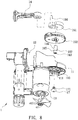
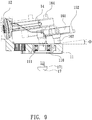
- a conventional air compressor 1 contains a base 11, a cylinder 12 connected on the base 11, a motor 13 and a piston 14 which are both connected on the base 11, wherein the piston 14 is driven by the motor 13 to move reciprocately in the cylinder 12 so as to draw, compress, pressurize, and discharge air.
- the motor 13 is actuated by a gear mechanism and a crank mechanism so as to drive the piston to move reciprocately.
- the gear mechanism includes a drive gear 151 mounted on a central shaft of the motor 13, and the gear mechanism includes a driven gear 152 meshing with the drive gear 151.
- the crank mechanism includes a counterweight portion 161 connected on the driven gear 152, a connection rod 164 rotatably connected with the piston 14, and a post 162 extending from the counterweight portion 161, wherein the post 162 has a small-diameter segment and a large-diameter segment, and the crank mechanism further includes a stepped portion 165 defined between the small-diameter segment and the large-diameter segment of the post 162, a cutout 166 defined on the large-diameter segment of the post 162 which is arranged on the counterweight portion 161, and a threaded orifice 163 formed on the small-diameter segment of the post 162 which is accommodated in a receiving orifice 110 of the base 11, and the receiving orifice 110 also accommodates a bearing 111.
- the post 162 of the crank mechanism is locked in the bearing 111 by using a screw element 17, wherein the connection rod 164 is eccentric relative to the post 162.
- the driven gear 152 is driven by the drive gear 151, the piston 14 is actuated to move in the cylinder 12 reciprocately.
- an angle ⁇ is defined among the piston 14, the driven gear 152, the crank mechanism, and a top 112 of the base 11 so that the post 162 does not contact with the base 11, the piston 14 is pushed into the cylinder 12, the post 162 is guided into the bearing 111, and the post 162 is locked in the bearing 111 by ways of the screw element 17.
- the base 11 covers the bearing 111, i.e., the top 112 of the base 11 does not flush with an outer face 113 of the bearing 111 in the base 11, wherein a spacing between the top 112 of the base 11 and the outer face 113 of the bearing 111 is a first distance D, a thickness of the base 11 is a second distance E, and a spacing between the top 113 of the base 11 and the driven gear 152 is a third distance B.
- a spacing between the piston 14 and the top 112 is a fourth distance F
- a spacing between the piston 14 and the outer face 113 of the bearing 111 is the fourth distance F + the first distance D.
- the base 11 covers the bearing 111, and the spacing between the top 112 of the base 11 and the outer face 113 of the bearing 111 is the first distance D, so the thickness (i.e., the second distance E) of the base 11 cannot be reduced.
- the present invention has arisen to mitigate and/or obviate the afore-described disadvantages.
- the primary aspect of the present invention is to provide a transmission mechanism of an air compressor in which the piston is rotatably connected with the connection rod of the torque gear, the piston is accommodated into the central orifice of the torque gear and corresponds to the internal ring of the bearing in the second positioning orifice of the base, and the screw bolt is screwed with the central orifice after being inserted through the internal ring of the bearing and the torque gear, such that when the air compressor operates, the torque gear engages with the bearing by using the screw bolt so that the bearing is not removed from the screw bolt, and the piston moves in the cylinder reciprocately.
- Another aspect of the present invention is to provide a transmission mechanism of an air compressor in which a spacing between the upper surface of the base and the toothed portion of the torque gear is a distance, wherein the distance is more than zero, such that the toothed portion does not friction with the upper surface of the base, when the torque gear rotates.
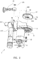
- an air compressor 2 according to a first embodiment of the present invention comprises: a base 3, a cylinder 4 connected on the base 3, a motor 5 and a transmission mechanism which are both connected on the base 3.
- the base 3 includes a first positioning orifice 31 and a second positioning orifice 32 separated from the first positioning orifice 31, a drive gear 50 inserted through the first positioning orifice 31 and mounted on a center of an end of the motor 5, and a bearing 6 accommodated in the second positioning orifice 32, wherein the bearing 6 is comprised of an external ring 61, an internal ring 62, and multiple balls 63 defined between the internal ring 62 and the external ring 61.
- the cylinder 4 is one-piece formed or is connected on the base 3, and the cylinder 4 includes an air storage seat 41 communicating thereon, wherein the air storage seat 41 has a delivery tube 411 configured to deliver air, and the air storage seat 41 has a pressure gauge 412.
- the transmission mechanism drives a piston 54 to reciprocately move in the cylinder 4, thus compressing the air.
- the transmission mechanism includes a torque gear 57 and a central orifice 510 defined on the torque gear 57, wherein the central orifice 510 has screw threads formed therein, and the transmission mechanism further includes a connection rod 53 extending from the torque gear 57, wherein the connection rod 53 has a notch 530 defined around a distal end of the connection rod 53.
- the piston 54 is rotatably connected with the connection rod 53 of the torque gear 57, the piston 54 is accommodated into the central orifice 510 of the torque gear 57 and corresponding to the internal ring 62 of the bearing 6 in the second positioning orifice 32 of the base 3, and a screw bolt 52 is screwed with the central orifice 510 after being inserted through the internal ring 62 of the bearing 6 and the torque gear 57, thus connecting the transmission mechanism automatedly.
- a locking ring 531 is retained in the notch 530 of the connection rod 53 so as to avoid a removal of the piston 54 from the torque gear 57.
- the torque gear 57 further has a counterweight portion and a toothed portion 51, wherein the counterweight portion and the toothed portion 51 are one-piece formed in a powder metallurgy manner or are connected together, and the toothed portion 51 meshes with the drive dear 50.
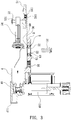
- an upper surface 30 of the base 3 flushes with a top 60 of the bearing 6, a thickness of the base 3 is a first distance A, a spacing between the upper surface 30 of the base 3 and the toothed portion 51 of the torque gear 57 is a second distance B, wherein the second distance B is more than zero, a spacing between the piston 54 and the top 60 of the bearing 6 is a third distance C. Since the second distance B is more than zero, the toothed portion 51 does not friction with the upper surface 30 of the base 3 when the torque gear 57 rotates.
- the central orifice 510 of the torque gear 57 is defined in the toothed portion 51 so that the second distance B is more than zero.
- the toothed portion 51 has a surrounding element 511 extending around a peripheral side of the central orifice 510 and one-pieces formed with the toothed portion 51.
- the surrounding element 511 is removably connected on a bottom of the torque gear 57, and the screw bot 52 is screwed with the central orifice 510 after being inserted through the internal ring 62 of the bearing 6, the surrounding element 511, and the torque gear 57.
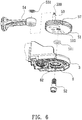
- the central orifice 560 of the torque gear 57 is defined on a counterweight portion 56 which is connected on a toothed portion 55, wherein the counterweight portion 56 has a surrounding element 561 extending around the peripheral side of the central orifice 560 and on a bottom of the counterweight portion 56, and the surrounding element 561 is one-piece formed with the counterweight portion 56.
- the torque gear 57 engages with the bearing 6 by using the screw bolt 52 so that the bearing 6 is not removed from the screw bolt 52, and the piston 54 moves in the cylinder 4 reciprocately.
- the piston 54 is rotatably connected with the connection rod 53 of the torque gear 57, the piston 54 is accommodated into the central orifice 510 of the torque gear 57 and corresponds to the internal ring 62 of the bearing 6 in the second positioning orifice 32 of the base 3, and the screw bolt 52 is screwed with the central orifice 510 after being inserted through the internal ring 62 of the bearing 6 and the torque gear 57.
- the torque gear 57 engages with the bearing 6 by using the screw bolt 52 so that the bearing 6 is not removed from the screw bolt 52, and the piston 54 moves in the cylinder 4 reciprocately.
Landscapes
- Engineering & Computer Science (AREA)
- General Engineering & Computer Science (AREA)
- Mechanical Engineering (AREA)
- Compressors, Vaccum Pumps And Other Relevant Systems (AREA)
- Compressor (AREA)
- Transmission Devices (AREA)
Claims (9)
- Mécanisme de transmission d'un compresseur d'air (2), le compresseur d'air (2) comprenant:une base (3) incluant un premier orifice de positionnement (31) et un second orifice de positionnement (32) séparé du premier orifice de positionnement (31), un engrenage d'entraînement (50) inséré à travers le premier orifice de positionnement (31) et monté sur un centre d'une extrémité d'un moteur (13), et un roulement (6) logé dans le second orifice de positionnement (32), dans lequel le roulement (6) est constitué d'un anneau externe (61), un anneau interne (62) et de multiples billes (63) définies entre l'anneau interne (62) et l'anneau externe (61); un cylindre (4) relié à la base (3) et incluant un siège de stockage d'air communiquant sur le cylindre (4); etle mécanisme de transmission entraînant un piston (54) à se déplacer en va-et-vient dans le cylindre (4), en comprimant ainsi l'air;dans lequel le mécanisme de transmission incluant un engrenage de couple (57) et un orifice central (510) défini sur l'engrenage de couple (57), dans lequel l'orifice central (510) présente des filetages de vis formés à l'intérieur de celui-ci, et le mécanisme de transmission inclut en outre une bielle (53) s'étendant depuis l'engrenage de couple (57), dans lequel l'orifice central (510) de l'engrenage de couple (57) correspond à l'anneau interne (62) du roulement (6) dans le second orifice de positionnement (32) de la base (3), et un boulon fileté (52) est vissé dans l'orifice central (510) après avoir été inséré à travers l'anneau interne (62) du roulement (6) et l'engrenage de couple (57), en reliant de ce fait automatiquement le mécanisme de transmission.
- Mécanisme de transmission selon la revendication 1, dans lequel l'engrenage de couple (57) présente en outre une portion de contrepoids et une portion dentée (51), et la portion dentée (51) s'engrène avec l'engrenage d'entraînement (50).
- Mécanisme de transmission selon la revendication 2, dans lequel la portion de contrepoids et la portion dentée (51) sont une pièce unique formée par métallurgie des poudres.
- Mécanisme de transmission selon la revendication 2, dans lequel une surface supérieure de la base (3) est arasée avec un sommet du roulement (6), un espacement entre la surface supérieure de la base (3) et la portion dentée (51) de l'engrenage de couple (57) est une distance qui est supérieure à zéro, de sorte que la portion dentée (51) ne frotte pas contre la surface supérieure de la base (3) lorsque l'engrenage de couple (57) tourne.
- Mécanisme de transmission selon la revendication 2, dans lequel l'orifice central (510) de l'engrenage de couple (57) est défini dans la portion dentée (51), et la portion dentée (51) présente un élément enveloppant (511) s'étendant autour d'un côté périphérique de l'orifice central (510) et des pièces uniques formées avec la portion dentée (51).
- Mécanisme de transmission selon la revendication 2, dans lequel un élément enveloppant (511) est relié, de manière amovible, à un fond de l'engrenage de couple (57), et le boulon fileté (52) est vissé dans l'orifice central (510) après avoir été inséré à travers l'anneau interne (62) du roulement (6), l'élément enveloppant (511), et l'engrenage de couple (57).
- Mécanisme de transmission selon la revendication 2, dans lequel l'orifice central (510) de l'engrenage de couple (57) est défini sur une portion de contrepoids qui est reliée à une portion dentée (51), dans lequel la portion de contrepoids présente un élément enveloppant (561) s'étendant autour du côté périphérique de l'orifice central (510) et sur un fond de la portion de contrepoids, et l'élément enveloppant (561) est une pièce unique formée avec la portion de contrepoids.
- Mécanisme de transmission selon la revendication 1, dans lequel, après que le piston (54) est relié en tournant à la bielle (53) de l'engrenage de couple (57), un anneau de verrouillage (531) est retenu dans une encoche (530) de la bielle (53) de manière à éviter un retrait du piston (54) de l'engrenage de couple (57).
- Mécanisme de transmission selon la revendication 1, dans lequel le piston (54) est relié en tournant à la bielle (53) de l'engrenage de couple (57), le piston (54) est logé dans l'orifice central (510) de l'engrenage de couple (57) et correspond à l'anneau interne (62) du roulement (6) dans le second orifice de positionnement (32) de la base (3), et le boulon fileté (52) est vissé dans l'orifice central (510) après avoir été inséré à travers l'anneau interne (62) du roulement (6) et l'engrenage de couple (57).
Priority Applications (1)
| Application Number | Priority Date | Filing Date | Title |
|---|---|---|---|
| PL19199681T PL3628869T3 (pl) | 2018-09-28 | 2019-09-25 | Mechanizm przekładni sprężarki powietrza |
Applications Claiming Priority (1)
| Application Number | Priority Date | Filing Date | Title |
|---|---|---|---|
| TW107134569A TWI684708B (zh) | 2018-09-28 | 2018-09-28 | 空氣壓縮機之傳動機構 |
Publications (2)
| Publication Number | Publication Date |
|---|---|
| EP3628869A1 EP3628869A1 (fr) | 2020-04-01 |
| EP3628869B1 true EP3628869B1 (fr) | 2021-10-27 |
Family
ID=68069611
Family Applications (1)
| Application Number | Title | Priority Date | Filing Date |
|---|---|---|---|
| EP19199681.8A Active EP3628869B1 (fr) | 2018-09-28 | 2019-09-25 | Mécanisme de transmission de compresseur d'air |
Country Status (10)
| Country | Link |
|---|---|
| US (1) | US10927827B2 (fr) |
| EP (1) | EP3628869B1 (fr) |
| JP (2) | JP6868071B2 (fr) |
| KR (1) | KR102182332B1 (fr) |
| CN (2) | CN110966156B (fr) |
| DE (1) | DE202019105326U1 (fr) |
| DK (1) | DK3628869T3 (fr) |
| HU (1) | HUE057689T2 (fr) |
| PL (1) | PL3628869T3 (fr) |
| TW (1) | TWI684708B (fr) |
Families Citing this family (2)
| Publication number | Priority date | Publication date | Assignee | Title |
|---|---|---|---|---|
| TWI676509B (zh) * | 2017-11-30 | 2019-11-11 | 已久工業股份有限公司 | 車載用空氣壓縮機之軸承的定位方法及其定位構造 |
| TWI684708B (zh) * | 2018-09-28 | 2020-02-11 | 已久工業股份有限公司 | 空氣壓縮機之傳動機構 |
Family Cites Families (24)
| Publication number | Priority date | Publication date | Assignee | Title |
|---|---|---|---|---|
| GB626845A (en) * | 1944-06-29 | 1949-07-22 | Smith & Sons Ltd S | Improvements in or relating to lubricating systems for air or gas compressors or pumps |
| US4551074A (en) * | 1981-10-01 | 1985-11-05 | Honda Giken Kogyo Kabushiki Kaisha | Air pump apparatus |
| US6095758A (en) * | 1998-03-30 | 2000-08-01 | Chou; Wen-San | Structure for a compact air compressor |
| US20020178907A1 (en) * | 2001-05-31 | 2002-12-05 | Wen San Chou | Air compressor having a smooth and stable structure |
| US20040105766A1 (en) * | 2002-01-25 | 2004-06-03 | Chou Wen San | Air compressor having stable configuration |
| KR200387141Y1 (ko) * | 2005-01-27 | 2005-06-17 | 웬-산 초우 | 안정된 구성을 가지는 공기 압축기 |
| DE102005029523A1 (de) * | 2005-06-25 | 2007-01-04 | Continental Aktiengesellschaft | Kompressor für ein Reifenpannenset |
| TW200831786A (en) * | 2007-01-30 | 2008-08-01 | Wen-Shan Chou | Air compressor structure |
| TWI531721B (zh) * | 2011-01-25 | 2016-05-01 | 周文三 | 空氣壓縮機 |
| TWI502132B (zh) * | 2011-07-08 | 2015-10-01 | Wen San Chou | Air compressor |
| US20140037425A1 (en) * | 2011-09-13 | 2014-02-06 | Black & Decker Inc. | Air ducting shroud for cooling an air compressor pump and motor |
| US20140020554A1 (en) * | 2012-07-19 | 2014-01-23 | Wei-Chi Wang | Air Pump Cylinder |
| CN202900578U (zh) * | 2012-10-31 | 2013-04-24 | 东莞瑞柯电子科技股份有限公司 | 一种气罐式空压机的机芯组件 |
| CN203430731U (zh) * | 2013-07-22 | 2014-02-12 | 大大电子实业(深圳)有限公司 | 电动打气机及其打气驱动装置 |
| TW201507901A (zh) * | 2013-08-27 | 2015-03-01 | Active Tools Int Hk Ltd | 輪胎修補機之空壓機的飛輪裝置 |
| TWI545258B (zh) * | 2014-04-07 | 2016-08-11 | 周文三 | 空氣壓縮機 |
| TWM496062U (zh) * | 2014-04-22 | 2015-02-21 | Wen-San Jhou | 減重型空氣壓縮機 |
| CN105089976B (zh) * | 2014-05-06 | 2018-01-30 | 周文三 | 减重型空气压缩机 |
| TWI591257B (zh) * | 2014-05-15 | 2017-07-11 | 周文三 | 空氣壓縮機之旋轉機構 |
| TWI579460B (zh) * | 2014-10-08 | 2017-04-21 | Wen-San Jhou | 空氣壓縮機之結合構造改良 |
| TWI580867B (zh) * | 2015-03-03 | 2017-05-01 | 周文三 | 空氣壓縮機之構造改良 |
| CN205001144U (zh) * | 2015-09-24 | 2016-01-27 | 张有进 | 空压机机芯 |
| CN108468789A (zh) * | 2018-06-04 | 2018-08-31 | 广西玉柴机器股份有限公司 | 新型空压机齿轮组件 |
| TWI684708B (zh) * | 2018-09-28 | 2020-02-11 | 已久工業股份有限公司 | 空氣壓縮機之傳動機構 |
-
2018
- 2018-09-28 TW TW107134569A patent/TWI684708B/zh active
-
2019
- 2019-08-29 KR KR1020190106350A patent/KR102182332B1/ko active IP Right Grant
- 2019-09-23 US US16/579,090 patent/US10927827B2/en active Active
- 2019-09-25 EP EP19199681.8A patent/EP3628869B1/fr active Active
- 2019-09-25 PL PL19199681T patent/PL3628869T3/pl unknown
- 2019-09-25 DK DK19199681.8T patent/DK3628869T3/da active
- 2019-09-25 CN CN201910911353.XA patent/CN110966156B/zh active Active
- 2019-09-25 HU HUE19199681A patent/HUE057689T2/hu unknown
- 2019-09-25 CN CN201921605112.4U patent/CN211082178U/zh not_active Withdrawn - After Issue
- 2019-09-25 DE DE202019105326.7U patent/DE202019105326U1/de not_active Expired - Lifetime
- 2019-09-27 JP JP2019177386A patent/JP6868071B2/ja active Active
- 2019-09-27 JP JP2019003672U patent/JP3227271U/ja active Active
Also Published As
| Publication number | Publication date |
|---|---|
| CN110966156B (zh) | 2022-01-11 |
| JP6868071B2 (ja) | 2021-05-12 |
| CN211082178U (zh) | 2020-07-24 |
| US20200102944A1 (en) | 2020-04-02 |
| EP3628869A1 (fr) | 2020-04-01 |
| JP3227271U (ja) | 2020-08-13 |
| DK3628869T3 (da) | 2022-01-31 |
| PL3628869T3 (pl) | 2022-02-21 |
| TWI684708B (zh) | 2020-02-11 |
| HUE057689T2 (hu) | 2022-06-28 |
| TW202012786A (zh) | 2020-04-01 |
| JP2020056406A (ja) | 2020-04-09 |
| KR20200037076A (ko) | 2020-04-08 |
| DE202019105326U1 (de) | 2019-10-04 |
| KR102182332B1 (ko) | 2020-11-25 |
| US10927827B2 (en) | 2021-02-23 |
| CN110966156A (zh) | 2020-04-07 |
Similar Documents
| Publication | Publication Date | Title |
|---|---|---|
| EP3628865B1 (fr) | Compresseur à air | |
| EP3608540B1 (fr) | Structure de fixation de palier de compresseur d'air | |
| EP3628869B1 (fr) | Mécanisme de transmission de compresseur d'air | |
| EP3667084B1 (fr) | Structure connexion pour moteur de compresseur d'air | |
| TWI660123B (zh) | Diaphragm pump | |
| US11454283B2 (en) | Method of mounting a bearing to an air compressor, and air compressor having a bearing mounted by the method | |
| JP5060587B2 (ja) | エアレススプレーポンプ | |
| US20210190054A1 (en) | Pump | |
| WO2019196389A1 (fr) | Pompe à cylindrée variable | |
| US6695604B1 (en) | Automotive fuel pump gear assembly having lifting and lubricating features | |
| TWM585303U (zh) | 空氣壓縮機之傳動機構 |
Legal Events
| Date | Code | Title | Description |
|---|---|---|---|
| PUAI | Public reference made under article 153(3) epc to a published international application that has entered the european phase |
Free format text: ORIGINAL CODE: 0009012 |
|
| STAA | Information on the status of an ep patent application or granted ep patent |
Free format text: STATUS: REQUEST FOR EXAMINATION WAS MADE |
|
| 17P | Request for examination filed |
Effective date: 20200127 |
|
| AK | Designated contracting states |
Kind code of ref document: A1 Designated state(s): AL AT BE BG CH CY CZ DE DK EE ES FI FR GB GR HR HU IE IS IT LI LT LU LV MC MK MT NL NO PL PT RO RS SE SI SK SM TR |
|
| AX | Request for extension of the european patent |
Extension state: BA ME |
|
| RIC1 | Information provided on ipc code assigned before grant |
Ipc: F04B 35/01 20060101ALI20210303BHEP Ipc: F04B 39/12 20060101ALI20210303BHEP Ipc: F04B 39/00 20060101ALI20210303BHEP Ipc: F04B 39/14 20060101AFI20210303BHEP Ipc: F04B 35/04 20060101ALI20210303BHEP Ipc: F04B 39/06 20060101ALI20210303BHEP Ipc: F04B 41/02 20060101ALI20210303BHEP |
|
| GRAP | Despatch of communication of intention to grant a patent |
Free format text: ORIGINAL CODE: EPIDOSNIGR1 |
|
| STAA | Information on the status of an ep patent application or granted ep patent |
Free format text: STATUS: GRANT OF PATENT IS INTENDED |
|
| INTG | Intention to grant announced |
Effective date: 20210414 |
|
| GRAS | Grant fee paid |
Free format text: ORIGINAL CODE: EPIDOSNIGR3 |
|
| GRAA | (expected) grant |
Free format text: ORIGINAL CODE: 0009210 |
|
| STAA | Information on the status of an ep patent application or granted ep patent |
Free format text: STATUS: THE PATENT HAS BEEN GRANTED |
|
| AK | Designated contracting states |
Kind code of ref document: B1 Designated state(s): AL AT BE BG CH CY CZ DE DK EE ES FI FR GB GR HR HU IE IS IT LI LT LU LV MC MK MT NL NO PL PT RO RS SE SI SK SM TR |
|
| REG | Reference to a national code |
Ref country code: GB Ref legal event code: FG4D |
|
| REG | Reference to a national code |
Ref country code: CH Ref legal event code: EP |
|
| REG | Reference to a national code |
Ref country code: AT Ref legal event code: REF Ref document number: 1442028 Country of ref document: AT Kind code of ref document: T Effective date: 20211115 |
|
| REG | Reference to a national code |
Ref country code: DE Ref legal event code: R096 Ref document number: 602019008682 Country of ref document: DE |
|
| REG | Reference to a national code |
Ref country code: IE Ref legal event code: FG4D |
|
| REG | Reference to a national code |
Ref country code: DK Ref legal event code: T3 Effective date: 20220126 |
|
| REG | Reference to a national code |
Ref country code: NL Ref legal event code: FP |
|
| REG | Reference to a national code |
Ref country code: SE Ref legal event code: TRGR |
|
| REG | Reference to a national code |
Ref country code: LT Ref legal event code: MG9D |
|
| PG25 | Lapsed in a contracting state [announced via postgrant information from national office to epo] |
Ref country code: RS Free format text: LAPSE BECAUSE OF FAILURE TO SUBMIT A TRANSLATION OF THE DESCRIPTION OR TO PAY THE FEE WITHIN THE PRESCRIBED TIME-LIMIT Effective date: 20211027 Ref country code: LT Free format text: LAPSE BECAUSE OF FAILURE TO SUBMIT A TRANSLATION OF THE DESCRIPTION OR TO PAY THE FEE WITHIN THE PRESCRIBED TIME-LIMIT Effective date: 20211027 Ref country code: FI Free format text: LAPSE BECAUSE OF FAILURE TO SUBMIT A TRANSLATION OF THE DESCRIPTION OR TO PAY THE FEE WITHIN THE PRESCRIBED TIME-LIMIT Effective date: 20211027 Ref country code: BG Free format text: LAPSE BECAUSE OF FAILURE TO SUBMIT A TRANSLATION OF THE DESCRIPTION OR TO PAY THE FEE WITHIN THE PRESCRIBED TIME-LIMIT Effective date: 20220127 |
|
| PG25 | Lapsed in a contracting state [announced via postgrant information from national office to epo] |
Ref country code: IS Free format text: LAPSE BECAUSE OF FAILURE TO SUBMIT A TRANSLATION OF THE DESCRIPTION OR TO PAY THE FEE WITHIN THE PRESCRIBED TIME-LIMIT Effective date: 20220227 Ref country code: PT Free format text: LAPSE BECAUSE OF FAILURE TO SUBMIT A TRANSLATION OF THE DESCRIPTION OR TO PAY THE FEE WITHIN THE PRESCRIBED TIME-LIMIT Effective date: 20220228 Ref country code: NO Free format text: LAPSE BECAUSE OF FAILURE TO SUBMIT A TRANSLATION OF THE DESCRIPTION OR TO PAY THE FEE WITHIN THE PRESCRIBED TIME-LIMIT Effective date: 20220127 Ref country code: LV Free format text: LAPSE BECAUSE OF FAILURE TO SUBMIT A TRANSLATION OF THE DESCRIPTION OR TO PAY THE FEE WITHIN THE PRESCRIBED TIME-LIMIT Effective date: 20211027 Ref country code: HR Free format text: LAPSE BECAUSE OF FAILURE TO SUBMIT A TRANSLATION OF THE DESCRIPTION OR TO PAY THE FEE WITHIN THE PRESCRIBED TIME-LIMIT Effective date: 20211027 Ref country code: GR Free format text: LAPSE BECAUSE OF FAILURE TO SUBMIT A TRANSLATION OF THE DESCRIPTION OR TO PAY THE FEE WITHIN THE PRESCRIBED TIME-LIMIT Effective date: 20220128 Ref country code: ES Free format text: LAPSE BECAUSE OF FAILURE TO SUBMIT A TRANSLATION OF THE DESCRIPTION OR TO PAY THE FEE WITHIN THE PRESCRIBED TIME-LIMIT Effective date: 20211027 |
|
| REG | Reference to a national code |
Ref country code: HU Ref legal event code: AG4A Ref document number: E057689 Country of ref document: HU |
|
| REG | Reference to a national code |
Ref country code: DE Ref legal event code: R097 Ref document number: 602019008682 Country of ref document: DE |
|
| PG25 | Lapsed in a contracting state [announced via postgrant information from national office to epo] |
Ref country code: SM Free format text: LAPSE BECAUSE OF FAILURE TO SUBMIT A TRANSLATION OF THE DESCRIPTION OR TO PAY THE FEE WITHIN THE PRESCRIBED TIME-LIMIT Effective date: 20211027 Ref country code: SK Free format text: LAPSE BECAUSE OF FAILURE TO SUBMIT A TRANSLATION OF THE DESCRIPTION OR TO PAY THE FEE WITHIN THE PRESCRIBED TIME-LIMIT Effective date: 20211027 Ref country code: RO Free format text: LAPSE BECAUSE OF FAILURE TO SUBMIT A TRANSLATION OF THE DESCRIPTION OR TO PAY THE FEE WITHIN THE PRESCRIBED TIME-LIMIT Effective date: 20211027 Ref country code: EE Free format text: LAPSE BECAUSE OF FAILURE TO SUBMIT A TRANSLATION OF THE DESCRIPTION OR TO PAY THE FEE WITHIN THE PRESCRIBED TIME-LIMIT Effective date: 20211027 |
|
| PLBE | No opposition filed within time limit |
Free format text: ORIGINAL CODE: 0009261 |
|
| STAA | Information on the status of an ep patent application or granted ep patent |
Free format text: STATUS: NO OPPOSITION FILED WITHIN TIME LIMIT |
|
| 26N | No opposition filed |
Effective date: 20220728 |
|
| PG25 | Lapsed in a contracting state [announced via postgrant information from national office to epo] |
Ref country code: AL Free format text: LAPSE BECAUSE OF FAILURE TO SUBMIT A TRANSLATION OF THE DESCRIPTION OR TO PAY THE FEE WITHIN THE PRESCRIBED TIME-LIMIT Effective date: 20211027 |
|
| PG25 | Lapsed in a contracting state [announced via postgrant information from national office to epo] |
Ref country code: SI Free format text: LAPSE BECAUSE OF FAILURE TO SUBMIT A TRANSLATION OF THE DESCRIPTION OR TO PAY THE FEE WITHIN THE PRESCRIBED TIME-LIMIT Effective date: 20211027 |
|
| PGFP | Annual fee paid to national office [announced via postgrant information from national office to epo] |
Ref country code: IT Payment date: 20220930 Year of fee payment: 4 |
|
| PG25 | Lapsed in a contracting state [announced via postgrant information from national office to epo] |
Ref country code: MC Free format text: LAPSE BECAUSE OF FAILURE TO SUBMIT A TRANSLATION OF THE DESCRIPTION OR TO PAY THE FEE WITHIN THE PRESCRIBED TIME-LIMIT Effective date: 20211027 Ref country code: CZ Free format text: LAPSE BECAUSE OF NON-PAYMENT OF DUE FEES Effective date: 20220925 |
|
| REG | Reference to a national code |
Ref country code: CH Ref legal event code: PL |
|
| REG | Reference to a national code |
Ref country code: DK Ref legal event code: EBP Effective date: 20220930 |
|
| REG | Reference to a national code |
Ref country code: SE Ref legal event code: EUG |
|
| REG | Reference to a national code |
Ref country code: NL Ref legal event code: MM Effective date: 20221001 |
|
| REG | Reference to a national code |
Ref country code: BE Ref legal event code: MM Effective date: 20220930 |
|
| REG | Reference to a national code |
Ref country code: AT Ref legal event code: UEP Ref document number: 1442028 Country of ref document: AT Kind code of ref document: T Effective date: 20211027 |
|
| P01 | Opt-out of the competence of the unified patent court (upc) registered |
Effective date: 20230523 |
|
| PG25 | Lapsed in a contracting state [announced via postgrant information from national office to epo] |
Ref country code: NL Free format text: LAPSE BECAUSE OF NON-PAYMENT OF DUE FEES Effective date: 20221001 Ref country code: LU Free format text: LAPSE BECAUSE OF NON-PAYMENT OF DUE FEES Effective date: 20220925 |
|
| PG25 | Lapsed in a contracting state [announced via postgrant information from national office to epo] |
Ref country code: LI Free format text: LAPSE BECAUSE OF NON-PAYMENT OF DUE FEES Effective date: 20220930 Ref country code: IE Free format text: LAPSE BECAUSE OF NON-PAYMENT OF DUE FEES Effective date: 20220925 Ref country code: HU Free format text: LAPSE BECAUSE OF NON-PAYMENT OF DUE FEES Effective date: 20220926 Ref country code: FR Free format text: LAPSE BECAUSE OF NON-PAYMENT OF DUE FEES Effective date: 20220930 Ref country code: CH Free format text: LAPSE BECAUSE OF NON-PAYMENT OF DUE FEES Effective date: 20220930 |
|
| PG25 | Lapsed in a contracting state [announced via postgrant information from national office to epo] |
Ref country code: SE Free format text: LAPSE BECAUSE OF NON-PAYMENT OF DUE FEES Effective date: 20220926 |
|
| PG25 | Lapsed in a contracting state [announced via postgrant information from national office to epo] |
Ref country code: BE Free format text: LAPSE BECAUSE OF NON-PAYMENT OF DUE FEES Effective date: 20220930 |
|
| PG25 | Lapsed in a contracting state [announced via postgrant information from national office to epo] |
Ref country code: DK Free format text: LAPSE BECAUSE OF NON-PAYMENT OF DUE FEES Effective date: 20220930 |
|
| PGFP | Annual fee paid to national office [announced via postgrant information from national office to epo] |
Ref country code: DE Payment date: 20230920 Year of fee payment: 5 |
|
| PG25 | Lapsed in a contracting state [announced via postgrant information from national office to epo] |
Ref country code: CY Free format text: LAPSE BECAUSE OF FAILURE TO SUBMIT A TRANSLATION OF THE DESCRIPTION OR TO PAY THE FEE WITHIN THE PRESCRIBED TIME-LIMIT Effective date: 20211027 |
|
| GBPC | Gb: european patent ceased through non-payment of renewal fee |
Effective date: 20230925 |
|
| PG25 | Lapsed in a contracting state [announced via postgrant information from national office to epo] |
Ref country code: PL Free format text: LAPSE BECAUSE OF NON-PAYMENT OF DUE FEES Effective date: 20220925 Ref country code: MK Free format text: LAPSE BECAUSE OF FAILURE TO SUBMIT A TRANSLATION OF THE DESCRIPTION OR TO PAY THE FEE WITHIN THE PRESCRIBED TIME-LIMIT Effective date: 20211027 |
|
| PG25 | Lapsed in a contracting state [announced via postgrant information from national office to epo] |
Ref country code: GB Free format text: LAPSE BECAUSE OF NON-PAYMENT OF DUE FEES Effective date: 20230925 |
|
| PG25 | Lapsed in a contracting state [announced via postgrant information from national office to epo] |
Ref country code: GB Free format text: LAPSE BECAUSE OF NON-PAYMENT OF DUE FEES Effective date: 20230925 |