EP3628852A1 - Ventil und verfahren zum herstellen eines ventils - Google Patents
Ventil und verfahren zum herstellen eines ventils Download PDFInfo
- Publication number
- EP3628852A1 EP3628852A1 EP18465579.3A EP18465579A EP3628852A1 EP 3628852 A1 EP3628852 A1 EP 3628852A1 EP 18465579 A EP18465579 A EP 18465579A EP 3628852 A1 EP3628852 A1 EP 3628852A1
- Authority
- EP
- European Patent Office
- Prior art keywords
- valve seat
- valve
- opening
- seat sleeve
- housing body
- Prior art date
- Legal status (The legal status is an assumption and is not a legal conclusion. Google has not performed a legal analysis and makes no representation as to the accuracy of the status listed.)
- Granted
Links
Images


Classifications
-
- F—MECHANICAL ENGINEERING; LIGHTING; HEATING; WEAPONS; BLASTING
- F02—COMBUSTION ENGINES; HOT-GAS OR COMBUSTION-PRODUCT ENGINE PLANTS
- F02D—CONTROLLING COMBUSTION ENGINES
- F02D9/00—Controlling engines by throttling air or fuel-and-air induction conduits or exhaust conduits
- F02D9/04—Controlling engines by throttling air or fuel-and-air induction conduits or exhaust conduits concerning exhaust conduits
-
- F—MECHANICAL ENGINEERING; LIGHTING; HEATING; WEAPONS; BLASTING
- F02—COMBUSTION ENGINES; HOT-GAS OR COMBUSTION-PRODUCT ENGINE PLANTS
- F02M—SUPPLYING COMBUSTION ENGINES IN GENERAL WITH COMBUSTIBLE MIXTURES OR CONSTITUENTS THEREOF
- F02M26/00—Engine-pertinent apparatus for adding exhaust gases to combustion-air, main fuel or fuel-air mixture, e.g. by exhaust gas recirculation [EGR] systems
- F02M26/65—Constructional details of EGR valves
- F02M26/66—Lift valves, e.g. poppet valves
-
- F—MECHANICAL ENGINEERING; LIGHTING; HEATING; WEAPONS; BLASTING
- F02—COMBUSTION ENGINES; HOT-GAS OR COMBUSTION-PRODUCT ENGINE PLANTS
- F02M—SUPPLYING COMBUSTION ENGINES IN GENERAL WITH COMBUSTIBLE MIXTURES OR CONSTITUENTS THEREOF
- F02M26/00—Engine-pertinent apparatus for adding exhaust gases to combustion-air, main fuel or fuel-air mixture, e.g. by exhaust gas recirculation [EGR] systems
- F02M26/65—Constructional details of EGR valves
- F02M26/66—Lift valves, e.g. poppet valves
- F02M26/69—Lift valves, e.g. poppet valves having two or more valve-closing members
-
- F—MECHANICAL ENGINEERING; LIGHTING; HEATING; WEAPONS; BLASTING
- F16—ENGINEERING ELEMENTS AND UNITS; GENERAL MEASURES FOR PRODUCING AND MAINTAINING EFFECTIVE FUNCTIONING OF MACHINES OR INSTALLATIONS; THERMAL INSULATION IN GENERAL
- F16K—VALVES; TAPS; COCKS; ACTUATING-FLOATS; DEVICES FOR VENTING OR AERATING
- F16K11/00—Multiple-way valves, e.g. mixing valves; Pipe fittings incorporating such valves
- F16K11/02—Multiple-way valves, e.g. mixing valves; Pipe fittings incorporating such valves with all movable sealing faces moving as one unit
- F16K11/04—Multiple-way valves, e.g. mixing valves; Pipe fittings incorporating such valves with all movable sealing faces moving as one unit comprising only lift valves
-
- F—MECHANICAL ENGINEERING; LIGHTING; HEATING; WEAPONS; BLASTING
- F16—ENGINEERING ELEMENTS AND UNITS; GENERAL MEASURES FOR PRODUCING AND MAINTAINING EFFECTIVE FUNCTIONING OF MACHINES OR INSTALLATIONS; THERMAL INSULATION IN GENERAL
- F16K—VALVES; TAPS; COCKS; ACTUATING-FLOATS; DEVICES FOR VENTING OR AERATING
- F16K27/00—Construction of housing; Use of materials therefor
- F16K27/02—Construction of housing; Use of materials therefor of lift valves
- F16K27/0236—Diaphragm cut-off apparatus
Definitions
- a valve for opening and closing an exhaust pipe and a method for producing such a valve are specified.
- Valves for opening and closing an exhaust pipe are used in motor vehicles.
- the tightness with which the valve can close the line is important for the function of such valves. In the case of gases in particular, achieving a low leak rate is very time-consuming.
- the drive of a tappet of the valve is typically formed by an electric motor and a gear.
- the gear serves to convert the rotary movement of the electric motor into a translatory movement so that the tappet connected to the gear can be moved linearly.
- a sealing seat of the valve is produced, for example, from a solid body by means of a machining manufacturing process such as turning or milling.
- a valve for opening and closing an exhaust pipe of a motor vehicle has a housing body.
- the valve has a tappet arranged in the housing body.
- the tappet can be coupled to a drive at a first end.
- the plunger is designed to be moved along a longitudinal axis of the plunger.
- the valve has a valve seat sleeve.
- a valve seat is formed on the valve seat sleeve.
- the valve seat delimits an opening.
- the valve seat sleeve is arranged in the housing body.
- the valve seat sleeve is by means of a deep-drawing process produced.
- the valve has a closing body.
- the closing body is connected to the plunger, so that the closing body can be adjusted between an open position and a closed position by moving the plunger.
- the opening is released in the open position. In the closed position, the closing body lies against the valve seat and seals the opening.
- the valve has the valve seat sleeve, which is designed as a separate component to the rest of the housing body.
- the housing body has in particular several components of the valve and can be coupled, for example, to the drive.
- the valve seat sleeve is arranged within the housing body.
- the sealing seat is not formed directly on the housing body, but on the valve seat sleeve.
- the valve seat sleeve surrounds the opening, which can be closed by the closing body. In the closed position, the closing body is in contact with the valve seat sleeve and in particular is not in contact with the housing body.
- the valve seat sleeve which is produced by deep drawing, is cheaper and can be produced with less material than the elements on which the valve seats are conventionally arranged.
- valve seat is not cut out of a solid body.
- the conventional loss of material can thus be avoided.
- the valve seat sleeve is formed from a sheet metal. It is therefore possible to manufacture the housing body with larger tolerances.
- the valve seat sleeve with the valve seat can be easily manufactured with small tolerances. Sufficient tightness can thus be achieved during operation.
- valve seat sleeve is fixed in the housing body by means of an interference fit. Axial movement of the valve seat sleeve relative to the housing body is thus reliably blocked.
- the valve seat sleeve is axially fixed in the housing body by means of a hook.
- the valve seat sleeve is designed so that it can be pressed into the housing body for assembly. In the event of a displacement against the direction of assembly, at least some of the valve seat sleeve easily penetrates into the material of the housing body. A rear hooking is thus realized and an axial movement is blocked.
- the closing body is manufactured by means of a stamping process.
- the closing body is punched out of a metal sheet.
- the closing body is at least slightly resilient. This enables a sufficiently firm pressing onto the sealing seat in the closed position while relieving the pressure on the connection between the closing body and the plunger.
- the valve seat sleeve has a second valve seat.
- the second valve seat defines a second opening.
- the second opening has a smaller diameter than the opening.
- the valve has a second closing body.
- the second closing body is connected to the tappet, so that the second closing body can be adjusted by moving the tappet between the open position, in which the second opening is released, and the closed position. In the closed position, the second closing body seals the second opening and bears against the second valve seat.
- the second closing body has a smaller diameter than the closing body.
- the diameter of the closing body is matched to the diameter of the opening.
- the diameter of the second closing body is matched to the diameter of the second opening. Because the diameters of the second closing body and the second opening are smaller than the diameters of the opening and the closing body, simple assembly is possible and sufficient tightness is achieved during operation.
- the valve seat sleeve has at least one step along the longitudinal axis.
- the gradation serves as a stop for the valve seat sleeve on the housing body. Axial movement of the valve seat sleeve relative to the housing body is thus limited during operation and during assembly.
- a method for producing a valve comprises providing a metal sheet.
- the metal sheet is deep-drawn and the valve seat sleeve is thereby formed. It is thus reliably possible to produce the valve seat sleeve with the valve seat with little material expenditure.
- a further metal sheet is provided.
- the further metal sheet is punched and the closing body is thereby formed. It is therefore possible to produce a sufficiently stable closing body with a small amount of material.
- the further metal sheet is a comparatively thin metal sheet, so that a flexible closing body can be produced.
- the housing body is provided with an inner radius.
- the metal sheet is deep-drawn so that the valve seat sleeve is formed with an outer radius.
- the outside radius is larger than the inside radius.
- the valve seat sleeve is pressed into the housing body. A simple and reliable connection of the valve seat sleeve and the housing body is thus possible.
- valve described is particularly suitable for linear valves in which the tappet is moved linearly in one direction, in particular its longitudinal axis.
- the valve can also have a further valve seat with a further one Have valve opening (double linear valve), which can be closed or released at the same time as the first valve opening by the tappet movement by means of a corresponding closing body.
- the valve can thus be designed as a double linear valve or with only a single closing body as a single linear valve.
- the valve can be used in an exhaust gas recirculation system of a motor vehicle to open and close the exhaust pipe of the motor vehicle.
- an exhaust gas recirculation system of a motor vehicle has the valve.
- FIG. 1 shows a valve 100 according to an embodiment for opening and closing an exhaust pipe.
- the valve 100 in Figure 1 has a housing 1 in which an electric motor 2 is arranged. By means of a gear 3, the rotary movement of the electric motor 2 converted into a linear movement of a plunger 4.
- a sensor 5 is arranged on the transmission 3, which cooperates with a magnet attached to the tappet 4.
- the tappet 4 extends from the gear chamber 6 into a valve chamber 7, the tappet 4 being mounted at two points 8.
- the valve chamber 7 consists of three partial chambers 7a, 7b, 7c, which are located one behind the other and are each separated from one another by a valve seat 9.
- Two closing bodies 10 are arranged on the tappet 4 such that when the tappet 4 moves along a longitudinal axis 205 of the tappet 4 they rest against the respective valve seat 9 and seal an opening 11 or move it away from the valve seat 9 and thus open the opening 11, that a gas can flow from one valve chamber 7 into the other.
- valve 100 according to an exemplary embodiment of the invention is described below, which has a modified design of the valve seat 9. Incidentally, the valve 100 can display the features of FIG Figure 1 have the described configuration. However, it should be noted that in Figure 1 The valve 100 described is to be understood as an example and, alternatively, can also have other configurations, without there being any restrictions for the following description of the exemplary embodiment of the invention.
- Figure 2 shows a sectional view of the valve 100.
- the valve has a housing body 200.
- the housing body is formed, for example, from a metal and can have comparatively large manufacturing tolerances.
- the housing body 200 thus replaces the housing 1.
- the housing body 200 is present, for example, in addition to the housing 1 and is fastened to the housing 1.
- the tappet 4 is coupled to the drive 222 at a first end 201. Starting from the first end 201, the plunger 4 extends along the longitudinal axis 205 to a second end 202.
- the closing body 10 is connected to the plunger.
- a second closing body 218 is also connected to the plunger.
- the two closing bodies 10, 218 are arranged offset to one another along the longitudinal axis 205.
- the plunger 205 extends into the housing body 200 and in particular into an interior 212 of the housing body 200.
- the closing bodies 10, 218 are also arranged in the interior 212.
- a valve seat sleeve 203 is arranged in the interior 212 of the housing body 200.
- the valve seat sleeve 203 is at least in sections in contact with the inner walls of the housing body 200, which surround the interior 212.
- the valve seat sleeve 203 extends along the longitudinal axis 205.
- the outer shape of the valve seat sleeve 203 is matched to the shape of the interior 212, so that the valve seat sleeve can be stably supported in the housing body 200.
- the valve seat 9 for the closing body 10 is formed on the valve seat sleeve 203.
- a second valve seat 216 for the second closing body 218 is formed on the valve seat sleeve 3.
- the second valve seat 216 surrounds a second opening 217, which can be closed or released by means of the second closing body 218.
- the valve 100 has an inlet 213, which is arranged in particular between the closing body 10 and the second closing body 218.
- the valve 100 has, for example, two outlets 214, 215, which are each arranged on the side of the closing body 10 and the second closing body 218 facing away from the inlet 213.
- FIG. 3 shows a detailed representation of a portion of valve 100.
- valve sleeve 203 is pressed into the interior 212 of the housing body 200 by means of a press fit 204. As a result, the valve seat sleeve 203 is stably arranged in the housing body 200.
- the valve seat sleeve has two gradations 210, which correspond to corresponding gradations of the housing body 200. Thus, displacement of the valve seat sleeve 203 along a direction of the longitudinal axis 205 is blocked.
- a diameter 207 of the opening 11 is larger than a diameter 206 of the second opening 217.
- the gradation 210 can thus be implemented.
- a simple assembly of the plunger 4 with the two closing bodies 10, 218 is possible.
- the plunger 4 is introduced into the housing body 200 and the valve seat sleeve 203 along the longitudinal axis 205 starting with the smaller second closing body 218.
- the closing body 10 has a larger diameter 209 than the second closing body 218.
- a third diameter 208 of the second closing body 218 is smaller than the diameter 209 of the closing body 10.
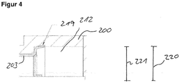
- Figure 4 shows a possibility of axially fixing the valve seat sleeve 203 in the housing body 200.
- the valve seat sleeve 203 has an oblique flank 211 at its end with the largest diameter.
- the inclined flank is designed in such a way that the valve seat sleeve 203 can be pushed into the housing body 200 along the first direction.
- the inclined flank 211 is at least slightly pressed into the wall of the housing body 200. This deforms slightly plastic, for example.
- a rear hook 219 is thereby formed.
- the gradation 210 blocks a movement of the valve seat sleeve 203 relative to the housing body 200 along the
- valve seat sleeve 203 is fixed in the housing body 200 by means of the press fit 204.
- An outer radius 221 of the valve seat sleeve 203 is made larger than a corresponding inner radius 220 of the housing body 200.
- valve seats 9 and 216 are not formed directly on the housing body 200, but on the valve seat sleeve 203.
- the valve seat sleeve is produced, for example, from a metal sheet by means of a deep-drawing process.
- the valve seat sleeve can thus be produced inexpensively and with sufficient precision while retaining material losses.
- the valve seat sleeve 203 only has to be reworked a little after the deep-drawing process, in order to be able to ensure sufficient tightness of the valve 100 during operation.
- the closing bodies 10 and 218 are each manufactured, for example, from a metal sheet by means of a stamping process.
- the metal sheet is in particular relatively thin, so that light and flexible closing bodies 10, 218 can be produced.
- the closing bodies 10, 218 are each fastened to the plunger 4, for example, by means of a weld. Because of the flexibility of the closing bodies 10, 218, the weld is stressed less, particularly in the closed position, when the closing bodies 10, 281 are pressed against their respective valve seats 9, 216.
- valve seat sleeve 203 Due to the at least sectionally conical shape of the valve seat sleeve 203 on the inclined flank 211, the valve seat sleeve 203 is axially self-locking relative to the housing body 200 trainable. As a result, according to exemplary embodiments, further connection means, such as welding between the housing body 200 and the valve seat sleeve 203, can be dispensed with.
- the closing bodies 10, 218 can be produced simply as round stamped parts or stamped parts by means of the stamping method or stamping method.
- the press fit 204 is formed only on the region of the valve seat sleeve 203 which has the largest diameter.
- the valve 100 has a compact and lightweight construction and ensures reliable operation. In addition, the valve 100 is simple and inexpensive to manufacture.
Landscapes
- Engineering & Computer Science (AREA)
- General Engineering & Computer Science (AREA)
- Mechanical Engineering (AREA)
- Chemical & Material Sciences (AREA)
- Combustion & Propulsion (AREA)
- Lift Valve (AREA)
Abstract
Description
- Es wird ein Ventil zum Öffnen und Schließen einer Abgasleitung angegeben sowie ein Verfahren zum Herstellen eines derartigen Ventils.
- In Kraftfahrzeugen werden Ventile zum Öffnen und Schließen einer Abgasleitung eingesetzt. Wichtig für die Funktion solcher Ventile ist die Dichtheit, mit der das Ventil die Leitung verschließen kann. Gerade bei Gasen ist das Erreichen einer geringen Leckrate mit hohem Aufwand verbunden. Der Antrieb eines Stößels des Ventils wird typischerweise von einem Elektromotor und einem Getriebe gebildet. Das Getriebe dient dazu, die Drehbewegung des Elektromotors in eine translatorische Bewegung umzuwandeln, damit der mit dem Getriebe verbundene Stößel linear bewegt werden kann. Ein Dichtsitz des Ventils ist beispielsweise mittels eines spanenden Fertigungsverfahrens wie Drehen oder Fräsen aus einem Vollkörper hergestellt.
- Es ist wünschenswert, ein Ventil anzugeben, das einfach und zuverlässig ist. Zudem ist es wünschenswert, ein Verfahren zum Herstellen eines Ventils anzugeben, das eine einfache Herstellung des Ventils ermöglicht und kostengünstig ist.
- Gemäß einer Ausführungsform weist ein Ventil zum Öffnen und Schließen einer Abgasleitung eines Kraftfahrzeugs einen Gehäusekörper auf. Das Ventil weist einen in dem Gehäusekörper angeordneten Stößel auf. Der Stößel ist an einem ersten Ende mit einem Antrieb koppelbar. Der Stößel ist ausgebildet, entlang einer Längsachse des Stößels bewegt zu werden. Das Ventil weist eine Ventilsitzhülse auf. An der Ventilsitzhülse ist ein Ventilsitz ausgebildet. Der Ventilsitz begrenzt eine Öffnung. Die Ventilsitzhülse ist in dem Gehäusekörper angeordnet. Die Ventilsitzhülse ist mittels eines Tiefziehverfahrens hergestellt. Das Ventil weist einen Schließkörper auf. Der Schließkörper ist mit dem Stößel verbunden, sodass der Schließkörper mittels einer Bewegung des Stößels zwischen einer Offenstellung und einer Schließstellung verstellbar ist. In der Offenstellung ist die Öffnung freigegeben. In der Schließstellung liegt der Schließkörper an dem Ventilsitz an und dichtet die Öffnung ab.
- Das Ventil weist die Ventilsitzhülse auf, die als separates Bauteil zum übrigen Gehäusekörper ausgebildet ist. Der Gehäusekörper weist insbesondere mehrere Bauteile des Ventils auf und ist beispielsweise mit dem Antrieb koppelbar. Innerhalb des Gehäusekörpers wird die Ventilsitzhülse angeordnet. Der Dichtsitz ist nicht am Gehäusekörper direkt ausgebildet, sondern an der Ventilsitzhülse. Die Ventilsitzhülse umgibt die Öffnung, die von dem Schließkörper verschlossen werden kann. In der Schließstellung ist der Schließkörper in Kontakt mit der Ventilsitzhülse und insbesondere nicht in Kontakt mit dem Gehäusekörper. Die Ventilsitzhülse, die mittels Tiefziehen hergestellt ist, ist günstiger und mit geringem Material aufwand herstellbar als die Elemente, an denen herkömmlich die Ventilsitze angeordnet sind. Insbesondere ist der Ventilsitz nicht aus einem Vollkörper ausgeschnitten. Der herkömmliche Materialverlust ist somit vermeidbar. Die Ventilsitzhülse ist aus einem Metallblech geformt. Somit ist es möglich, den Gehäusekörper mit größeren Toleranzen zu fertigen. Die Ventilsitzhülse mit dem Ventilsitz ist einfach mit geringen Toleranzen herstellbar. Somit ist eine ausreichende Dichtheit im Betrieb realisierbar.
- Gemäß einer Ausführungsform ist die Ventilsitzhülse mittels einer Presspassung in dem Gehäusekörper fixiert. Somit wird eine axiale Bewegung der Ventilsitzhülse relativ zum Gehäusekörper verlässlich blockiert.
- Gemäß einer Ausführungsform ist die Ventilsitzhülse mittels einer Hinterhakung in dem Gehäusekörper axial fixiert. Insbesondere ist die Ventilsitzhülse so ausgebildet, dass sie zur Montage in den Gehäusekörper eingepresst werden kann. Bei einer Verschiebung entgegen der Montagerichtung dringt die Ventilsitzhülse zumindest mit einem Teil leicht in das Material des Gehäusekörpers ein. Somit ist eine Hinterhakung realisiert und eine axiale Bewegung blockiert.
- Gemäß einer Ausführungsform ist der Schließkörper mittels eines Stanzverfahrens hergestellt. Beispielsweise ist der Schließkörper aus einem Metallblech ausgestanzt. Der Schließkörper ist so zumindest leicht federnd ausgebildet. Dies ermöglicht ein ausreichend festes Aufpressen auf den Dichtsitz in der Schließstellung bei gleichzeitiger Entlastung der Verbindung zwischen Schließkörper und Stößel.
- Gemäß einer Ausführungsform weist die Ventilsitzhülse einen zweiten Ventilsitz auf. Der zweite Ventilsitz begrenzt eine zweite Öffnung. Die zweite Öffnung weist einen kleineren Durchmesser auf als die Öffnung. Gemäß einer Ausführungsform weist das Ventil einen zweiten Schließkörper auf. Der zweite Schließkörper ist mit dem Stößel verbunden, so dass der zweite Schließkörper mittels einer Bewegung des Stößels zwischen der Offenstellung, in der die zweite Öffnung freigegeben ist, und der Schließstellung verstellbar ist. In der Schließstellung dichtet der zweite Schließkörper die zweite Öffnung ab und liegt an dem zweiten Ventilsitz an. Der zweite Schließkörper weist einen kleineren Durchmesser auf als der Schließkörper. Der Durchmesser des Schließkörpers ist auf den Durchmesser der Öffnung abgestimmt. Der Durchmesser des zweiten Schließkörpers ist auf den Durchmesser der zweiten Öffnung abgestimmt. Dadurch, dass die Durchmesser des zweiten Schließkörpers und der zweiten Öffnung kleiner sind als die Durchmesser der Öffnung und des Schließkörpers, ist eine einfache Montage möglich und eine ausreichende Dichtigkeit im Betrieb realisiert.
- Gemäß einer Ausführungsform weist die Ventilsitzhülse entlang der Längsachse mindestens eine Abstufung auf. Die Abstufung dient als Anschlag für die Ventilsitzhülse an dem Gehäusekörper. Somit ist im Betrieb und während der Montage eine axiale Bewegung der Ventilsitzhülse relativ zum Gehäusekörper begrenzt.
- Ein Verfahren zum Herstellen eines Ventils, insbesondere eines Ventils gemäß einer der beschriebenen Ausführungsformen, umfasst ein Bereitstellen eines Metallblechs. Das Metallblech wird tiefgezogen und dadurch wird die Ventilsitzhülse ausgebildet. Somit ist es mit geringem Materialaufwand zuverlässig möglich, die Ventilsitzhülse mit dem Ventilsitz herzustellen.
- Gemäß einer Ausführungsform wird ein weiteres Metallblech bereitgestellt. Das weitere Metallblech wird gestanzt und dadurch wird der Schließkörper ausgebildet. Somit ist es mit geringem Materialeinsatz möglich, einen ausreichend stabilen Schließkörper herzustellen. Beispielsweise ist das weitere Metallblech ein vergleichsweise dünnes Metallblech, sodass ein flexibler Schließkörper herstellbar ist.
- Gemäß einer Ausführungsform wird der Gehäusekörper mit einem Innenradius bereitgestellt. Das Metallblech wird tiefgezogen, sodass die Ventilsitzhülse mit einem Außenradius ausgebildet wird. Der Außenradius ist größer als der Innenradius. Die Ventilsitzhülse wird in den Gehäusekörper eingepresst. Somit ist eine einfache und zuverlässige Verbindung der Ventilsitzhülse und des Gehäusekörpers möglich.
- Insgesamt ist es möglich, ein kostengünstiges, kompaktes und leichtes Ventil anzugeben und herzustellen.
- Das beschriebene Ventil eignet sich insbesondere für Linearventile, bei denen der Stößel entlang einer Richtung, insbesondere seiner Längsachse, linear bewegt wird. Weiterhin kann das Ventil auch einen weiteren Ventilsitz mit einer weiteren Ventilöffnung aufweisen (Doppellinearventil), die gleichzeitig zur ersten Ventilöffnung durch die Stößelbewegung mittels eines entsprechenden Schließkörpers verschlossen oder freigegeben werden kann. Das Ventil kann also als Doppellinearventil ausgebildet sein oder mit nur einem einzigen Schließkörper als Einfachlinearventil.
- Beispielsweise ist das Ventil in einem Abgasrückführsystem eines Kraftfahrzeugs einsetzbar, um die Abgasleitung des Kraftfahrzeugs zu öffnen und zu schließen. Beispielsweise weist ein Abgasrückführsystem eines Kraftfahrzeugs das Ventil auf.
- Weitere Vorteile, Merkmale und Weiterbildungen ergeben sich aus den nachfolgenden, in Verbindung mit den Figuren erläuterten Ausführungsbeispielen. Gleiche, gleichartige oder gleich wirkende Elemente können figurenübergreifend mit den gleichen Bezugszeichen versehen sein.
- Es zeigen:
- Figur 1
- eine schematische Schnittansicht eines exemplarischen Ventils,
- Figur 2
- eine schematische Schnittansicht eines Ventils gemäß einem Ausführungsbeispiel der Erfindung,
- Figur 3
- eine schematische Schnittansicht des Ventils gemäß
Figur 2 , und - Figur 4
- eine schematische Detaildarstellung eines Teils des Ventils gemäß
Figur 2 . -
Figur 1 zeigt ein Ventil 100 gemäß einem Ausführungsbeispiel zum Öffnen und Schließen einer Abgasleitung. Das Ventil 100 inFigur 1 weist ein Gehäuse 1 auf, in dem ein Elektromotor 2 angeordnet ist. Mittels eines Getriebes 3 wird die Drehbewegung des Elektromotors 2 in eine lineare Bewegung eines Stößels 4 umgewandelt. Am Getriebe 3 ist ein Sensor 5 angeordnet, der mit einem am Stößel 4 befestigten Magneten zusammenwirkt. Der Stößel 4 erstreckt sich von der Getriebekammer 6 bis in eine Ventilkammer 7, wobei der Stößel 4 an zwei Stellen 8 gelagert ist. Die Ventilkammer 7 besteht aus drei hintereinander liegenden Teilkammern 7a, 7b, 7c, die jeweils durch einen Ventilsitz 9 voneinander getrennt sind. Zwei Schließkörper 10 sind so auf dem Stößel 4 angeordnet, dass sie sich bei einer Bewegung des Stößels 4 entlang einer Längsachse 205 des Stößels 4 an den jeweiligen Ventilsitz 9 anlegen und eine Öffnung 11 abdichten oder vom Ventilsitz 9 wegbewegen und die Öffnung 11 somit freigeben, dass ein Gas von einer Ventilkammer 7 in die andere strömen kann. - Im Folgenden wird ein Ventil 100 gemäß einem Ausführungsbeispiel der Erfindung beschrieben, das eine veränderte Ausbildung des Ventilsitzes 9 aufweist. Im Übrigen kann das Ventil 100 die Merkmale der anhand von
Figur 1 beschriebenen Ausgestaltung aufweisen. Es sei jedoch darauf hingewiesen, dass das inFigur 1 beschriebene Ventil 100 exemplarisch zu verstehen ist und alternativ auch anderweitige Ausgestaltungen haben kann, ohne dass sich Einschränkungen für die nachfolgende Beschreibung des Ausführungsbeispiels der Erfindung ergeben. -
Figur 2 zeigt eine Schnittansicht des Ventils 100. Das Ventil weist einen Gehäusekörper 200 auf. Der Gehäusekörper ist beispielsweise aus einem Metall gebildet und kann vergleichsweise große Herstellungstoleranzen aufweisen. Ein Antrieb 22, der beispielsweise den Elektromotor 2 und das Getriebe 3 aufweist, ist mit dem Gehäusekörper 2 gekoppelt, beispielsweise verschraubt. Beispielsweise ersetzt der Gehäusekörper 200 somit das Gehäuse 1. Alternativ ist der Gehäusekörper 200 beispielsweise zusätzlich zu dem Gehäuse 1 vorhanden und an dem Gehäuse 1 befestigt. - Der Stößel 4 ist an einem ersten Ende 201 mit dem Antrieb 222 gekoppelt. Ausgehend von dem ersten Ende 201 erstreckt sich der Stößel 4 entlang der Längsachse 205 zu einem zweiten Ende 202.
- Mit dem Stößel ist der Schließkörper 10 verbunden. Ein zweiter Schließkörper 218 ist ebenfalls mit dem Stößel verbunden. Die beiden Schließkörper 10, 218 sind entlang der Längsachse 205 versetzt zueinander angeordnet. Der Stößel 205 erstreckt sich in den Gehäusekörper 200 und insbesondere in einen Innenraum 212 des Gehäusekörpers 200. In dem Innenraum 212 sind auch die Schließkörper 10, 218 angeordnet.
- Eine Ventilsitzhülse 203 ist im Innenraum 212 des Gehäusekörpers 200 angeordnet. Die Ventilsitzhülse 203 ist zumindest abschnittsweise in Kontakt mit den Innenwänden des Gehäusekörpers 200, die den Innenraum 212 umgeben.
- Die Ventilsitzhülse 203 erstreckt sich entlang der Längsachse 205. Die äußere Form der Ventilsitzhülse 203 ist auf die Form des Innenraums 212 abgestimmt, sodass die Ventilsitzhülse stabil in dem Gehäusekörper 200 lagerbar ist.
- An der Ventilsitzhülse 203 ist der Ventilsitz 9 für den Schließkörper 10 ausgebildet. An der Ventilsitzhülse 3 ist ein zweiter Ventilsitz 216 für den zweiten Schließkörper 218 ausgebildet. Der zweite Ventilsitz 216 umgibt eine zweite Öffnung 217, die mittels des zweiten Schließkörpers 218 verschließbar oder freigebbar ist.
- Das Ventil 100 weist einen Einlass 213 auf, der insbesondere zwischen dem Schließkörper 10 und dem zweiten Schließkörper 218 angeordnet ist. Das Ventil 100 weist beispielsweise zwei Auslässe 214, 215 auf, die jeweils auf der dem Einlass 213 abgewandten Seite des Schließkörpers 10 und des zweiten Schließkörpers 218 angeordnet sind.
-
Figur 3 zeigt eine detaillierte Darstellung eines Teils des Ventils 100. - Die Ventilhülse 203 ist mittels einer Presspassung 204 in den Innenraum 212 des Gehäusekörpers 200 eingepresst. Dadurch ist die Ventilsitzhülse 203 stabil im Gehäusekörper 200 angeordnet. Die Ventilsitzhülse weist im gezeigten Ausführungsbeispiel zwei Abstufungen 210 auf, die mit entsprechenden Abstufungen des Gehäusekörpers 200 korrespondieren. Somit ist eine Verschiebung der Ventilsitzhülse 203 entlang einer Richtung der Längsachse 205 blockiert.
- Ein Durchmesser 207 der Öffnung 11 ist größer als ein Durchmesser 206 der zweiten Öffnung 217. Somit ist die Abstufung 210 realisierbar. Zudem ist eine einfache Montage des Stößels 4 mit den beiden Schließkörpern 10, 218 möglich. Der Stößel 4 wird beginnend mit dem kleineren zweiten Schließkörper 218 entlang der Längsachse 205 in den Gehäusekörper 200 und die Ventilsitzhülse 203 eingebracht. Der Schließkörper 10 hat korrespondierend mit der Öffnung 11 einen größeren Durchmesser 209 als der zweite Schließkörper 218. Ein dritter Durchmesser 208 des zweiten Schließkörpers 218 ist kleiner als der Durchmesser 209 des Schließkörpers 10.
-
Figur 4 zeigt eine Möglichkeit der axialen Fixierung der Ventilsitzhülse 203 im Gehäusekörper 200. Beispielsweise weist die Ventilsitzhülse 203 an ihrem Ende mit dem größten Durchmesser eine schräge Flanke 211 auf. Die schräge Flanke ist so ausgebildet, dass ein Einschieben der Ventilsitzhülse 203 entlang der ersten Richtung in den Gehäusekörper 200 möglich ist. Bei einer Kraft, die entgegen der ersten Richtung auf die Ventilsitzhülse 203 wirkt, wird die schräge Flanke 211 zumindest leicht in die Wand des Gehäusekörpers 200 eingedrückt. Diese verformt sich dabei beispielsweise leicht plastisch. Dadurch wird eine Hinterhakung 219 ausgebildet. Beispielsweise blockiert die Abstufung 210 eine Bewegung der Ventilsitzhülse 203 relativ zum Gehäusekörper 200 entlang der - Längsachse 205 in eine Richtung. In die entgegengesetzte Richtung ist eine axiale Relativbewegung zwischen dem Gehäusekörper 200 und der Ventilsitzhülse 203 mittels der Hinterhakung 219 blockiert.
- Alternativ oder zusätzlich ist die Ventilsitzhülse 203 mittels der Presspassung 204 im Gehäusekörper 200 fixiert. Ein Außenradius 221 der Ventilsitzhülse 203 ist größer ausgebildet als ein korrespondierender Innenradius 220 des Gehäusekörpers 200. Somit verspannt sich die Ventilsitzhülse 203 beim Einschieben in den Gehäusekörper 200 relativ zum Gehäusekörper 200 und ist dadurch befestigt und gehalten.
- Die Ventilsitze 9 und 216 sind nicht am Gehäusekörper 200 direkt, sondern an der Ventilsitzhülse 203 ausgebildet. Die Ventilsitzhülse ist beispielsweise mittels eines Tiefziehverfahrens aus einem Metallblech hergestellt. Somit ist die Ventilsitzhülse unter Verweilung von Materialverlusten kostengünstig und ausreichend präzise herstellbar. Beispielsweise muss die Ventilsitzhülse 203 nach dem Tiefziehprozess nur wenig nachbearbeitet werden, um im Betrieb eine ausreichende Dichtheit des Ventils 100 gewährleisten zu können.
- Die Schließkörper 10 und 218 sind beispielsweise jeweils mittels eines Stanzverfahrens aus einem Metallblech gefertigt. Das Metallblech ist insbesondere relativ dünn, sodass leichte und flexible Schließkörper 10, 218 hergestellt werden können. Die Schließkörper 10, 218 sind beispielsweise jeweils mittels einer Verschweißung am Stößel 4 befestigt. Aufgrund der Flexibilität der Schließkörper 10, 218 wird insbesondere in der Schließstellung die Verschweißung weniger beansprucht, wenn die Schließkörper 10, 281 gegen ihre jeweiligen Ventilsitze 9, 216 gedrückt werden.
- Aufgrund der zumindest abschnittsweisen konischen Form der Ventilsitzhülse 203 an der schrägen Flanke 211 ist eine axiale Selbsthemmung der Ventilsitzhülse 203 relativ zum Gehäusekörper 200 ausbildbar. Dadurch kann gemäß Ausführungsbeispielen auf weitere Verbindungsmittel wie eine Verschweißung zwischen dem Gehäusekörper 200 und der Ventilsitzhülse 203 verzichtet werden.
- Mittels des Prägeverfahrens beziehungsweise Stanzverfahrens sind die Schließkörper 10, 218 einfach als runde Stanzteile beziehungsweise Prägeteile herstellbar. Gemäß Ausführungsbeispielen ist die Presspassung 204 nur an dem Bereich der Ventilsitzhülse 203 ausgebildet, die den größten Durchmesser aufweist.
- Das Ventil 100 weist einen kompakten und leichtgewichtigen Aufbau auf und gewährleistet einen zuverlässigen Betrieb. Zudem ist das Ventil 100 einfach und kostengünstig herstellbar.
Claims (10)
- Ventil zum Öffnen und Schließen einer Abgasleitung, aufweisend:- ein Gehäusekörper (200),- einen in dem Gehäusekörper (200) angeordneten Stößel (4), der an einem ersten Ende (201) mit einem Antrieb koppelbar ist und ausgebildet ist, entlang einer Längsachse (205) des Stößels (4) bewegt zu werden,- eine Ventilsitzhülse (203), an der ein Ventilsitz (9, 216) ausgebildet ist, der eine Öffnung (11, 217) begrenzt, wobei die Ventilsitzhülse (203) in dem Gehäusekörper (200) angeordnet ist und wobei die Ventilsitzhülse (203) mittels eines Tiefziehverfahrens hergestellt ist, und- einen Schließkörper (10, 218), der mit dem Stößel (4) verbunden ist, so dass der Schließkörper (10, 218) mittels einer Bewegung des Stößels (4) zwischen einer Offenstellung, in der die Öffnung (11, 217) freigegeben ist, und einer Schließstellung verstellbar ist, in der der Schließkörper (10, 218) an dem Ventilsitz (9, 216) anliegt und die Öffnung (11, 217) abdichtet.
- Ventil nach Anspruch 1, bei dem die Ventilsitzhülse (203) mittels einer Presspassung in dem Gehäusekörper (200) fixiert ist.
- Ventil nach Anspruch 1 oder 2, bei dem die Ventilsitzhülse (203) mittels einer Hinterhakung (219) in dem Gehäusekörper (200) axial fixiert ist.
- Ventil nach einem der Ansprüche 1 bis 3, bei dem der Schließkörper (10, 2018) mittels eines Stanzverfahrens hergestellt ist.
- Ventil nach einem der Ansprüche 1 bis 4, beim dem die Ventilsitzhülse (203) einen zweiten Ventilsitz (216) aufweist, der der eine zweite Öffnung (217) begrenzt, wobei die zweite Öffnung (217) einen kleineren Durchmesser (206) aufweist als die Öffnung (11).
- Ventil nach Anspruch 5, aufweisend:- einen zweiten Schließkörper (218), der mit dem Stößel (4) verbunden ist, so dass der zweite Schließkörper (218) mittels einer Bewegung des Stößels (4) zwischen der Offenstellung, in der die zweite Öffnung (217) freigegeben ist, und der Schließstellung verstellbar ist, in der der zweite Schließkörper (218) an dem zweiten Ventilsitz (216) anliegt und die zweite Öffnung (217) abdichtet, wobei der zweite Schließkörper (218) einen kleineren Durchmesser (208) aufweist als der Schließkörper (10).
- Ventil nach einem der Ansprüche 1 bis 6, bei dem die Ventilsitzhülse (203) entlang der Längsachse (205) mindestens eine Abstufung (210) aufweist.
- Verfahren zum Herstellen eines Ventils (100) nach einem der vorhergehenden Ansprüche, umfassend:- Bereitstellen eines Metallblechs,- Tiefziehen des Metallblechs, und dadurch- Ausbilden der Ventilsitzhülse (203).
- Verfahren nach Anspruch 8, umfassend:- Bereitstellen eines weiteren Metallblechs,- Stanzen des weiteren Metallblechs, und dadurch- Ausbilden des Schließkörpers (10, 218).
- Verfahren nach Anspruch 8 oder 9, umfassend:- Bereitstellen des Gehäusekörpers (200) mit einem Innenradius (220),- Tiefziehen des Metallblechs, sodass die Ventilsitzhülse (203) mit einem Außenradius (221) ausgebildet wird, wobei der Außenradius (221) größer ist als der Innenradius (220),- Einpressen der Ventilsitzhülse (203) in den Gehäusekörper (200).
Priority Applications (1)
| Application Number | Priority Date | Filing Date | Title |
|---|---|---|---|
| EP18465579.3A EP3628852B8 (de) | 2018-09-28 | 2018-09-28 | Ventil und verfahren zum herstellen eines ventils |
Applications Claiming Priority (1)
| Application Number | Priority Date | Filing Date | Title |
|---|---|---|---|
| EP18465579.3A EP3628852B8 (de) | 2018-09-28 | 2018-09-28 | Ventil und verfahren zum herstellen eines ventils |
Publications (3)
| Publication Number | Publication Date |
|---|---|
| EP3628852A1 true EP3628852A1 (de) | 2020-04-01 |
| EP3628852B1 EP3628852B1 (de) | 2021-11-10 |
| EP3628852B8 EP3628852B8 (de) | 2021-12-22 |
Family
ID=63965592
Family Applications (1)
| Application Number | Title | Priority Date | Filing Date |
|---|---|---|---|
| EP18465579.3A Active EP3628852B8 (de) | 2018-09-28 | 2018-09-28 | Ventil und verfahren zum herstellen eines ventils |
Country Status (1)
| Country | Link |
|---|---|
| EP (1) | EP3628852B8 (de) |
Citations (10)
| Publication number | Priority date | Publication date | Assignee | Title |
|---|---|---|---|---|
| US1664043A (en) * | 1925-09-05 | 1928-03-27 | Niclausse Elie Pierre Jules | Cock and valve |
| US2998027A (en) * | 1957-11-22 | 1961-08-29 | Nat Tank Co | Balanced valve |
| DE4338192A1 (de) * | 1993-11-09 | 1995-05-11 | Pierburg Gmbh | Elektromagnetisches Steuerventil für Abgasrückführung |
| EP0770775A1 (de) * | 1995-10-26 | 1997-05-02 | Ranco Incorporated of Delaware | Ventil |
| EP0920359A1 (de) * | 1997-06-25 | 1999-06-09 | Robert Bosch Gmbh | Ventil und verfahren zur herstellung eines ventilsitzes für ein ventil |
| EP1018599A1 (de) * | 1998-05-27 | 2000-07-12 | Mitsubishi Denki Kabushiki Kaisha | Abgasrückführungsventil |
| DE19950871A1 (de) * | 1999-10-22 | 2001-04-26 | Pierburg Ag | Abgasrückführventil |
| EP1263638A1 (de) * | 2000-03-04 | 2002-12-11 | Continental Teves AG & Co. oHG | Elektromagnetventil, insbesondere für schlupfgeregelte kraftfahrzeugbremsanlagen |
| WO2009027166A1 (de) * | 2007-08-29 | 2009-03-05 | Schaeffler Kg | Elektromagnetventil und herstellungsverfahren für ein elektromagnetventil |
| EP2444646A1 (de) * | 2010-10-19 | 2012-04-25 | Gustav Wahler GmbH u. Co.KG | Abgasrückführventil |
-
2018
- 2018-09-28 EP EP18465579.3A patent/EP3628852B8/de active Active
Patent Citations (10)
| Publication number | Priority date | Publication date | Assignee | Title |
|---|---|---|---|---|
| US1664043A (en) * | 1925-09-05 | 1928-03-27 | Niclausse Elie Pierre Jules | Cock and valve |
| US2998027A (en) * | 1957-11-22 | 1961-08-29 | Nat Tank Co | Balanced valve |
| DE4338192A1 (de) * | 1993-11-09 | 1995-05-11 | Pierburg Gmbh | Elektromagnetisches Steuerventil für Abgasrückführung |
| EP0770775A1 (de) * | 1995-10-26 | 1997-05-02 | Ranco Incorporated of Delaware | Ventil |
| EP0920359A1 (de) * | 1997-06-25 | 1999-06-09 | Robert Bosch Gmbh | Ventil und verfahren zur herstellung eines ventilsitzes für ein ventil |
| EP1018599A1 (de) * | 1998-05-27 | 2000-07-12 | Mitsubishi Denki Kabushiki Kaisha | Abgasrückführungsventil |
| DE19950871A1 (de) * | 1999-10-22 | 2001-04-26 | Pierburg Ag | Abgasrückführventil |
| EP1263638A1 (de) * | 2000-03-04 | 2002-12-11 | Continental Teves AG & Co. oHG | Elektromagnetventil, insbesondere für schlupfgeregelte kraftfahrzeugbremsanlagen |
| WO2009027166A1 (de) * | 2007-08-29 | 2009-03-05 | Schaeffler Kg | Elektromagnetventil und herstellungsverfahren für ein elektromagnetventil |
| EP2444646A1 (de) * | 2010-10-19 | 2012-04-25 | Gustav Wahler GmbH u. Co.KG | Abgasrückführventil |
Also Published As
| Publication number | Publication date |
|---|---|
| EP3628852B8 (de) | 2021-12-22 |
| EP3628852B1 (de) | 2021-11-10 |
Similar Documents
| Publication | Publication Date | Title |
|---|---|---|
| DE102016105840A1 (de) | Membranventil | |
| AT518865A4 (de) | Steckerbaugruppe zur Verwendung in einem Fahrzeug | |
| WO2020114550A1 (de) | Ventil und verfahren zur herstellung eines ventils sowie vorrichtung zur regelung von drücken eines strömungsmittels in einem fahrzeuggetriebe mit einem als druckausgleichsventil ausgebildeten ventil | |
| WO2021018341A1 (de) | Ventil und vorrichtung zur regelung von drücken eines strömungsmittels mit dem ventil sowie vorrichtung zur sicherung des ventils in dem getriebebauteil | |
| DE102021118243A1 (de) | Steuerventilbaugruppe eines verstellers mit variabler nockenwellensteuerung | |
| EP3628853B1 (de) | Ventil | |
| EP4172519A1 (de) | Ventilvorrichtung mit einem in einer ventilaufnahme sitzenden ventil | |
| EP3628852B1 (de) | Ventil und verfahren zum herstellen eines ventils | |
| EP3111122B1 (de) | Anordnung zur befestigung eines regelventils an einem strömungskanalgehäuse eines verbrennungsmotors | |
| DE102008027242B4 (de) | Verfahren zum Montieren einer Klappe in einem Gehäuse | |
| WO2001094821A1 (de) | Ventil zum steuern von flüssigkeiten | |
| DE102008003212A1 (de) | Druckventil mit hydraulischer Dichtung, insbesondere metallischer Dichtung | |
| DE102005048593A1 (de) | Kunststoffleitung, insbesondere hydraulische Kupplungsdruck-Übertragungsleitung für ein Kraftfahrzeug, und Verfahren zum Herstellen einer Kunststoffleitung | |
| DE102018131094A1 (de) | Ventil | |
| DE102019132416A1 (de) | Ventil und Vorrichtung zur Regelung von Drücken eines Strömungsmittels mit dem Ventil sowie Vorrichtung zur Sicherung des Ventils in dem Getriebebauteil | |
| EP3626950B1 (de) | Ventil sowie verfahren zum herstellen eines ventils | |
| DE102006052094B3 (de) | Verfahren zur Herstellung und zum Einbau einer Klappenvorrichtung in ein Gehäuse und Klappenanordnung für eine Verbrennungskraftmaschine | |
| EP3626948B1 (de) | Ventil sowie verfahren zum herstellen eines ventils | |
| DE102019120221A1 (de) | Ventil zur Regelung von Drücken eines Strömungsmittels | |
| DE102013200399A1 (de) | Zentralschraube mit einem Ventil für einen Nockenwellenversteller | |
| EP3626949B1 (de) | Ventil | |
| DE102008043962A1 (de) | Druckregelventil | |
| DE102006029823B3 (de) | Fluidventil für Heiz- und/oder Kühlanlagen | |
| DE102011085881A1 (de) | Hydraulisch betätigtes Regelventil für ein Fahrzeugbremssystem und zugehöriges Fahrzeugbremssystem | |
| DE102019132414A1 (de) | Ventil und Vorrichtung zur Regelung von Drücken eines Strömungsmittels mit dem Ventil sowie Vorrichtung zur Sicherung des Ventils in dem Getriebebauteil |
Legal Events
| Date | Code | Title | Description |
|---|---|---|---|
| PUAI | Public reference made under article 153(3) epc to a published international application that has entered the european phase |
Free format text: ORIGINAL CODE: 0009012 |
|
| STAA | Information on the status of an ep patent application or granted ep patent |
Free format text: STATUS: THE APPLICATION HAS BEEN PUBLISHED |
|
| AK | Designated contracting states |
Kind code of ref document: A1 Designated state(s): AL AT BE BG CH CY CZ DE DK EE ES FI FR GB GR HR HU IE IS IT LI LT LU LV MC MK MT NL NO PL PT RO RS SE SI SK SM TR |
|
| AX | Request for extension of the european patent |
Extension state: BA ME |
|
| RAP1 | Party data changed (applicant data changed or rights of an application transferred) |
Owner name: VITESCO TECHNOLOGIES GMBH |
|
| STAA | Information on the status of an ep patent application or granted ep patent |
Free format text: STATUS: REQUEST FOR EXAMINATION WAS MADE |
|
| 17P | Request for examination filed |
Effective date: 20201001 |
|
| RBV | Designated contracting states (corrected) |
Designated state(s): AL AT BE BG CH CY CZ DE DK EE ES FI FR GB GR HR HU IE IS IT LI LT LU LV MC MK MT NL NO PL PT RO RS SE SI SK SM TR |
|
| STAA | Information on the status of an ep patent application or granted ep patent |
Free format text: STATUS: EXAMINATION IS IN PROGRESS |
|
| 17Q | First examination report despatched |
Effective date: 20201207 |
|
| GRAP | Despatch of communication of intention to grant a patent |
Free format text: ORIGINAL CODE: EPIDOSNIGR1 |
|
| STAA | Information on the status of an ep patent application or granted ep patent |
Free format text: STATUS: GRANT OF PATENT IS INTENDED |
|
| INTG | Intention to grant announced |
Effective date: 20210614 |
|
| GRAS | Grant fee paid |
Free format text: ORIGINAL CODE: EPIDOSNIGR3 |
|
| GRAA | (expected) grant |
Free format text: ORIGINAL CODE: 0009210 |
|
| STAA | Information on the status of an ep patent application or granted ep patent |
Free format text: STATUS: THE PATENT HAS BEEN GRANTED |
|
| AK | Designated contracting states |
Kind code of ref document: B1 Designated state(s): AL AT BE BG CH CY CZ DE DK EE ES FI FR GB GR HR HU IE IS IT LI LT LU LV MC MK MT NL NO PL PT RO RS SE SI SK SM TR |
|
| REG | Reference to a national code |
Ref country code: DE Ref legal event code: R081 Ref document number: 502018007759 Country of ref document: DE Owner name: SCHAEFFLER TECHNOLOGIES AG & CO. KG, DE Free format text: FORMER OWNER: VITESCO TECHNOLOGIES GMBH, 30165 HANNOVER, DE Ref country code: GB Ref legal event code: FG4D Free format text: NOT ENGLISH Ref country code: DE Ref legal event code: R081 Ref document number: 502018007759 Country of ref document: DE Owner name: VITESCO TECHNOLOGIES GMBH, DE Free format text: FORMER OWNER: VITESCO TECHNOLOGIES GMBH, 30165 HANNOVER, DE |
|
| REG | Reference to a national code |
Ref country code: AT Ref legal event code: REF Ref document number: 1446307 Country of ref document: AT Kind code of ref document: T Effective date: 20211115 Ref country code: CH Ref legal event code: EP |
|
| REG | Reference to a national code |
Ref country code: DE Ref legal event code: R096 Ref document number: 502018007759 Country of ref document: DE |
|
| RAP4 | Party data changed (patent owner data changed or rights of a patent transferred) |
Owner name: VITESCO TECHNOLOGIES GMBH |
|
| REG | Reference to a national code |
Ref country code: IE Ref legal event code: FG4D Free format text: LANGUAGE OF EP DOCUMENT: GERMAN |
|
| REG | Reference to a national code |
Ref country code: LT Ref legal event code: MG9D |
|
| REG | Reference to a national code |
Ref country code: NL Ref legal event code: MP Effective date: 20211110 |
|
| PG25 | Lapsed in a contracting state [announced via postgrant information from national office to epo] |
Ref country code: RS Free format text: LAPSE BECAUSE OF FAILURE TO SUBMIT A TRANSLATION OF THE DESCRIPTION OR TO PAY THE FEE WITHIN THE PRESCRIBED TIME-LIMIT Effective date: 20211110 Ref country code: LT Free format text: LAPSE BECAUSE OF FAILURE TO SUBMIT A TRANSLATION OF THE DESCRIPTION OR TO PAY THE FEE WITHIN THE PRESCRIBED TIME-LIMIT Effective date: 20211110 Ref country code: FI Free format text: LAPSE BECAUSE OF FAILURE TO SUBMIT A TRANSLATION OF THE DESCRIPTION OR TO PAY THE FEE WITHIN THE PRESCRIBED TIME-LIMIT Effective date: 20211110 Ref country code: BG Free format text: LAPSE BECAUSE OF FAILURE TO SUBMIT A TRANSLATION OF THE DESCRIPTION OR TO PAY THE FEE WITHIN THE PRESCRIBED TIME-LIMIT Effective date: 20220210 |
|
| PG25 | Lapsed in a contracting state [announced via postgrant information from national office to epo] |
Ref country code: IS Free format text: LAPSE BECAUSE OF FAILURE TO SUBMIT A TRANSLATION OF THE DESCRIPTION OR TO PAY THE FEE WITHIN THE PRESCRIBED TIME-LIMIT Effective date: 20220310 Ref country code: SE Free format text: LAPSE BECAUSE OF FAILURE TO SUBMIT A TRANSLATION OF THE DESCRIPTION OR TO PAY THE FEE WITHIN THE PRESCRIBED TIME-LIMIT Effective date: 20211110 Ref country code: PT Free format text: LAPSE BECAUSE OF FAILURE TO SUBMIT A TRANSLATION OF THE DESCRIPTION OR TO PAY THE FEE WITHIN THE PRESCRIBED TIME-LIMIT Effective date: 20220310 Ref country code: PL Free format text: LAPSE BECAUSE OF FAILURE TO SUBMIT A TRANSLATION OF THE DESCRIPTION OR TO PAY THE FEE WITHIN THE PRESCRIBED TIME-LIMIT Effective date: 20211110 Ref country code: NO Free format text: LAPSE BECAUSE OF FAILURE TO SUBMIT A TRANSLATION OF THE DESCRIPTION OR TO PAY THE FEE WITHIN THE PRESCRIBED TIME-LIMIT Effective date: 20220210 Ref country code: NL Free format text: LAPSE BECAUSE OF FAILURE TO SUBMIT A TRANSLATION OF THE DESCRIPTION OR TO PAY THE FEE WITHIN THE PRESCRIBED TIME-LIMIT Effective date: 20211110 Ref country code: LV Free format text: LAPSE BECAUSE OF FAILURE TO SUBMIT A TRANSLATION OF THE DESCRIPTION OR TO PAY THE FEE WITHIN THE PRESCRIBED TIME-LIMIT Effective date: 20211110 Ref country code: HR Free format text: LAPSE BECAUSE OF FAILURE TO SUBMIT A TRANSLATION OF THE DESCRIPTION OR TO PAY THE FEE WITHIN THE PRESCRIBED TIME-LIMIT Effective date: 20211110 Ref country code: GR Free format text: LAPSE BECAUSE OF FAILURE TO SUBMIT A TRANSLATION OF THE DESCRIPTION OR TO PAY THE FEE WITHIN THE PRESCRIBED TIME-LIMIT Effective date: 20220211 Ref country code: ES Free format text: LAPSE BECAUSE OF FAILURE TO SUBMIT A TRANSLATION OF THE DESCRIPTION OR TO PAY THE FEE WITHIN THE PRESCRIBED TIME-LIMIT Effective date: 20211110 |
|
| PG25 | Lapsed in a contracting state [announced via postgrant information from national office to epo] |
Ref country code: SM Free format text: LAPSE BECAUSE OF FAILURE TO SUBMIT A TRANSLATION OF THE DESCRIPTION OR TO PAY THE FEE WITHIN THE PRESCRIBED TIME-LIMIT Effective date: 20211110 Ref country code: SK Free format text: LAPSE BECAUSE OF FAILURE TO SUBMIT A TRANSLATION OF THE DESCRIPTION OR TO PAY THE FEE WITHIN THE PRESCRIBED TIME-LIMIT Effective date: 20211110 Ref country code: RO Free format text: LAPSE BECAUSE OF FAILURE TO SUBMIT A TRANSLATION OF THE DESCRIPTION OR TO PAY THE FEE WITHIN THE PRESCRIBED TIME-LIMIT Effective date: 20211110 Ref country code: EE Free format text: LAPSE BECAUSE OF FAILURE TO SUBMIT A TRANSLATION OF THE DESCRIPTION OR TO PAY THE FEE WITHIN THE PRESCRIBED TIME-LIMIT Effective date: 20211110 Ref country code: DK Free format text: LAPSE BECAUSE OF FAILURE TO SUBMIT A TRANSLATION OF THE DESCRIPTION OR TO PAY THE FEE WITHIN THE PRESCRIBED TIME-LIMIT Effective date: 20211110 Ref country code: CZ Free format text: LAPSE BECAUSE OF FAILURE TO SUBMIT A TRANSLATION OF THE DESCRIPTION OR TO PAY THE FEE WITHIN THE PRESCRIBED TIME-LIMIT Effective date: 20211110 |
|
| REG | Reference to a national code |
Ref country code: DE Ref legal event code: R097 Ref document number: 502018007759 Country of ref document: DE |
|
| PLBE | No opposition filed within time limit |
Free format text: ORIGINAL CODE: 0009261 |
|
| STAA | Information on the status of an ep patent application or granted ep patent |
Free format text: STATUS: NO OPPOSITION FILED WITHIN TIME LIMIT |
|
| 26N | No opposition filed |
Effective date: 20220811 |
|
| PG25 | Lapsed in a contracting state [announced via postgrant information from national office to epo] |
Ref country code: AL Free format text: LAPSE BECAUSE OF FAILURE TO SUBMIT A TRANSLATION OF THE DESCRIPTION OR TO PAY THE FEE WITHIN THE PRESCRIBED TIME-LIMIT Effective date: 20211110 |
|
| PG25 | Lapsed in a contracting state [announced via postgrant information from national office to epo] |
Ref country code: SI Free format text: LAPSE BECAUSE OF FAILURE TO SUBMIT A TRANSLATION OF THE DESCRIPTION OR TO PAY THE FEE WITHIN THE PRESCRIBED TIME-LIMIT Effective date: 20211110 |
|
| PG25 | Lapsed in a contracting state [announced via postgrant information from national office to epo] |
Ref country code: MC Free format text: LAPSE BECAUSE OF FAILURE TO SUBMIT A TRANSLATION OF THE DESCRIPTION OR TO PAY THE FEE WITHIN THE PRESCRIBED TIME-LIMIT Effective date: 20211110 |
|
| REG | Reference to a national code |
Ref country code: CH Ref legal event code: PL |
|
| GBPC | Gb: european patent ceased through non-payment of renewal fee |
Effective date: 20220928 |
|
| REG | Reference to a national code |
Ref country code: BE Ref legal event code: MM Effective date: 20220930 |
|
| PG25 | Lapsed in a contracting state [announced via postgrant information from national office to epo] |
Ref country code: IT Free format text: LAPSE BECAUSE OF FAILURE TO SUBMIT A TRANSLATION OF THE DESCRIPTION OR TO PAY THE FEE WITHIN THE PRESCRIBED TIME-LIMIT Effective date: 20211110 |
|
| PG25 | Lapsed in a contracting state [announced via postgrant information from national office to epo] |
Ref country code: LU Free format text: LAPSE BECAUSE OF NON-PAYMENT OF DUE FEES Effective date: 20220928 |
|
| P01 | Opt-out of the competence of the unified patent court (upc) registered |
Effective date: 20230530 |
|
| PG25 | Lapsed in a contracting state [announced via postgrant information from national office to epo] |
Ref country code: LI Free format text: LAPSE BECAUSE OF NON-PAYMENT OF DUE FEES Effective date: 20220930 Ref country code: IE Free format text: LAPSE BECAUSE OF NON-PAYMENT OF DUE FEES Effective date: 20220928 Ref country code: CH Free format text: LAPSE BECAUSE OF NON-PAYMENT OF DUE FEES Effective date: 20220930 |
|
| PG25 | Lapsed in a contracting state [announced via postgrant information from national office to epo] |
Ref country code: BE Free format text: LAPSE BECAUSE OF NON-PAYMENT OF DUE FEES Effective date: 20220930 |
|
| PG25 | Lapsed in a contracting state [announced via postgrant information from national office to epo] |
Ref country code: GB Free format text: LAPSE BECAUSE OF NON-PAYMENT OF DUE FEES Effective date: 20220928 |
|
| PG25 | Lapsed in a contracting state [announced via postgrant information from national office to epo] |
Ref country code: HU Free format text: LAPSE BECAUSE OF FAILURE TO SUBMIT A TRANSLATION OF THE DESCRIPTION OR TO PAY THE FEE WITHIN THE PRESCRIBED TIME-LIMIT; INVALID AB INITIO Effective date: 20180928 |
|
| PG25 | Lapsed in a contracting state [announced via postgrant information from national office to epo] |
Ref country code: CY Free format text: LAPSE BECAUSE OF FAILURE TO SUBMIT A TRANSLATION OF THE DESCRIPTION OR TO PAY THE FEE WITHIN THE PRESCRIBED TIME-LIMIT Effective date: 20211110 |
|
| PG25 | Lapsed in a contracting state [announced via postgrant information from national office to epo] |
Ref country code: MK Free format text: LAPSE BECAUSE OF FAILURE TO SUBMIT A TRANSLATION OF THE DESCRIPTION OR TO PAY THE FEE WITHIN THE PRESCRIBED TIME-LIMIT Effective date: 20211110 |
|
| PG25 | Lapsed in a contracting state [announced via postgrant information from national office to epo] |
Ref country code: MT Free format text: LAPSE BECAUSE OF FAILURE TO SUBMIT A TRANSLATION OF THE DESCRIPTION OR TO PAY THE FEE WITHIN THE PRESCRIBED TIME-LIMIT Effective date: 20211110 |
|
| REG | Reference to a national code |
Ref country code: AT Ref legal event code: MM01 Ref document number: 1446307 Country of ref document: AT Kind code of ref document: T Effective date: 20230928 |
|
| PG25 | Lapsed in a contracting state [announced via postgrant information from national office to epo] |
Ref country code: AT Free format text: LAPSE BECAUSE OF NON-PAYMENT OF DUE FEES Effective date: 20230928 |
|
| PG25 | Lapsed in a contracting state [announced via postgrant information from national office to epo] |
Ref country code: AT Free format text: LAPSE BECAUSE OF NON-PAYMENT OF DUE FEES Effective date: 20230928 |
|
| REG | Reference to a national code |
Ref country code: DE Ref legal event code: R081 Ref document number: 502018007759 Country of ref document: DE Owner name: SCHAEFFLER TECHNOLOGIES AG & CO. KG, DE Free format text: FORMER OWNER: VITESCO TECHNOLOGIES GMBH, 93055 REGENSBURG, DE |
|
| PGFP | Annual fee paid to national office [announced via postgrant information from national office to epo] |
Ref country code: DE Payment date: 20250930 Year of fee payment: 8 |
|
| PGFP | Annual fee paid to national office [announced via postgrant information from national office to epo] |
Ref country code: FR Payment date: 20250922 Year of fee payment: 8 |
|
| PG25 | Lapsed in a contracting state [announced via postgrant information from national office to epo] |
Ref country code: TR Free format text: LAPSE BECAUSE OF FAILURE TO SUBMIT A TRANSLATION OF THE DESCRIPTION OR TO PAY THE FEE WITHIN THE PRESCRIBED TIME-LIMIT Effective date: 20211110 |
|
| PGFP | Annual fee paid to national office [announced via postgrant information from national office to epo] |
Ref country code: AT Payment date: 20260410 Year of fee payment: 5 |