EP3628780B1 - Pistenraupe mit schneebeseitigungsgerät - Google Patents
Pistenraupe mit schneebeseitigungsgerät Download PDFInfo
- Publication number
- EP3628780B1 EP3628780B1 EP19199224.7A EP19199224A EP3628780B1 EP 3628780 B1 EP3628780 B1 EP 3628780B1 EP 19199224 A EP19199224 A EP 19199224A EP 3628780 B1 EP3628780 B1 EP 3628780B1
- Authority
- EP
- European Patent Office
- Prior art keywords
- snow
- layer
- vehicle
- axis
- rotary
- Prior art date
- Legal status (The legal status is an assumption and is not a legal conclusion. Google has not performed a legal analysis and makes no representation as to the accuracy of the status listed.)
- Active
Links
- 230000004044 response Effects 0.000 claims description 7
- 230000000284 resting effect Effects 0.000 claims description 6
- 238000000034 method Methods 0.000 claims description 4
- 229920000728 polyester Polymers 0.000 claims description 3
- 241001417527 Pempheridae Species 0.000 claims 21
- 244000007853 Sarothamnus scoparius Species 0.000 description 28
- 238000012423 maintenance Methods 0.000 description 4
- 239000000463 material Substances 0.000 description 3
- 230000008901 benefit Effects 0.000 description 2
- 238000006243 chemical reaction Methods 0.000 description 2
- 238000006073 displacement reaction Methods 0.000 description 2
- 230000004048 modification Effects 0.000 description 2
- 238000012986 modification Methods 0.000 description 2
- 241000909536 Gobiesocidae Species 0.000 description 1
- 229910000831 Steel Inorganic materials 0.000 description 1
- 238000009825 accumulation Methods 0.000 description 1
- 230000009471 action Effects 0.000 description 1
- 239000003320 cold-resistant material Substances 0.000 description 1
- 230000000694 effects Effects 0.000 description 1
- 230000005484 gravity Effects 0.000 description 1
- 210000004209 hair Anatomy 0.000 description 1
- 230000007246 mechanism Effects 0.000 description 1
- 238000011017 operating method Methods 0.000 description 1
- 230000008520 organization Effects 0.000 description 1
- 230000008569 process Effects 0.000 description 1
- 238000007790 scraping Methods 0.000 description 1
- 239000010959 steel Substances 0.000 description 1
- 238000013519 translation Methods 0.000 description 1
- 239000002982 water resistant material Substances 0.000 description 1
Images


Classifications
-
- E—FIXED CONSTRUCTIONS
- E01—CONSTRUCTION OF ROADS, RAILWAYS, OR BRIDGES
- E01H—STREET CLEANING; CLEANING OF PERMANENT WAYS; CLEANING BEACHES; DISPERSING OR PREVENTING FOG IN GENERAL CLEANING STREET OR RAILWAY FURNITURE OR TUNNEL WALLS
- E01H4/00—Working on surfaces of snow or ice in order to make them suitable for traffic or sporting purposes, e.g. by compacting snow
- E01H4/02—Working on surfaces of snow or ice in order to make them suitable for traffic or sporting purposes, e.g. by compacting snow for sporting purposes, e.g. preparation of ski trails; Construction of artificial surfacings for snow or ice sports ; Trails specially adapted for on-the-snow vehicles, e.g. devices adapted for ski-trails
-
- E—FIXED CONSTRUCTIONS
- E01—CONSTRUCTION OF ROADS, RAILWAYS, OR BRIDGES
- E01H—STREET CLEANING; CLEANING OF PERMANENT WAYS; CLEANING BEACHES; DISPERSING OR PREVENTING FOG IN GENERAL CLEANING STREET OR RAILWAY FURNITURE OR TUNNEL WALLS
- E01H5/00—Removing snow or ice from roads or like surfaces; Grading or roughening snow or ice
- E01H5/04—Apparatus propelled by animal or engine power; Apparatus propelled by hand with driven dislodging or conveying levelling elements, conveying pneumatically for the dislodged material
- E01H5/08—Apparatus propelled by animal or engine power; Apparatus propelled by hand with driven dislodging or conveying levelling elements, conveying pneumatically for the dislodged material dislodging essentially by driven elements
- E01H5/09—Apparatus propelled by animal or engine power; Apparatus propelled by hand with driven dislodging or conveying levelling elements, conveying pneumatically for the dislodged material dislodging essentially by driven elements the elements being rotary or moving along a closed circular path, e.g. rotary cutter, digging wheels
- E01H5/092—Brushing elements
Definitions
- the present invention relates to a ski slope preparation vehicle comprising snow removal equipment.
- FR 2 338 348 A1 discloses an example of such a vehicle.
- An alpine ski slope is made up of a snowpack covering sloping terrain.
- the ski slopes are prepared by means of slope maintenance vehicles, commonly referred to as “snow groomers”, so that the snowpack is generally smooth.
- slope maintenance vehicles commonly referred to as “snow groomers”
- Such a track is devoid of bumps, snow accumulation or depression caused by the repeated passage of skiers.
- the ski slopes can nevertheless include variations in slope linked to the shape of the terrain under the snowpack. The hardness of the ski slope depends on the quality of the snow but also on how it is maintained.
- ski slopes For the practice of alpine skiing in competition, we try to obtain the hardest possible ski slope.
- the snowpack constituting a ski racing track is in the state of ice, or even live ice.
- Obtaining such a ski slope requires special know-how and special attention.
- such ski slopes are generally moistened in depth in order to harden the snowpack.
- Preparing ski slopes for competition is therefore longer and more delicate than preparing ski slopes for recreational alpine skiing. It happens that this preparatory work is partly or completely undone by the climatic conditions.
- a new snowfall may cover the prepared ski slope. When such an event occurs, the freshly fallen snow can be packed on top of the underlying hard snow layer and re-moistened this snowpack to obtain sufficient hardness.
- the aim of the invention is to provide snow-clearing equipment which overcomes the above drawbacks and improves the snow-clearing equipment known from the prior art.
- the invention makes it possible to produce snow-clearing equipment which makes it possible to clear snow from a ski slope while preserving the integrity of a layer of hard snow or ice under a blanket of fresh snow.
- the discharge means can be positioned substantially at the intersection between the first axis of rotation and the second axis of rotation.
- the discharge means may comprise a suction means positioned substantially at the intersection between the first axis of rotation and the second axis of rotation, in particular a rotating propeller, and / or a snow discharge pipe, the pipe evacuation comprising an outlet positioned outside an area between the two rotary brushes.
- the suction means may comprise a rotating propeller, the propeller being movable in rotation about an axis parallel to a longitudinal axis of the vehicle.
- the evacuation means can be configured to eject snow outside a ski slope regardless of the position of the vehicle on the ski slope, in particular the evacuation means can be configured to eject snow at a distance. distance from the vehicle greater than or equal to ten meters.
- the first rotary broom and / or the second rotary broom may comprise a generally cylindrical shape formed by a set of bristles extending radially, in particular in a helical pattern and in particular the bristles being made of polyester.
- the snow removal equipment may include a first structure supporting the first rotary broom and a first wheel attached to the first structure, able to rest on a first layer of hard snow or ice under a second layer of fresh snow, the position of the first wheel being adjustable in height relative to the first structure and / or the snow removal equipment may comprise a second structure supporting the second rotary broom and a second wheel fixed to the second structure, capable of resting on a first layer of hard snow or ice under a second layer of fresh snow, the position of the second wheel being adjustable in height relative to the second structure.
- the first rotary broom can be orientable about a first adjustment axis substantially perpendicular to the surface of a first layer of hard snow or ice under a second layer of fresh snow, and / or the second rotary broom can be orientable around a second adjustment axis substantially perpendicular to the surface of a first layer of hard snow or ice under a second layer of fresh snow.
- the first rotary broom may be movable parallel to a first adjustment axis substantially perpendicular to the surface of a first layer of hard snow or ice under a second layer of fresh snow, and / or it may be orientable around a third adjustment axis substantially parallel to the surface of a first layer of hard snow or ice under a second layer of fresh snow, and / or the second rotary broom may be movable parallel to a second adjustment axis substantially perpendicular to the surface of a first layer of hard snow or ice under a second layer of fresh snow, and / or it may be orientable about a fourth adjustment axis substantially parallel to the surface of a first layer of hard snow or ice under a second layer of fresh snow.
- the ski slope preparation vehicle may include removable attachment means for attaching snow removal equipment to a frame of the vehicle.
- the ski slope preparation vehicle may include tracks formed by an assembly of transverse bars and runners, in particular rubber pads, arranged transversely between each bar to protect a first layer of hard snow or ice on which the vehicle operates. .
- the invention also relates to a method of operating a ski slope preparation vehicle according to one of the preceding claims comprising a step of adjusting the first angle formed between the first axis of rotation and the second axis of rotation in depending on the quantity of snow to be removed and / or depending on the humidity of the snow to be removed.
- the operating method may include a step of removing the snow with the evacuation means, the first rotary broom being free to move parallel to the first adjustment axis in response to a pressing of the first rotary broom on a first layer.
- the second rotary broom being free to move parallel to the second adjustment axis in reaction to a pressing of the second rotary broom on a first layer C1 of hard snow or ice under a second layer of fresh snow
- / or the second rotary broom being free of s 'orienting around the fourth adjustment axis in response to a support of the second rotary broom on a first layer C1 of hard snow or ice under a second layer of fresh snow.
- the figure 1 schematically illustrates in top view a vehicle 1 for preparing ski slopes according to one embodiment of the invention.
- the vehicle 1 commonly referred to as a “snow groomer”, is a vehicle capable of traversing snow-covered ski slopes in order to maintain their surface.
- such vehicles can in particular be manufactured by the companies Leitner® or Kassbschreiber®.
- the vehicle 1 can, when provided with suitable equipment such as a blade, be used to groom ski slopes, in other words to produce a hard snowpack surface condition and smooth.
- the vehicle 1 is able to move on a snowpack and on sloping ground. To this end, it comprises a pair of tracks 2 producing adequate grip on snow.
- the vehicle 1 can also include a winch to help it move on very steep slopes.
- the vehicle 1 further comprises a cockpit 3 facing the front of the vehicle inside which can take place an operator responsible for maneuvering the vehicle 1.
- the pair of tracks 2 and the cockpit 3 are connected to a chassis 20 of the vehicle 1.
- the left and the right are defined according to the point of view of the operator responsible for maneuvering the vehicle 1.
- the axis X designates the longitudinal axis of the vehicle. In forward gear and in a straight line, the vehicle progresses from rear to front in a direction parallel to its longitudinal axis.
- the Y axis designates the transverse axis of the vehicle. The Y axis is oriented from left to right. The vehicle therefore rests on an XY plane comprising the X and Y axes.
- the Z axis designates the axis perpendicular to the XY plane.
- the Z axis is a vertical axis when the vehicle is resting on horizontal ground.
- the X, Y and Z axes form an orthogonal coordinate system.
- the ground positioned in front of the vehicle 1 and on which it is about to move consists of a first layer C1 of hard snow or ice and a second layer C2 of fresh snow above the first layer C1 .
- the first layer C1 and the second layer C2 extend parallel to the XY plane.
- the vehicle 1 is equipped with snow removal equipment 4 according to one embodiment of the invention.
- the snow removal equipment 4 is attached to the front of the vehicle 1, in front of the operator responsible for maneuvering the vehicle.
- the snow-clearing equipment 4 can be fixed in place of the blade usually used to shape the ski slope, break up bumps, plug holes or transport snow.
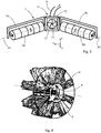
- the snow removal equipment 4 comprises two rotary brushes 5A, 5B, a means 6 for evacuating the snow accumulated between the two rotary brushes 5A, 5B and a structure 7 supporting the two rotary brushes 5A, 5B and the evacuation means. 6.
- a first rotary brush 5A comprises a first axis of rotation A1.
- a second rotary brush 5B comprises a second axis of rotation A2.
- the first axis of rotation A1 and the second axis of rotation extend generally in the XY plane.
- the first axis of rotation A1 forms with the second axis of rotation A2 a first non-zero angle ⁇ 1, that is to say that the two axes of rotation A1 and A2 are not parallel.
- the two rotary brushes are arranged in a "V".
- the two rotary brushes are positioned side by side respectively on the right and on the left of the operator.
- Each of the two rotary brushes is able to be driven in rotation by a drive means such as a hydraulic motor.
- the speed of rotation of the rotary brushes can be variable.
- the direction of rotation of each rotary broom is indicated by arrows F1 on the figure 3 .
- the direction of rotation is defined so that the snow accumulated between the two rotary brooms is moved upwards (and not folded against the ground), that is to say suspended in the air between the two rotary brushes 5A, 5B.
- Each of the two rotary brushes, or rotary brush comprises a generally cylindrical shape, formed by a set of radially extending bristles.
- the shape of each of the two rotary brushes 5A and 5B is identical. More precisely, as it appears on the figure 4 , each rotary brush 5A, 5B can comprise an assembly of rings 8 arranged side by side and contiguously. Each ring 8 can comprise a plurality of tufts of bristles 9 distributed around the periphery of the ring 8. The outer diameter D formed by these bristles 9 can be for example between 50cm and 100cm, in particular it can be approximately equal to 80cm. The length of each rotary broom along its axis of rotation can be adjusted by choosing a number of rings 8 placed side by side.
- each ring may have a length along its axis of rotation approximately equal to one meter and each rotary brush may include three rings placed end to end.
- the length of each rotary broom along its axis of rotation may be equal to approximately three meters. This length could however be different.
- the bristles can be made from polyester or any other cold and water resistant material suitable for moving snow.
- the figure 9 illustrates a particular arrangement of the bristles 9 in a helical pattern.
- the bristles are not distributed uniformly to constitute the cylindrical shape but are distributed in a plurality of rows parallel to each other and arranged in a helical pattern around the ring 8. Between each row is a volume devoid of hairs.
- the helical pattern is designed in coherence with the direction of rotation of the rotary brush so as to produce an apparent displacement of the bristles 9 in the direction of the discharge means 6, that is to say towards the inner end of the rotary brush.
- the rotation of a rotary broom contributes not only to moving the snow upwards but also towards the evacuation means 6.
- the evacuation means 6 is positioned between the two rotary brushes 5A, and 5B. It can be positioned substantially at the intersection between the first axis of rotation A1 and the second axis of rotation A2, that is to say towards the point of the “V”.
- the evacuation means comprises a suction means, in particular a rotating propeller 10 (which can also be referred to as a “turbine”), and an evacuation pipe 11 for the snow.
- the propeller 10 can rotate about an axis of rotation substantially parallel to the longitudinal axis X. It can extend substantially to the inner ends of the two rotary brushes 5A, 5B.
- the propeller 10 can be driven in rotation by a motor so as to generate an air flow directed from the front to the rear. The air flow is guided towards the discharge pipe 11.
- the suction means could comprise more than a single propeller. For example two propellers arranged one above the other or one next to the other.
- the discharge pipe 11 is positioned downstream of the suction means. It comprises an inlet connected to the suction means, and an outlet 12 (visible on the figure 1 ) positioned outside the field between the two rotary brushes.
- the outlet 12 is positioned outside the surface included inside the "V" so that the snow ejected by the discharge pipe 11 does not fall between the two rotary brushes 5A, 5B.
- the orientation of the discharge pipe 11 can be modifiable so as to eject the snow to the right or to the left of the vehicle 1 as required.
- the evacuation means 6 is advantageously configured to eject snow to the right or to the left of the vehicle outside the ski slope.
- the evacuation means 6 can be advantageously configured to eject snow at a distance from the vehicle 1 greater than or equal to ten meters.
- the evacuation means 6 can also be configured to eject snow over a shorter distance, in particular right next to the vehicle 1.
- the snow could also be ejected towards a snow container attached to the vehicle.
- the structure 7, which can also be called a “frame”, can be a steel frame or any other sufficiently strong material. It breaks down into a first structure 7A supporting the first rotary broom, a second structure 7B supporting the second rotating broom and a third structure 7C supporting the discharge means 6 and a fixing means 13 to the frame 20 of the vehicle 1.
- the third structure 7C is positioned between the first structure 7A and the second structure 7B.
- the first structure 7A and the second structure 7B can take the form of an inverted U, each branch of which supports one end of the first and of the second rotary brush. Bearings can be provided at the interface between the structures 7A and 7B and the rotary brushes 5A and 5B.
- the fixing means 13 to the chassis 20 of the vehicle 1 may comprise a universal fixing interface or a fixing interface specific to a particular model or a particular brand of vehicle.
- the third structure 7C is rigidly fixed to the rest of the vehicle 1.
- the fixing means 13 may include a connector allowing to supply energy to the evacuation means and the rotary brushes to make them turn.
- the fixing means 13 may be removable so as to be able to assemble or disassemble the snow removal equipment from the chassis 20 of the vehicle 1.
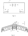
- the figure 10 illustrates a fixing means 13 according to one embodiment of the invention.
- the fixing means 13 comprises on the one hand two hooks 18A, 18B oriented so as to be able to be hung on the same horizontal bar integral with the chassis 20 of the vehicle.
- the fixing means 13 comprises two fixing bolts 19A, 19B mounted free to rotate respectively around the axes Z1 and Z2, both parallel to the axis Z.
- the two hooks 18A, 18B are positioned substantially towards the center. of the third structure 7C.
- the two fixing bolts 19A, 19B are mounted respectively on the right side and on the left side of the third structure 7C.
- This fixing means has the advantage of being identical to the fixing means provided on certain blades used for the maintenance of ski slopes. Thus, it is easy to equip a ski slope preparation vehicle with the snow removal equipment 6 by removing the blade initially fixed and mounting the snow removal equipment 6 in place of the blade.
- the third structure 7C comprises at its lower edge a scraper strip 17, or scraper flap, intended to scrape the first layer C1, under the discharge means 6, during the passage of the snow removal equipment.
- This scraper belt can be made from rubber or any other equivalent material, which is both flexible and strong.
- the first structure 7A and the second structure 7B can be articulated with respect to the third structure 7C as we will detail below.
- the first rotary brush is orientable about a first adjustment axis R1 substantially perpendicular to the XY plane on which the vehicle 1 moves.
- the adjustment axis R1 can be positioned at the interface between the first rotary brush 5A and the means evacuation 6, that is to say at the interface between the first structure 7A and the third structure 7C.
- the second rotary brush 5B is orientable about a second adjustment axis R2 substantially perpendicular to the XY plane.
- the first adjustment axis R1 and the second adjustment axis R2 are therefore parallel to the Z axis.
- the modification of the orientation of the rotary brushes around the adjustment axes R1 and / or R2 leads to a modification of the first angle ⁇ 1.
- a first adjustment means and a second adjustment means make it possible to respectively modify the orientation of the first rotary brush 5A and of the second rotary brush 5B around the adjustment axes R1 and R2.
- a single adjustment means can simultaneously adjust the orientation of the first rotary brush and of the second rotary brush so that the bisector of the first angle ⁇ 1 remains parallel to the axis X whatever the value of this angle.
- the snow removal equipment includes a first wheel 14A attached to the outer end of the first structure 7A.
- the first wheel 14A is able to rest and roll on the first layer C1 of hard snow or ice under the second layer C2 of fresh snow.
- the position of the first wheel 14A is adjustable in height, that is to say along the axis Z with respect to the first structure 7A.
- a mechanism comprising a crank can be provided for the height adjustment of the first wheel.
- the first wheel 14A may be of the jockey wheel type of a trailer of a particular vehicle.
- the snow removal equipment also includes a second wheel 14B identical to the first wheel 14A and symmetrically attached to the second structure 7B.
- the first rotary brush can also be movable parallel to the first adjustment axis R1.
- the assembly formed by the first structure 7A and the first brush 5A can therefore move in translation parallel to the Z axis with respect to the third structure 7C.
- a sliding link can be arranged at the interface between the first structure 7A and the third structure 7C.
- the second rotary brush can also be movable parallel to the second adjustment axis R2.
- a third adjustment means and a fourth adjustment means such as hydraulic jacks and / or motors, make it possible to modify the height of the first rotary brush 5A and of the second rotary brush 5B parallel to the adjustment axes R1 and R2 respectively. .
- the first rotary brush 5A can be orientable about a third adjustment axis R3 belonging to the XY plane and perpendicular to the first axis of rotation A1.
- the assembly formed by the first structure 7A and the first brush 5A can therefore pivot about the adjustment axis R3 relative to the third structure 7C.
- the first axis of rotation A1 can thus form a second non-zero angle ⁇ 2 with the XY plane.
- a pivot connection can be arranged at the interface between the first structure 7A and the third structure 7C.
- the second 5B rotary brush can be orientable about a fourth adjustment axis R4 belonging to the XY plane and perpendicular to the first axis of rotation A1.
- the second axis of rotation A2 can thus form a third non-zero angle ⁇ 3 with the XY plane.
- a fifth adjustment means and a sixth adjustment means such as hydraulic jacks and / or motors, make it possible to respectively modify the orientation of the first rotary brush 5A and of the second rotary brush 5B around the adjustment axes R3 and R4.
- the snow removal equipment can include three separate joints for each rotary broom 5A, 5B.
- a first articulation is obtained by the rotation of the rotary brushes around the adjustment axes R1 and R2.
- a second articulation is obtained by the displacement of the rotary brushes parallel to the adjustment axes R1 and R2.
- a third articulation is obtained by the rotation of the rotary brushes around the adjustment axes R3 and R4.
- Each of these three joints can be left free, be mechanically adjusted, or they can be controlled by the operator via a man-machine interface or they can be controlled automatically by a PLC to which suitable sensors are connected.
- the second and third articulations are left free, that is to say that the rotary brushes are mounted "floating".
- the snow removal equipment could include only one one or only two articulations for each of the rotary brushes among the three articulations presented.
- the third structure 7C can also be mounted free to slide parallel to the axis Z.
- Wheels 21A, 21B (in particular two wheels 21A, 21B on either side of the scraper belt 17) can advantageously support the third structure. These wheels 21A, 21B can rest on the first layer C1 of hard snow or ice under the second layer C2 of fresh snow.
- the wheels 21A, 21B can be adjustable in height to adjust a pressure of the scraper belt 17 on the layer C1 of hard snow. This ensures that the scraper belt 17 adopts a position which makes it possible to effectively scrape the fresh snow without however supporting the entire weight of the snow-clearing equipment, and therefore without suffering too much wear.
- An embodiment of the snow-clearing equipment equipped with the third structure 7C equipped with the wheels 21A, 21B is shown schematically in the figure. figure 11 .
- the figure 8 illustrates a partial view of a track 2 of the vehicle 1 according to one embodiment of the invention.
- the tracks are formed by an assembly of bars 15 extending parallel to the transverse axis Y.
- the track 2 also comprises shoes 16 fixed between each bar.
- the pads 16 are made of rubber or any other flexible material and adheres to the snow.
- the bars 15 act as crampons and provide the vehicle 1 with sufficient grip to progress on snow or ice.
- the pads 16 are arranged transversely between each bar and make it possible to reduce the height on which each bar sinks. in snow or ice.
- the pads 16 therefore protect the first layer C1 during the passage of the vehicle.
- Such pads can be used to equip the tracks of any ski slope preparation vehicle, even if they do not include snow removal equipment according to the invention. The use of such pads makes it possible to preserve the surface condition of a ski slope despite the passage of the vehicle 1.
- the second layer C2 of fresh snow forms on top of the first layer C1 of hard snow or ice constituting the ski competition track.
- the vehicle 1 provided with the snow removal equipment 4 then traverses the ski slope in forward motion so that the snow removal equipment sweeps the entire surface of the ski slope.
- the rotary brushes rotate and suspend the fresh snow constituting the second layer C2 between the two rotary brushes.
- the speed of rotation of the rotary brushes can be fixed, be automatically adjusted by a PLC or adjusted by the operator via a man-machine interface to effectively lift the snow constituting the second layer C2.
- the snow forming the second layer C2 is then stirred, destabilized and aerated by the action of the rotating brushes.
- V-shaped arrangement of the two rotary brushes and the helical arrangement of the bristles 9 guide the snow thus stirred towards the propeller 10 where it is sucked up.
- the snow is then driven out of the area delimited by the two rotary brooms via the discharge pipe 11.
- the scraper belt 17 the snow forming the second layer C2 cannot pass under the discharge means 6. In addition, this snow cannot escape through the small spaces between the rotary brushes 5A, 5B and the third structure 7C. Thus all the volume of snow forming the second layer C2 is effectively removed by the evacuation means 6.
- Snow removal equipment can also operate when the vehicle is moving downhill, or even when the vehicle is moving across the slope.
- the end of the bristles 9 of the rotary brushes comes into contact with the first layer C1.
- the contact of the end of the bristles on the layer C1 can be obtained by the own weight of each rotary brush and the structures 7A and 7B or else by a controlled movement of the structures 7A and 7B.
- the first layer C1 is sufficiently hard and / or the bristles 9 are sufficiently flexible so that the rotary brushes do not damage the first layer C1.
- the adjustment of their height parallel to the Z axis makes it possible to control the pressure of the bristles on the first layer C1 and therefore the wear of these bristles.
- the value of the first angle ⁇ 1 can be adjusted.
- the first and second adjustment means can be actuated to define a value of the first angle ⁇ 1 low so as to sweep a moderate weight of snow and avoid jamming of the means of escape 6 by snow.
- the second layer C2 consists of light snow, in other words not very humid, and / or in small quantity, it is possible to define a value of the first greater angle ⁇ 1 so as to sweep a large area and to carry out maintenance of the ski slope more quickly.
- each rotary brush may also be requested to best match the shape of the terrain.
- These joints can be controlled by actuating their adjustment means via a man-machine interface or they can be controlled automatically by a PLC to which suitable sensors are connected. These joints can also be left free. In this case, it is the stresses exerted by the snowpack on the rotary brushes which requests the second and third articulations.
- the pads 16 prevent the bars 15 from sinking deeply into the first layer C1.
- the first layer C1 is therefore not damaged or weakly marked by the passage of the vehicle 1.
- the pads 16 can be removed to provide the vehicle with increased grip on the snow-covered ground. .
- the invention it is possible to efficiently and quickly remove fresh snow deposited on a ski racing track.
- the time required to clear the snow therefore allows ski competitions to be maintained even when a snow shower occurs shortly before the scheduled time for the competition.
Landscapes
- Engineering & Computer Science (AREA)
- Architecture (AREA)
- Civil Engineering (AREA)
- Structural Engineering (AREA)
- Tires In General (AREA)
- Suspension Of Electric Lines Or Cables (AREA)
- Cleaning Of Streets, Tracks, Or Beaches (AREA)
Claims (13)
- Fahrzeug (1) zur Präparierung von Skipisten, dadurch gekennzeichnet, dass es ein Schneeräumgerät (4) aufweist, das aufweist:- zwei rotierende Bürsten (5A, 5B) und- eine Einrichtung zur Beseitigung (6) des zwischen den zwei rotierenden Bürsten (5A, 5B) angesammelten Schnees,wobei eine erste rotierende Bürste (5A) eine erste Rotationsachse (A1) aufweist, eine zweite rotierende Bürste (5B) eine zweite Rotationsachse (A2) aufweist, wobei die erste Rotationsachse (A1) mit der zweiten Rotationsachse (A2) einen ersten Winkel (β1) ungleich Null bildet.
- Fahrzeug (1) zur Präparierung von Skipisten nach dem vorhergehenden Anspruch, dadurch gekennzeichnet, dass die Beseitigungseinrichtung (6) im Wesentlichen am Schnittpunkt zwischen der ersten Rotationsachse (A1) und der zweiten Rotationsachse (A2) positioniert ist.
- Fahrzeug (1) zur Präparierung von Skipisten nach einem der vorhergehenden Ansprüche, dadurch gekennzeichnet, dass die Beseitigungseinrichtung (6) eine Ansaugeinrichtung, die im Wesentlichen am Schnittpunkt zwischen der ersten Rotationsachse (A1) und der zweiten Rotationsachse (A2) positioniert ist, insbesondere einen rotierenden Propeller (10), und/oder eine Beseitigungs-Rohrleitung (11) des Schnees aufweist, wobei die Beseitigungs-Rohrleitung (11) einen Ausgang (12) aufweist, der außerhalb eines zwischen den zwei rotierenden Bürsten (5A, 5B) befindlichen Bereichs positioniert ist.
- Fahrzeug (1) zur Präparierung von Skipisten nach dem vorhergehenden Anspruch, dadurch gekennzeichnet, dass die Ansaugeinrichtung einen rotierenden Propeller (10) aufweist, wobei der Propeller (10) um eine Achse parallel zu einer Längsachse (X) des Fahrzeugs (1) rotationsbeweglich ist.
- Fahrzeug (1) zur Präparierung von Skipisten nach einem der vorhergehenden Ansprüche, dadurch gekennzeichnet, dass die Beseitigungseinrichtung (6) konfiguriert ist, um Schnee nach außerhalb einer Skipiste auszuwerfen, unabhängig von der Position des Fahrzeugs (1) auf der Skipiste, insbesondere, dass die Beseitigungseinrichtung (6) konfiguriert ist, Schnee in eine Entfernung vom Fahrzeug (1) auszuwerfen, die größer als oder gleich zehn Meter ist.
- Fahrzeug (1) zur Präparierung von Skipisten nach einem der vorhergehenden Ansprüche, dadurch gekennzeichnet, dass die erste rotierende Bürste (5A) und/oder die zweite rotierende Bürste (58) eine global zylindrische Form aufweist, die von einer Einheit von Borsten (9) geformt wird, die sich radial erstrecken, insbesondere gemäß einem schraubenförmigen Muster, und insbesondere sind die Borsten (9) aus Polyester.
- Fahrzeug (1) zur Präparierung von Skipisten nach einem der vorhergehenden Ansprüche, dadurch gekennzeichnet, dass das Schneeräumgerät (4) eine die erste rotierende Bürste (5A) tragende erste Struktur (7A) und ein an der ersten Struktur (7A) befestigtes erstes Rad (14A) aufweist, das auf einer ersten Schicht (C1) harten Schnees oder Eis unter einer zweiten Schicht (C2) von Neuschnee aufliegen kann, wobei die Position des ersten Rads (14A) bezüglich der ersten Struktur (7A) in der Höhe eingestellt werden kann, und/oder dass das Schneeräumgerät (4) eine die zweite rotierende Bürste (5B) tragende zweite Struktur (7B) und ein an der zweiten Struktur (7B) befestigtes zweites Rad (14B) aufweist, das auf einer ersten Schicht (C1) harten Schnees oder Eis unter einer zweiten Schicht (C2) von Neuschnee aufliegen kann, wobei die Position des zweiten Rads (14B) bezüglich der zweiten Struktur (7B) in der Höhe eingestellt werden kann.
- Fahrzeug (1) zur Präparierung von Skipisten nach einem der vorhergehenden Ansprüche, dadurch gekennzeichnet, dass die erste rotierende Bürste (5A) um eine erste Einstellachse (R1) im Wesentlichen lotrecht zur Fläche einer ersten Schicht (C1) von hartem Schnee oder Eis unter einer zweiten Schicht (C2) von Neuschnee ausrichtbar ist, und/oder dass die zweite rotierende Bürste (5B) um eine zweite Einstellachse (R2) im Wesentlichen lotrecht zur Fläche einer ersten Schicht (C1) von hartem Schnee oder Eis unter einer zweiten Schicht (C2) von Neuschnee ausrichtbar ist.
- Fahrzeug (1) zur Präparierung von Skipisten nach einem der vorhergehenden Ansprüche, dadurch gekennzeichnet, dass die erste rotierende Bürste (5A) parallel zu einer ersten Einstellachse (R1) im Wesentlichen lotrecht zur Fläche einer ersten Schicht (C1) von hartem Schnee oder Eis unter einer zweiten Schicht (C2) von Neuschnee beweglich ist, und/oder um eine dritte Einstellachse (R3) im Wesentlichen parallel zur Fläche einer ersten Schicht (C1) von hartem Schnee oder Eis unter einer zweiten Schicht (C2) von Neuschnee ausrichtbar ist, und/oder dass die zweite rotierende Bürste (5B) parallel zu einer zweiten Einstellachse (R2) im Wesentlichen lotrecht zur Fläche einer ersten Schicht (C1) von hartem Schnee oder Eis unter einer zweiten Schicht (C2) von Neuschnee beweglich ist, und/oder um eine vierte Einstellachse (R4) im Wesentlichen parallel zur Fläche einer ersten Schicht (C1) von hartem Schnee oder Eis unter einer zweiten Schicht (C2) von Neuschnee ausrichtbar ist.
- Fahrzeug (1) zur Präparierung von Skipisten nach einem der vorhergehenden Ansprüche, dadurch gekennzeichnet, dass es eine entfernbare Befestigungseinrichtung (13) zur Befestigung des Schneeräumgeräts (4) an einem Fahrgestell (20) des Fahrzeugs (1) aufweist.
- Fahrzeug (1) zur Präparierung von Skipisten nach einem der vorhergehenden Ansprüche, dadurch gekennzeichnet, dass es Ketten (2) aufweist, die von einem Zusammenbau von Querstegen (15) und Kettengliedern (16) gebildet werden, insbesondere Kettenglieder (16) aus Kautschuk, die quer zwischen jedem Steg (15) angeordnet sind, um eine erste Schicht (C1) von hartem Schnee oder Eis zu schützen, auf der das Fahrzeug (1) sich bewegt.
- Betriebsverfahren eines Fahrzeugs (1) zur Präparierung von Skipisten nach einem der vorhergehenden Ansprüche, dadurch gekennzeichnet, dass es einen Schritt der Einstellung des zwischen der ersten Rotationsachse (A1) und der zweiten Rotationsachse (A2) gebildeten ersten Winkels (β1) abhängig von einer zu beseitigenden Schneemenge und/oder abhängig von einer Feuchtigkeit des zu beseitigenden Schnees aufweist.
- Betriebsverfahren eines Fahrzeugs (1) zur Präparierung von Skipisten nach Anspruch 9, dadurch gekennzeichnet, dass es einen Schritt der Beseitigung des Schnees mit der Beseitigungseinrichtung (6) aufweist, wobei die erste rotierende Bürste (5A) frei ist, sich als Reaktion auf eine Auflage der ersten rotierenden Bürste (5A) auf einer ersten Schicht C1 von hartem Schnee oder Eis unter einer zweiten Schicht (C2) von Neuschnee parallel zur ersten Einstellachse (R1) zu verschieben, und/oder die erste rotierende Bürste (5A) frei ist, sich als Reaktion auf eine Auflage der ersten rotierenden Bürste (5A) auf einer ersten Schicht C1 von hartem Schnee oder Eis unter einer zweiten Schicht (C2) von Neuschnee um die dritte Einstellachse (R3) auszurichten, und/oder die zweite rotierende Bürste (5B) frei ist, sich als Reaktion auf eine Auflage der zweiten rotierenden Bürste (5B) auf einer ersten Schicht C1 von hartem Schnee oder Eis unter einer zweiten Schicht (C2) von Neuschnee parallel zur zweiten Einstellachse (R2) zu verschieben, und/oder die zweite rotierende Bürste (5B) frei ist, sich als Reaktion auf eine Auflage der zweiten rotierenden Bürste (5B) auf einer ersten Schicht C1 von hartem Schnee oder Eis unter einer zweiten Schicht (C2) von Neuschnee um die vierte Einstellachse (R4) auszurichten.
Applications Claiming Priority (1)
| Application Number | Priority Date | Filing Date | Title |
|---|---|---|---|
| FR1858685A FR3086304B1 (fr) | 2018-09-25 | 2018-09-25 | Equipement de deneigement muni de deux balais rotatifs agences en v |
Publications (2)
| Publication Number | Publication Date |
|---|---|
| EP3628780A1 EP3628780A1 (de) | 2020-04-01 |
| EP3628780B1 true EP3628780B1 (de) | 2021-07-28 |
Family
ID=65243823
Family Applications (1)
| Application Number | Title | Priority Date | Filing Date |
|---|---|---|---|
| EP19199224.7A Active EP3628780B1 (de) | 2018-09-25 | 2019-09-24 | Pistenraupe mit schneebeseitigungsgerät |
Country Status (2)
| Country | Link |
|---|---|
| EP (1) | EP3628780B1 (de) |
| FR (1) | FR3086304B1 (de) |
Family Cites Families (4)
| Publication number | Priority date | Publication date | Assignee | Title |
|---|---|---|---|---|
| CH329289A (de) * | 1958-01-09 | 1958-04-30 | Peter Ag Konrad | Kehrmaschine für Fahrbahnen |
| FR2116956A5 (de) * | 1969-12-22 | 1972-07-21 | Bonato Bernardo | |
| IT1062806B (it) * | 1976-01-14 | 1985-02-11 | O M A N Officina Macchine E At | Veicolo battipista |
| SE535937C2 (sv) * | 2011-06-08 | 2013-02-26 | Railcare Group Ab | Förfarande och anordning vid borttagning av snö |
-
2018
- 2018-09-25 FR FR1858685A patent/FR3086304B1/fr not_active Expired - Fee Related
-
2019
- 2019-09-24 EP EP19199224.7A patent/EP3628780B1/de active Active
Also Published As
| Publication number | Publication date |
|---|---|
| FR3086304A1 (fr) | 2020-03-27 |
| EP3628780A1 (de) | 2020-04-01 |
| FR3086304B1 (fr) | 2021-04-09 |
Similar Documents
| Publication | Publication Date | Title |
|---|---|---|
| WO1988004394A1 (fr) | Procede d'enneigement de pistes artificielles de ski alpin ou nordique et moyens de mise en oeuvre du procede | |
| FR2957223A1 (fr) | Faneuse a fonctions d'andainage et d'epandage a decalage transversal | |
| WO2001087047A1 (fr) | Effeuilleuse, plus specialement destinee a l'effeuillage selectif de la vigne | |
| EP1976367B2 (de) | Bodenbearbeitungsmaschine in der art eines vertikalscheibenpfluges | |
| EP3628780B1 (de) | Pistenraupe mit schneebeseitigungsgerät | |
| FR2929488A1 (fr) | Appareil de nettoyage de terrain engazonne | |
| EP0366174B1 (de) | Maschine zum Aufsammeln von auf dem Boden liegenden Früchten oder dergleichen | |
| EP0560655B1 (de) | Verfahren und Maschine zum Pflegen einer Rasenfläche wie einer Pferderennbahn oder Pferdetrainingsbahn | |
| FR2618290A1 (fr) | Procede et machine pour le ramassage de produits, notamment de fruits sur le sol | |
| CA2079372C (fr) | Procede et machine pour deneiger une voie de circulation, qui utilisent une solution saline | |
| FR2681506A1 (fr) | Dispositif de ramassage de coquillages. | |
| FR2706734A1 (en) | Agricultural machine which makes it possible to pick up plastic films for mulching covering the cultivation beds | |
| FR2546710A1 (fr) | Dispositif et procede pour epandre des produits sur une surface, notamment epandeur d'engrais | |
| FR2608944A1 (fr) | Dispositif de projection controlee d'un fluide, tel que par exemple un produit herbicide, sur le sol | |
| FR3052956A1 (fr) | Dispositif de ramassage de fruits a terre, notamment de prunes | |
| FR2492621A1 (fr) | Machine pour l'entretien de terrains gazonnes notamment de terrains de sport | |
| BE896006A (fr) | Procede en vue d'ameliorer de maniere permanente le drainage superficiel des terrains, de preference, des terrains couverts d'herbe, et appareil pour la mise en oeuvre de ce procede | |
| EP1224854B1 (de) | Vorrichtung zum Sammeln von landwirtschaftlichen, am Boden liegenden Produkten, insbesondere von kleinen Früchten | |
| EP0053078A2 (de) | Verfahren und Vorrichtung zum Aufsammeln eines auf einen Strand frisch abgelagerten Verschmutzungsstoffes | |
| EP0059671B1 (de) | Einrichtung zum Sammeln und Reinigen der Ernte, insbesondere Rüben | |
| FR2720220A1 (fr) | Dispositif pour le ramassage sur le sol de produits agricoles de petites dimensions tels que des fruits. | |
| FR2543595A1 (fr) | Embarcation pour le nettoyage d'un egout ou canal d'evacuation de dechets analogue | |
| EP4376606A1 (de) | Vorrichtung zum spritzen von behandlungsmitteln für pflanzen | |
| FR2531837A1 (fr) | Appareil de desherbage par humectation | |
| FR2688376A1 (fr) | Rouleau de travail du sol et machine le comportant. |
Legal Events
| Date | Code | Title | Description |
|---|---|---|---|
| PUAI | Public reference made under article 153(3) epc to a published international application that has entered the european phase |
Free format text: ORIGINAL CODE: 0009012 |
|
| STAA | Information on the status of an ep patent application or granted ep patent |
Free format text: STATUS: THE APPLICATION HAS BEEN PUBLISHED |
|
| AK | Designated contracting states |
Kind code of ref document: A1 Designated state(s): AL AT BE BG CH CY CZ DE DK EE ES FI FR GB GR HR HU IE IS IT LI LT LU LV MC MK MT NL NO PL PT RO RS SE SI SK SM TR |
|
| AX | Request for extension of the european patent |
Extension state: BA ME |
|
| STAA | Information on the status of an ep patent application or granted ep patent |
Free format text: STATUS: REQUEST FOR EXAMINATION WAS MADE |
|
| 17P | Request for examination filed |
Effective date: 20200930 |
|
| RBV | Designated contracting states (corrected) |
Designated state(s): AL AT BE BG CH CY CZ DE DK EE ES FI FR GB GR HR HU IE IS IT LI LT LU LV MC MK MT NL NO PL PT RO RS SE SI SK SM TR |
|
| GRAP | Despatch of communication of intention to grant a patent |
Free format text: ORIGINAL CODE: EPIDOSNIGR1 |
|
| STAA | Information on the status of an ep patent application or granted ep patent |
Free format text: STATUS: GRANT OF PATENT IS INTENDED |
|
| INTG | Intention to grant announced |
Effective date: 20210219 |
|
| RIC1 | Information provided on ipc code assigned before grant |
Ipc: E01H 4/02 20060101AFI20210205BHEP Ipc: E01H 5/09 20060101ALN20210205BHEP |
|
| GRAS | Grant fee paid |
Free format text: ORIGINAL CODE: EPIDOSNIGR3 |
|
| GRAA | (expected) grant |
Free format text: ORIGINAL CODE: 0009210 |
|
| STAA | Information on the status of an ep patent application or granted ep patent |
Free format text: STATUS: THE PATENT HAS BEEN GRANTED |
|
| AK | Designated contracting states |
Kind code of ref document: B1 Designated state(s): AL AT BE BG CH CY CZ DE DK EE ES FI FR GB GR HR HU IE IS IT LI LT LU LV MC MK MT NL NO PL PT RO RS SE SI SK SM TR |
|
| REG | Reference to a national code |
Ref country code: GB Ref legal event code: FG4D Free format text: NOT ENGLISH |
|
| REG | Reference to a national code |
Ref country code: CH Ref legal event code: EP |
|
| REG | Reference to a national code |
Ref country code: AT Ref legal event code: REF Ref document number: 1414844 Country of ref document: AT Kind code of ref document: T Effective date: 20210815 |
|
| REG | Reference to a national code |
Ref country code: IE Ref legal event code: FG4D Free format text: LANGUAGE OF EP DOCUMENT: FRENCH |
|
| REG | Reference to a national code |
Ref country code: DE Ref legal event code: R096 Ref document number: 602019006400 Country of ref document: DE |
|
| REG | Reference to a national code |
Ref country code: LT Ref legal event code: MG9D |
|
| REG | Reference to a national code |
Ref country code: NL Ref legal event code: MP Effective date: 20210728 |
|
| PG25 | Lapsed in a contracting state [announced via postgrant information from national office to epo] |
Ref country code: SE Free format text: LAPSE BECAUSE OF FAILURE TO SUBMIT A TRANSLATION OF THE DESCRIPTION OR TO PAY THE FEE WITHIN THE PRESCRIBED TIME-LIMIT Effective date: 20210728 Ref country code: RS Free format text: LAPSE BECAUSE OF FAILURE TO SUBMIT A TRANSLATION OF THE DESCRIPTION OR TO PAY THE FEE WITHIN THE PRESCRIBED TIME-LIMIT Effective date: 20210728 Ref country code: ES Free format text: LAPSE BECAUSE OF FAILURE TO SUBMIT A TRANSLATION OF THE DESCRIPTION OR TO PAY THE FEE WITHIN THE PRESCRIBED TIME-LIMIT Effective date: 20210728 Ref country code: FI Free format text: LAPSE BECAUSE OF FAILURE TO SUBMIT A TRANSLATION OF THE DESCRIPTION OR TO PAY THE FEE WITHIN THE PRESCRIBED TIME-LIMIT Effective date: 20210728 Ref country code: LT Free format text: LAPSE BECAUSE OF FAILURE TO SUBMIT A TRANSLATION OF THE DESCRIPTION OR TO PAY THE FEE WITHIN THE PRESCRIBED TIME-LIMIT Effective date: 20210728 Ref country code: BG Free format text: LAPSE BECAUSE OF FAILURE TO SUBMIT A TRANSLATION OF THE DESCRIPTION OR TO PAY THE FEE WITHIN THE PRESCRIBED TIME-LIMIT Effective date: 20211028 Ref country code: HR Free format text: LAPSE BECAUSE OF FAILURE TO SUBMIT A TRANSLATION OF THE DESCRIPTION OR TO PAY THE FEE WITHIN THE PRESCRIBED TIME-LIMIT Effective date: 20210728 Ref country code: PT Free format text: LAPSE BECAUSE OF FAILURE TO SUBMIT A TRANSLATION OF THE DESCRIPTION OR TO PAY THE FEE WITHIN THE PRESCRIBED TIME-LIMIT Effective date: 20211129 Ref country code: NL Free format text: LAPSE BECAUSE OF FAILURE TO SUBMIT A TRANSLATION OF THE DESCRIPTION OR TO PAY THE FEE WITHIN THE PRESCRIBED TIME-LIMIT Effective date: 20210728 Ref country code: NO Free format text: LAPSE BECAUSE OF FAILURE TO SUBMIT A TRANSLATION OF THE DESCRIPTION OR TO PAY THE FEE WITHIN THE PRESCRIBED TIME-LIMIT Effective date: 20211028 |
|
| PG25 | Lapsed in a contracting state [announced via postgrant information from national office to epo] |
Ref country code: PL Free format text: LAPSE BECAUSE OF FAILURE TO SUBMIT A TRANSLATION OF THE DESCRIPTION OR TO PAY THE FEE WITHIN THE PRESCRIBED TIME-LIMIT Effective date: 20210728 Ref country code: LV Free format text: LAPSE BECAUSE OF FAILURE TO SUBMIT A TRANSLATION OF THE DESCRIPTION OR TO PAY THE FEE WITHIN THE PRESCRIBED TIME-LIMIT Effective date: 20210728 Ref country code: GR Free format text: LAPSE BECAUSE OF FAILURE TO SUBMIT A TRANSLATION OF THE DESCRIPTION OR TO PAY THE FEE WITHIN THE PRESCRIBED TIME-LIMIT Effective date: 20211029 |
|
| REG | Reference to a national code |
Ref country code: AT Ref legal event code: UEP Ref document number: 1414844 Country of ref document: AT Kind code of ref document: T Effective date: 20210728 |
|
| REG | Reference to a national code |
Ref country code: DE Ref legal event code: R119 Ref document number: 602019006400 Country of ref document: DE |
|
| PG25 | Lapsed in a contracting state [announced via postgrant information from national office to epo] |
Ref country code: DK Free format text: LAPSE BECAUSE OF FAILURE TO SUBMIT A TRANSLATION OF THE DESCRIPTION OR TO PAY THE FEE WITHIN THE PRESCRIBED TIME-LIMIT Effective date: 20210728 |
|
| REG | Reference to a national code |
Ref country code: BE Ref legal event code: MM Effective date: 20210930 |
|
| PG25 | Lapsed in a contracting state [announced via postgrant information from national office to epo] |
Ref country code: SM Free format text: LAPSE BECAUSE OF FAILURE TO SUBMIT A TRANSLATION OF THE DESCRIPTION OR TO PAY THE FEE WITHIN THE PRESCRIBED TIME-LIMIT Effective date: 20210728 Ref country code: SK Free format text: LAPSE BECAUSE OF FAILURE TO SUBMIT A TRANSLATION OF THE DESCRIPTION OR TO PAY THE FEE WITHIN THE PRESCRIBED TIME-LIMIT Effective date: 20210728 Ref country code: RO Free format text: LAPSE BECAUSE OF FAILURE TO SUBMIT A TRANSLATION OF THE DESCRIPTION OR TO PAY THE FEE WITHIN THE PRESCRIBED TIME-LIMIT Effective date: 20210728 Ref country code: MC Free format text: LAPSE BECAUSE OF FAILURE TO SUBMIT A TRANSLATION OF THE DESCRIPTION OR TO PAY THE FEE WITHIN THE PRESCRIBED TIME-LIMIT Effective date: 20210728 Ref country code: EE Free format text: LAPSE BECAUSE OF FAILURE TO SUBMIT A TRANSLATION OF THE DESCRIPTION OR TO PAY THE FEE WITHIN THE PRESCRIBED TIME-LIMIT Effective date: 20210728 Ref country code: CZ Free format text: LAPSE BECAUSE OF FAILURE TO SUBMIT A TRANSLATION OF THE DESCRIPTION OR TO PAY THE FEE WITHIN THE PRESCRIBED TIME-LIMIT Effective date: 20210728 Ref country code: AL Free format text: LAPSE BECAUSE OF FAILURE TO SUBMIT A TRANSLATION OF THE DESCRIPTION OR TO PAY THE FEE WITHIN THE PRESCRIBED TIME-LIMIT Effective date: 20210728 |
|
| PLBE | No opposition filed within time limit |
Free format text: ORIGINAL CODE: 0009261 |
|
| STAA | Information on the status of an ep patent application or granted ep patent |
Free format text: STATUS: NO OPPOSITION FILED WITHIN TIME LIMIT |
|
| 26N | No opposition filed |
Effective date: 20220429 |
|
| PG25 | Lapsed in a contracting state [announced via postgrant information from national office to epo] |
Ref country code: LU Free format text: LAPSE BECAUSE OF NON-PAYMENT OF DUE FEES Effective date: 20210924 Ref country code: IE Free format text: LAPSE BECAUSE OF NON-PAYMENT OF DUE FEES Effective date: 20210924 Ref country code: DE Free format text: LAPSE BECAUSE OF NON-PAYMENT OF DUE FEES Effective date: 20220401 Ref country code: BE Free format text: LAPSE BECAUSE OF NON-PAYMENT OF DUE FEES Effective date: 20210930 |
|
| PGFP | Annual fee paid to national office [announced via postgrant information from national office to epo] |
Ref country code: FR Payment date: 20220922 Year of fee payment: 4 |
|
| PGFP | Annual fee paid to national office [announced via postgrant information from national office to epo] |
Ref country code: IT Payment date: 20220930 Year of fee payment: 4 |
|
| PGFP | Annual fee paid to national office [announced via postgrant information from national office to epo] |
Ref country code: CH Payment date: 20220926 Year of fee payment: 4 |
|
| PG25 | Lapsed in a contracting state [announced via postgrant information from national office to epo] |
Ref country code: CY Free format text: LAPSE BECAUSE OF FAILURE TO SUBMIT A TRANSLATION OF THE DESCRIPTION OR TO PAY THE FEE WITHIN THE PRESCRIBED TIME-LIMIT Effective date: 20210728 |
|
| PG25 | Lapsed in a contracting state [announced via postgrant information from national office to epo] |
Ref country code: HU Free format text: LAPSE BECAUSE OF FAILURE TO SUBMIT A TRANSLATION OF THE DESCRIPTION OR TO PAY THE FEE WITHIN THE PRESCRIBED TIME-LIMIT; INVALID AB INITIO Effective date: 20190924 |
|
| PG25 | Lapsed in a contracting state [announced via postgrant information from national office to epo] |
Ref country code: MK Free format text: LAPSE BECAUSE OF FAILURE TO SUBMIT A TRANSLATION OF THE DESCRIPTION OR TO PAY THE FEE WITHIN THE PRESCRIBED TIME-LIMIT Effective date: 20210728 |
|
| REG | Reference to a national code |
Ref country code: CH Ref legal event code: PL |
|
| GBPC | Gb: european patent ceased through non-payment of renewal fee |
Effective date: 20230924 |
|
| PG25 | Lapsed in a contracting state [announced via postgrant information from national office to epo] |
Ref country code: TR Free format text: LAPSE BECAUSE OF FAILURE TO SUBMIT A TRANSLATION OF THE DESCRIPTION OR TO PAY THE FEE WITHIN THE PRESCRIBED TIME-LIMIT Effective date: 20210728 |
|
| PG25 | Lapsed in a contracting state [announced via postgrant information from national office to epo] |
Ref country code: GB Free format text: LAPSE BECAUSE OF NON-PAYMENT OF DUE FEES Effective date: 20230924 |
|
| PG25 | Lapsed in a contracting state [announced via postgrant information from national office to epo] |
Ref country code: CH Free format text: LAPSE BECAUSE OF NON-PAYMENT OF DUE FEES Effective date: 20230930 |
|
| PG25 | Lapsed in a contracting state [announced via postgrant information from national office to epo] |
Ref country code: GB Free format text: LAPSE BECAUSE OF NON-PAYMENT OF DUE FEES Effective date: 20230924 Ref country code: FR Free format text: LAPSE BECAUSE OF NON-PAYMENT OF DUE FEES Effective date: 20230930 Ref country code: CH Free format text: LAPSE BECAUSE OF NON-PAYMENT OF DUE FEES Effective date: 20230930 |