EP3628603A1 - Outil de montage d'attache de câble, procédé de montage d'attache de câble - Google Patents
Outil de montage d'attache de câble, procédé de montage d'attache de câble Download PDFInfo
- Publication number
- EP3628603A1 EP3628603A1 EP18196954.4A EP18196954A EP3628603A1 EP 3628603 A1 EP3628603 A1 EP 3628603A1 EP 18196954 A EP18196954 A EP 18196954A EP 3628603 A1 EP3628603 A1 EP 3628603A1
- Authority
- EP
- European Patent Office
- Prior art keywords
- cable tie
- path portion
- downstream
- jaw
- strap
- Prior art date
- Legal status (The legal status is an assumption and is not a legal conclusion. Google has not performed a legal analysis and makes no representation as to the accuracy of the status listed.)
- Granted
Links
- 238000000034 method Methods 0.000 title claims description 12
- 238000011144 upstream manufacturing Methods 0.000 claims abstract description 68
- 230000007246 mechanism Effects 0.000 claims abstract description 57
- 238000003780 insertion Methods 0.000 claims abstract description 24
- 230000037431 insertion Effects 0.000 claims abstract description 24
- 230000000694 effects Effects 0.000 description 5
- 238000010276 construction Methods 0.000 description 4
- 230000002093 peripheral effect Effects 0.000 description 3
- 238000004904 shortening Methods 0.000 description 3
- 230000007704 transition Effects 0.000 description 3
- 230000008859 change Effects 0.000 description 2
- 230000001419 dependent effect Effects 0.000 description 2
- 238000010586 diagram Methods 0.000 description 2
- 230000009471 action Effects 0.000 description 1
- 230000006978 adaptation Effects 0.000 description 1
- 238000005452 bending Methods 0.000 description 1
- 230000008901 benefit Effects 0.000 description 1
- 230000003247 decreasing effect Effects 0.000 description 1
- 230000001939 inductive effect Effects 0.000 description 1
- 230000000977 initiatory effect Effects 0.000 description 1
- 230000000284 resting effect Effects 0.000 description 1
- 238000012800 visualization Methods 0.000 description 1
Images


Classifications
-
- B—PERFORMING OPERATIONS; TRANSPORTING
- B65—CONVEYING; PACKING; STORING; HANDLING THIN OR FILAMENTARY MATERIAL
- B65B—MACHINES, APPARATUS OR DEVICES FOR, OR METHODS OF, PACKAGING ARTICLES OR MATERIALS; UNPACKING
- B65B13/00—Bundling articles
- B65B13/02—Applying and securing binding material around articles or groups of articles, e.g. using strings, wires, strips, bands or tapes
- B65B13/04—Applying and securing binding material around articles or groups of articles, e.g. using strings, wires, strips, bands or tapes with means for guiding the binding material around the articles prior to severing from supply
- B65B13/06—Stationary ducts or channels
-
- B—PERFORMING OPERATIONS; TRANSPORTING
- B65—CONVEYING; PACKING; STORING; HANDLING THIN OR FILAMENTARY MATERIAL
- B65B—MACHINES, APPARATUS OR DEVICES FOR, OR METHODS OF, PACKAGING ARTICLES OR MATERIALS; UNPACKING
- B65B13/00—Bundling articles
- B65B13/02—Applying and securing binding material around articles or groups of articles, e.g. using strings, wires, strips, bands or tapes
- B65B13/025—Hand-held tools
- B65B13/027—Hand-held tools for applying straps having preformed connecting means, e.g. cable ties
-
- B—PERFORMING OPERATIONS; TRANSPORTING
- B65—CONVEYING; PACKING; STORING; HANDLING THIN OR FILAMENTARY MATERIAL
- B65B—MACHINES, APPARATUS OR DEVICES FOR, OR METHODS OF, PACKAGING ARTICLES OR MATERIALS; UNPACKING
- B65B13/00—Bundling articles
- B65B13/18—Details of, or auxiliary devices used in, bundling machines or bundling tools
- B65B13/185—Details of tools
-
- B—PERFORMING OPERATIONS; TRANSPORTING
- B65—CONVEYING; PACKING; STORING; HANDLING THIN OR FILAMENTARY MATERIAL
- B65B—MACHINES, APPARATUS OR DEVICES FOR, OR METHODS OF, PACKAGING ARTICLES OR MATERIALS; UNPACKING
- B65B13/00—Bundling articles
- B65B13/18—Details of, or auxiliary devices used in, bundling machines or bundling tools
- B65B13/20—Means for compressing or compacting bundles prior to bundling
-
- B—PERFORMING OPERATIONS; TRANSPORTING
- B65—CONVEYING; PACKING; STORING; HANDLING THIN OR FILAMENTARY MATERIAL
- B65B—MACHINES, APPARATUS OR DEVICES FOR, OR METHODS OF, PACKAGING ARTICLES OR MATERIALS; UNPACKING
- B65B13/00—Bundling articles
- B65B13/18—Details of, or auxiliary devices used in, bundling machines or bundling tools
- B65B13/24—Securing ends of binding material
- B65B13/34—Securing ends of binding material by applying separate securing members, e.g. deformable clips
-
- B—PERFORMING OPERATIONS; TRANSPORTING
- B65—CONVEYING; PACKING; STORING; HANDLING THIN OR FILAMENTARY MATERIAL
- B65B—MACHINES, APPARATUS OR DEVICES FOR, OR METHODS OF, PACKAGING ARTICLES OR MATERIALS; UNPACKING
- B65B27/00—Bundling particular articles presenting special problems using string, wire, or narrow tape or band; Baling fibrous material, e.g. peat, not otherwise provided for
- B65B27/10—Bundling rods, sticks, or like elongated objects
-
- B—PERFORMING OPERATIONS; TRANSPORTING
- B65—CONVEYING; PACKING; STORING; HANDLING THIN OR FILAMENTARY MATERIAL
- B65B—MACHINES, APPARATUS OR DEVICES FOR, OR METHODS OF, PACKAGING ARTICLES OR MATERIALS; UNPACKING
- B65B35/00—Supplying, feeding, arranging or orientating articles to be packaged
- B65B35/10—Feeding, e.g. conveying, single articles
- B65B35/16—Feeding, e.g. conveying, single articles by grippers
- B65B35/18—Feeding, e.g. conveying, single articles by grippers by suction-operated grippers
-
- B—PERFORMING OPERATIONS; TRANSPORTING
- B65—CONVEYING; PACKING; STORING; HANDLING THIN OR FILAMENTARY MATERIAL
- B65B—MACHINES, APPARATUS OR DEVICES FOR, OR METHODS OF, PACKAGING ARTICLES OR MATERIALS; UNPACKING
- B65B57/00—Automatic control, checking, warning, or safety devices
- B65B57/02—Automatic control, checking, warning, or safety devices responsive to absence, presence, abnormal feed, or misplacement of binding or wrapping material, containers, or packages
- B65B57/04—Automatic control, checking, warning, or safety devices responsive to absence, presence, abnormal feed, or misplacement of binding or wrapping material, containers, or packages and operating to control, or to stop, the feed of such material, containers, or packages
-
- B—PERFORMING OPERATIONS; TRANSPORTING
- B65—CONVEYING; PACKING; STORING; HANDLING THIN OR FILAMENTARY MATERIAL
- B65B—MACHINES, APPARATUS OR DEVICES FOR, OR METHODS OF, PACKAGING ARTICLES OR MATERIALS; UNPACKING
- B65B59/00—Arrangements to enable machines to handle articles of different sizes, to produce packages of different sizes, to vary the contents of packages, to handle different types of packaging material, or to give access for cleaning or maintenance purposes
- B65B59/02—Arrangements to enable adjustments to be made while the machine is running
Definitions
- the present invention relates to the field of mounting cable ties, for example when assembling cable harnesses.
- cable harnesses a plurality and possibly many cables are assembled and are affixed to each other via cable ties to be attached.
- Fig. 7 shows such a known tool, available as "Autotool 2000 CPK” from Hellerman Tyton.
- Figs. 7a, b and c show subsequent operation states of the known tool. It comprises a tool body and a head end at the left side of the figures, the head end having two movable jaws 71 and 72.
- the jaws are dimensioned and adapted to surround and confine between them the items to be tied, such as a bundle of cables or the like.
- the jaws are open, and through the opening, the tool can be moved onto the bundle to be tied such that the jaws 71, 72 have the bundle in-between. Then, first, the upper jaw is lowered to close the loop.
- a guidance path for a cable tie is formed on the inner peripheral wall of the loop .
- 73 is a magazine for new cable ties.
- the cable ties are fed onto the guidance path strap-end first, which is, in Fig. 7 , a clockwise direction starting at the upper right arcuate corner of the opening, going from there downward, then horizontal leftward, then upward and then rightward back to the starting point.
- the cable tie is placed such that the strap end is located immediately adjacent and opposite the receiving opening of the strap head. In this position, the strap head is held firmly in place. Then, the strap end is further fed through the head opening such that a tightening mechanism can grab the free end and tighten the cable tie. Thereafter, the free end is usually cut-off.
- Cable ties may come in different lengths, for example 100 mm, 110 mm, 120 mm and so on up to 180 mm and more. If a tool such as shown in figure 7 should handle such different lengths, for achieving the situation that, before insertion of the strap end into the strap head, the strap end should be positioned immediately opposite of and adjacent to the strap head, the inner circumferential length of the loop around the inner surfaces of the jaws must be changed for adapting it to the cable tie length. In tools similar to that shown in figure 7 this is made by exchanging the jaws for obtaining the appropriate length of the inner circumference. This requires time to be done and manpower.
- An aspect of the prior art is further that when feeding the strap end through the strap head by the action of the lower jaw 71, this jaw must push the strap end along the stationary upper jaw 72 against the frictional forces occurring along the length of the guidance portion in upper jaw 72. This increases frictional force and leads to increased wear of tool components.
- a cable tie mounting tool comprises an upstream and a downstream jaw having concave guidance path portions for the strap of a cable tie, a placing mechanism adapted to place a cable tie portion along the common concave guidance path by pushing it strap-end-first along the common concave guidance path starting at the upstream end of the upstream jaw and pushing it in downstream direction, an insertion mechanism for feeding the cable tie strap end of the placed cable tie through the head of the placed cable tie, and a tightening mechanism for tightening the cable tie. Also provided is a length adjustment mechanism for adjusting the length of the common concave guidance path.
- upstream and downstream are relative to the movement direction of a cable tie strap along the guidance path. Downstream is the direction along which the cable tie strap moves when it is inserted, and upstream is the opposite direction from which the cable tie comes when inserted.
- the placing mechanism may be adapted and act such that when the cable tie is placed, its free strap end rests immediately opposite of and adjacent to the strap receiving opening in the cable tie head. The distance then may be below 5 mm or below 2 mm. The insertion mechanism pushes the strap end finally through the strap head. Downstream of the head, the free end of the cable tie strap will be caught by some kind of tightening mechanism and can then also be cut-off after having been tightened.
- the length adjustment mechanism is provided such that the inner circumference length of the loop formed by the closed jaws of the tool can selectively be shortened compared to a possible maximum length. This can be achieved by pushing path portions radially inward such that a long loop portion is more or less shortcut.
- "Radial” here refers to a direction in the loop plane towards or away from a point in the centre region of the loop. A radial movement shall be a movement having a predominant radial component.
- the guidance path for the cable tie needs not continuously be provided along the entire length of the cable tie strap.
- Cable tie straps have a certain rigidity and thus can reach across gaps in the path e.g. from one guidance path portion to another guidance path portion. This will be explained more in detail further down this specification. As far as guidance path lengths are considered, these lengths can include gaps amongst path portions, to be taken into account as they are bridged by a traveling cable tie strap.
- the cable ties as provided are usually straight and must be bent into loop form. Accordingly, the cable tie guidance path provided around the inner periphery of the loop formed by the closed jaws is radially outward, and the guided cable tie strap is radially inward and forced to bend into loop shape by the concave shape of the various guidance path portions.
- the length adjustment mechanism can automatically be operated and can, for a series of cable ties to be attached, be set once such that the inner circumferential length of the mentioned loop formed by the jaws is such that the strap end comes to rest immediately opposite of, and adjacent to, the opening in the strap head of the cable tie.
- the provision of the length adjustment mechanism makes the change of the jaws for the adaptation to different cable tie lengths superfluous.
- Both the length adjustment mechanism and the insertion mechanism may comprise at one of the jaws a pivotable path portion.
- Their pivot axis may be perpendicular to the plane of the opening confined by the closed jaws, so that pivoting around this pivot takes place in the plane of the opening area.
- the arrangements may be such that the pivoting is radially inward into the opening or radially outward.
- both insertion and length adjustment shorten the length of the inner peripheral length of the loop of the cable tie strap. Shortening can be achieved by pushing guidance path portions radially inward so that a possible longer loop geometry is selectively shortcut.
- a particular advantage is achieved when the pivotable path portions used for length adjustment and used for insertion are the same, adapted to make the two movements for respective path shortenings as required. Then, only one movable part is required for accomplishing the two functions of path length adjustment and insertion of the cable tie end into the cable tie head. The drive of this portion is then adapted to make the respective movements when and as required. Driving may be made by a controller, preferably a digital controller.
- pivotable path portions for insertion and for length adjustment may be different distinct path portions and may individually be driven as appropriate in space and time.
- the jaws may be of concave shape, and likewise the pivotable path portions as well as the other path portions provided by the various components of the tool can be of concave shape. In cooperation, they form a concave guidance for the cable tie strap, forcing the strap into loop shape such that the strap end reaches back into the opening of the strap head.
- the guidance path may have gaps. It is not required that it supports the cable tie strap without interruptions. Likewise, it may have certain edges or portions of low radius of curvature. It needs not be circular and may have another appropriate contour.
- the guidance path portions may cross each other under a desired angle.
- insertion direction of the strap into the head is more or less perpendicular to the direction of the strap portion immediately formed at the head.
- the guidance path portions will have, at the insertion point, a corresponding angle, i.e. substantially rectangular or corresponding to the insertion direction of the strap end into the strap head, possibly with some deviation from said direction that may be below ⁇ 20° or ⁇ 10°.
- the pivot of the pivotable path portion is provided at the upstream end of the pivotable path portion, so that the downstream end thereof is freely movable within its other constructive constraints around said pivot.
- the pivotable path portion of the length adjustment mechanism is provided at the downstream jaw. This again reduces reactionary forces when using the pivotable path portion particularly for inserting the cable tie strap end into the cable tie head.
- the pivotable path portion of the length adjustment mechanism is pivotably attached to the upstream end of the downstream jaw. This minimizes the reactionary forces when reducing the loop circumference by pivoting the pivotable path portion.
- the drive mechanism of the pivotable path portion is adapted to drive individual steps of said pivotable path portions as required. Particularly, it may adjust, in a first step for reducing the peripheral length of the loop provided by the closed jaws, the length to a value corresponding to the strap length of a presently used cable tie. Then, when using the tool for actual cable tie mounting, this general setting may be maintained, and further circumference reducing steps may be driven for inserting the cable tie strap end into the cable tie head.
- the first step for length adjustment may be an absolute step in the sense that it is selected in dependence of the cable tie length to be handled, whereas the second inserting step may be an incremental step for pushing the cable tie strap end through the cable tie head to an extent such that a tightening mechanism downstream of the cable tie head can catch the cable tie strap end for tightening it.
- the guidance path portions of the upstream jaw and of the downstream jaw have different lengths.
- the length adjustment mechanism is preferably provided at the jaw having the longer of the two guidance path portions. This gives sufficient room for the pivotable path portion to provide for sufficient dimensional variation of the loop circumference for shortening/adjusting the guidance path length and for inserting the strap end into the head.
- this jaw preferably also has a fixed path portion cooperating with the pivotable path portion. All these path portions can be held by a holder of concave contour.
- the holder itself must be concave because also the holder must reach around the items to be tied.
- the holder may hold the pivot of the pivotable path portion and may hold the fixed path portion in fixed and well-defined manner in relation to the pivotable path portion.
- the pivot of the pivotable path portion may sit at the upstream end of the holder when it is all provided at the downstream jaw.
- the free - downstream - end of the pivotable path portion points to a fixed path portion and will guide the cable tie strap towards varying positions along the fixed guidance path depending on the pivoting position of the pivoting path portion.
- a variable gap may be provided between the downstream end of the pivotable path portion and the fixed path portion, depending on the pivot position of the pivotable path portion.
- the fixed path portion is designed such that it securely catches the arriving free end of the cable tie strap and then guides it downstream.
- One or more of the guidance path portions may have a U-shaped cross-sectional contour with a flat bottom for receiving the strap of the cable tie.
- the U-shaped contour may be shallow and have relatively short legs. Generally speaking, the length of the legs can be selected such that on the one hand side the cable tie strap is safely caught and guided and is prevented from escaping sideways, but is preferably kept small enough for avoiding unnecessary increase of frictional forces and other unwanted effects.
- the sidewalls of the guidance path portions profile may be relatively high where the guidance path has small radii of curvature because the likelihood of escaping is higher at such portions.
- a method for automatically mounting a cable tie by a tool around items to be tied comprises the following steps:
- Step (1) may be executed semiautomatically, for example by manually selecting a setting from a menu, the selected setting then being set automatically, or may be made manually by adjusting the common guidance path portion to the length of the cable ties to be used.
- Step (3) can be made automatically, e.g. by a robot holding and moving the tool, or manually by a worker working with the tool along a harness for attaching the required cable ties.
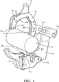
- Fig. 1 shows the head part of a tool for mounting cable ties. Not shown are several components of the tool that are required for its operation, such as a tool body, a supply mechanism for the cable ties, a cutting mechanism, a tightening mechanism, operating switches, drives and the like.
- Fig. 1 shows the jaw portion of the tool as it may sit on the left side of an appropriately adapted tool as substantially shown in Fig. 7 instead of the jaws 71, 72 shown there.
- Reference numeral 10 symbolizes the items to be tied by a cable tie. For simplification it is drawn as a cylinder, but usually it is a bunch of cables, tubes and the like to be tied together.
- 11 is the upstream jaw with its upstream end 11u and its downstream end 11d.
- Numerals 12, 13 and 14 constitute together the downstream jaw with its upstream end 12u and its downstream end 12d. Both are shown to be pivotable around their respective pivots 11p and 12p. Their pivoting movement is used for opening and closing the jaws, opening being such that the downstream end 11d of the upstream jaw 11 and the upstream end 12u of the downstream jaw 12, 13, 14 are remote from each other so that the items to be tied 10 can get into the opening defined by the two jaws.
- the upstream jaw 11 defines and forms an upstream guidance path 99a.
- the downstream jay 12, 13, 14 defines and forms a downstream guidance path 99b, 99c.
- the guidance path is for guiding the strap 62 of a cable tie 61 -63..
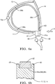
- Fig. 6 shows schematically the situation where a cable tie 61, 62, 63 is placed along the guidance path 99 constituted by the guidance path portions 99a, 99b, 99c.
- Fig. 6 shows the strap portion 62 of the cable tie a little bit radially inward distant from the guidance path portions 99a, 99b, 99c. But in real operation, the strap portion 62 will abut at least along long portions of the guidance path 99, noting that at certain portions, particularly at edgy portions of the overall guidance path 99, it may lift off from the guidance path.
- 61 is the cable tie head with the opening therein indicated by the dashed channel 61a.
- the situation in Fig. 6 is a situation where the cable tie strap end 63 is placed opposite of and immediately adjacent to the cable tie head 61, particularly the opening 61a therein. This is achieved by the operation of a not shown insertion mechanism for the cable tie into the guidance path which may sit upstream of the upstream end of the upstream jaw. The insertion direction and insertion position of the cable tie towards the guidance path 99 is indicated by arrow H in Fig. 6a .
- 64 symbolizes a tightening device. It may consist of rollers catching the end once reaching through the opening 61a and may tighten it and pull it as far as pre-set criteria allow it.
- 65 symbolizes a cutting tool for cutting off the tail end at the downstream side of the cable tie head 61.
- the support 15 symbolizes a support in the sense of a fixation point and may be seen as a part of the overall machine or machine body carrying the mentioned components. Particularly, the pivots 11p and 12p are attached to support 15.
- the support may consist of plural members fixedly or movably attached to each other.
- the downstream jaw 12, 13, 14 may be formed by one or more holders 12, 121, 12r.
- Fig. 1 shows a left side holder 121 and a right side holder 12r between which members are held that contribute to forming the guidance path. All the jaws 11, 12, 13, 14, guidance path portions 99a, 99b, 99c and holders 121, 12r are of concave shape such that they encompass an opening in which the items to be tied 10 come to rest once the jaws are closed.
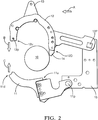
- Fig. 2 shows the situation of Fig. 1 in side view.
- arrows A, B and C indicate certain movements.
- the tool may be brought towards the item to be tied 10 along the direction indicate by arrow A.
- the jaws are open as shown, but will, once the correct position is taken, be closed along the directions of arrows B and C.
- the Figures show constructions where both jaws are movable/pivotable, it may well be that only one of them is movable/pivotable. Instead of pivoting movements, also translational movements could be considered.
- Fig. 3 shows the jaws in a closed state. Then, the downstream end 11d of the upstream jaw 11 is close to, and possibly abuts at, the upstream end 12u of the downstream jaw 12, 13, 14.
- Fig. 3 also shows schematically various drives. It shows drives 17 for the downstream jaw 12, 13, 14, and drive 18 for the upstream jaw 11. They may be distinct drives, possibly individually controllable, or may be attachments to a common gear or the like. Fig. 3 shows an embodiment where the drives 17, 18 of the jaws 11, 12, 13, 14 could individually be controlled by a controller 19. But as said, also other constructions are conceivable. Fig. 3 further shows a drive 16 for the pivotable path portion 13, 99b, pivoting, in the shown embodiment, around its pivot 13p at the upstream end 12u of the downstream jaw 12, 13, 14. Drive 16 may be a linear drive attached to a lever 13a extending radially outward away from the pivotable path portion 13. The linear drive may push the lever 13a in horizontal direction in Fig.
- 16b indicates the attachment of the drive 16 to the tool at a certain appropriate location. Attachment may be at the tool body as symbolized by support 15, but could also be rigid with respect to a portion of the downstream jaw 12-14, for example at holders 12r and/or 12l.
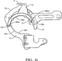
- FIG. 4a , 4b and 4c Various operational states of the pivoting path portion 13, 99b will now be described with reference to Figs. 4a , 4b and 4c .
- Said figures do not show the various drives. But they are provided as explained with reference to figure 3 .
- Figs. 4a , 4b , 4c show only the jaws 11, 12, 13, 14, with the right side holder 12r of fig. 1 left away for the sake of a clear visualization.
- the items to be tied 10 are not shown in Figs. 4a , 4b and 4c , although they are present during regular use.
- the pivotable path portion 13, 99b comprises a rail-like member 13b of concave shape bearing on its concave inner surface the actual guidance path portion 99b that is pivotable and has an upstream end 99bu and a downstream end 99bd.
- the pivot 13p is at the upstream end of the pivotable path portion 13, 99b and is also at the upstream end of the downstream jaw 12, 13, 14, as shown.
- the two path portions 99a of the upstream jaw 11 and 99b of the pivotable path portion 13, 99b are more or less contiguous, and a cable tie strap pushed along said path in downstream direction, i.e. from the upstream end 11u of the upstream jaw 11 and then travelling in clockwise direction in Fig. 4a , will easily and reliably pass the transition between the path portions 99a and 99b.
- the upstream path portion 99a is shown by dashed lines. It can be understood as being hidden behind the sidewalls for sideways confining and guiding a strap travelling along the guidance path. Substantially the same applies with respect to the fixed guidance path portion 99c,
- the pivotable path portion 13, 99b is shown in the most retracted position, i.e. radially most outward position during regular use. This implies also that the lever 13a is, in Fig. 4a , in its left most position during regular use. In such a position, the inner holder contour of the holders 12l, 12r may be the confining contour of the opening defined by the closed jaws and surrounding the items to be tied 10. In this position, the length of the overall guidance path 99a, 99b, 99c is maximum because the guidance path runs along the maximum loop dimension in the downstream jaw 12, 13, 14.
- Figs. 1 , 2 , 3 , 4a , 4b and 4c show that the downstream jaw 12, 13, 14 has the overall longer guidance path portion constituted by the two path portions 99b, 99c of the pivotable path portion 13, 99b and the fixed path portion 14, 99c. Together, they are longer than the guidance path portion 99a of the upstream jaw 11.
- the downstream path portions define, together a bent similar to a U-shape or horseshoe, bending a cable tie running around said path portion for around 180°, or more general between 140° and 220°.
- the upstream jaw 11 has the shorter path portion 99a, which bends the cable tie strap for a lower angle which may below 110° or below 90° or below 80°.
- the downstream jaw may hold the shorter path portion and the upstream jaw may carry the longer path portion, and could then also carry the pivotable path portion, then again pivotably held at its upstream end.
- Fig. 4b shows the pivotable path portion 13, 99b in a more inwardly pivoted position.
- the lever 13a was pushed by the not shown drive 16 in the direction of arrow D, i.e. rightward in Fig. 4b , this leading to a corresponding downward movement of the downstream end 99bd of the pivotable path portion along the direction of arrow E.
- the tangential extension of the downstream end of the pivotable path portion points to another position along the fixed path portion 99c.
- a gap between the two path portions widens. But the situation is still such that the leading end of the travelling cable tie strap 62 will reliably be caught by the fixed path portion 99c for further guidance there.
- the transition between it and the upstream path portion 99a is more edgy than in Fig. 4a , but still such that it can be passed by the leading portion 63 of the cable tie strap 62.
- Fig. 4b the guidance path length is decreased because the pivoted path portion "shortcuts" the maximum loop so that the overall length becomes shorter.
- the positioning shown in Fig. 4a could be suitable for the longest possible cable ties
- the positioning of Fig. 4b could be suitable either for shorter cable ties before inserting their free end into the head of the cable tie, or could be suitable for inserting the end of the longest possible cable tie into its head.
- the movements indicated by Fig. 4b were induced by the not shown drive 16, possibly under control of controller 19.
- Fig. 4c shows an again further pivoted position of the pivotable path portion 13, 99b.
- an edge occurs at the transition between upstream path portion 99a and pivotable path portion 13, 99b.
- constructions can be made such that a passing end 63 of a cable tie strap 62 reliably gets across the edge.
- the gap between it and the downstream fixed path portion 99c has increased.
- the arrangement is such that the leading end 63 of a cable tie strap 62 will safely be caught by the fixed path portion 99c.
- Movement of the pivotable path portion 13, 99b was such that the lever was again moved rightward as indicated by the direction of arrow F, and the downstream end 99bd thereof travelled downward along the of arrow G. Through this further pivoted position an even greater portion of the maximum available opening is shortcut, so that the guidance path length has again decrease compared to Fig. 4b and Fig. 4a .
- the position shown in Fig. 4c is the most inward position of the pivotable path portion 13, 99b during regular use, it is a position assumed when the end of a cable tie strap has been pushed through the cable tie head for a short strap length. Again, the movements indicated by Fig. 4c were induced by the not shown drive 16, possibly under control of controller 19.
- Fig. 5 is a diagram for showing operational methods of the described tool.
- the abscissa 51 shows qualitatively various pivoting positions P1, P2, ..., P8, Pmin of the pivotable path portion 13, 99.
- P1 is most outward, Pmin most inward.
- the ordinate 52 shows elapsed time. It may be assumed that P1 correspond to the position shown in Fig. 4a , and, for example, P5 is the position shown in Fig. 4b , and Pmin is the position shown in Fig. 4c . More distinct positions than those shown in Fig. 4a , 4b and 4c are possible and are indicated in Fig. 5 by the intermediate positions on the abscissa.
- the control may be such that these pivoting positions can be selected and then adjusted by drive 16.
- a slightly reduced guidance path length corresponding to position P3 would be suitable for positioning the cable tie strap end right opposite of and adjacent to the opening in the cable tie head. It is further assumed, that position P5 would be the position sufficient for inserting the cable tie strap end into and through the cable tie head and into the reach of a tightening mechanism.
- a first step 53-1 the pivotable path portion is brought to position P3. Then, or before that, the tool can be brought to the mounting side and the jaws can be closed. Then, the cable tie is inserted into the guidance path. Once this is achieved, a movement 53-2 of the pivotable path portion towards position P5 follows for pushing the cable tie strap end 63 through the cable tie head 61 toward the reach of the tightening mechanism 64. Once this is done, the pivotable path portion retracts by movement 53-3. Then, the jaws are opened, the tool is displaced to a new mounting site, the jaws are closed and then the reversing operation between positions » P5 » P3 is repeated by movements 53-4 and 53-5.
- the reversing movements 53-2 to 53-5 are relatively short since they must cover only the distance necessary for the cable tie end 63 to travel from the position immediately in front of the cable tie head opening 61a through said opening towards the reach of the tightening mechanism 64. This may be called work time tw of jaws, as indicated in Fig. 5 .
- the dead time td is the time required for operating the jaws, namely opening and closing them, and displacing the tool as required.
- Fig. 5 an example is assumed where the shortest possible cable tie is used, a position P8 being suitable for placing the tie. Then, a relatively long guidance path adjustment step 53-10 towards position P8 is required, and from there on the reversing movements between P8 and P9min ensues as described earlier. On the time line, after making the first adjustment towards position P8, the same timings as mentioned earlier are required.
- Fig. 6a shows the situation after a cable tie 61, 62, 63 has been placed along the guidance path 99 and before the required insertion activity is executed, this activity corresponding to movements 53-2 and 53-4 in Fig. 5 .
- Fig. 5 shows another operation method.
- the guidance path length may always be the same, i.e. maximum, irrespective of how long or short the used cable ties are.
- the reversing steps for pushing the cable tie strap end through the cable tie head opening 61a into the reach of a downstream tightening mechanism 64 may have different length depending on the length of the cable tie. Short cable ties will require a longer step, whereas longer cable ties will require a shorter step.
- position P7 is the position required for feeding the cable tie strap end through the cable tie head 61a into the reach of the tightening mechanism 64. Then, the reversing movements are longer. This increases the work time tw. The dead time td, however, remains the same.
- the longer reversing operations are shown with reference numerals 53-6, 53-7, 53-8 and 53-9.
- provisions must be taken for appropriately setting the target position P7. This may be made by a suitable control or may be accomplished by some kind of self-adjusting mechanism, such as force dependent, or may be feedback controlled, or the like.
- Fig. 6b is a cross section of the various guidance path portions 99a, 99b, 99c the downward direction in Fig. 6b is the radial outward direction of the loop formed by the guidance path.
- 62 is the cross section through the cable tie strap it abuts to the radial inside surface of the respective components, particularly upstream jaw 11, pivotable path portion 13, fixed path portion 14.
- Sidewalls 66, 67 maybe provided over parts or the entire length of the path portions for avoiding sideways escape, which would be, in Fig. 6a , vertical to the drawing plane.
- the sidewalls 66, 67 may be formed by the holders 12l, 12r, and would then be separate members.
- the described tool may be adapted for handling cable ties of variable length, for example with a minimum length of 90 mm or 100 mm or 110 mm, and/or with a maximum length of 220 mm or 200 mm or 180 mm.
- the length of the inner circumference of the loop defined by the closed jaws and the pivotable path portion may thus be adjusted for handling said lengths.
- the length adjustment mechanism may be adapted to reduce the guidance path length from its maximum to a length below 80% or below 70% or below 60% of the maximum length.
Landscapes
- Engineering & Computer Science (AREA)
- Mechanical Engineering (AREA)
- Basic Packing Technique (AREA)
Priority Applications (6)
| Application Number | Priority Date | Filing Date | Title |
|---|---|---|---|
| EP18196954.4A EP3628603B1 (fr) | 2018-09-26 | 2018-09-26 | Outil de montage d'attache de câble, procédé de montage d'attache de câble |
| RS20211213A RS62396B1 (sr) | 2018-09-26 | 2018-09-26 | Alat za montažu kablovskih vezica, postupak za montažu kablovskih vezica |
| US16/555,280 US11485529B2 (en) | 2018-09-26 | 2019-08-29 | Cable tie mounting tool and cable tie mounting method |
| KR1020190116557A KR102359194B1 (ko) | 2018-09-26 | 2019-09-23 | 케이블 타이 장착 도구, 케이블 타이 장착 방법 |
| CN201910904034.6A CN110949723B (zh) | 2018-09-26 | 2019-09-24 | 线缆绑带安装工具和线缆绑带安装方法 |
| JP2019175412A JP6997154B2 (ja) | 2018-09-26 | 2019-09-26 | ケーブルタイ装着工具、ケーブルタイ装着方法 |
Applications Claiming Priority (1)
| Application Number | Priority Date | Filing Date | Title |
|---|---|---|---|
| EP18196954.4A EP3628603B1 (fr) | 2018-09-26 | 2018-09-26 | Outil de montage d'attache de câble, procédé de montage d'attache de câble |
Publications (2)
| Publication Number | Publication Date |
|---|---|
| EP3628603A1 true EP3628603A1 (fr) | 2020-04-01 |
| EP3628603B1 EP3628603B1 (fr) | 2021-08-18 |
Family
ID=63762207
Family Applications (1)
| Application Number | Title | Priority Date | Filing Date |
|---|---|---|---|
| EP18196954.4A Active EP3628603B1 (fr) | 2018-09-26 | 2018-09-26 | Outil de montage d'attache de câble, procédé de montage d'attache de câble |
Country Status (6)
| Country | Link |
|---|---|
| US (1) | US11485529B2 (fr) |
| EP (1) | EP3628603B1 (fr) |
| JP (1) | JP6997154B2 (fr) |
| KR (1) | KR102359194B1 (fr) |
| CN (1) | CN110949723B (fr) |
| RS (1) | RS62396B1 (fr) |
Cited By (1)
| Publication number | Priority date | Publication date | Assignee | Title |
|---|---|---|---|---|
| EP4393829A1 (fr) * | 2022-12-08 | 2024-07-03 | HellermannTyton GmbH | Dispositif d'alimentation pour guider et fournir des liens d'une seule pièce |
Families Citing this family (2)
| Publication number | Priority date | Publication date | Assignee | Title |
|---|---|---|---|---|
| CN112591182B (zh) * | 2020-12-09 | 2022-04-15 | 西安航空职业技术学院 | 一种齿轮齿条啮合传动的无人高空捆扎机及使用方法 |
| CN113830620B (zh) * | 2021-09-06 | 2023-01-31 | 杭州太希智能科技有限公司 | 韧性线紧密成方绕线机、紧密绕线卷方扎带机及韧性线紧密绕线成方并扎带方法 |
Citations (3)
| Publication number | Priority date | Publication date | Assignee | Title |
|---|---|---|---|---|
| US4534817A (en) * | 1983-04-08 | 1985-08-13 | Sullivan Denis P O | Automatic bundle-tying tool |
| US5205328A (en) * | 1992-03-18 | 1993-04-27 | Panduit Corp. | Portable cable tie tool |
| EP0722885A1 (fr) * | 1995-01-18 | 1996-07-24 | Panduit Corporation | Outil portable pour installer des colliers de serrage sur des câbles |
Family Cites Families (12)
| Publication number | Priority date | Publication date | Assignee | Title |
|---|---|---|---|---|
| GB8907143D0 (en) | 1989-03-30 | 1989-05-10 | Bowthorpe Hellermann Ltd | Automatic tie gun |
| US5042635A (en) | 1989-10-02 | 1991-08-27 | Jani Supplies Enterprises, Inc. | Rapid coin acceptor |
| DE59000226D1 (de) | 1989-11-15 | 1992-09-03 | Hellermann Gmbh P | Band und werkzeug zum umschlingen und spannen um langgestreckte gegenstaende. |
| JP2938617B2 (ja) | 1991-05-14 | 1999-08-23 | アマノ株式会社 | 結束装置 |
| JP2002240804A (ja) | 2001-02-15 | 2002-08-28 | Naonobu Tatebayashi | 結束バンドの結束装置 |
| CN200964188Y (zh) * | 2006-10-31 | 2007-10-24 | 江阴圆方机械制造有限公司 | 棒材、管材打捆机的抱紧装置 |
| DE102013222924A1 (de) * | 2013-11-11 | 2015-05-28 | Hellermann Tyton Gmbh | Portables Kabelbindewerkzeug |
| CN107472575B (zh) * | 2015-08-11 | 2019-04-23 | 许修义 | 一种自动扎带工具的尾料排出结构 |
| CN206031857U (zh) * | 2016-02-05 | 2017-03-22 | 许修义 | 一种自动导引穿孔机构 |
| JP6673041B2 (ja) * | 2016-06-15 | 2020-03-25 | マックス株式会社 | 園芸用結束機 |
| US20190248521A1 (en) * | 2018-02-12 | 2019-08-15 | Panduit Corp. | Portable Cable Tie Tool |
| CN108945564B (zh) * | 2018-08-27 | 2024-06-25 | 深圳市施威德自动化科技有限公司 | 一种自动扎带工具的工作头 |
-
2018
- 2018-09-26 RS RS20211213A patent/RS62396B1/sr unknown
- 2018-09-26 EP EP18196954.4A patent/EP3628603B1/fr active Active
-
2019
- 2019-08-29 US US16/555,280 patent/US11485529B2/en active Active
- 2019-09-23 KR KR1020190116557A patent/KR102359194B1/ko active IP Right Grant
- 2019-09-24 CN CN201910904034.6A patent/CN110949723B/zh active Active
- 2019-09-26 JP JP2019175412A patent/JP6997154B2/ja active Active
Patent Citations (3)
| Publication number | Priority date | Publication date | Assignee | Title |
|---|---|---|---|---|
| US4534817A (en) * | 1983-04-08 | 1985-08-13 | Sullivan Denis P O | Automatic bundle-tying tool |
| US5205328A (en) * | 1992-03-18 | 1993-04-27 | Panduit Corp. | Portable cable tie tool |
| EP0722885A1 (fr) * | 1995-01-18 | 1996-07-24 | Panduit Corporation | Outil portable pour installer des colliers de serrage sur des câbles |
Cited By (1)
| Publication number | Priority date | Publication date | Assignee | Title |
|---|---|---|---|---|
| EP4393829A1 (fr) * | 2022-12-08 | 2024-07-03 | HellermannTyton GmbH | Dispositif d'alimentation pour guider et fournir des liens d'une seule pièce |
Also Published As
| Publication number | Publication date |
|---|---|
| JP6997154B2 (ja) | 2022-01-17 |
| KR20200035355A (ko) | 2020-04-03 |
| US20200094999A1 (en) | 2020-03-26 |
| KR102359194B1 (ko) | 2022-02-04 |
| EP3628603B1 (fr) | 2021-08-18 |
| CN110949723B (zh) | 2022-03-01 |
| US11485529B2 (en) | 2022-11-01 |
| RS62396B1 (sr) | 2021-10-29 |
| JP2020075762A (ja) | 2020-05-21 |
| CN110949723A (zh) | 2020-04-03 |
Similar Documents
| Publication | Publication Date | Title |
|---|---|---|
| EP3628603B1 (fr) | Outil de montage d'attache de câble, procédé de montage d'attache de câble | |
| RU2427458C2 (ru) | Устройство для соединения стержней | |
| US7143792B2 (en) | Reinforcing steel bar tying machine | |
| KR20070120564A (ko) | 사각형 와이어 권선 장치 | |
| US20050236509A1 (en) | Method and apparatus for winding field coils for dynamo-electric machines | |
| JP6321406B2 (ja) | Oリング取付装置および方法 | |
| KR102184898B1 (ko) | 수동 결속 공구 | |
| JP2012035290A (ja) | 線材の矯正装置 | |
| US10890002B2 (en) | Binding machine | |
| EP2704551A2 (fr) | Ligne de production de greffes de plantes | |
| JP2013022672A (ja) | 把持爪、ハンド、ハンド対および把持装置 | |
| JPH06198346A (ja) | 曲げ加工方法および曲げ加工装置 | |
| US5299480A (en) | Method for cutting workpieces using a shuttle vise | |
| US20120017732A1 (en) | Wire-processing machine with length-compensating unit | |
| US20180345345A1 (en) | Coiled material passing device and coiled material passing method | |
| JP2016056669A (ja) | クリップ装着装置 | |
| JP6454218B2 (ja) | チューブ切断装置 | |
| US5429158A (en) | Tool for binding an object, especially a cable harness | |
| JP5014851B2 (ja) | 切断機構を備えた曲げ加工装置 | |
| WO2015098522A1 (fr) | Dispositif d'envoi de terminaux | |
| CN104786230A (zh) | 柔性夹持手爪 | |
| US11597548B2 (en) | Binding machine | |
| JP6539494B2 (ja) | チューブ切断装置 | |
| KR101711164B1 (ko) | 자동매듭장치 | |
| US5672283A (en) | Apparatus and method for making welded mesh forms |
Legal Events
| Date | Code | Title | Description |
|---|---|---|---|
| PUAI | Public reference made under article 153(3) epc to a published international application that has entered the european phase |
Free format text: ORIGINAL CODE: 0009012 |
|
| STAA | Information on the status of an ep patent application or granted ep patent |
Free format text: STATUS: THE APPLICATION HAS BEEN PUBLISHED |
|
| AK | Designated contracting states |
Kind code of ref document: A1 Designated state(s): AL AT BE BG CH CY CZ DE DK EE ES FI FR GB GR HR HU IE IS IT LI LT LU LV MC MK MT NL NO PL PT RO RS SE SI SK SM TR |
|
| AX | Request for extension of the european patent |
Extension state: BA ME |
|
| STAA | Information on the status of an ep patent application or granted ep patent |
Free format text: STATUS: REQUEST FOR EXAMINATION WAS MADE |
|
| 17P | Request for examination filed |
Effective date: 20201001 |
|
| RBV | Designated contracting states (corrected) |
Designated state(s): AL AT BE BG CH CY CZ DE DK EE ES FI FR GB GR HR HU IE IS IT LI LT LU LV MC MK MT NL NO PL PT RO RS SE SI SK SM TR |
|
| GRAP | Despatch of communication of intention to grant a patent |
Free format text: ORIGINAL CODE: EPIDOSNIGR1 |
|
| STAA | Information on the status of an ep patent application or granted ep patent |
Free format text: STATUS: GRANT OF PATENT IS INTENDED |
|
| RIC1 | Information provided on ipc code assigned before grant |
Ipc: B65B 59/02 20060101ALI20210217BHEP Ipc: B65B 57/00 20060101ALI20210217BHEP Ipc: B65B 13/02 20060101AFI20210217BHEP Ipc: B65B 13/18 20060101ALI20210217BHEP Ipc: B65B 57/04 20060101ALI20210217BHEP |
|
| INTG | Intention to grant announced |
Effective date: 20210309 |
|
| GRAS | Grant fee paid |
Free format text: ORIGINAL CODE: EPIDOSNIGR3 |
|
| GRAA | (expected) grant |
Free format text: ORIGINAL CODE: 0009210 |
|
| STAA | Information on the status of an ep patent application or granted ep patent |
Free format text: STATUS: THE PATENT HAS BEEN GRANTED |
|
| AK | Designated contracting states |
Kind code of ref document: B1 Designated state(s): AL AT BE BG CH CY CZ DE DK EE ES FI FR GB GR HR HU IE IS IT LI LT LU LV MC MK MT NL NO PL PT RO RS SE SI SK SM TR |
|
| REG | Reference to a national code |
Ref country code: GB Ref legal event code: FG4D |
|
| REG | Reference to a national code |
Ref country code: CH Ref legal event code: EP |
|
| REG | Reference to a national code |
Ref country code: DE Ref legal event code: R096 Ref document number: 602018021932 Country of ref document: DE |
|
| REG | Reference to a national code |
Ref country code: IE Ref legal event code: FG4D Ref country code: AT Ref legal event code: REF Ref document number: 1421441 Country of ref document: AT Kind code of ref document: T Effective date: 20210915 |
|
| REG | Reference to a national code |
Ref country code: RO Ref legal event code: EPE |
|
| REG | Reference to a national code |
Ref country code: LT Ref legal event code: MG9D |
|
| REG | Reference to a national code |
Ref country code: NL Ref legal event code: MP Effective date: 20210818 |
|
| REG | Reference to a national code |
Ref country code: AT Ref legal event code: MK05 Ref document number: 1421441 Country of ref document: AT Kind code of ref document: T Effective date: 20210818 |
|
| PG25 | Lapsed in a contracting state [announced via postgrant information from national office to epo] |
Ref country code: AT Free format text: LAPSE BECAUSE OF FAILURE TO SUBMIT A TRANSLATION OF THE DESCRIPTION OR TO PAY THE FEE WITHIN THE PRESCRIBED TIME-LIMIT Effective date: 20210818 Ref country code: BG Free format text: LAPSE BECAUSE OF FAILURE TO SUBMIT A TRANSLATION OF THE DESCRIPTION OR TO PAY THE FEE WITHIN THE PRESCRIBED TIME-LIMIT Effective date: 20211118 Ref country code: LT Free format text: LAPSE BECAUSE OF FAILURE TO SUBMIT A TRANSLATION OF THE DESCRIPTION OR TO PAY THE FEE WITHIN THE PRESCRIBED TIME-LIMIT Effective date: 20210818 Ref country code: NO Free format text: LAPSE BECAUSE OF FAILURE TO SUBMIT A TRANSLATION OF THE DESCRIPTION OR TO PAY THE FEE WITHIN THE PRESCRIBED TIME-LIMIT Effective date: 20211118 Ref country code: PT Free format text: LAPSE BECAUSE OF FAILURE TO SUBMIT A TRANSLATION OF THE DESCRIPTION OR TO PAY THE FEE WITHIN THE PRESCRIBED TIME-LIMIT Effective date: 20211220 Ref country code: SE Free format text: LAPSE BECAUSE OF FAILURE TO SUBMIT A TRANSLATION OF THE DESCRIPTION OR TO PAY THE FEE WITHIN THE PRESCRIBED TIME-LIMIT Effective date: 20210818 Ref country code: HR Free format text: LAPSE BECAUSE OF FAILURE TO SUBMIT A TRANSLATION OF THE DESCRIPTION OR TO PAY THE FEE WITHIN THE PRESCRIBED TIME-LIMIT Effective date: 20210818 Ref country code: ES Free format text: LAPSE BECAUSE OF FAILURE TO SUBMIT A TRANSLATION OF THE DESCRIPTION OR TO PAY THE FEE WITHIN THE PRESCRIBED TIME-LIMIT Effective date: 20210818 Ref country code: FI Free format text: LAPSE BECAUSE OF FAILURE TO SUBMIT A TRANSLATION OF THE DESCRIPTION OR TO PAY THE FEE WITHIN THE PRESCRIBED TIME-LIMIT Effective date: 20210818 |
|
| PG25 | Lapsed in a contracting state [announced via postgrant information from national office to epo] |
Ref country code: PL Free format text: LAPSE BECAUSE OF FAILURE TO SUBMIT A TRANSLATION OF THE DESCRIPTION OR TO PAY THE FEE WITHIN THE PRESCRIBED TIME-LIMIT Effective date: 20210818 Ref country code: LV Free format text: LAPSE BECAUSE OF FAILURE TO SUBMIT A TRANSLATION OF THE DESCRIPTION OR TO PAY THE FEE WITHIN THE PRESCRIBED TIME-LIMIT Effective date: 20210818 Ref country code: GR Free format text: LAPSE BECAUSE OF FAILURE TO SUBMIT A TRANSLATION OF THE DESCRIPTION OR TO PAY THE FEE WITHIN THE PRESCRIBED TIME-LIMIT Effective date: 20211119 |
|
| PG25 | Lapsed in a contracting state [announced via postgrant information from national office to epo] |
Ref country code: NL Free format text: LAPSE BECAUSE OF FAILURE TO SUBMIT A TRANSLATION OF THE DESCRIPTION OR TO PAY THE FEE WITHIN THE PRESCRIBED TIME-LIMIT Effective date: 20210818 |
|
| PG25 | Lapsed in a contracting state [announced via postgrant information from national office to epo] |
Ref country code: DK Free format text: LAPSE BECAUSE OF FAILURE TO SUBMIT A TRANSLATION OF THE DESCRIPTION OR TO PAY THE FEE WITHIN THE PRESCRIBED TIME-LIMIT Effective date: 20210818 |
|
| REG | Reference to a national code |
Ref country code: CH Ref legal event code: PL |
|
| REG | Reference to a national code |
Ref country code: DE Ref legal event code: R097 Ref document number: 602018021932 Country of ref document: DE |
|
| REG | Reference to a national code |
Ref country code: BE Ref legal event code: MM Effective date: 20210930 |
|
| PG25 | Lapsed in a contracting state [announced via postgrant information from national office to epo] |
Ref country code: SM Free format text: LAPSE BECAUSE OF FAILURE TO SUBMIT A TRANSLATION OF THE DESCRIPTION OR TO PAY THE FEE WITHIN THE PRESCRIBED TIME-LIMIT Effective date: 20210818 Ref country code: SK Free format text: LAPSE BECAUSE OF FAILURE TO SUBMIT A TRANSLATION OF THE DESCRIPTION OR TO PAY THE FEE WITHIN THE PRESCRIBED TIME-LIMIT Effective date: 20210818 Ref country code: MC Free format text: LAPSE BECAUSE OF FAILURE TO SUBMIT A TRANSLATION OF THE DESCRIPTION OR TO PAY THE FEE WITHIN THE PRESCRIBED TIME-LIMIT Effective date: 20210818 Ref country code: EE Free format text: LAPSE BECAUSE OF FAILURE TO SUBMIT A TRANSLATION OF THE DESCRIPTION OR TO PAY THE FEE WITHIN THE PRESCRIBED TIME-LIMIT Effective date: 20210818 Ref country code: CZ Free format text: LAPSE BECAUSE OF FAILURE TO SUBMIT A TRANSLATION OF THE DESCRIPTION OR TO PAY THE FEE WITHIN THE PRESCRIBED TIME-LIMIT Effective date: 20210818 Ref country code: AL Free format text: LAPSE BECAUSE OF FAILURE TO SUBMIT A TRANSLATION OF THE DESCRIPTION OR TO PAY THE FEE WITHIN THE PRESCRIBED TIME-LIMIT Effective date: 20210818 |
|
| PLBE | No opposition filed within time limit |
Free format text: ORIGINAL CODE: 0009261 |
|
| STAA | Information on the status of an ep patent application or granted ep patent |
Free format text: STATUS: NO OPPOSITION FILED WITHIN TIME LIMIT |
|
| 26N | No opposition filed |
Effective date: 20220519 |
|
| PG25 | Lapsed in a contracting state [announced via postgrant information from national office to epo] |
Ref country code: LU Free format text: LAPSE BECAUSE OF NON-PAYMENT OF DUE FEES Effective date: 20210926 Ref country code: IT Free format text: LAPSE BECAUSE OF FAILURE TO SUBMIT A TRANSLATION OF THE DESCRIPTION OR TO PAY THE FEE WITHIN THE PRESCRIBED TIME-LIMIT Effective date: 20210818 Ref country code: IE Free format text: LAPSE BECAUSE OF NON-PAYMENT OF DUE FEES Effective date: 20210926 Ref country code: BE Free format text: LAPSE BECAUSE OF NON-PAYMENT OF DUE FEES Effective date: 20210930 |
|
| PG25 | Lapsed in a contracting state [announced via postgrant information from national office to epo] |
Ref country code: SI Free format text: LAPSE BECAUSE OF FAILURE TO SUBMIT A TRANSLATION OF THE DESCRIPTION OR TO PAY THE FEE WITHIN THE PRESCRIBED TIME-LIMIT Effective date: 20210818 Ref country code: LI Free format text: LAPSE BECAUSE OF NON-PAYMENT OF DUE FEES Effective date: 20210930 Ref country code: CH Free format text: LAPSE BECAUSE OF NON-PAYMENT OF DUE FEES Effective date: 20210930 |
|
| P01 | Opt-out of the competence of the unified patent court (upc) registered |
Effective date: 20230424 |
|
| PG25 | Lapsed in a contracting state [announced via postgrant information from national office to epo] |
Ref country code: CY Free format text: LAPSE BECAUSE OF FAILURE TO SUBMIT A TRANSLATION OF THE DESCRIPTION OR TO PAY THE FEE WITHIN THE PRESCRIBED TIME-LIMIT Effective date: 20210818 |
|
| PG25 | Lapsed in a contracting state [announced via postgrant information from national office to epo] |
Ref country code: HU Free format text: LAPSE BECAUSE OF FAILURE TO SUBMIT A TRANSLATION OF THE DESCRIPTION OR TO PAY THE FEE WITHIN THE PRESCRIBED TIME-LIMIT; INVALID AB INITIO Effective date: 20180926 |
|
| PGFP | Annual fee paid to national office [announced via postgrant information from national office to epo] |
Ref country code: TR Payment date: 20230925 Year of fee payment: 6 Ref country code: RO Payment date: 20230829 Year of fee payment: 6 |
|
| PGFP | Annual fee paid to national office [announced via postgrant information from national office to epo] |
Ref country code: RS Payment date: 20230828 Year of fee payment: 6 |
|
| PG25 | Lapsed in a contracting state [announced via postgrant information from national office to epo] |
Ref country code: MK Free format text: LAPSE BECAUSE OF FAILURE TO SUBMIT A TRANSLATION OF THE DESCRIPTION OR TO PAY THE FEE WITHIN THE PRESCRIBED TIME-LIMIT Effective date: 20210818 |
|
| PG25 | Lapsed in a contracting state [announced via postgrant information from national office to epo] |
Ref country code: MT Free format text: LAPSE BECAUSE OF FAILURE TO SUBMIT A TRANSLATION OF THE DESCRIPTION OR TO PAY THE FEE WITHIN THE PRESCRIBED TIME-LIMIT Effective date: 20210818 |
|
| PGFP | Annual fee paid to national office [announced via postgrant information from national office to epo] |
Ref country code: DE Payment date: 20240911 Year of fee payment: 7 |
|
| PGFP | Annual fee paid to national office [announced via postgrant information from national office to epo] |
Ref country code: GB Payment date: 20240912 Year of fee payment: 7 |
|
| PGFP | Annual fee paid to national office [announced via postgrant information from national office to epo] |
Ref country code: FR Payment date: 20240918 Year of fee payment: 7 |