EP3627033A1 - Dispositif de sécurisation d'une zone à risque d'une installation - Google Patents
Dispositif de sécurisation d'une zone à risque d'une installation Download PDFInfo
- Publication number
- EP3627033A1 EP3627033A1 EP19176193.1A EP19176193A EP3627033A1 EP 3627033 A1 EP3627033 A1 EP 3627033A1 EP 19176193 A EP19176193 A EP 19176193A EP 3627033 A1 EP3627033 A1 EP 3627033A1
- Authority
- EP
- European Patent Office
- Prior art keywords
- protective field
- protective
- safe
- danger zone
- switching
- Prior art date
- Legal status (The legal status is an assumption and is not a legal conclusion. Google has not performed a legal analysis and makes no representation as to the accuracy of the status listed.)
- Granted
Links
- 231100001261 hazardous Toxicity 0.000 title description 4
- 230000001681 protective effect Effects 0.000 claims abstract description 79
- 230000008859 change Effects 0.000 claims abstract description 7
- 230000003287 optical effect Effects 0.000 claims description 5
- 230000004044 response Effects 0.000 claims description 2
- 238000011156 evaluation Methods 0.000 description 5
- 238000012544 monitoring process Methods 0.000 description 5
- 238000010586 diagram Methods 0.000 description 3
- 238000000034 method Methods 0.000 description 3
- 238000001514 detection method Methods 0.000 description 2
- 230000008569 process Effects 0.000 description 2
- 239000008207 working material Substances 0.000 description 2
- 108010076504 Protein Sorting Signals Proteins 0.000 description 1
- 230000004888 barrier function Effects 0.000 description 1
- 230000001419 dependent effect Effects 0.000 description 1
- 238000011161 development Methods 0.000 description 1
- 230000018109 developmental process Effects 0.000 description 1
- 238000005259 measurement Methods 0.000 description 1
- 238000000691 measurement method Methods 0.000 description 1
- 230000007704 transition Effects 0.000 description 1
- 238000011144 upstream manufacturing Methods 0.000 description 1
Images

Classifications
-
- F—MECHANICAL ENGINEERING; LIGHTING; HEATING; WEAPONS; BLASTING
- F16—ENGINEERING ELEMENTS AND UNITS; GENERAL MEASURES FOR PRODUCING AND MAINTAINING EFFECTIVE FUNCTIONING OF MACHINES OR INSTALLATIONS; THERMAL INSULATION IN GENERAL
- F16P—SAFETY DEVICES IN GENERAL; SAFETY DEVICES FOR PRESSES
- F16P3/00—Safety devices acting in conjunction with the control or operation of a machine; Control arrangements requiring the simultaneous use of two or more parts of the body
- F16P3/12—Safety devices acting in conjunction with the control or operation of a machine; Control arrangements requiring the simultaneous use of two or more parts of the body with means, e.g. feelers, which in case of the presence of a body part of a person in or near the danger zone influence the control or operation of the machine
- F16P3/14—Safety devices acting in conjunction with the control or operation of a machine; Control arrangements requiring the simultaneous use of two or more parts of the body with means, e.g. feelers, which in case of the presence of a body part of a person in or near the danger zone influence the control or operation of the machine the means being photocells or other devices sensitive without mechanical contact
- F16P3/142—Safety devices acting in conjunction with the control or operation of a machine; Control arrangements requiring the simultaneous use of two or more parts of the body with means, e.g. feelers, which in case of the presence of a body part of a person in or near the danger zone influence the control or operation of the machine the means being photocells or other devices sensitive without mechanical contact using image capturing devices
-
- F—MECHANICAL ENGINEERING; LIGHTING; HEATING; WEAPONS; BLASTING
- F16—ENGINEERING ELEMENTS AND UNITS; GENERAL MEASURES FOR PRODUCING AND MAINTAINING EFFECTIVE FUNCTIONING OF MACHINES OR INSTALLATIONS; THERMAL INSULATION IN GENERAL
- F16P—SAFETY DEVICES IN GENERAL; SAFETY DEVICES FOR PRESSES
- F16P3/00—Safety devices acting in conjunction with the control or operation of a machine; Control arrangements requiring the simultaneous use of two or more parts of the body
- F16P3/12—Safety devices acting in conjunction with the control or operation of a machine; Control arrangements requiring the simultaneous use of two or more parts of the body with means, e.g. feelers, which in case of the presence of a body part of a person in or near the danger zone influence the control or operation of the machine
- F16P3/14—Safety devices acting in conjunction with the control or operation of a machine; Control arrangements requiring the simultaneous use of two or more parts of the body with means, e.g. feelers, which in case of the presence of a body part of a person in or near the danger zone influence the control or operation of the machine the means being photocells or other devices sensitive without mechanical contact
- F16P3/144—Safety devices acting in conjunction with the control or operation of a machine; Control arrangements requiring the simultaneous use of two or more parts of the body with means, e.g. feelers, which in case of the presence of a body part of a person in or near the danger zone influence the control or operation of the machine the means being photocells or other devices sensitive without mechanical contact using light grids
Definitions
- the invention relates to a device for protecting a hazardous area of a plant.
- Devices of this type are used in the field of security technology to protect people and objects from dangerous operation, in particular dangerous movements of parts of the system.
- the device To protect the danger zone of a system, the device is known to have a sensor arrangement with which a protective zone is monitored, which is adapted to the danger zone.
- the sensor arrangement has a fail-safe structure so that it fulfills the requirements of the relevant safety standards for hazard zone monitoring.
- a safety function is implemented in such a way that when an object intervention in the protected area is registered with it, a switching signal is generated which leads to the shutdown of the dangerous operation of the system.
- the system can be shut down completely or from the part of the system that poses a hazard.
- the system can be put into operation again.
- the system can only be restarted in that a person who can see the danger zone actuates a manually actuable actuating element.
- the actuating element which is in the form of a button or in the form of a rope hanging from the ceiling of a room that a person has to pull on to Triggering the switching process is arranged at a suitable location near but outside the danger zone.
- the danger zone must be completely visible from this location.
- the actuation of the actuating element is perceived as bothersome and annoying, since the respective person must first move to the actuating element in order to release the restart of the system by actuating it. On the other hand, it must be ensured that the restart can only be activated if the danger zone is clear.
- the invention has for its object to provide a device of the type mentioned, which has an increased functionality.
- the invention relates to a device for securing a danger zone of a system controlled by a control.
- Two protective fields adapted to the danger zone are monitored by means of a sensor arrangement.
- the second protective field covers the first protective field in the entrance area of the danger zone.
- Two safe outputs are assigned to the sensor arrangement, via which binary switching signals are output.
- a safe output is assigned to each protective field in such a way that the switching states of the respective safe output indicate whether the assigned protective field is free or an object is present in it.
- a simultaneous change of the switching signals of the safe outputs into the switching state "free protective field" forms a trigger signal for an automatic start of the system.
- the danger zone can only be entered and exited through the entrance area, for example by a fence or other barrier.
- the sensor arrangement not only provides the known safety function, that an object intrusion in the danger zone is determined and the dangerous operation of the system is brought to a standstill, the dangerous operation of the system causing all or part of the operation of the operation of the system may include.
- the sensor arrangement provides a second security function in such a way that it is reliably detected when an object leaves the danger zone. This ensures that the danger zone is clear and that a previously existing dangerous situation is eliminated, so that the system can be restarted automatically by means of the sensor arrangement, that is to say without manually actuating an actuating element.
- An automatic restart can generally mean a resumption of the dangerous area of the plant or a resumption of the entire area of the plant.
- the device according to the invention operates in a symmetrical manner such that the type of object that is detected is irrelevant for both the first and the second security function.
- a trigger signal is generated for an automatic start-up regardless of the type of objects detected.
- the only requirement for the automatic restart is that an exit from the object is detected simultaneously in both protective fields, this having to be done in both protective fields simultaneously.
- the invention is based on the consideration that an intrusion of an object into the danger zone is reliably detected and leads to a shutdown of the system. Since every object intervention leads to a shutdown of the system, regardless of whether it is a safety-relevant object, such as a person, or a non-safety-critical object, such as a vehicle, it is sufficient if it leaves the danger zone Object is recognized in order to then enable an automatic restart of the system.
- the decisive factor for this is the dimensioning of both protective fields according to the invention.
- the size of the first protective field is adapted to the size of the danger area.
- the first protective field completely covers the danger zone.
- the first protective field is preferably used to provide the first safety function, that is, the system is stopped when an object intrusion is registered in the first protective field.
- This safety function is advantageously expanded by the fact that the operation of the system is shut down when at least one switching signal assumes the "object present" switching state, that is, registering an object intervention in one of the two protective fields is sufficient to shut down the system.
- the second protective field which is preferably smaller than the first protective field, is dimensioned such that the entrance area of the danger zone can be monitored.
- the second protective field covers the first protective field in the entrance area, whereby it can be reliably detected whether an object leaves the danger area.
- edges of the protective fields running in the entrance area particularly advantageously coincide.
- the second protective field covers only a part of the first protective field, both protective fields advantageously having the same width.
- the safe output of the second protective field has a shorter response time than the safe output of the first protective field in order to generate switching signals.
- the simultaneity monitoring is expediently carried out within predetermined tolerance limits within which the transitions of the switching states of both safe outputs may vary.
- This evaluation is advantageously carried out in the control of the system, that is to say in the control the trigger signal for the automatic restart of the system is formed from the switching signals.
- the sensor arrangement has fail-safe output circuits as safe outputs, via which the switching signals can be output to the control of the system.
- the safe outputs are an integral part of the sensor arrangement as hardware.
- the sensor arrangement has fieldbus interfaces, the switching signals being able to be output to the controller as safe data in fieldbus telegrams.
- the safe outputs consist only of safe data that is transmitted via the fieldbus.
- a manually operable actuating element is advantageously provided for a restart of the system.
- an operator can restart the system in a known manner by manually actuating the actuating element.
- the sensor arrangement can have one or more sensors.
- the at least one sensor can advantageously be designed as an optical sensor, in particular as a camera, surface distance sensor or light curtain. With such optical sensors, flat or even spatial areas can be monitored. With these sensors, a spatially resolved object detection can be carried out in the entire danger zone.
- Figure 1 shows an embodiment of a device 1 for securing a hazardous area 2 of a system.
- the system consists of a robot 3.
- Working material 4 is provided for the robot 3, with which the robot 3 can carry out work processes. This can result in dangers for people.
- the robot 3 is surrounded on three sides by a fence 5.
- the robot 3 can thus be accessed via the open, unfenced front of a narrow aisle.
- This passage upstream of the robot 3 forms a danger area 2, which is secured with a sensor arrangement as a component of the device 1.
- the sensor arrangement monitoring the danger zone 2 can have one or more sensors.
- the sensor arrangement is formed by an optical sensor in the form of a surface distance sensor 6.
- Such an area distance sensor 6 typically has a distance sensor 7 ( Figure 2 ) with a transmitting light-emitting transmitting element and a receiving light-receiving receiver.
- the distance measurements are expediently carried out using a pulse transit time method or a phase measurement method.
- the transmitted light beams are guided periodically in a scanning area so that the entire danger area 2 is detected with the area distance sensor 6 and the positions of objects can be determined in the entire danger area 2 .
- the surface distance sensor 6 has an evaluation unit 8 ( Figure 2 ).
- Each sensor of the sensor arrangement, and thus also the surface distance sensor 6, forms a safety sensor that is suitable for use in the field of safety technology and therefore has a fail-safe structure.
- the necessary error security can be achieved, for example, by a redundantly constructed evaluation unit 8 in the form of two cyclically monitoring computer units.
- the sensor arrangement in the present case the surface distance sensor 6, is connected to a controller 10 which controls the system, as in FIG Figure 2 shown schematically.
- Figure 2 schematically shows the area distance sensor 6 with the distance sensor 7 and the redundant evaluation unit 8.
- the surface distance sensor 6 also has two sensor arrangements in the form of OSSD 9a, 9b as a safe output circuit, that is to say in the form of outputs provided in terms of hardware.
- the sensor arrangement could have a safe fieldbus interface, the switching signals being able to be output to the controller 10 as safe data in fieldbus telegrams.
- the OSSD 9a, 9b are connected to a controller 10 that controls the robot 3.
- two protective fields 11a, 11b are monitored with the area distance sensor 6, an OSSD 9a, 9b being associated with each protective field 11a, 11b.
- These protective fields 11a, 11b are in Figure 1 shown.
- the first protective field 11a extends over the entire danger zone 2.
- the second protective field 11b forms a section of the first protective field 11b in such a way that the second protective field 11b covers the first protective field 11a in the entrance area of the danger zone 2.
- Both protective fields 11a, 11b have the same width and extend over the entire width of the danger zone 2.
- the area distance sensor 6 detects objects separately in each protective field 11a, 11b.
- binary switching signals are generated, the switching states of which indicate whether an object is located in the respective protective field 11a, 11b or not, that is to say each switching signal can have switching state 0 ("object present") and switching state 1 ("protective field free”) ") take in.
- Each switching signal for a protective field 11a, 11b is output to the controller 10 via the associated OSSD 9a, 9b.
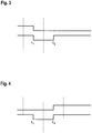
- Figure 3 shows the case when a person enters the danger zone 2 via the entrance area and then moves further in the danger zone 2 towards the robot 3.
- both OSSDs 9a, 9b change their switching state from 1 ("free protective field”) to 0 ("object present") at time t 1 . These switching states remain as long as the person is in the protective field 11b (and thus also in the protective field 11a).
- the person leaves protective field 11b, but remains in protective field 11a.
- the switching state of the OSSD 9b changes from 0 to 1 at the time t 2 , while the switching state of the OSSD 9a remains unchanged.
- the OSSDs 9a, 9b bring about a first safety function in such a way that the system, that is to say the robot 3, is shut down via the controller 10, so that there are no longer any dangers going out.
- At least one OSSD 9a, 9b always remains in the switching state 0 after the time t 1 , so that the system remains shut down from the time t 1 .
- Figure 4 shows the case when a person who is initially in the vicinity of the robot 3 moves out of the danger zone 2.
- the OSSDs 9a, 9b simultaneously change from the switching state 0 to the switching state 1 at the time t 4.
- This signal change corresponds to a person leaving the danger zone 2 regularly.
- the simultaneous change of the switching states of the OSSD 9a, 9b from 0 to 1 at the time t 4 thus forms a trigger signal for an automatic restart of the system, that is, the robot 3.
Landscapes
- Engineering & Computer Science (AREA)
- General Engineering & Computer Science (AREA)
- Mechanical Engineering (AREA)
- Alarm Systems (AREA)
- Manipulator (AREA)
Applications Claiming Priority (1)
| Application Number | Priority Date | Filing Date | Title |
|---|---|---|---|
| DE202018105474.0U DE202018105474U1 (de) | 2018-09-24 | 2018-09-24 | Vorrichtung zur Absicherung eines Gefahrenbereichs einer Anlage |
Publications (2)
| Publication Number | Publication Date |
|---|---|
| EP3627033A1 true EP3627033A1 (fr) | 2020-03-25 |
| EP3627033B1 EP3627033B1 (fr) | 2023-07-05 |
Family
ID=66647118
Family Applications (1)
| Application Number | Title | Priority Date | Filing Date |
|---|---|---|---|
| EP19176193.1A Active EP3627033B1 (fr) | 2018-09-24 | 2019-05-23 | Dispositif de sécurisation d'une zone à risque d'une installation |
Country Status (2)
| Country | Link |
|---|---|
| EP (1) | EP3627033B1 (fr) |
| DE (1) | DE202018105474U1 (fr) |
Citations (3)
| Publication number | Priority date | Publication date | Assignee | Title |
|---|---|---|---|---|
| EP1306603A2 (fr) * | 2001-10-24 | 2003-05-02 | Sick Ag | Procédé et dispositif de commande d'une fonction relative à la sécurité d'une machine |
| WO2009155948A1 (fr) * | 2008-06-26 | 2009-12-30 | Abb Ag | Système de protection de la sécurité de personnes vis-à-vis d’incidents dangereux impliquant des robots |
| DE202009012589U1 (de) * | 2009-09-16 | 2011-02-03 | Sick Ag | Optoelektronischer Sensor |
Family Cites Families (3)
| Publication number | Priority date | Publication date | Assignee | Title |
|---|---|---|---|---|
| DE10304054B4 (de) * | 2003-02-01 | 2005-03-03 | Leuze Lumiflex Gmbh + Co. Kg | Optischer Sensor |
| DE202008016093U1 (de) * | 2008-12-05 | 2010-04-15 | Sick Ag | Überwachungssensor |
| ES2678844T3 (es) * | 2015-10-09 | 2018-08-17 | Sick Ag | Dispositivo de protección optoelectrónico |
-
2018
- 2018-09-24 DE DE202018105474.0U patent/DE202018105474U1/de active Active
-
2019
- 2019-05-23 EP EP19176193.1A patent/EP3627033B1/fr active Active
Patent Citations (3)
| Publication number | Priority date | Publication date | Assignee | Title |
|---|---|---|---|---|
| EP1306603A2 (fr) * | 2001-10-24 | 2003-05-02 | Sick Ag | Procédé et dispositif de commande d'une fonction relative à la sécurité d'une machine |
| WO2009155948A1 (fr) * | 2008-06-26 | 2009-12-30 | Abb Ag | Système de protection de la sécurité de personnes vis-à-vis d’incidents dangereux impliquant des robots |
| DE202009012589U1 (de) * | 2009-09-16 | 2011-02-03 | Sick Ag | Optoelektronischer Sensor |
Also Published As
| Publication number | Publication date |
|---|---|
| DE202018105474U1 (de) | 2020-01-03 |
| EP3627033B1 (fr) | 2023-07-05 |
Similar Documents
| Publication | Publication Date | Title |
|---|---|---|
| EP3339715B1 (fr) | Système de protection d'accès | |
| EP2017524B1 (fr) | Barrière lumineuse | |
| EP2306063B1 (fr) | Capteur de sécurité | |
| DE10216122A1 (de) | Objekterfassung | |
| EP3415804B1 (fr) | Dispositif de sécurité | |
| DE19649593B4 (de) | Verriegelungseinrichtung | |
| DE102007055521A1 (de) | Vorrichtung zur Überwachung eines Überwachungsbereichs | |
| EP3627033B1 (fr) | Dispositif de sécurisation d'une zone à risque d'une installation | |
| DE3640600A1 (de) | Feuer- und explosionserfassungs- und -unterdrueckungseinrichtung | |
| EP3575666B1 (fr) | Dispositif de sécurisation d'une zone à risque d'une installation | |
| EP3767152B1 (fr) | Dispositif de fixation pour une machine et procédé de fonctionnement d'un dispositif de fixation | |
| DE3728354C2 (fr) | ||
| DE202018103933U1 (de) | Vorrichtung zur Überwachung eines Gefahrenbereichs | |
| EP2988419A1 (fr) | Procede de determination de l'etat d'un element indicateur formant un court-circuit | |
| DE102007036677A1 (de) | Sicherheitssensor | |
| EP3862617B1 (fr) | Dispositif de sécurisation d'une zone dangereuse | |
| DE3909073C2 (fr) | ||
| DE102018116264B4 (de) | Lichtgitter | |
| EP4354010A1 (fr) | Dispositif de surveillance | |
| EP4290117A1 (fr) | Dispositif de surveillance | |
| EP3869240A1 (fr) | Agencement de capteurs et procédé de fonctionnement d'un agencement de capteurs | |
| DE202022103201U1 (de) | Überwachungseinrichtung | |
| DE2609237A1 (de) | Einrichtung zur ueberwachung einer waschstrasse und zaehlung durchfahrender kraftfahrzeuge | |
| EP4307249A1 (fr) | Système de surveillance doté d'un détecteur de personnes | |
| EP3875993A1 (fr) | Dispositif capteur et procédé de fonctionnement d'un dispositif capteur |
Legal Events
| Date | Code | Title | Description |
|---|---|---|---|
| PUAI | Public reference made under article 153(3) epc to a published international application that has entered the european phase |
Free format text: ORIGINAL CODE: 0009012 |
|
| STAA | Information on the status of an ep patent application or granted ep patent |
Free format text: STATUS: THE APPLICATION HAS BEEN PUBLISHED |
|
| STAA | Information on the status of an ep patent application or granted ep patent |
Free format text: STATUS: REQUEST FOR EXAMINATION WAS MADE |
|
| AK | Designated contracting states |
Kind code of ref document: A1 Designated state(s): AL AT BE BG CH CY CZ DE DK EE ES FI FR GB GR HR HU IE IS IT LI LT LU LV MC MK MT NL NO PL PT RO RS SE SI SK SM TR |
|
| AX | Request for extension of the european patent |
Extension state: BA ME |
|
| 17P | Request for examination filed |
Effective date: 20200316 |
|
| RBV | Designated contracting states (corrected) |
Designated state(s): AL AT BE BG CH CY CZ DE DK EE ES FI FR GB GR HR HU IE IS IT LI LT LU LV MC MK MT NL NO PL PT RO RS SE SI SK SM TR |
|
| STAA | Information on the status of an ep patent application or granted ep patent |
Free format text: STATUS: EXAMINATION IS IN PROGRESS |
|
| 17Q | First examination report despatched |
Effective date: 20220530 |
|
| GRAP | Despatch of communication of intention to grant a patent |
Free format text: ORIGINAL CODE: EPIDOSNIGR1 |
|
| STAA | Information on the status of an ep patent application or granted ep patent |
Free format text: STATUS: GRANT OF PATENT IS INTENDED |
|
| INTG | Intention to grant announced |
Effective date: 20230224 |
|
| GRAS | Grant fee paid |
Free format text: ORIGINAL CODE: EPIDOSNIGR3 |
|
| RBV | Designated contracting states (corrected) |
Designated state(s): DE |
|
| GRAA | (expected) grant |
Free format text: ORIGINAL CODE: 0009210 |
|
| STAA | Information on the status of an ep patent application or granted ep patent |
Free format text: STATUS: THE PATENT HAS BEEN GRANTED |
|
| AK | Designated contracting states |
Kind code of ref document: B1 Designated state(s): DE |
|
| P01 | Opt-out of the competence of the unified patent court (upc) registered |
Effective date: 20230606 |
|
| REG | Reference to a national code |
Ref country code: DE Ref legal event code: R096 Ref document number: 502019008378 Country of ref document: DE |
|
| REG | Reference to a national code |
Ref country code: DE Ref legal event code: R097 Ref document number: 502019008378 Country of ref document: DE |
|
| PLBE | No opposition filed within time limit |
Free format text: ORIGINAL CODE: 0009261 |
|
| STAA | Information on the status of an ep patent application or granted ep patent |
Free format text: STATUS: NO OPPOSITION FILED WITHIN TIME LIMIT |