EP2017524B1 - Barrière lumineuse - Google Patents
Barrière lumineuse Download PDFInfo
- Publication number
- EP2017524B1 EP2017524B1 EP08012174.2A EP08012174A EP2017524B1 EP 2017524 B1 EP2017524 B1 EP 2017524B1 EP 08012174 A EP08012174 A EP 08012174A EP 2017524 B1 EP2017524 B1 EP 2017524B1
- Authority
- EP
- European Patent Office
- Prior art keywords
- safety
- phase
- light grid
- critical object
- critical
- Prior art date
- Legal status (The legal status is an assumption and is not a legal conclusion. Google has not performed a legal analysis and makes no representation as to the accuracy of the status listed.)
- Expired - Fee Related
Links
- 238000011156 evaluation Methods 0.000 claims description 38
- 238000001514 detection method Methods 0.000 claims description 19
- 230000002123 temporal effect Effects 0.000 claims description 2
- 230000003247 decreasing effect Effects 0.000 claims 1
- 238000012544 monitoring process Methods 0.000 description 64
- 230000006870 function Effects 0.000 description 18
- 230000001681 protective effect Effects 0.000 description 9
- 230000004888 barrier function Effects 0.000 description 6
- 238000000034 method Methods 0.000 description 5
- 230000002028 premature Effects 0.000 description 4
- 230000007423 decrease Effects 0.000 description 2
- 229910000831 Steel Inorganic materials 0.000 description 1
- 238000013459 approach Methods 0.000 description 1
- 230000005540 biological transmission Effects 0.000 description 1
- 230000000903 blocking effect Effects 0.000 description 1
- 238000000151 deposition Methods 0.000 description 1
- 238000013461 design Methods 0.000 description 1
- 238000011161 development Methods 0.000 description 1
- 230000018109 developmental process Effects 0.000 description 1
- 238000010586 diagram Methods 0.000 description 1
- 231100001261 hazardous Toxicity 0.000 description 1
- 230000000149 penetrating effect Effects 0.000 description 1
- 230000035515 penetration Effects 0.000 description 1
- 239000007787 solid Substances 0.000 description 1
- 239000010959 steel Substances 0.000 description 1
Images


Classifications
-
- F—MECHANICAL ENGINEERING; LIGHTING; HEATING; WEAPONS; BLASTING
- F16—ENGINEERING ELEMENTS AND UNITS; GENERAL MEASURES FOR PRODUCING AND MAINTAINING EFFECTIVE FUNCTIONING OF MACHINES OR INSTALLATIONS; THERMAL INSULATION IN GENERAL
- F16P—SAFETY DEVICES IN GENERAL; SAFETY DEVICES FOR PRESSES
- F16P3/00—Safety devices acting in conjunction with the control or operation of a machine; Control arrangements requiring the simultaneous use of two or more parts of the body
- F16P3/12—Safety devices acting in conjunction with the control or operation of a machine; Control arrangements requiring the simultaneous use of two or more parts of the body with means, e.g. feelers, which in case of the presence of a body part of a person in or near the danger zone influence the control or operation of the machine
- F16P3/14—Safety devices acting in conjunction with the control or operation of a machine; Control arrangements requiring the simultaneous use of two or more parts of the body with means, e.g. feelers, which in case of the presence of a body part of a person in or near the danger zone influence the control or operation of the machine the means being photocells or other devices sensitive without mechanical contact
- F16P3/144—Safety devices acting in conjunction with the control or operation of a machine; Control arrangements requiring the simultaneous use of two or more parts of the body with means, e.g. feelers, which in case of the presence of a body part of a person in or near the danger zone influence the control or operation of the machine the means being photocells or other devices sensitive without mechanical contact using light grids
-
- G—PHYSICS
- G01—MEASURING; TESTING
- G01V—GEOPHYSICS; GRAVITATIONAL MEASUREMENTS; DETECTING MASSES OR OBJECTS; TAGS
- G01V8/00—Prospecting or detecting by optical means
- G01V8/10—Detecting, e.g. by using light barriers
- G01V8/20—Detecting, e.g. by using light barriers using multiple transmitters or receivers
Definitions
- the invention relates to a light grid according to the preamble of claim 1.
- Such light grids are used, in particular, in the field of personal protection, with these being used as a monitoring area to monitor a danger area on work equipment formed by a machine.
- a light grid used for such monitoring tasks is from the DE 299 20 715 U1 known.
- the light grid comprises a multiple arrangement of light barriers. If an object or a person is detected with this light grid, an object message is generated in the light grid, which leads to the machine being switched off.
- the light curtain fulfills its safety function, which it detects when a person enters the danger zone.
- penetration of a workpiece to be machined with the machine into the danger zone would also lead to an object message in the light grid, which would then result in the machine being switched off. Since the workpiece to be machined is a non-safety-critical object, switching off the machine when it is detected within the danger zone is unnecessary and therefore undesirable.
- the light curtains are the DE 299 20 715 U1
- so-called muting sensors are provided at the entrance or exit of the danger zone, which enable a distinction to be made between people or generally safety-critical objects and permissible objects as non-safety-critical objects. If a permissible object is detected, the muting sensors generate a muting signal, that is, a Bridging signal, which means that despite an interruption in the light barriers of the light curtain, the switch-off function is temporarily deactivated, i.e. the machine is not switched off. If, however, one of the light barriers is interrupted and the muting sensors do not generate a bypass signal, the machine to be monitored is switched off.
- the disadvantage here is that the muting sensors formed by reflection light barriers, as additional sensors to the light curtain, require a considerable amount of design and thus also cause a considerable increase in the cost of implementing the danger zone protection. This disadvantage is exacerbated by the fact that a pair of muting sensors must be provided at both the input and the output so that the permissible objects can be distinguished from non-permissible objects.
- the EP 1 353 196 A1 relates to a method for the detection of two or more moving objects in a monitoring area, wherein a horizontal light grid with a plurality of mutually parallel light barriers is used.
- the specification of an entry area for the objects, the size of the objects as well as the distance between the objects are monitored in combination. If at least one of these three criteria is not met, a control signal is issued and, for example, the system is shut down.
- the invention also relates to a light grid for performing this method.
- the US 5,243,183 A. relates to a light grid with a series arrangement of light-emitting transmitters and a series arrangement of light beams receiving receivers for monitoring a protective field. If the protective field is clear, the light beams emitted by the transmitters reach unassigned receivers. Object detection takes place in that in a Evaluation unit beam interruptions of one or more light beams are registered. In this object detection, a distinction is made between permissible and impermissible objects.
- the DE 10 2005 030 829 A1 relates to a method for operating a light grid with different method steps and light grid with a transmitting and receiving unit. Sending out a plurality of light beams spaced linearly next to one another and running parallel to one another by means of the linearly extending transmitting unit and receiving these light beams with the receiving unit extending parallel to the transmitting unit.
- a protective field is thus defined between the transmitting and receiving unit.
- the protective field is arranged at an angle to a direction of movement of objects penetrating the protective field, the angle being between 45 ° and 135 °, except 90 °, so that the light beams are sequentially interrupted one after the other by the object. On the basis of this sequential interruption, the speed of the object is determined and at least an extent of at least one part of the object protruding in the direction of movement. The detected extent is compared with previously stored reference values and a switching signal is generated depending on the comparison result.
- the DE 295 00 873 U1 relates to a light grid with a number of light transmitters and associated light receivers, by means of which a protective field is scanned cyclically.
- the light transmitters are switched on at predetermined times for a certain period of time. At certain times, light is expected from a light transmitter at least on a light receiver.
- the interruption of a light beam caused by an object in the protective field and the absence of an electrical output signal at this light receiver means that a warning or alarm signal can be derived.
- the absence of light is not used to trigger a warning or shutdown signal.
- the invention has for its object to provide a sensor-monitored danger zone monitoring, with which safe monitoring of a danger zone on a work tool can be carried out with as little effort as possible, without unnecessarily restricting the availability of the work tool.
- the light curtain according to the invention is used to detect objects in a monitoring area and comprises a number of beam axes, each of which is formed by a transmitter emitting light beams and an assigned receiver.
- the longitudinal axis of the light grid is inclined at an angle to the vertical.
- the beam axes are not interrupted when the monitoring area is clear, and at least one beam axis is interrupted in the monitoring area when an object interferes.
- the light grid comprises an evaluation unit, by means of which a safety-critical one penetrates An object message can be generated in the monitoring area.
- a non-safety-critical object can be identified in the evaluation unit when it passes through the monitoring area in that the beam axes interrupted by the non-safety-critical object are registered as different muting phases during at least one running-in phase and one run-through phase and a check is carried out on the basis of these to determine whether specific run-in and run-through phases Object characteristics of the non-safety-critical object stored in the evaluation unit are fulfilled.
- the run-in phase the front edge of the non-safety-critical object runs into the monitoring area and the entire height of the non-safety-critical object is detected during the run-through phase. If an object that is not critical to safety is identified, a muting signal is generated in the evaluation unit. By detecting the non-safety-critical object, the muting signal is switched off in a time-resolved manner in the individual muting phases.
- a monitoring function is thus implemented such that an object message is generated when a safety-critical object is detected in the monitoring area.
- the light curtain designed in this way can thus be used in particular in safety-related applications, in particular in the field of personal protection, the light curtain being designed for this purpose as a safety sensor which, in terms of its structure, meets the relevant safety standards.
- the light grid is generally used to monitor a danger zone of a work equipment such as a machine or system.
- An object detection signal is generated with the light grid, which is used to control the work equipment. If a free monitoring area is registered by means of the light grid and a corresponding object detection signal is generated, the work equipment is activated by this object detection signal, that is to say put into operation. If a safety-critical object is registered in the monitored area by means of the light grid, an object message is generated as the object detection signal, which is used to switch off the Work equipment leads to avoid danger to people in the danger area.
- a major advantage of the light grid according to the invention is that muting can be carried out with this as an additional function.
- non-safety-critical objects With the light curtain itself, that is to say without additional muting sensors, non-safety-critical objects can be identified whose intrusion into the monitoring area and thus into the hazardous area of the work equipment is not critical, that is to say is not a safety hazard.
- a muting signal is generated by means of the light grid.
- This muting signal represents a bridging signal in such a way that the light grid is muted, so that during the activated muting, an object intervention in the monitoring area does not lead to the generation of an object message and thus not to the stopping of the work equipment.
- the detection of a non-safety-critical object takes place during its passage through the monitoring area in different muting phases, namely a running-in phase in which the front edge of the non-safety-critical object runs into the monitoring area, a passage phase in which the entire height of the non-safety-critical object is detected by the light grid , and advantageously also in a phase-out phase in which the rear edge runs out of the monitoring area.
- the detection of the respective non-safety-critical object takes place in that specific object features which characterize the non-safety-critical object are stored in the evaluation unit for the individual muting phases.
- the beam axes of the light grid interrupted by the non-safety-critical object are continuously recorded and evaluated in such a way that it is checked whether the object features are fulfilled in the individual muting phases, that is, at the detected object.
- Another important advantage of this evaluation is that not only a non-safety-critical object is recognized as such, that is to say on the basis of its geometry, but also its speed and movement device can be detected and thus also controlled.
- the muting can be canceled, that is to say the muting signal is switched off, in a correspondingly time-resolved manner by detecting the non-safety-critical object in the individual muting phases.
- muting can already be canceled if the non-safety-critical object is not recognized in the first muting phase, that is, the running-in phase.
- the muting signal can only be canceled if the non-safety-critical object has not been recognized in all muting phases.
- muting is ended prematurely, i.e. the muting signal is withdrawn and the light curtain is reactivated if, when passing through the non-safety-critical object, it is determined on the basis of the registered mother of the interrupted beam axes of the light curtain that the object features are in at least one of the muting phases For the non-safety-critical objects are no longer recognized. In the event of such a deviation, an error signal is generated in the evaluation unit, by means of which the muting signal is canceled. Hazards can thus be uncovered in such a way that, in addition to the non-security-critical object, a further, possibly security-critical object passes the monitoring area. To avoid endangering people, the light curtain is activated by canceling the muting signal, which then generates an object message and thus stops the work equipment.
- the work equipment of the non-safety-critical object is still in the monitoring area.
- the conveyor line that moves the non-safety-critical object is then also shut down.
- the free travel function i.e. the override.
- an operator manually cancels the monitoring function of the light grid so that the non-safety-critical object can move out of the monitoring area.
- the operator himself has to check that no safety-critical object, in particular no person, enters the monitoring area. After the non-safety-critical object leaves the light curtain, the light curtain is reactivated.
- Figure 1 shows schematically the structure of a light grid 1, which is used to detect objects in a monitoring area.
- the light grid 1 comprises an arrangement of transmitters 3 emitting light beams 2, which are activated cyclically one after the other using a control unit 4.
- the transmitter 3 and the control unit 4 are integrated in a first housing 5.
- the light grid 1 further comprises an arrangement of receivers 6 for receiving the transmitted light beams 2.
- the receivers 6 are assigned an evaluation unit 7 for controlling the receiver operation and for evaluating the reception signals present at the outputs.
- the receiver 6 and the evaluation unit 7 are integrated in a second housing 8.
- the transmitted light beams 2 are guided through windows, not shown, in the front walls of the housing 5. How out Figure 1 can be seen, the transmitter 3 and the receiver 6 are arranged in separate housings 5 on opposite edges of the monitoring area. In this case, each transmitter 3 is assigned a receiver 6, so that when the monitoring area is clear, the transmitted light beams 2 emitted by the transmitter 3 strike the receiver 6 as received light beams.
- a transmitter 3 and the associated receiver 6 each define a beam axis of the light grid 1, the direction of the beam axis being given by the transmitted light beams 2 of the respective transmitter 3.
- the beam axes of the light grid 1 lying in one plane form the monitoring area. If an object interferes in the monitoring area, the beam path of the transmitted light beams 2 of at least one transmitter 3, that is to say at least one beam axis, is interrupted.
- the transmitters 3 and receivers 6 can also be integrated in a common housing 5 which is arranged on an edge of the monitoring area.
- a reflector is then arranged on the opposite edge of the monitoring area, the transmitted light beams 2 emitted by the transmitters 3 being reflected on the reflector in the case of a free monitoring area and being guided from there to the receiver 6.
- a binary switching signal is generated in the evaluation unit 7 as the object detection signal, the switching states of which indicate whether an object is in the monitoring area or not.
- the switching signal assumes the "free monitoring area” switching state if none of the transmitted light beams 2 are interrupted. If, on the other hand, at least the transmission light beams 2 of a transmitter 3 are interrupted, the switching signal assumes the switching state "object recognized", that is, there is an object intervention in the monitoring area.
- the light grid 1 is preferably used in the field of personal protection.
- the evaluation unit 7 has a redundant, two-channel structure.
- the evaluation unit 7 preferably has two mutually cyclically monitoring computer units.
- the light grid 1 can then be used as a monitoring area to monitor the danger area on a work equipment such as a machine for the purpose of personal protection. Doing so the work equipment is switched off as soon as an object intervention in the monitoring area is registered by means of the light grid 1, ie an object message generated in the light grid 1 leads to the work equipment being stopped.
- the light grid 1 is used to generate an object message which leads to the work equipment being switched off only if the object detected in the monitoring area is a safety-critical object.
- An intrusion of a non-safety-critical object in the monitoring area does not result in the work equipment being switched off.
- the light grid 1 is equipped with a muting function. This muting function provides that when a non-safety-critical object is detected in the monitoring area, a muting signal is generated which mutes the light curtain 1, that is to say it is deactivated in such a way that the generation of an object message which would lead to the work equipment being switched off is suppressed.
- This muting function is always active and is generally canceled, i.e. switched off, if the non-safety-critical object is not recognized.
- the non-safety-critical object is detected during the passage through the monitoring area by registering the beam axes that are interrupted thereby.
- the detection of the non-safety-critical object is carried out separately in several muting phases, namely during a run-in phase, during which the front edge of the non-safety-critical object enters the monitoring area of the light curtain 1, during a through-phase, during which the non-safety-critical object is completely detected in its entire height is, and preferably also during a phase-out phase, within which the rear edge of the non-safety-critical object runs out of the monitoring area.
- the beam patterns of the interrupted beam axes are used to examine whether specific object features, which are defined for the individual muting phases, characterize the non-safety-critical object which are stored separately in the evaluation unit 7 for the individual muting phases are fulfilled.
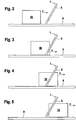
- FIGS Figures 2 to 5 , Figure 6 shows the temporal course of the pattern of the beam axes of the light grid 1 interrupted by the non-safety-critical object. There, a danger area in the area of a conveyor path 9 is monitored with a light grid 1.
- the level of the monitoring area of the light grid 1 runs perpendicular to the target level in the Figures 2 to 5 ,
- the housing 8 of the light grid 1 is not aligned in the vertical direction. Rather, the longitudinal axes of the housing 8 are inclined at an angle to the vertical.
- rolls 10, preferably paper rolls on which paper webs are rolled up are conveyed at a speed V in the horizontal direction on the conveyor line 9.
- the transmitted light beams 2 of the light grid 1 scan the outer surface of the roller 10. In the projection, this forms a surface with a rectangular outer contour perpendicular to the plane of the beam axes, as in the Figures 2 to 5 shown.
- the light curtain 1 is inclined in the direction of travel of the paper roll.
- the light grid 1 can also be inclined against the direction of travel of the paper roll.
- Figure 2 shows the light curtain 1 with a free monitoring area and with the roller 10 which is at a distance from the light curtain 1, that is to say has not yet entered the monitoring area.
- Figure 3 shows the roll 10 in the run-in phase in the monitoring area.
- the first lowermost beam axis of the light grid 1 is first interrupted. Based on this, an increasing number of interrupted beam axes is registered during the run-in phase until the roll 10 is recorded in its entire height in the run-through phase ( Figure 4 ).
- Figure 5 shows the number of interrupted beam axes steadily in the phase of the roll 10 ( Figure 5 ), with the lowest beam axis of the light curtain 1 being cleared first, then the second and so on until finally the roller 10 has moved out of the monitoring area. If the light curtain 1 was inclined against the direction of travel of the paper roll, the upper edge of the paper roll would first be detected by the light curtain in the running-in phase.
- the time course of the interrupted beam axes obtained in this way is shown in Figure 6 shown, the hatched area forming the area of the interrupted beam axes.
- roller 10 has not yet entered the monitoring area.
- the running-in phase is in Figure 6 marked with I.
- the roll 10 is detected in its entire object height, so that a total of n 0 of the total N beam axes of the light grid 1 are interrupted.
- the steady, that is to say seamless increase in the interrupted beam axes from 1 to n 0 is stored in the evaluation unit 7 as an object feature for the running-in phase.
- the throughput time T E can be specified, within which, starting from the interruption of the first beam axis, all n 0 beam axes of the light grid 1 corresponding to the object height are interrupted.
- Figure 6 the case of an error-free detection of the front flank of the roller 10 is shown, since in the running-in phase the number of interrupted beam axes increases continuously from 1 to n 0 and this takes place in a time interval t 1 - t 0 , which within the tolerance limits specified in the evaluation unit 7 the specified throughput time T E corresponds.
- a certain jitter can be allowed for the steady increase of the interrupted beam axes in the running-in phase.
- the position of the lower edge of the roll 10 can also be detected during the running-in phase. If the light curtain 1 were inclined against the direction of travel, the position of the upper edge of the roller 10 could be monitored during the running-in phase.
- the roll 10 is recognized in its entire height.
- the setpoint n s of the interrupted steel axes is specified in the evaluation unit 7 for specifying the setpoint height.
- Figure 6 again shows the error-free case in which the required object height is recognized, that is to say the number of interrupted beam axes n 0 registered in the throughput phase corresponds exactly to the target value n s .
- tolerance limits ⁇ n can be specified, so that the criterion for the detection of the non-safety-critical object is that the current registered number of interrupted beam axes within the interval [n s - ⁇ n , n s + ⁇ n]. This condition must be met during the entire throughput phase.
- the throughput time T D required for the throughput phase can be stored in the evaluation unit 7 as a further object feature. Then the measured throughput time t 2 - t 1 must match the target value T D within predetermined tolerance limits so that the non-safety-critical object is considered to be recognized.
- roller 10 is a solid object, an uninterrupted sequence of beam axes must always be interrupted by this during the through phase, which is monitored in the evaluation unit 7.
- the light curtain 1 is muted by a muting signal generated in the evaluation unit 7 it means that no object message is generated which would lead to a shutdown of the work equipment, in the present case the conveyor line 9 and a machine, not shown, assigned to it.
- the muting can be canceled when the non-safety-critical object has been recognized in all three muting phases. Furthermore, muting can also be canceled in the run-in phase or only in the run-through phase.
- Muting is generally abolished if the object features describing the geometry of the non-safety-critical object do not meet and, if additionally defined in the evaluation unit 7, the specified throughput times in the muting phases are not observed.
- the direction of movement of a non-safety-critical object can also be monitored. How out Figure 3 can be seen in one of the left in the Monitoring area immersing non-safety-critical object first interrupted the lowest beam axis of the light curtain 1. If the light grid 1 approaches the light grid 1 from the right, the uppermost beam axis n 0 is first interrupted when the non-safety-critical object is immersed in the monitoring area.
- the function of the premature muting end provides that an error signal is generated when a muting signal is generated by the entry of a non-safety-critical object into the monitoring area if a deviation from stored object features is registered in the evaluation unit 7 by evaluating the interrupted beam axes while passing through the non-safety-critical object becomes.
- the muting signal is canceled by the error signal, ie the light curtain 1 is activated.
- the system with the conveyor line 9 is stopped. However, this means that the non-safety-critical object can no longer be extended.
- the free travel function the so-called override.
- an operator can manually deactivate the light curtain 1 in order to move the non-safety-critical object out of the monitoring area. Since the security function of the light curtain 1 is temporarily deactivated, the operator must ensure that no one enters the monitoring area.
- the inclination of the light grid 1 in the arrangement according to the Figures 2 to 5 can be varied. In principle, a vertical position of the housing 5, 8 of the light grid 1 is even possible. In this case, however, the leading and trailing edges can be used during the running-in and running-out phases of the non-safety-critical object can no longer be detected by a continuously increasing or falling number of interrupted beam axes. In this case, the running in of the leading and trailing edges can only be checked by monitoring the throughput time in combination with the criterion that only a maximum number of beam axes may be interrupted without gaps.
Claims (17)
- Barrière lumineuse pour la détection d'objets dans une zone de surveillance, comportant un certain nombre d'axes de faisceaux formés chacun par un émetteur (3) émettant des faisceaux lumineux transmis (2) et un récepteur (6) associé, l'axe longitudinal de la barrière lumineuse étant incliné d'un angle d'inclinaison par rapport à la verticale, les axes de faisceaux n'étant pas interrompus lorsque la zone de surveillance est libre, et au moins un axe de faisceau étant interrompu dans la zone de surveillance en cas d'intrusion d'un objet, et comportant une unité d'évaluation au moyen de laquelle un message d'objet peut être généré si un objet critique pour la sécurité pénètre dans la zone de surveillance, caractérisé en ce qu'un objet non critique pour la sécurité peut être identifié dans l'unité d'évaluation (7) lorsqu'il traverse la zone de surveillance, pendant au moins une phase d'entrée et une phase de passage, les axes du faisceau interrompu par l'objet non critique pour la sécurité sont enregistrés comme différentes phases de mise en sourdine et, à l'aide de ces éléments, le système vérifie si les caractéristiques spécifiques de l'objet non critique pour la sécurité qui sont enregistrées dans l'unité d'évaluation (7) et spécifiques pour la phase d'entrée et la phase de passage sont remplies, le bord avant de l'objet non critique pour la sécurité pénétrant dans la zone de surveillance pendant la phase d'entrée et la hauteur totale de l'objet non critique pour la sécurité étant détectés pendant la phase de passage, en ce qu'un signal de mise en sourdine est généré dans l'unité d'évaluation (7) pour un objet non critique identifié et que le signal de mise en sourdine est coupé dans un délai déterminé par la détection de l'objet non critique pour la sécurité pendant les phases de mise en sourdine individuelles.
- Barrière lumineuse selon la revendication 1, caractérisée en ce que l'objet non critique pour la sécurité est en outre détecté pendant une phase de sortie progressive comme troisième phase de mise en sourdine, le bord arrière de l'objet non critique pour la sécurité quittant la zone de surveillance pendant la phase de sortie progressive, et les caractéristiques spécifiques de l'objet pour cette phase de sortie progressive étant enregistrées dans l'unité d'évaluation (7).
- Barrière lumineuse selon la revendication 1, caractérisée en ce que le bord avant de l'objet non critique pour la sécurité peut être détecté par un nombre sans cesse croissant d'axes de faisceau interrompus.
- Barrière lumineuse selon la revendication 3, caractérisée en ce que pendant la phase d'entrée, la position du bord supérieur ou inférieur de l'objet non critique pour la sécurité est également surveillée.
- Barrière lumineuse selon l'une des revendications 1 à 4, caractérisée en ce que le bord de fuite de l'objet non critique pour la sécurité peut être détecté par un nombre décroissant continu d'axes de faisceau interrompus.
- Barrière lumineuse selon la revendication 5, caractérisé en ce que pendant la phase de sortie, la position du bord supérieur ou inférieur de l'objet non critique pour la sécurité est également surveillée.
- Barrière lumineuse selon l'une des revendications 1 à 6, caractérisée en ce que pendant la phase d'entrée et/ou de sortie, la hauteur de l'objet non critique pour la sécurité est contrôlée par un système de surveillance dans l'unité d'évaluation (7) afin que le nombre d'axes de faisceau interrompus ne dépasse pas une valeur maximale.
- Barrière lumineuse selon l'une des revendications 1 à 7, caractérisée en ce que l'objet non critique pour la sécurité est détecté par ladite barrière lumineuse pendant la phase de passage sur toute sa hauteur, cette hauteur étant surveillée dans l'unité d'évaluation (7) sur la base du nombre d'axes de faisceau interrompus, le nombre d'axes de faisceau interrompus étant comparé comme valeurs mesurées à une valeur souhaitée et la hauteur de l'objet non critique étant considérée comme reconnue lorsque les valeurs de mesure enregistrées correspondent à la valeur souhaitée dans des limites de tolérance prédéterminées.
- Barrière lumineuse selon la revendication 8, caractérisée en ce que, pendant la phase de passage, le système surveille en outre s'il y a une séquence complète d'axes de faisceau interrompus à travers l'objet non critique pour la sécurité et en ce que, pendant la phase de passage, la position du bord supérieur et/ou inférieur de l'objet non critique pour la sécurité est également surveillée dans l'unité d'évaluation (7).
- Barrière lumineuse selon l'une des revendications 1 à 9, caractérisée en ce que la vitesse de l'objet non critique pour la sécurité est surveillée dans au moins une des phases de mise en sourdine, un temps de passage de l'objet non critique pour la sécurité étant enregistré comme valeur souhaitée dans l'unité d'évaluation (7) à cet effet.
- Barrière lumineuse selon l'une des revendications 1 à 10, caractérisée en ce que la direction de déplacement de l'objet non critique pour la sécurité peut être déterminée à partir de la trajectoire temporelle des axes de faisceau interrompus dans la phase d'entrée et/ou de sortie.
- Barrière lumineuse selon l'une des revendications 1 à 11, caractérisée en ce qu'elle peut être mise en sourdine par le signal d'inhibition de sorte que le message d'objet est supprimé lors de la détection d'objet et que le signal d'inhibition est désactivé si un objet non critique pour la sécurité n'est pas détecté dans au moins une des phases de mise en sourdine.
- Barrière lumineuse selon la revendication 12, caractérisée en ce qu'un signal d'erreur est généré dans l'unité d'évaluation (7) lorsqu'un écart par rapport aux caractéristiques de l'objet mémorisé est enregistré pendant la détection d'un objet non critique pour la sécurité pendant une phase de mise en sourdine, qui annule le signal de mise en sourdine.
- Barrière lumineuse selon la revendication 13, caractérisée en ce qu'elle peut être désactivée manuellement lorsque le signal de mise en sourdine est annulé afin de retirer un objet non critique pour la sécurité situé dans la zone de surveillance.
- Barrière lumineuse selon l'une des revendications 1 à 14, caractérisée en ce qu'elle est constituée d'un capteur de sécurité au moyen duquel une zone dangereuse est surveillée sur des instruments de travail.
- Barrière lumineuse selon la revendication 15, caractérisée en ce que les instruments de travail sont désactivés par un message objet.
- Barrière lumineuse selon l'une des revendications 1 à 16, caractérisé en ce que l'unité d'évaluation (7) présente une structure redondante avec deux unités informatiques se contrôlant de manière cyclique du côté entrée.
Applications Claiming Priority (1)
| Application Number | Priority Date | Filing Date | Title |
|---|---|---|---|
| DE102007033766A DE102007033766B4 (de) | 2007-07-18 | 2007-07-18 | Lichtgitter |
Publications (3)
| Publication Number | Publication Date |
|---|---|
| EP2017524A2 EP2017524A2 (fr) | 2009-01-21 |
| EP2017524A3 EP2017524A3 (fr) | 2015-12-30 |
| EP2017524B1 true EP2017524B1 (fr) | 2019-12-25 |
Family
ID=40149005
Family Applications (1)
| Application Number | Title | Priority Date | Filing Date |
|---|---|---|---|
| EP08012174.2A Expired - Fee Related EP2017524B1 (fr) | 2007-07-18 | 2008-07-05 | Barrière lumineuse |
Country Status (2)
| Country | Link |
|---|---|
| EP (1) | EP2017524B1 (fr) |
| DE (1) | DE102007033766B4 (fr) |
Families Citing this family (13)
| Publication number | Priority date | Publication date | Assignee | Title |
|---|---|---|---|---|
| DE102009048111B4 (de) * | 2009-10-02 | 2020-04-16 | Leuze Electronic Gmbh + Co. Kg | Sicherheitssensor |
| JP5229310B2 (ja) | 2010-12-17 | 2013-07-03 | オムロン株式会社 | 多光軸光電センサ |
| JP6291993B2 (ja) | 2014-04-18 | 2018-03-14 | オムロン株式会社 | 多光軸光電センサ |
| US9910186B2 (en) | 2015-08-17 | 2018-03-06 | Rockwell Automation Safety Ag | Dynamic light curtain muting system and method |
| DE102016116828B4 (de) * | 2016-09-08 | 2021-05-06 | Sick Ag | Sicherheitslichtvorhang |
| DE202018103933U1 (de) | 2018-07-10 | 2018-07-16 | Leuze Electronic Gmbh + Co. Kg | Vorrichtung zur Überwachung eines Gefahrenbereichs |
| EP3633413B1 (fr) * | 2018-10-02 | 2024-04-17 | Leuze electronic GmbH + Co. KG | Dispositif de sécurité |
| DE202019103376U1 (de) * | 2019-06-17 | 2020-09-23 | Leuze Electronic Gmbh + Co. Kg | Vorrichtung |
| EP3770481A1 (fr) * | 2019-07-24 | 2021-01-27 | Leuze electronic GmbH + Co. KG | Dispositif capteur et procédés de surveillance de zone dangereuse |
| DE102019127373A1 (de) * | 2019-10-10 | 2021-04-15 | Dücker conveyor systems GmbH | Sicherheitsvorrichtung zur Sicherung einer Gefahrenstelle, Verfahren zur Steuerung einer Sicherheitsvorrichtung, Computerprogrammprodukt und computerlesbares Aufzeichnungsmedium |
| EP3875993B1 (fr) * | 2020-03-04 | 2023-10-25 | Leuze electronic GmbH + Co. KG | Dispositif capteur et procédé de fonctionnement d'un dispositif capteur |
| DE202020101618U1 (de) | 2020-03-26 | 2021-06-29 | Sick Ag | System mit einem Lichtgitter zur Erfassung von bewegten Objekten in einem Schutzfeld |
| EP3974699A1 (fr) | 2020-09-24 | 2022-03-30 | Leuze electronic GmbH + Co. KG | Dispositif de surveillance |
Citations (1)
| Publication number | Priority date | Publication date | Assignee | Title |
|---|---|---|---|---|
| EP1353196A1 (fr) * | 2002-04-12 | 2003-10-15 | Sick Ag | Détection d'un objet et barrière optique |
Family Cites Families (10)
| Publication number | Priority date | Publication date | Assignee | Title |
|---|---|---|---|---|
| US5243183A (en) * | 1992-09-15 | 1993-09-07 | Triad Controls, Inc. | Obstruction position detecting system with comparison and memory means |
| DE4305559A1 (de) * | 1993-02-24 | 1994-08-25 | Hans Schiesl | Anordnung und Verfahren zur Konturerkennung von Gegenständen |
| DE4424537A1 (de) * | 1994-07-12 | 1996-01-18 | Sick Optik Elektronik Erwin | Verfahren zum Betrieb eines Lichtgitters und Lichtgitter |
| GB2309552B (en) * | 1996-01-25 | 2000-01-19 | Rwl Consultants Ltd | Failsafe system monitoring |
| DE19946476A1 (de) * | 1999-09-28 | 2001-03-29 | Sick Ag | Verfahren und Vorrichtung zum Überwachen eines Schutzbereichs |
| DE29920715U1 (de) | 1999-11-25 | 2000-02-24 | Leuze Lumiflex Gmbh & Co | Lichtschrankenanordnung zur Überwachung eines Gefahrenbereiches einer Maschine |
| DE20103828U1 (de) * | 2001-03-06 | 2001-06-13 | Fiessler Elektronik Ohg | Sicherheitseinrichtung zur Überwachung eines Durchgangs |
| DE102004011781A1 (de) * | 2004-03-09 | 2005-10-06 | Gerd Reime | Einrichtung zur Vereinzelung von Körpern |
| DE102005030829C5 (de) * | 2005-07-01 | 2016-05-19 | Sick Ag | Verfahren zum Betrieb eines Lichtgitters und Lichtgitter |
| ITBO20050700A1 (it) * | 2005-11-18 | 2007-05-19 | Datasensor Spa | Sistema e metodo per il controllo automatico della disattivazione temporanea di una barriera fotoelettrica |
-
2007
- 2007-07-18 DE DE102007033766A patent/DE102007033766B4/de not_active Expired - Fee Related
-
2008
- 2008-07-05 EP EP08012174.2A patent/EP2017524B1/fr not_active Expired - Fee Related
Patent Citations (1)
| Publication number | Priority date | Publication date | Assignee | Title |
|---|---|---|---|---|
| EP1353196A1 (fr) * | 2002-04-12 | 2003-10-15 | Sick Ag | Détection d'un objet et barrière optique |
Also Published As
| Publication number | Publication date |
|---|---|
| DE102007033766A1 (de) | 2009-01-22 |
| DE102007033766B4 (de) | 2009-11-26 |
| EP2017524A2 (fr) | 2009-01-21 |
| EP2017524A3 (fr) | 2015-12-30 |
Similar Documents
| Publication | Publication Date | Title |
|---|---|---|
| EP2017524B1 (fr) | Barrière lumineuse | |
| EP1353196B1 (fr) | Détection d'un objet et barrière optique | |
| EP1089030B1 (fr) | Procédé et dispositif de contrôle d'une zone de protection | |
| DE102005030829C5 (de) | Verfahren zum Betrieb eines Lichtgitters und Lichtgitter | |
| EP3339715B1 (fr) | Système de protection d'accès | |
| EP2306063B2 (fr) | Capteur de sécurité | |
| EP1873442B1 (fr) | Méthode et dispositif pour effectuer la surveillance de la sécurité d'un passage | |
| DE102010017398B3 (de) | Verfahren zum Betrieb eines Tores sowie Vorrichtung zum Betrieb eines Tores | |
| DE102017112419B3 (de) | Zugangsabsicherungssystem | |
| EP2037297B1 (fr) | Détection d'objet et barrière lumineuse | |
| DE102008004941A1 (de) | Sicherheitsanordnung und Verfahren | |
| EP3885635B1 (fr) | Dispositif de surveillance permettant de sécuriser l'accès à une zone dangereuse à l'aide d'un capteur de sécurité | |
| EP3910230A1 (fr) | Dispositif de surveillance | |
| DE102018125736A1 (de) | Verfahren zum Schutz von Menschen in einer Umgebung einer beweglichen Maschine | |
| EP3415804B1 (fr) | Dispositif de sécurité | |
| DE202017103399U1 (de) | Zugangsabsicherungssystem | |
| EP3767152B1 (fr) | Dispositif de fixation pour une machine et procédé de fonctionnement d'un dispositif de fixation | |
| EP3754243B1 (fr) | Dispositif de sécurisation d'une zone dangereuse | |
| DE102009031226B4 (de) | Sicherheitslichtgitter | |
| EP3875993B1 (fr) | Dispositif capteur et procédé de fonctionnement d'un dispositif capteur | |
| EP3910227B1 (fr) | Dispositif de surveillance et procédé de fonctionnement d'un dispositif de surveillance | |
| EP3486545B1 (fr) | Commande de sécurité et système de sécurité | |
| DE102018116264B4 (de) | Lichtgitter | |
| EP4354010A1 (fr) | Dispositif de surveillance | |
| EP3627033A1 (fr) | Dispositif de sécurisation d'une zone à risque d'une installation |
Legal Events
| Date | Code | Title | Description |
|---|---|---|---|
| PUAI | Public reference made under article 153(3) epc to a published international application that has entered the european phase |
Free format text: ORIGINAL CODE: 0009012 |
|
| AK | Designated contracting states |
Kind code of ref document: A2 Designated state(s): AT BE BG CH CY CZ DE DK EE ES FI FR GB GR HR HU IE IS IT LI LT LU LV MC MT NL NO PL PT RO SE SI SK TR |
|
| AX | Request for extension of the european patent |
Extension state: AL BA MK RS |
|
| RIC1 | Information provided on ipc code assigned before grant |
Ipc: G01V 8/00 20060101AFI20101125BHEP |
|
| PUAL | Search report despatched |
Free format text: ORIGINAL CODE: 0009013 |
|
| AK | Designated contracting states |
Kind code of ref document: A3 Designated state(s): AT BE BG CH CY CZ DE DK EE ES FI FR GB GR HR HU IE IS IT LI LT LU LV MC MT NL NO PL PT RO SE SI SK TR |
|
| AX | Request for extension of the european patent |
Extension state: AL BA MK RS |
|
| RIC1 | Information provided on ipc code assigned before grant |
Ipc: G01V 8/00 20060101AFI20151120BHEP |
|
| 17P | Request for examination filed |
Effective date: 20151222 |
|
| RBV | Designated contracting states (corrected) |
Designated state(s): AT BE BG CH CY CZ DE DK EE ES FI FR GB GR HR HU IE IS IT LI LT LU LV MC MT NL NO PL PT RO SE SI SK TR |
|
| AKX | Designation fees paid |
Designated state(s): DE IT |
|
| AXX | Extension fees paid |
Extension state: AL Extension state: BA Extension state: MK Extension state: RS |
|
| STAA | Information on the status of an ep patent application or granted ep patent |
Free format text: STATUS: EXAMINATION IS IN PROGRESS |
|
| 17Q | First examination report despatched |
Effective date: 20180523 |
|
| REG | Reference to a national code |
Ref country code: DE Ref legal event code: R079 Ref document number: 502008016986 Country of ref document: DE Free format text: PREVIOUS MAIN CLASS: F16P0003000000 Ipc: G01V0008200000 |
|
| RIC1 | Information provided on ipc code assigned before grant |
Ipc: G01V 8/20 20060101AFI20190227BHEP |
|
| GRAP | Despatch of communication of intention to grant a patent |
Free format text: ORIGINAL CODE: EPIDOSNIGR1 |
|
| STAA | Information on the status of an ep patent application or granted ep patent |
Free format text: STATUS: GRANT OF PATENT IS INTENDED |
|
| INTG | Intention to grant announced |
Effective date: 20190412 |
|
| RIN1 | Information on inventor provided before grant (corrected) |
Inventor name: LOHMANN, LUTZ Inventor name: HABERER, HERMANN Inventor name: RAUSCHER, THORSTEN |
|
| GRAS | Grant fee paid |
Free format text: ORIGINAL CODE: EPIDOSNIGR3 |
|
| RAP1 | Party data changed (applicant data changed or rights of an application transferred) |
Owner name: LEUZE ELECTRONIC GMBH + CO. KG |
|
| RBV | Designated contracting states (corrected) |
Designated state(s): DE |
|
| GRAA | (expected) grant |
Free format text: ORIGINAL CODE: 0009210 |
|
| STAA | Information on the status of an ep patent application or granted ep patent |
Free format text: STATUS: THE PATENT HAS BEEN GRANTED |
|
| AK | Designated contracting states |
Kind code of ref document: B1 Designated state(s): DE |
|
| REG | Reference to a national code |
Ref country code: DE Ref legal event code: R096 Ref document number: 502008016986 Country of ref document: DE |
|
| REG | Reference to a national code |
Ref country code: DE Ref legal event code: R097 Ref document number: 502008016986 Country of ref document: DE |
|
| PGFP | Annual fee paid to national office [announced via postgrant information from national office to epo] |
Ref country code: DE Payment date: 20200721 Year of fee payment: 13 |
|
| PLBE | No opposition filed within time limit |
Free format text: ORIGINAL CODE: 0009261 |
|
| STAA | Information on the status of an ep patent application or granted ep patent |
Free format text: STATUS: NO OPPOSITION FILED WITHIN TIME LIMIT |
|
| 26N | No opposition filed |
Effective date: 20200928 |
|
| REG | Reference to a national code |
Ref country code: DE Ref legal event code: R119 Ref document number: 502008016986 Country of ref document: DE |
|
| PG25 | Lapsed in a contracting state [announced via postgrant information from national office to epo] |
Ref country code: DE Free format text: LAPSE BECAUSE OF NON-PAYMENT OF DUE FEES Effective date: 20220201 |