EP3626898B1 - Profilrohrsystem - Google Patents
Profilrohrsystem Download PDFInfo
- Publication number
- EP3626898B1 EP3626898B1 EP19195374.4A EP19195374A EP3626898B1 EP 3626898 B1 EP3626898 B1 EP 3626898B1 EP 19195374 A EP19195374 A EP 19195374A EP 3626898 B1 EP3626898 B1 EP 3626898B1
- Authority
- EP
- European Patent Office
- Prior art keywords
- profile
- pipe
- half shell
- longitudinal
- connector
- Prior art date
- Legal status (The legal status is an assumption and is not a legal conclusion. Google has not performed a legal analysis and makes no representation as to the accuracy of the status listed.)
- Active
Links
Images

Classifications
-
- E—FIXED CONSTRUCTIONS
- E04—BUILDING
- E04B—GENERAL BUILDING CONSTRUCTIONS; WALLS, e.g. PARTITIONS; ROOFS; FLOORS; CEILINGS; INSULATION OR OTHER PROTECTION OF BUILDINGS
- E04B1/00—Constructions in general; Structures which are not restricted either to walls, e.g. partitions, or floors or ceilings or roofs
- E04B1/38—Connections for building structures in general
- E04B1/58—Connections for building structures in general of bar-shaped building elements
- E04B1/5825—Connections for building structures in general of bar-shaped building elements with a closed cross-section
- E04B1/5837—Connections for building structures in general of bar-shaped building elements with a closed cross-section of substantially circular form
- E04B1/585—Connections for building structures in general of bar-shaped building elements with a closed cross-section of substantially circular form with separate connection devices
-
- F—MECHANICAL ENGINEERING; LIGHTING; HEATING; WEAPONS; BLASTING
- F16—ENGINEERING ELEMENTS AND UNITS; GENERAL MEASURES FOR PRODUCING AND MAINTAINING EFFECTIVE FUNCTIONING OF MACHINES OR INSTALLATIONS; THERMAL INSULATION IN GENERAL
- F16B—DEVICES FOR FASTENING OR SECURING CONSTRUCTIONAL ELEMENTS OR MACHINE PARTS TOGETHER, e.g. NAILS, BOLTS, CIRCLIPS, CLAMPS, CLIPS OR WEDGES; JOINTS OR JOINTING
- F16B7/00—Connections of rods or tubes, e.g. of non-circular section, mutually, including resilient connections
- F16B7/04—Clamping or clipping connections
- F16B7/044—Clamping or clipping connections for rods or tubes being in angled relationship
- F16B7/048—Clamping or clipping connections for rods or tubes being in angled relationship for rods or for tubes without using the innerside thereof
- F16B7/0486—Clamping or clipping connections for rods or tubes being in angled relationship for rods or for tubes without using the innerside thereof forming an abutting connection of at least one tube
-
- E—FIXED CONSTRUCTIONS
- E04—BUILDING
- E04B—GENERAL BUILDING CONSTRUCTIONS; WALLS, e.g. PARTITIONS; ROOFS; FLOORS; CEILINGS; INSULATION OR OTHER PROTECTION OF BUILDINGS
- E04B1/00—Constructions in general; Structures which are not restricted either to walls, e.g. partitions, or floors or ceilings or roofs
- E04B1/18—Structures comprising elongated load-supporting parts, e.g. columns, girders, skeletons
- E04B1/24—Structures comprising elongated load-supporting parts, e.g. columns, girders, skeletons the supporting parts consisting of metal
- E04B1/2403—Connection details of the elongated load-supporting parts
- E04B2001/2421—Socket type connectors
-
- E—FIXED CONSTRUCTIONS
- E04—BUILDING
- E04B—GENERAL BUILDING CONSTRUCTIONS; WALLS, e.g. PARTITIONS; ROOFS; FLOORS; CEILINGS; INSULATION OR OTHER PROTECTION OF BUILDINGS
- E04B1/00—Constructions in general; Structures which are not restricted either to walls, e.g. partitions, or floors or ceilings or roofs
- E04B1/18—Structures comprising elongated load-supporting parts, e.g. columns, girders, skeletons
- E04B1/24—Structures comprising elongated load-supporting parts, e.g. columns, girders, skeletons the supporting parts consisting of metal
- E04B1/2403—Connection details of the elongated load-supporting parts
- E04B2001/2451—Connections between closed section profiles
-
- E—FIXED CONSTRUCTIONS
- E04—BUILDING
- E04B—GENERAL BUILDING CONSTRUCTIONS; WALLS, e.g. PARTITIONS; ROOFS; FLOORS; CEILINGS; INSULATION OR OTHER PROTECTION OF BUILDINGS
- E04B1/00—Constructions in general; Structures which are not restricted either to walls, e.g. partitions, or floors or ceilings or roofs
- E04B1/38—Connections for building structures in general
- E04B1/58—Connections for building structures in general of bar-shaped building elements
- E04B2001/5875—Connections for building structures in general of bar-shaped building elements using exterior clamping plates or shells
-
- E—FIXED CONSTRUCTIONS
- E04—BUILDING
- E04B—GENERAL BUILDING CONSTRUCTIONS; WALLS, e.g. PARTITIONS; ROOFS; FLOORS; CEILINGS; INSULATION OR OTHER PROTECTION OF BUILDINGS
- E04B1/00—Constructions in general; Structures which are not restricted either to walls, e.g. partitions, or floors or ceilings or roofs
- E04B1/38—Connections for building structures in general
- E04B1/58—Connections for building structures in general of bar-shaped building elements
- E04B2001/5887—Connections for building structures in general of bar-shaped building elements using connectors with sockets
Definitions
- the present invention relates to a profile tube system with at least one profile tube according to the preamble of claim 1.
- the invention also relates to a connector for such a profile tube system according to the preamble of claim 7.
- the individual profile tubes of such a profile tube system are usually connected to one another via connectors arranged on the longitudinal end, these connectors usually having two half-shells which can be screwed to one another via a screw connection.
- such connectors have a blind hole-like tube receptacle, so that such a connector can be slipped over a free longitudinal end of an associated profile tube and then firmly fixed on the profile tube by tightening the screw connection.
- a rotational fixation of a respective profile pipe in an associated pipe receptacle of a connector of a profile pipe system takes place via a separate component, usually a so-called tile cross, for which purpose the tile cross either in the pipe holder or in a Longitudinal end of the profile tube to be inserted into it must be fixed.
- the additional component designed as a tile cross requires additional manufacturing, storage, Logistics and assembly costs. If such a component is missing, for example such a tiled cross, the profile tube can be fixed in rotation in the blind-hole-shaped tube receptacle exclusively by means of the clamping forces exerted by the two half-shells of the connector.
- connectors of such profile tube systems are not suitable for the use of so-called double tube profiles with two parallel profile tubes that are connected to one another via a web, since this web would have to be led to the outside between the two half-shells of the connector which is not possible with conventional connectors.
- connectors known from the prior art can only be used for fastening double pipe profiles, provided that the web is removed from these in a longitudinal end area which is later arranged adjacent to the connectors.
- this requires additional manufacturing or manufacturing costs.
- the present invention is concerned with the problem of specifying an improved at least one alternative embodiment for a profile tube system of the generic type which overcomes the disadvantages known from the prior art.
- the present invention is based on the general idea of specifying a profile tube system, with at least one profile tube with at least two parallel longitudinal grooves / profile grooves and with a connector for attaching to the longitudinal end of the profile tube, with an integrated anti-rotation device being provided on the connector that does not require any additional assembly , there this is formed in one piece with a respective half-shell of the connector consisting of two half-shells.
- the connector of the profile pipe system according to the invention has a first half-shell and a second half-shell, which can be screwed together via a screw connection.
- the connector also has a blind-hole-like tube holder with a base, into which the profile tube can be inserted and in which the profile tube can be fixed via the two half-shells that are firmly screwed together.
- at least one inwardly protruding nose is arranged on an inner circumferential surface of the pipe receptacle of the first and / or second half-shell, which engages in a longitudinal groove of the profile pipe when the profile pipe system is installed and thereby prevents it from twisting or forms a rotation lock for it.
- the at least one nose is formed integrally, that is to say in one piece, with the respective half-shell and can therefore be produced together with it in a single and common production process. Subsequent assembly of such an anti-twist device is therefore not necessary.
- the at least one nose is preferably designed as a radially inwardly protruding collar extending over a certain circumferential area, an extension in the circumferential direction essentially corresponding to the extension of the associated longitudinal groove on the profile tube in the circumferential direction, so that when the profile tube system is installed, the at least one nose is free of play engages in the associated longitudinal groove and thereby forms a reliable and backlash-free anti-rotation device.
- a nose can be formed comparatively easily, for example by simply changing a production tool, on a half-shell which is otherwise already known.
- the at least one nose expediently has a predetermined breaking point and can be broken off by kinking, as a result of which the profile tube can be fixed in the tube receptacle of the connector independent of the angle of rotation.
- the nose is preferably designed so that it can easily be broken off or kinked with a screwdriver, with kinking and thus breaking off the nose by inserting a corresponding tool, for example a screwdriver, parallel to the longitudinal axis of the pipe receptacle on the inner surface becomes.
- the predetermined breaking point can be designed, for example, as a cross-sectional thinning, whereby a force can be applied by the at least one nose in the circumferential direction and serves to prevent the profile tube from rotating in the tube receptacle , is comparatively large, while a force required to kink the at least one nose is significantly smaller.
- two such noses can also be provided per half-shell, so that in the case of a profile tube having four longitudinal grooves, each longitudinal groove is occupied by an associated nose in the assembled state.
- both a rotational fixation of the profile tube in the tube receptacle and a simple kinking of the respective noses can fix the profile tube in the tube independent of the angle of rotation Tube recording can be achieved.
- the same half-shell can be used for both embodiments, which may have to be adapted accordingly by kinking the noses.
- each half-shell has a groove on a first half-shell longitudinal edge and a tongue designed to complement it on a second half-shell longitudinal edge, so that in the assembled state the two half-shells are connected to one another at their half-shell longitudinal edges via a partially closed tongue and groove connection.
- a partially closed tongue and groove connection In the area of the pipe receptacle, there is no groove or tongue on the longitudinal edges of the half-shell, so that the two longitudinal edges of the half-shell are spaced apart from one another in this area and form a slot.
- the tongue and groove connection offers the great advantage of a clear assembly position, so that a correct assembly position is enforced when the connector consisting of the two half-shells is assembled.
- the tongue-and-groove connection or the slot between the two longitudinal edges of the half-shell allows a so-called double-tube profile with two parallel profile tubes that are connected to one another via a web to be easily and reliably connected to another profile tube .
- a connector is attached to two adjacent longitudinal ends of the profile tubes of the double tube profile in such a way that the web of the double tube profile is guided through the slot between the half-shells. Due to the slot remaining between the two half-shell longitudinal edges, such a connector can easily be used both with normal profile tubes and with double-tube profiles with two profile tubes and a web arranged in between.
- the first and second half-shells are designed as identical parts.
- a design of the two half-shells as identical parts reduces the tool costs and thus also the unit costs and thus enables not only a high quality but also a very cost-effective design of the connector.
- each half-shell has a through opening for the screw connection running transversely to the longitudinal direction, with a hexagonal receptacle for a nut of the screw connection being provided in each half-shell, accessible from a half-shell back.
- Each half-shell expediently has an edge oriented transversely to the longitudinal direction with an undercut contour at a longitudinal end facing away from the tube receptacle, so that the connector can engage with its two edges in associated profile grooves of a further profile tube and can be fixed to the further profile tube in the assembled state.
- profile tubes For example round tubes, each have longitudinal grooves, whereby a connector can engage with its two edges in two adjacent longitudinal grooves and engage behind them, with the two edges being pressed against the two groove edges by tightening the screw connection and thereby fixing the connector to the further profile tube can be done.
- the edge and the undercut contour together form a hook contour.
- the profile tube and / or the half-shells are / is made of aluminum.
- the design of the profile tube as an extruded profile enables the same to be inexpensive and at the same time weight-optimized.
- the half-shells and thus the connector can also be made from aluminum, although it is of course also theoretically conceivable to make the connector and thus the half-shells from plastic.
- a connector for a profile tube system such a connector having a first half-shell and a second half-shell which can be screwed together via a screw connection.
- a connector has a blind hole-like tube receptacle with a base, with at least one inwardly protruding nose being arranged on an inner circumferential surface of the tube receptacle of the first and / or second half-shell.
- a simple and at the same time effective anti-rotation device can be created via such an inwardly protruding nose which, when the connector is mounted on a profile tube, engages in an associated longitudinal groove of the profile tube.
- the at least one nose per half-shell is usually designed in one piece with the respective half-shell and is produced together with it, so that the anti-rotation device is provided by a simple adaptation of a die-casting tool, provided the half-shell is made of aluminum, for example is formed, is feasible.
- a nose of this type separate components previously used for anti-twist protection, such as a tile cross, can be dispensed with, which not only eliminates the manufacturing costs for the additional component, but also the storage and logistics costs previously required for this.
- there are also no assembly costs since there is no separate assembly of the anti-twist device through the nose provided according to the invention on the respective half-shell.
- the nose expediently has a predetermined breaking point and can be broken off by kinking. If, for example, no anti-rotation device is desired, the nose representing the anti-rotation device can simply be bent, for example by means of a screwdriver, and thereby broken off.
- the respective nose preferably extends linearly in the circumferential direction and to such an extent that it can be inserted into an associated longitudinal groove of the profile tube with as little play as possible.
- the nose Due to the nose extending linearly in the circumferential direction, it can be bent over or broken off comparatively easily by a force acting on it in the axial direction, for example by inserting a screwdriver into the blind hole-like tube receptacle, since the nose, for example in the transition to the inner lateral surface of the associated half-shell, for example has a reduction in cross section. Such a cross-sectional reduction can also be implemented comparatively easily by means of a corresponding die-casting tool.
- Each half-shell expediently has a groove on a first half-shell longitudinal edge and a complementary tongue on a second half-shell longitudinal edge, so that the two half-shells in the assembled state are connected to one another at their half-shell longitudinal edges via an at least partially closed tongue-and-groove connection.
- the connector according to the invention can be used comparatively easily both with simple profile tubes and with double-tube profiles with a web arranged in between, since the web can be guided through the slots of the two adjacent connectors.
- the first and second half-shells of the connector are expediently designed as identical parts. In this way, the tool costs and thus also the unit costs can be reduced and the connector can be manufactured inexpensively.
- a profile tube system 1 according to the invention has at least one profile tube 2 with at least two parallel longitudinal grooves 3.
- the profile pipe system 1 according to the invention has a connector 4 (see also the Figures 7 to 10 ) for attachment to the profile tube 2 on the longitudinal end side, the connector 4 having a first half-shell 5 and a second half-shell 6, which can be screwed together via a screw connection 7.
- the connector 4 has a blind hole-like tube holder 8 with a base 9, into which the profile tube 2 can be inserted, preferably up to the base 9, and in which the profile tube 2 can be fixed via the two half-shells 5, 6 that are firmly screwed together.
- At least one radially inwardly protruding nose 11 is arranged on an inner surface of the tube receptacle 8 of the first and / or second half-shell 5, 6 in the assembled state (compare in particular the Figures 3 and 4th ) engages in a longitudinal groove 3 of the profile tube 2 and thereby forms an anti-twist device for this.
- the nose 11 preferably has a trapezoidal shape and extends in the circumferential direction of the inner circumferential surface of the pipe receptacle 8 of the half-shell 5, 6 (compare FIGS Figures 8 and 10 ) and has a significantly smaller thickness in the axial direction (along the longitudinal axis 10) than in the circumferential direction.
- the trapezoidal design of the nose 11 makes it easier to insert the same into an associated longitudinal groove 3 of the profile tube 2.
- the nose can 11 by means of a tool, for example a screwdriver, also comparatively easily kink and break off, which makes it comparatively easy to mount a corresponding profile tube 2 in the tube holder 8 independent of the angle of rotation.
- the at least one nose 11 can have a predetermined breaking point which simplifies the kinking and ultimately also the breaking off of the nose 11.
- the nose 11 is also arranged in a recess 12 arranged on the inner circumferential surface of the tube holder 8, so that if the nose 11 breaks off and the anti-twist device is removed, no material protrudes beyond the inner surface of the tube holder 8 and thereby under certain circumstances a rotation of the profile tube 2 received in the tube receptacle 8 is prevented. It is of course clear that the nose 11, in spite of its arrangement in the recess 12, protrudes inwardly beyond the inner surface of the tube receptacle 8 when it is not broken off.
- the predetermined breaking point of the nose 11 lies in the recess 12, so that after the nose 11 is broken off, a half-shell-side fracture surface lies in the recess 12, i.e. radially outside the inner surface of the pipe receptacle 8 and therefore no contact with a later mounted in the pipe receptacle 8 Profile tube 2 has.
- the recess 12 also offers the advantage of an abutment for levering out / breaking off the nose 11.
- the recess 12 forms, for example, a contact / support surface over which a screwdriver, for example, can be levered.
- the nose 11 With the nose 11 according to the invention, a comparatively simple, inexpensive and at the same time easy-to-assemble anti-rotation device can be achieved, since the nose 11 is preferably designed in one piece with the respective half-shell 5, 6, so that only one Manufacturing tool, for example a die-casting tool, if the half-shell 5, 6 is made of aluminum, must be adapted.
- additional components such as, for example, a tile cross, which had to be mounted in an associated recess 13 on the bottom 9 of the pipe receptacle 8 and / or inserted into the profile pipe 2.
- a tile cross can of course also be provided in the connector 4 according to the invention. However, it is no longer necessary to prevent rotation.
- each half-shell 5, 6 has a groove 15 on a first half-shell longitudinal edge 14 and a tongue 17 formed complementary to groove 11 on a second half-shell longitudinal edge 16, so that the two half-shells 5, 6 in the assembled state at their half-shell longitudinal edges 14, 16 are each connected to one another via an at least partially closed tongue and groove connection and are also aligned / positioned to one another via these.
- each half-shell 5, 6 has an in particular cuboid-shaped positioning element 22 as well as a likewise cuboid-shaped positioning opening 23 which, when the half-shells 5, 6 are connected to one another, interact with the positioning openings 23 or positioning elements 22 of the opposite half-shell 6, 5, thereby clearly fixing the position between force both half-shells 5, 6.
- Each half-shell 5, 6 also has a through-opening 24 for the screw connection 7 running transversely to the longitudinal direction (axial direction of the pipe receptacle 8), a receptacle 26 for a nut 27 of the screw connection 7 being provided in each half-shell 5, 6, accessible from a half-shell back 25 , in which the nut 27 can be received in a form-fitting manner (compare in particular the Figure 7 ).
- each half-shell 5, 6 has, at its longitudinal end facing away from the tube receptacle 8, an edge 28 oriented transversely to the longitudinal direction 10 with an undercut contour 29, so that the connector 4, in the assembled state, with its two edges 20 in associated longitudinal grooves / profile grooves 3 of a further profile tube 2 'can intervene and can be fixed on the further profile tube 2'.
- the undercut contours 29 preferably have a rounded base 30, which is designed to be complementary to a round outer contour of the further profile tube 2 'and thus preferably rests flat against it.
- a rotation lock of a profile tube 2 in the connector 4 by means of the nose 11 according to the invention can thus be implemented in a comparatively simple manner, with the profile tubes 2 being fixed in the connector 4 independently of the angle of rotation due to the preferably easy breakability of the nose 11 is possible.
- the connectors 4 according to the invention can also be used to assemble a double tube profile 20 comparatively easily without further processing.
Landscapes
- Engineering & Computer Science (AREA)
- General Engineering & Computer Science (AREA)
- Architecture (AREA)
- Mechanical Engineering (AREA)
- Physics & Mathematics (AREA)
- Electromagnetism (AREA)
- Civil Engineering (AREA)
- Structural Engineering (AREA)
- Quick-Acting Or Multi-Walled Pipe Joints (AREA)
- Mutual Connection Of Rods And Tubes (AREA)
Description
- Die vorliegende Erfindung betrifft ein Profilrohrsystem mit zumindest einem Profilrohr gemäß dem Oberbegriff des Anspruchs 1. Die Erfindung betrifft außerdem einen Verbinder für ein solches Profilrohrsystem gemäß dem Oberbegriff des Anspruchs 7.
- Gattungsgemäße Profilrohrsysteme sind bereits vielfältig bekannt und werden insbesondere für den schnellen, anspruchsvollen und lösungsorientierten Betriebsmittelbau eingesetzt. Von großem Vorteil ist dabei unter anderem, dass nahezu beliebige Bauteile an die Profilrohre angebaut und dadurch ein derartiges Profilrohrsystem bzw. Rundrohrsystem äußerst flexibel genutzt werden kann.
- Die einzelnen Profilrohre eines solchen Profilrohrsystems werden dabei üblicherweise über längsendseitig angeordnete Verbinder miteinander verbunden, wobei diese Verbinder üblicherweise zwei Halbschalen aufweisen, die über eine Schraubverbindung miteinander verschraubt werden können.
- Darüber hinaus besitzen derartige Verbinder eine sacklochartige Rohraufnahme, so dass ein derartiger Verbinder über ein freies Längsende eines zugehörigen Profilrohrs übergestülpt und dann durch Anziehen der Schraubverbindung fest auf dem Profilrohr fixiert werden kann.
- Nachteilig bei den aus dem Stand der Technik bekannten Profilrohrsystemen ist jedoch, dass eine Drehfixierung eines jeweiligen Profilrohrs in einer zugehörigen Rohraufnahme eines Verbinders eines Profilrohrsystems über ein separates Bauteil, üblicherweise über ein sogenanntes Fliesenkreuz erfolgt, wozu zunächst das Fliesenkreuz entweder in der Rohraufnahme oder in einem Längsende des darin einzusteckenden Profilrohrs fixiert werden muss. Das als Fliesenkreuz ausgebildete zusätzliche Bauteil erfordert dabei zusätzliche Herstell-, Lager-, Logistik- und Montagekosten. Fehlt ein derartiges Bauteil, beispielsweise ein solches Fliesenkreuz, so ist eine Drehfixierung des Profilrohrs in der sacklochförmigen Rohraufnahme ausschließlich über die von den zwei Halbschalen des Verbinders ausgeübten Klemmkräfte möglich. Als weiterer Nachteilt bei bekannten Verbindern derartiger Profilrohrsystemen ist bekannt, dass diese für die Verwendung von sogenannten Doppelrohrprofilen mit zwei parallelen Profilrohren, die über einen Steg miteinander verbunden sind, nicht geeignet sind, da dieser Steg zwischen den beiden Halbschalen des Verbinders nach außen geführt werden müsste, was mit den herkömmlichen Verbindern nicht möglich ist. Aus diesen Grund können bislang aus dem Stand der Technik bekannte Verbinder ausschließlich dann für die Befestigung von Doppelrohrprofilen eingesetzt werden, sofern bei diesen der Steg in einem Längsendbereich, welcher später benachbart zu den Verbindern angeordnet ist, entfernt wird. Dies erfordert jedoch zusätzliche Fertigungs- bzw. Herstellkosten.
-
DE 10 2009 042 238 A1 offenbart ein Profilrohrsystem nach dem Oberbegriff des Anspruchs 1 und einen Verbinder nach dem Oberbegriff des Anspruchs 7. - Die vorliegende Erfindung beschäftigt sich darin mit dem Problem, für ein Profilrohrsystem der gattungsgemäßen Art eine verbesserte zumindest eine alternative Ausführungsform anzugeben, die die aus dem Stand der Technik bekannten Nachteile überwindet.
- Dieses Problem wird erfindungsgemäß durch die Gegenstände der unabhängigen Ansprüche gelöst. Vorteilhafte Ausführungsformen sind Gegenstand der abhängigen Ansprüche.
- Die vorliegende Erfindung beruht auf dem allgemeinen Gedanken, ein Profilrohrsystem anzugeben, mit zumindest einem Profilrohr mit zumindest zwei parallelen Längsnuten/Profilnuten und mit einem Verbinder zum längsendseitigen Aufstecken auf dem Profilrohr, wobei an dem Verbinder eine integrierte Verdrehsicherung vorgesehen ist, die keinerlei zusätzliche Montage erfordert, da diese einstückig mit einer jeweiligen Halbschale des aus zwei Halbschalen bestehenden Verbinders ausgebildet ist. Der Verbinder des erfindungsgemäßen Profilrohrsystems besitzt eine erste Halbschale und eine zweite Halbschale, die über eine Schraubverbindung miteinander verschraubbar sind. Ebenfalls besitzt der Verbinder eine sacklochartige Rohraufnahme mit einem Boden, in welche das Profilrohr einsteckbar und in der das Profilrohr über die zwei fest miteinander verschraubten Halbschalen fixierbar ist. Erfindungsgemäß ist nun an einer Innenmantelfläche der Rohraufnahme der ersten und/oder zweiten Halbschale zumindest eine nach innen abstehende Nase angeordnet, die in montiertem Zustand des Profilrohrsystems in eine Längsnut des Profilrohrs eingreift und dieses dadurch an einem Verdrehen hindert bzw. eine Verdrehsicherung für dieses bildet. Die zumindest eine Nase ist dabei integral, das heißt einstückig, mit der jeweiligen Halbschale ausgebildet und dadurch zusammen mit dieser in einem einzigen und gemeinsamen Herstellungsprozess herstellbar. Eine nachträgliche Montage einer derartigen Verdrehsicherung ist somit nicht erforderlich.
- Die zumindest eine Nase ist dabei vorzugsweise als radial nach Innen abstehender und sich über einen gewissen Umfangsbereich erstreckender Kragen ausgebildet, wobei eine Erstreckung in Umfangsrichtung im Wesentlichen der Erstreckung der zugehörigen Längsnut am Profilrohr in Umfangsrichtung entspricht, sodass bei einem montierten Profilrohrsystem die zumindest eine Nase spielfrei in die zugehörige Längsnut eingreift und dadurch eine zuverlässige und spielfreie Verdrehsicherung bildet. Eine solche Nase kann vergleichsweise einfach, beispielsweise durch ein einfaches Ändern eines Herstellungswerkzeuges, an einer im Übrigen bislang bereits bekannten Halbschale angeformt werden. Durch eine in diesem Absatz und/oder im vorherigen Absatz beschriebene Nase kann insbesondere auf ein bislang zur Realisierung der Verdrehsicherung erforderliches Fliesenkreuz bzw. weiteres Bauteil verzichtet werden, wodurch sich insbesondere die Herstellungs-, die Lager-, die Logistik- und die Montagekosten reduzieren lassen, da kein weiteres Bauteil hergestellt, vorgehalten und montiert werden muss.
- Zweckmäßig weist die zumindest eine Nase eine Sollbruchstelle auf und ist durch ein Abknicken abbrechbar, wodurch eine drehwinkelunabhängige Fixierung des Profilrohrs in der Rohraufnahme des Verbinders darstellbar ist. Durch ein einfaches Abknicken der zumindest einen Nase bzw. sämtlicher Nasen in der jeweiligen Rohraufnahme des Verbinders ist somit ein beliebiges Verdrehen des Profilrohrs um seine Längsachse und ein Fixieren desselben ausschließlich durch die über die beiden Halbschalen mittels der Schraubverbindung ausgeübten Klemmkräfte möglich. Die Nase ist dabei vorzugsweise so ausgebildet, dass sie einfach mittels eines Schraubenziehers abgebrochen bzw. abgeknickt werden kann, wobei ein Abknicken und damit ein Abbrechen der Nase durch ein Einführen eines entsprechenden Werkzeugs, beispielsweise eines Schraubenziehers, parallel zur Längsachse der Rohraufnahme an der Innenmantelfläche bewirkt wird. Durch die spezielle Ausführungsform der zumindest einen erfindungsgemäßen Nase, nämlich insbesondere als sich in Umfangsrichtung erstreckender Kragen, kann die Sollbruchstelle, beispielsweise als Querschnittsverdünnung ausgebildet sein, wodurch eine von der zumindest einen Nase in Umfangsrichtung aufbringbare Kraft, die der Verdrehsicherung des Profilrohrs in der Rohraufnahme dient, vergleichsweise groß ist, während eine zum Abknicken der zumindest eine Nase erforderliche Kraft deutlich kleiner ist. Selbstverständlich können dabei je Halbschale auch zwei derartige Nasen vorgesehen sein, sodass bei einem vier Längsnuten aufweisenden Profilrohr im montierten Zustand jede Längsnut mit einer zugehörigen Nase belegt ist. Durch eine derartige leicht entfernbare Nase kann somit sowohl eine Drehfixierung des Profilrohrs in der Rohraufnahme, als auch durch ein einfaches Abknicken der jeweiligen Nasen eine drehwinkelunabhängige Fixierung des Profilrohrs in der Rohraufnahme erreicht werden. Für beide Ausführungsformen kann dabei dieselbe Halbschale verwendet werden, die gegebenenfalls entsprechend durch ein Abknicken der Nasen angepasst werden muss.
- Bei einer vorteilhaften Weiterbildung der Erfindung, besitzt jede Halbschale an einem ersten Halbschalenlängsrand eine Nut und an einem zweiten Halbschalenlängsrand eine komplementär dazu ausgebildete Feder, sodass die beiden Halbschalen in montiertem Zustand an ihren Halbschalenlängsrändern jeweils über eine Teilweise geschlossene Nut- und Federverbindung miteinander verbunden sind. Im Bereich der Rohraufnahme ist dabei an den Halbschalenlängsrändern keine Nut und keine Feder vorgesehen, sodass die beiden Halbschalenlängsrändern in diesem Bereich von einander beabstandet sind einen Schlitz bilden. Die Nut und Federverbindung bietet dabei den großen Vorteil einer eindeutigen Montagelage, sodass bei einem Montieren des aus den beiden Halbschalen bestehenden Verbinders eine korrekte Montagelage erzwungen wird. Über die im Bereich der Rohraufnahme nicht vorhandene Nut- und Federverbindung bzw. den dort vorhandenen Schlitz zwischen den beiden Halbschalenlängsrändern besteht die Möglichkeit, ein sogenanntes Doppelrohrprofil mit zwei parallelen Profilrohren, die über einen Steg miteinander verbunden sind, einfach und zuverlässig an einem weiteren Profilrohr anzubinden. Hierbei wird auf zwei benachbarte Längsenden der Profilrohre des Doppelrohrprofils jeweils ein Verbinder derart aufgesteckt, dass der Steg des Doppelrohrprofils durch den Schlitz zwischen den Halbschalen geführt ist. durch den zwischen den beiden Halbschalenlängsrändern verbleibenden Schlitz ist somit ein Einsatz eines solchen Verbinders sowohl bei normalen Profilrohren als auch bei Doppelrohrprofilen mit zwei Profilrohren und einem dazwischen angeordneten Steg ohne weiteres möglich. Bei bislang aus dem Stand der Technik bekannten Verbindern mit über die gesamte Länge der Halbschalenlängsrändern geführten Nuten bzw. Federn, war dies nicht möglich, sodass bislang der die beiden Profilrohre des Doppelrohrprofils miteinander verbindende Steg im Bereich der Verbinder entfernt werden musste. Mit dem erfindungsgemäßen ausgestalteten Verbinder ist dies nicht erforderlich, sodass eine Montage von Doppelrohrprofilen deutlich vereinfacht werden kann.
- Bei einer vorteilhaften Weiterbildung der erfindungsgemäßen Lösung sind die erste und die zweite Halbschale als Gleichteile ausgebildet. Eine Ausbildung der beiden Halbschalen als Gleichteile reduziert die Werkzeugkosten und damit auch die Stückkosten und ermöglicht somit neben einer qualitativ hochwertigen zugleich auch eine sehr kostengünstige Ausbildung der Verbinder.
- Bei einer weiteren vorteilhaften Ausführungsform der erfindungsgemäßen Lösung weist jede Halbschale eine quer zur Längsrichtung verlaufende Durchgangsöffnung für die Schraubverbindung auf, wobei in jeder Halbschale eine von einem Halbschalenrücken zugängige, sechseckförmige Aufnahme für eine Mutter der Schraubverbindung vorgesehen ist. Durch die Ausbildung der beiden Halbschalen als Gleichteile, ist es möglich, die Schraubverbindung richtungsunabhängig auszuführen, das heißt, es kann eine Schraube sowohl zuerst durch die erste und dann durch die zweite Halbschale gesteckt werden als auch in umgekehrter Richtung. Durch das Aufschrauben der Mutter und die Aufnahme dieser Mutter in der zugehörigen komplementären, insbesondere sechseckförmigen, Aufnahme, kann ein Anziehen der Schraubverbindung vergleichsweise einfach erfolgen.
- Zweckmäßig weist jede Halbschale an einem der Rohraufnahme abgewandten Längsende eine quer zur Längsrichtung ausgerichtete Kante mit einer Hinterschnittkontur auf, so dass der Verbinder im montierten Zustand mit seinen beiden Kanten in zugehörige Profilnuten eines weiteren Profilrohrs eingreifen kann und darüber an dem weiteren Profilrohr fixierbar ist. Derartige Profilrohre, beispielsweise Rundrohre, weisen jeweils Längsnuten auf, wobei ein Verbinder mit seinen beiden Kanten in zwei benachbarte Längsnuten eingreifen und diese hintergreifen kann, wobei durch ein Festziehen der Schraubverbindung die beiden Kanten an die beiden Nutränder angedrückt werden und dadurch die Fixierung des Verbinders an dem weiteren Profilrohr erfolgen kann. Die Kante und die Hinterschnittkontur bilden dabei zusammen eine Hakenkontur.
- Bei einer weiteren vorteilhaften Ausführungsform der erfindungsgemäßen Lösung sind/ist das Profilrohr und/oder die Halbschalen aus Aluminium ausgebildet. Insbesondere die Ausbildung des Profilrohrs als Strangpressprofil ermöglicht eine kostengünstige und zugleich gewichtsoptimierte Herstellung desselben. Auch die Halbschalen und damit der Verbinder können aus Aluminium ausgebildet sein, wobei selbstverständlich rein theoretisch auch denkbar ist, den Verbinder und damit die Halbschalen aus Kunststoff auszubilden.
- Die vorliegende Erfindung beruhte weiter auf dem allgemeinen Gedanken, einen Verbinder für ein zuvor beschriebenes Profilrohrsystem anzugeben, wobei ein solcher Verbinder eine erste Halbschale und eine zweite Halbschale aufweist, die über eine Schraubverbindung miteinander verschraubbar sind. Darüber hinaus besitzt ein solcher Verbinder eine sacklochartige Rohraufnahme mit einem Boden, wobei an einer Innenmantelfläche der Rohraufnahme der ersten und/oder zweiten Halbschale zumindest eine nach innen abstehende Nase angeordnet ist. Über eine derartige nach innen abstehende Nase, welche bei auf einem Profilrohr montiertem Verbinder in eine zugehörige Längsnut des Profilrohrs eingreift, kann eine einfache und zugleich effektive Verdrehsicherung geschaffen werden. Die zumindest eine Nase je Halbschale ist dabei üblicherweise einstückig mit der jeweiligen Halbschale ausgebildet und wird zusammen mit dieser hergestellt, sodass die Verdrehsicherung durch eine einfache Anpassung eines Druckgusswerkzeugs, sofern beispielsweise die Halbschale aus Aluminium ausgebildet ist, realisierbar ist. Mittels einer derartigen Nase kann auf bislang für eine Verdrehsicherung eingesetzte separate Bauteile, wie beispielsweise ein Fliesenkreuz, verzichtet werden, wodurch nicht nur die Herstellungskosten für das zusätzliche Bauteil entfallen, sondern auch die für dieses bislang erforderlichen Lager- und Logistikkosten. Zudem entfallen auch die Montagekosten, da eine separate Montage der Verdrehsicherung durch die erfindungsgemäß an der jeweiligen Halbschale vorgesehene Nase entfällt.
- Zweckmäßig weist die Nase eine Sollbruchstelle auf und ist durch ein Knicken abbrechbar. Wird beispielsweise keine Verdrehsicherung gewünscht, so kann die die Verdrehsicherung darstellende Nase einfach, beispielswiese mittels eines Schraubenziehers, abgeknickt und dadurch abgebrochen werden. Die jeweilige Nase erstreckt sich dabei vorzugsweise linienförmig in Umfangsrichtung und zwar so weit, dass sie möglichst spielfrei in eine zugehörige Längsnut des Profilrohrs einsetzbar ist. Durch die sich in Umfangsrichtung linienförmig erstreckende Nase ist diese durch eine darauf in Axialrichtung, beispielsweise durch ein Einstecken eines Schraubenziehers in die sacklochartige Rohraufnahme, einwirkende Kraft vergleichsweise einfach umknickbar bzw. abbrechbar, da die Nase, beispielsweise im Übergang zur Innenmantelfläche der zugehörigen Halbschale, beispielsweise eine Querschnittsreduzierung aufweist. Eine derartige Querschnittsreduzierung kann ebenfalls mittels eines entsprechenden Druckgusswerkzeugs vergleichsweise einfach realisiert werden.
- Zweckmäßig weist jede Halbschale an einem ersten Halbschalenlängsrand eine Nut und an einem zweiten Halbschalenlängsrand eine komplementär dazu ausgebildete Feder auf, sodass die beiden Halbschalen im montierten Zustand an ihrem Halbschalenlängsrändern jeweils über eine zumindest teilweise geschlossene Nut- und Federverbindung miteinander verbunden sind. Im Bereich der sacklochartigen Rohraufnahme ist an den Halbschalenlängsrändern keine Nut und keine Feder vorgesehen, sodass die beiden Halbschalenlängsränder in diesem Bereich von einander beabstandet sind und einen Schlitz bilden. Über einen derartigen Schlitz ist der Einsatz des erfindungsgemäßen Verbinders sowohl bei einfachen Profilrohren als auch bei Doppelrohrprofilen mit dazwischen angeordnetem Steg vergleichsweise einfach möglich, da der Steg durch die Schlitze der beiden benachbarten Verbinder geführt werden kann.
- Zweckmäßig sind die erste und die zweite Halbschale des Verbinders als Gleichteile ausgebildet. Hierdurch lassen sich die Werkzeugkosten und damit auch die Stückkosten reduzieren und eine kostengünstige Herstellung des Verbinders realisieren.
- Weitere wichtige Merkmale und Vorteile der Erfindung ergeben sich aus den Unteransprüchen, aus den Zeichnungen und aus der zugehörigen Figurenbeschreibung anhand der Zeichnungen.
- Es versteht sich, dass die vorstehend genannten und die nachstehend noch zu erläuternden Merkmale nicht nur in der jeweils angegebenen Kombination, sondern auch in anderen Kombinationen oder in Alleinstellung innerhalb des Schutzbereichs der beigefügten Ansprüche verwendbar sind, ohne den Rahmen der vorliegenden Erfindung zu verlassen.
- Bevorzugte Ausführungsbeispiele der Erfindung sind in den Zeichnungen dargestellt und werden in der nachfolgenden Beschreibung näher erläutert, wobei sich gleiche Bezugszeichen auf gleiche oder ähnliche oder funktional gleiche Bauteile beziehen.
- Dabei zeigen, jeweils schematisch,
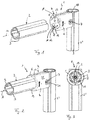
- Fig. 1
- ein erfindungsgemäßes Profilrohrsystem mit einem an einem weiteren Profilrohr angebundenen erfindungsgemäßen Verbinder und noch nicht eingestecktem Profilrohr,
- Fig. 2
- eine Darstellung wie in
Figur 1 , jedoch in montiertem Zustand, - Fig. 3
- eine Ansicht aus Richtung A auf das erfindungsgemäße Profilrohrsystem,
- Fig. 4
- eine Darstellung wie in
Figur 1 , jedoch bei einem Profilrohrsystem mit einem Doppelrohrprofil, - Fig. 5
- eine Darstellung wie in
Figur 2 , jedoch ebenfalls mit einem Doppelrohrprofil, - Fig. 6
- eine Darstellung wie in
Figur 3 , jedoch ebenfalls mit einem Doppelrohrprofil, - Fig. 7
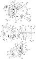
- eine Explosionsdarstellung eines erfindungsgemäßen Verbinders,
- Fig. 8
- einen aus zwei Halbschalen zusammengeschraubten Verbinder,
- Fig. 9
- eine Draufsicht auf den erfindungsgemäßen Verbinder,
- Fig. 10
- eine Innenansicht einer Halbschale des erfindungsgemäßen Verbinders.
- Entsprechend den
Figuren 1 bis 6 , weist ein erfindungsgemäßes Profilrohrsystem 1 zumindest ein Profilrohr 2 mit zumindest zwei parallelen Längsnuten 3 auf. Darüber hinaus besitzt das erfindungsgemäße Profilrohrsystem 1 einen Verbinder 4 (vergleiche auch dieFiguren 7 bis 10 ) zum längsendseitigen Anbringen an dem Profilrohr 2, wobei der Verbinder 4 eine erste Halbschale 5 und eine zweite Halbschale 6 aufweist, die über eine Schraubverbindung 7 miteinander verschraubbar sind. Der Verbinder 4 besitzt eine sacklochartige Rohraufnahme 8 mit einem Boden 9, in welche das Profilrohr 2, vorzugsweise bis zum Boden 9, einsteckbar ist und in der das Profilrohr 2 über die zwei fest miteinander verschraubten Halbschalen 5, 6 fixierbar ist. Um eine Verdrehsicherung für das Profilrohr 2 um seine Längsachse 10 konstruktiv einfach, kostengünstig und zugleich montagefreundlich erreichen zu können, ist an einer Innenmantelfläche der Rohraufnahme 8 der ersten und/oder zweiten Halbschale 5, 6 zumindest eine nach radial innen abstehende Nase 11 angeordnet, die in montiertem Zustand (vergleiche insbesondere dieFiguren 3 und4 ) in eine Längsnut 3 des Profilrohrs 2 eingreift und dadurch eine Verdrehsicherung für dieses bildet. - Betrachtet man die Nase 11 näher, so kann man erkennen, dass diese vorzugsweise eine trapezförmige Gestalt aufweist und sich in Umfangsrichtung der Innenmantelfläche der Rohraufnahme 8 der Halbschale 5, 6 erstreckt (vergleiche die
Figuren 8 und 10 ) und in Axialrichtung (entlang der Längsachse 10) eine deutlich geringere Dicke aufweist als in Umfangsrichtung. Durch die trapezförmige Ausgestaltung der Nase 11 wird ein Einführen derselben in eine zugehörige Längsnut 3 des Profilrohrs 2 vereinfacht. Durch die unterschiedliche Dicke der Nase 11 in Umfangsrichtung bzw. in Axialrichtung, lässt sich die Nase 11 durch ein Werkzeug, beispielsweise einen Schraubenziehers, zudem vergleichsweise einfach abknicken und abbrechen, wodurch es vergleichsweise einfach möglich ist, ein entsprechendes Profilrohr 2 drehwinkelunabhängig in der Rohraufnahme 8 zu montieren. Dabei kann die zumindest eine Nase 11 eine Sollbruchstelle aufweisen, welche das Abknicken und schließlich auch das Abbrechen der Nase 11 vereinfacht. - Betrachtet man die
Figuren 1 ,4 ,7, 8 und 10 weiter, so kann man erkennen, dass die Nase 11 zudem in einer an der Innenmantelfläche der Rohraufnahme 8 angeordneten Vertiefung 12 angeordnet ist, sodass bei einem Abbrechen der Nase 11 und damit einem Entfernen der Verdrehsicherung kein Material über die Innenoberfläche der Rohraufnahme 8 übersteht und dadurch unter Umständen ein Verdrehen des in der Rohraufnahme 8 aufgenommenen Profilrohrs 2 behindert. Dabei ist selbstverständlich klar, dass die Nase 11 trotz ihrer Anordnung in der Vertiefung 12 in nicht abgebrochenem Zustand nach innen über die Innenoberfläche der Rohraufnahme 8 übersteht. Die Sollbruchstelle der Nase 11 liegt dabei in der Vertiefung 12, so dass nach dem Abbrechen der Nase 11 eine halbschalenseitige Bruchfläche in der Vertiefung 12 liegt, das heißt radial außerhalb der Innenmantelfläche der Rohraufnahme 8 und dadurch keinen Kontakt zu einem später in der Rohraufnahme 8 montierten Profilrohr 2 besitzt. Die Vertiefung 12 bietet weiter den Vorteil eines Widerlagers zum Heraushebeln/Abbrechen der Nase 11. Die Vertiefung 12 bildet beispielsweise eine Anlage-/Abstützfläche über die mit bspw. einem Schraubendreher gehebelt werden kann. - Mit der erfindungsgemäßen Nase 11 kann somit eine vergleichsweise einfache, kostengünstige und zugleich montagefreundliche Verdrehsicherung erreicht werden, da die Nase 11 vorzugsweise einstückig mit der jeweiligen Halbschale 5, 6 ausgebildet ist, sodass zur Herstellung der Nase 11 lediglich ein Herstellungswerkzeug, beispielweise ein Druckgusswerkzeug, sofern die Halbschale 5, 6 aus Aluminium gefertigt ist, angepasst werden muss. Bislang erfolgte eine derartige Verdrehsicherung über zusätzliche Bauteile, wie beispielsweise ein Fliesenkreuz, welches in einer zugehörigen Ausnehmung 13 am Boden 9 der Rohraufnahme 8 montiert und/oder in das Profilrohr 2 eingesetzt werden musste. Selbstverständlich kann ein derartiges Fliesenkreuz auch bei dem erfindungsgemäßen Verbinder 4 zusätzlich vorgesehen werden. Für eine Verdrehsicherung ist es jedoch nicht mehr erforderlich.
- Betrachtet man den erfindungsgemäßen Verbinder 4 näher, so kann man erkennen, dass jede Halbschale 5, 6 an einem ersten Halbschalenlängsrand 14 eine Nut 15 und an einem zweiten Halbschalenlängsrand 16 eine komplementär zur Nut 11 ausgebildete Feder 17 aufweist, sodass die beiden Halbschalen 5, 6 in montiertem Zustand an ihren Halbschalenlängsrändern 14, 16 jeweils über eine zumindest teilweise geschlossene Nut- und Federverbindung miteinander verbunden und über diese auch zu einander ausgerichtet/positioniert sind. In einem Bereich 18 der sacklochartigen Rohraufnahme 8 ist dabei am ersten Halbschalenlängsrand 14 keine Nut 15 und am zweiten Halbschalenlängsrand 16 keine zugehörige Feder 17 vorgesehen, sodass die beiden Halbschalenlängsränder 14, 16 in diesem Bereich 18 voneinander beabstandet sind und einen Schlitz 19 (vergleiche insbesondere die
Figur 9 ) bilden. Dies bietet den besonderen Vorteil, dass mit dem erfindungsgemäßen Verbinder 4 auch sogenannte Doppelrohrprofile 20 (vergleiche dieFiguren 4 bis 6 ) mit zwei parallelen Profilrohren 2 und einem diese verbindenden Steg 21 vergleichsweise einfach an ein weiteres Profilrohr 2' angeschlossen werden können. Dies war mit bislang aus dem Stand der Technik bekannten Verbindern nicht möglich, da diese den erfindungsgemäßen Schlitz 19 nicht aufwiesen, sodass bei diesen der Steg 21 im Bereich der beiden Verbinder 4 entfernt werden musste, was aufwendig war. Mit den erfindungsgemäßen Verbindern 4 ist es möglich, diese auf zwei benachbarte Längsenden der Profilrohre 2 des Doppelrohrprofils 20 derart aufzustecken, dass der Steg 21 des Doppelrohrprofils 20 durch den Schlitz 19 zwischen den Halbschalen 5, 6 geführt ist. - Betrachtet man die beiden Halbschalen 5, 6, so kann man erkennen, dass diese als Gleichteile ausgebildet sind, wodurch diese kostengünstig herstellbar sind. Darüber hinaus besitzt jede Halbschale 5, 6 ein insbesondere quaderförmiges Positionierelement 22 sowie eine ebenfalls quaderförmige Positionieröffnung 23, welche bei miteinander verbundenen Halbschalen 5, 6 mit den Positionieröffnungen 23 bzw. Positionierelementen 22 der gegenüberliegenden Halbschale 6, 5 zusammen wirken und dadurch eine eindeutige Lagefixierung zwischen beiden Halbschalen 5, 6 erzwingen.
- Jede Halbschale 5, 6 weist darüber hinaus eine quer zur Längsrichtung (Achsrichtung der Rohraufnahme 8) verlaufende Durchgangsöffnung 24 für die Schraubverbindung 7 auf, wobei in jeder Halbschale 5, 6 eine von einem Halbschalenrücken 25 zugängliche Aufnahme 26 für eine Mutter 27 der Schraubverbindung 7 vorgesehen, in der die Mutter 27 formschlüssig aufnehmbar ist (vergleiche insbesondere die
Figur 7 ). - Darüber hinaus besitzt jede Halbschale 5, 6 an ihrem der Rohraufnahme 8 abgewandten Längsende eine quer zur Längsrichtung 10 ausgerichtete Kante 28 mit einer Hinterschnittkontur 29, sodass der Verbinder 4 im montierten Zustand mit seinen beiden Kanten 20 in zugehörige Längsnuten/Profilnuten 3 eines weiteren Profilrohrs 2' eingreifen kann und darüber an dem weiteren Profilrohr 2' fixierbar ist. Die Hinterschnittkonturen 29 besitzen dabei vorzugsweise einen abgerundeten Boden 30, der komplementär zu einer runden Außenkontur des weiteren Profilrohrs 2' ausgebildet ist und dadurch vorzugsweise flächig an dieser anliegt.
- Mit dem erfindungsgemäßen Verbinder 4 und dem erfindungsgemäßen Profilrohrsystem 1 lässt sich somit eine Verdrehsicherung eines Profilrohrs 2 in dem Verbinder 4 mittels der erfindungsgemäßen Nase 11 vergleichsweise einfach realisieren, wobei durch die vorzugsweise leichte Abbrechbarkeit der Nasen 11 auch eine drehwinkelunabhängige Fixierung der Profilrohre 2 im Verbinder 4 möglich ist. Über die erfindungsgemäß vorgesehenen Schlitze 19 kann mit den erfindungsgemäßen Verbindern 4 auch ein Doppelrohrprofil 20 ohne weitere Bearbeitung vergleichsweise einfach montiert werden.
Claims (11)
- Profilrohrsystem (1)- mit zumindest einem Profilrohr (2) mit zumindest zwei parallelen Längsnuten (3),- mit einem Verbinder (4) zum längsendseitigen Anbringen an dem Profilrohr (2), der eine erste Halbschale (5) und eine zweite Halbschale (6) aufweist, die über eine Schraubverbindung (7) miteinander verschraubbar sind,- wobei der Verbinder (4) eine sacklochartige Rohraufnahme (8) mit einem Boden (9) aufweist, in welche das Profilrohr (2) einsteckbar und in der das Profilrohr (2) über die zwei fest miteinander verschraubten Halbschalen (5,6) fixierbar ist,- wobei an einer Innenmantelfläche der Rohraufnahme (8) der ersten und/oder zweiten Halbschale (5,6) zumindest eine nach innen abstehende Nase (11) angeordnet ist, die in montiertem Zustand in eine Längsnut (3) des Profilrohrs (2) eingreift und eine Verdrehsicherung für dieses bildet, dadurch gekennzeichnet,- dass die zumindest eine Nase (11) eine Sollbruchstelle aufweist und durch ein Knicken abbrechbar ist, wodurch eine drehwinkelunabhängige Fixierung des Profilrohrs (2) in der Rohraufnahme (8) realisierbar ist,- dass die Nase (11) in einer an der Innenmantelfläche der Rohraufnahme (8) angeordneten Vertiefung (12) angeordnet ist.
- Profilrohrsystem nach Anspruch 1,
dadurch gekennzeichnet,- dass jede Halbschale (5,6) an einem ersten Halbschalenlängsrand (14) eine Nut (15) und an einem zweiten Halbschalenlängsrand (16) eine komplementär dazu ausgebildete Feder (17) aufweist, so dass die beiden Halbschalen (5,6) in montiertem Zustand an ihren Halbschalenlängsrändern (14,16) jeweils über eine teilweise geschlossene Nut- und Federverbindung miteinander verbunden sind,- dass im Bereich der Rohraufnahme (8) am ersten Halbschalenlängsrand (14) keine Nut (15) und am zweiten Halbschalenlängsrand (16) keine Feder (17) vorgesehen ist, sodass die beiden Halbschalenlängsränder (14,16) in diesem Bereich (18) voneinander beabstandet sind und einen Schlitz (19) bilden. - Profilrohrsystem nach Anspruch 1 oder 2,
dadurch gekennzeichnet,
dass ein Doppelrohrprofil (20) mit zwei parallelen Profilrohren (2) vorgesehen ist, die über einen Steg (21) miteinander verbunden sind, wobei auf zwei benachbarte Längsenden der Profilrohre (2) des Doppelrohrprofils (20) jeweils ein Verbinder (4) derart aufgesteckt ist, dass der Steg (21) des Doppelrohrprofils (20) durch den Schlitz (19) zwischen den Halbschalen (5,6) geführt ist. - Profilrohrsystem nach einem der vorhergehenden Ansprüche,
dadurch gekennzeichnet,- dass jede Halbschale (5,6) eine quer zur Längsrichtung verlaufende Durchgangsöffnung (24) für die Schraubverbindung (7) aufweist, wobei in jeder Halbschale (5,6) eine von einem Halbschalenrücken (25) zugängige Aufnahme (26) für eine Mutter (27) der Schraubverbindung (7) vorgesehen ist, in der die Mutter (27) formschlüssig aufnehmbar ist, und/oder- dass die erste und die zweite Halbschale (5,6) als Gleichteile ausgebildet sind. - Profilrohrsystem nach einem der vorhergehenden Ansprüche,
dadurch gekennzeichnet,
dass jede Halbschale (5,6) an ihrem der Rohraufnahme (8) abgewandten Längsende eine quer zur Längsrichtung ausgerichtete Kante (28) mit einer Hinterschnittkontur (29) aufweist, so dass der Verbinder (4) in montiertem Zustand mit seinen beiden Kanten (28) in zugehörige Längsnuten (3) eines weiteren Profilrohres (2') eingreifen kann und darüber an dem weiteren Profilrohr (2') fixierbar ist. - Profilrohrsystem nach Anspruch 5,
dadurch gekennzeichnet,
dass die Hinterschnittkonturen (29) in einen abgerundeten Boden (30) übergehen, der komplementär zu einer runden Außenkontur des weiteren Profilrohrs (2') ausgebildet ist. - Verbinder (4) für ein Profilrohrsystem (1) nach Anspruch 1- mit einer ersten Halbschale (5) und einer zweiten Halbschale (6), die über eine Schraubverbindung (7) miteinander verschraubbar sind,- mit einer sacklochartigen Rohraufnahme (8) mit einem Boden (9), dadurch gekennzeichnet,- dass an einer Innenmantelfläche der Rohraufnahme (8) der ersten und/oder zweiten Halbschale (5,6) zumindest eine nach innen abstehende Nase (11) angeordnet ist, die eine Sollbruchstelle aufweist und durch ein Knicken abbrechbar ist,- dass die Nase (11) in einer an der Innenmantelfläche der Rohraufnahme (8) angeordneten Vertiefung (12) angeordnet ist.
- Verbinder nach Anspruch 7,
dadurch gekennzeichnet,- dass jede Halbschale (5,6) an einem ersten Halbschalenlängsrand (14) eine Nut (15) und an einem zweiten Halbschalenlängsrand (16) eine komplementär dazu ausgebildete Feder (17) aufweist, so dass die beiden Halbschalen (5,6) in montiertem Zustand an ihren Halbschalenlängsrändern (14,16) jeweils über eine teilweise geschlossene Nut- und Federverbindung miteinander verbunden sind,- dass im Bereich (18) der Rohraufnahme (8) am ersten Halbschalenlängsrand (14) keine Nut (15) und am zweiten Halbschalenlängsrand (16) keine Feder (17) vorgesehen ist, sodass die beiden Halbschalenlängsränder (14,16) in diesem Bereich (18) voneinander beabstandet sind und einen Schlitz (19) bilden. - Verbinder nach einem der Ansprüche 7 oder 8,
dadurch gekennzeichnet,
dass die erste und die zweite Halbschale (5,6) als Gleichteile ausgebildet sind. - Verbinder nach einem der Ansprüche 7 bis 9,
dadurch gekennzeichnet,
dass jede Halbschale (5,6) an ihrem der Rohraufnahme (8) abgewandten Längsende eine quer zur Längsrichtung ausgerichtete Kante (28) mit einer Hinterschnittkontur (29) aufweist. - Verbinder nach Anspruch 10,
dadurch gekennzeichnet,
dass die Hinterschnittkonturen (29) in einen abgerundeten Boden (30) übergehen.
Applications Claiming Priority (1)
| Application Number | Priority Date | Filing Date | Title |
|---|---|---|---|
| DE102018216086.4A DE102018216086A1 (de) | 2018-09-20 | 2018-09-20 | Profilrohrsystem |
Publications (2)
| Publication Number | Publication Date |
|---|---|
| EP3626898A1 EP3626898A1 (de) | 2020-03-25 |
| EP3626898B1 true EP3626898B1 (de) | 2020-12-09 |
Family
ID=67902314
Family Applications (1)
| Application Number | Title | Priority Date | Filing Date |
|---|---|---|---|
| EP19195374.4A Active EP3626898B1 (de) | 2018-09-20 | 2019-09-04 | Profilrohrsystem |
Country Status (2)
| Country | Link |
|---|---|
| EP (1) | EP3626898B1 (de) |
| DE (1) | DE102018216086A1 (de) |
Families Citing this family (1)
| Publication number | Priority date | Publication date | Assignee | Title |
|---|---|---|---|---|
| CN115071508B (zh) * | 2022-07-11 | 2023-03-28 | 宝鸡保德利电气设备有限责任公司 | 一种组装式腕臂支撑定位装置 |
Citations (5)
| Publication number | Priority date | Publication date | Assignee | Title |
|---|---|---|---|---|
| JP2003172323A (ja) | 2001-12-03 | 2003-06-20 | Sus Corp | プロファイルコネクタおよびプロファイルの接合構造 |
| DE202005007822U1 (de) | 2005-04-01 | 2005-10-13 | Ipeg Gmbh - Ingenieurdienstleistungen | Adaptive Basistruktur zur Aufnahme von handelsüblichen Möbelverbindern |
| EP1617087A1 (de) | 2004-07-13 | 2006-01-18 | NORGREN Automotive GmbH | Trageinrichtung |
| DE202009008687U1 (de) | 2009-06-18 | 2010-11-04 | Rixen, Wolfgang, Dipl.-Ing. | Profilstabverbindungssystem |
| DE102009042238A1 (de) | 2009-09-18 | 2011-04-07 | Robert Bosch Gmbh | Klemmbauteil mit einer Schneide zur Herstellung einer elektrisch leitenden Verbindung |
Family Cites Families (1)
| Publication number | Priority date | Publication date | Assignee | Title |
|---|---|---|---|---|
| DE10017897C2 (de) * | 2000-04-11 | 2002-09-26 | Tuenkers Maschinenbau Gmbh | Gerüstsystem, zur Verwendung im Karosseriebau der Kfz-Industrie, zum Anordnen von Kniehebelspannvorrichtungen, Saugvorrichtungen, Zentrierdornen, Sensoren, Schweißvorrichtungen, Clinchvorrichtungen, Nietvorrichtungen o. dgl., z. B. zur Verbindung mit einem Roboterarm oder dergleichen |
-
2018
- 2018-09-20 DE DE102018216086.4A patent/DE102018216086A1/de not_active Withdrawn
-
2019
- 2019-09-04 EP EP19195374.4A patent/EP3626898B1/de active Active
Patent Citations (5)
| Publication number | Priority date | Publication date | Assignee | Title |
|---|---|---|---|---|
| JP2003172323A (ja) | 2001-12-03 | 2003-06-20 | Sus Corp | プロファイルコネクタおよびプロファイルの接合構造 |
| EP1617087A1 (de) | 2004-07-13 | 2006-01-18 | NORGREN Automotive GmbH | Trageinrichtung |
| DE202005007822U1 (de) | 2005-04-01 | 2005-10-13 | Ipeg Gmbh - Ingenieurdienstleistungen | Adaptive Basistruktur zur Aufnahme von handelsüblichen Möbelverbindern |
| DE202009008687U1 (de) | 2009-06-18 | 2010-11-04 | Rixen, Wolfgang, Dipl.-Ing. | Profilstabverbindungssystem |
| DE102009042238A1 (de) | 2009-09-18 | 2011-04-07 | Robert Bosch Gmbh | Klemmbauteil mit einer Schneide zur Herstellung einer elektrisch leitenden Verbindung |
Non-Patent Citations (9)
| Title |
|---|
| ANONYMOUS ET AL: "Mechanik-Grundelemente", KATALOG MGE 13.0, 6 September 2012 (2012-09-06), XP055427109, Retrieved from the Internet <URL:http://www.betz.cz/download_soubory/Katalog_MGE_13.0_DE.pdf> [retrieved on 20171121] * |
| ANONYMOUS: "Aluminium-Selbstbauelemente", BOSCH FLEXIBLE AUTOMATION, March 1996 (1996-03-01), pages 1 - 3, XP055699981 |
| ANONYMOUS: "ALU-Profil-Systeme", MSI (MONTAGE-SYSTEME-INDUSTRIEAUSRÜSTUNG), 2009, pages 1 - 2, XP055699985 |
| ANONYMOUS: "Die Baureihe D30-das Lean Production System 2.1", ITEM INDUSTRIETECHNIK, January 2014 (2014-01-01), pages 37, XP055700005 |
| ANONYMOUS: "Innovationen mit System. Neuheiten Herbst 2011", ITEM INDUSTRIETECHNIK, 1 September 2011 (2011-09-01), pages 1 - 3, XP055699999 |
| ANONYMOUS: "Katalog Kompatible Profilreihen und System-Engineering1", FM SYSTEME, vol. 4, no. 02, 1 August 2014 (2014-08-01), pages - 3, XP055699988 |
| ANONYMOUS: "MB Systembaukasten (MB8) Der Gesamtkatalog", ITEM INDUSTRIETECHNIK, 1 March 2012 (2012-03-01), pages 114, XP055700007 |
| ANONYMOUS: "MB Systembaukasten (MB9) Der Gesamtkatalog", ITEM VERBINDUNGSTECHNIK, 1 October 2016 (2016-10-01), pages 95 - 101, XP055699996 |
| ANONYMOUS: "Mechanik-Grundelemente 13.2", REXROTH BOSCH GROUP, August 2017 (2017-08-01), pages 1 - 6, XP055699976 |
Also Published As
| Publication number | Publication date |
|---|---|
| EP3626898A1 (de) | 2020-03-25 |
| DE102018216086A1 (de) | 2020-03-26 |
Similar Documents
| Publication | Publication Date | Title |
|---|---|---|
| EP3717786B1 (de) | Toleranzausgleichsanordnung mit klemmsicherung | |
| EP2318723B1 (de) | Befestigungsanordnung mit toleranzausgleich | |
| EP2757299B1 (de) | Rohrklemme | |
| EP2481939B1 (de) | Spannschelle | |
| EP2459425B1 (de) | Baugruppe bestehend aus einem ausgleichsbehälter und einem hauptzylinder für eine hydraulische kraftfahrzeugbremsanlage | |
| EP3004702B1 (de) | Kombination aus einem gehäuse und einem ventil | |
| EP4239233B1 (de) | Halbverschraubung und verfahren zur montage einer halbverschraubung | |
| EP3353460B1 (de) | Verschlussschraube | |
| DE10315690B4 (de) | Befestigungsvorrichtung für eine Anhängevorrichtung an einem Längsträger eines Kraftfahrzeuges | |
| EP2019765B1 (de) | Vorrichtung und verfahren zur befestigung eines wischermotors an ein wischergestänge | |
| EP1828623B1 (de) | Vorrichtung zum befestigen eines anbauteils und eines trägerteiles in einem abstand voneinander | |
| DE102021100676A1 (de) | Halteelement zum Befestigen eines Anbauteils | |
| EP2775187B1 (de) | Vorrichtung für eine schlaucharmatur | |
| EP3581811B1 (de) | System zur befestigung einer ersten komponente an einer zweiten komponente | |
| EP3105483B1 (de) | Schelle | |
| DE102023207479A1 (de) | Vorrichtung zum Ausgleichen von Toleranzen | |
| DE10200376A1 (de) | Befestigungsvorrichtung | |
| EP2038497A1 (de) | Vorrichtung zur befestigung von beschlagteilen an hohlkammerprofilen | |
| EP2568207B1 (de) | Rohrverbinder | |
| WO2018077665A1 (de) | Befestigungsanordnung | |
| EP3626898A1 (de) | Profilrohrsystem | |
| EP1713991B1 (de) | Türdrückerpaar mit Türdrückerklemmbefestigung | |
| EP2102038B1 (de) | Gehäuseanordnung einer wischeranlage mit schraubverbindung | |
| EP3366851B1 (de) | Universal-füllventil-set | |
| EP4090854B1 (de) | Widerlagerhülse |
Legal Events
| Date | Code | Title | Description |
|---|---|---|---|
| PUAI | Public reference made under article 153(3) epc to a published international application that has entered the european phase |
Free format text: ORIGINAL CODE: 0009012 |
|
| STAA | Information on the status of an ep patent application or granted ep patent |
Free format text: STATUS: THE APPLICATION HAS BEEN PUBLISHED |
|
| AK | Designated contracting states |
Kind code of ref document: A1 Designated state(s): AL AT BE BG CH CY CZ DE DK EE ES FI FR GB GR HR HU IE IS IT LI LT LU LV MC MK MT NL NO PL PT RO RS SE SI SK SM TR |
|
| AX | Request for extension of the european patent |
Extension state: BA ME |
|
| STAA | Information on the status of an ep patent application or granted ep patent |
Free format text: STATUS: REQUEST FOR EXAMINATION WAS MADE |
|
| TPAC | Observations filed by third parties |
Free format text: ORIGINAL CODE: EPIDOSNTIPA |
|
| 17P | Request for examination filed |
Effective date: 20200423 |
|
| RBV | Designated contracting states (corrected) |
Designated state(s): AL AT BE BG CH CY CZ DE DK EE ES FI FR GB GR HR HU IE IS IT LI LT LU LV MC MK MT NL NO PL PT RO RS SE SI SK SM TR |
|
| RIC1 | Information provided on ipc code assigned before grant |
Ipc: E04B 1/58 20060101AFI20200507BHEP Ipc: E04B 1/24 20060101ALN20200507BHEP Ipc: F16B 7/04 20060101ALI20200507BHEP |
|
| RIC1 | Information provided on ipc code assigned before grant |
Ipc: E04B 1/24 20060101ALN20200512BHEP Ipc: E04B 1/58 20060101AFI20200512BHEP Ipc: F16B 7/04 20060101ALI20200512BHEP |
|
| GRAP | Despatch of communication of intention to grant a patent |
Free format text: ORIGINAL CODE: EPIDOSNIGR1 |
|
| STAA | Information on the status of an ep patent application or granted ep patent |
Free format text: STATUS: GRANT OF PATENT IS INTENDED |
|
| INTG | Intention to grant announced |
Effective date: 20200630 |
|
| GRAS | Grant fee paid |
Free format text: ORIGINAL CODE: EPIDOSNIGR3 |
|
| GRAA | (expected) grant |
Free format text: ORIGINAL CODE: 0009210 |
|
| STAA | Information on the status of an ep patent application or granted ep patent |
Free format text: STATUS: THE PATENT HAS BEEN GRANTED |
|
| AK | Designated contracting states |
Kind code of ref document: B1 Designated state(s): AL AT BE BG CH CY CZ DE DK EE ES FI FR GB GR HR HU IE IS IT LI LT LU LV MC MK MT NL NO PL PT RO RS SE SI SK SM TR |
|
| REG | Reference to a national code |
Ref country code: GB Ref legal event code: FG4D Free format text: NOT ENGLISH |
|
| REG | Reference to a national code |
Ref country code: CH Ref legal event code: EP Ref country code: AT Ref legal event code: REF Ref document number: 1343592 Country of ref document: AT Kind code of ref document: T Effective date: 20201215 |
|
| REG | Reference to a national code |
Ref country code: DE Ref legal event code: R096 Ref document number: 502019000507 Country of ref document: DE |
|
| REG | Reference to a national code |
Ref country code: IE Ref legal event code: FG4D Free format text: LANGUAGE OF EP DOCUMENT: GERMAN |
|
| PG25 | Lapsed in a contracting state [announced via postgrant information from national office to epo] |
Ref country code: RS Free format text: LAPSE BECAUSE OF FAILURE TO SUBMIT A TRANSLATION OF THE DESCRIPTION OR TO PAY THE FEE WITHIN THE PRESCRIBED TIME-LIMIT Effective date: 20201209 Ref country code: FI Free format text: LAPSE BECAUSE OF FAILURE TO SUBMIT A TRANSLATION OF THE DESCRIPTION OR TO PAY THE FEE WITHIN THE PRESCRIBED TIME-LIMIT Effective date: 20201209 Ref country code: NO Free format text: LAPSE BECAUSE OF FAILURE TO SUBMIT A TRANSLATION OF THE DESCRIPTION OR TO PAY THE FEE WITHIN THE PRESCRIBED TIME-LIMIT Effective date: 20210309 Ref country code: GR Free format text: LAPSE BECAUSE OF FAILURE TO SUBMIT A TRANSLATION OF THE DESCRIPTION OR TO PAY THE FEE WITHIN THE PRESCRIBED TIME-LIMIT Effective date: 20210310 |
|
| PG25 | Lapsed in a contracting state [announced via postgrant information from national office to epo] |
Ref country code: BG Free format text: LAPSE BECAUSE OF FAILURE TO SUBMIT A TRANSLATION OF THE DESCRIPTION OR TO PAY THE FEE WITHIN THE PRESCRIBED TIME-LIMIT Effective date: 20210309 Ref country code: SE Free format text: LAPSE BECAUSE OF FAILURE TO SUBMIT A TRANSLATION OF THE DESCRIPTION OR TO PAY THE FEE WITHIN THE PRESCRIBED TIME-LIMIT Effective date: 20201209 Ref country code: LV Free format text: LAPSE BECAUSE OF FAILURE TO SUBMIT A TRANSLATION OF THE DESCRIPTION OR TO PAY THE FEE WITHIN THE PRESCRIBED TIME-LIMIT Effective date: 20201209 |
|
| REG | Reference to a national code |
Ref country code: NL Ref legal event code: MP Effective date: 20201209 |
|
| PG25 | Lapsed in a contracting state [announced via postgrant information from national office to epo] |
Ref country code: HR Free format text: LAPSE BECAUSE OF FAILURE TO SUBMIT A TRANSLATION OF THE DESCRIPTION OR TO PAY THE FEE WITHIN THE PRESCRIBED TIME-LIMIT Effective date: 20201209 Ref country code: NL Free format text: LAPSE BECAUSE OF FAILURE TO SUBMIT A TRANSLATION OF THE DESCRIPTION OR TO PAY THE FEE WITHIN THE PRESCRIBED TIME-LIMIT Effective date: 20201209 |
|
| REG | Reference to a national code |
Ref country code: LT Ref legal event code: MG9D |
|
| PG25 | Lapsed in a contracting state [announced via postgrant information from national office to epo] |
Ref country code: EE Free format text: LAPSE BECAUSE OF FAILURE TO SUBMIT A TRANSLATION OF THE DESCRIPTION OR TO PAY THE FEE WITHIN THE PRESCRIBED TIME-LIMIT Effective date: 20201209 Ref country code: SM Free format text: LAPSE BECAUSE OF FAILURE TO SUBMIT A TRANSLATION OF THE DESCRIPTION OR TO PAY THE FEE WITHIN THE PRESCRIBED TIME-LIMIT Effective date: 20201209 Ref country code: SK Free format text: LAPSE BECAUSE OF FAILURE TO SUBMIT A TRANSLATION OF THE DESCRIPTION OR TO PAY THE FEE WITHIN THE PRESCRIBED TIME-LIMIT Effective date: 20201209 Ref country code: CZ Free format text: LAPSE BECAUSE OF FAILURE TO SUBMIT A TRANSLATION OF THE DESCRIPTION OR TO PAY THE FEE WITHIN THE PRESCRIBED TIME-LIMIT Effective date: 20201209 Ref country code: RO Free format text: LAPSE BECAUSE OF FAILURE TO SUBMIT A TRANSLATION OF THE DESCRIPTION OR TO PAY THE FEE WITHIN THE PRESCRIBED TIME-LIMIT Effective date: 20201209 Ref country code: PT Free format text: LAPSE BECAUSE OF FAILURE TO SUBMIT A TRANSLATION OF THE DESCRIPTION OR TO PAY THE FEE WITHIN THE PRESCRIBED TIME-LIMIT Effective date: 20210409 Ref country code: LT Free format text: LAPSE BECAUSE OF FAILURE TO SUBMIT A TRANSLATION OF THE DESCRIPTION OR TO PAY THE FEE WITHIN THE PRESCRIBED TIME-LIMIT Effective date: 20201209 |
|
| PG25 | Lapsed in a contracting state [announced via postgrant information from national office to epo] |
Ref country code: PL Free format text: LAPSE BECAUSE OF FAILURE TO SUBMIT A TRANSLATION OF THE DESCRIPTION OR TO PAY THE FEE WITHIN THE PRESCRIBED TIME-LIMIT Effective date: 20201209 |
|
| REG | Reference to a national code |
Ref country code: DE Ref legal event code: R026 Ref document number: 502019000507 Country of ref document: DE |
|
| PLBI | Opposition filed |
Free format text: ORIGINAL CODE: 0009260 |
|
| PLAX | Notice of opposition and request to file observation + time limit sent |
Free format text: ORIGINAL CODE: EPIDOSNOBS2 |
|
| PG25 | Lapsed in a contracting state [announced via postgrant information from national office to epo] |
Ref country code: IS Free format text: LAPSE BECAUSE OF FAILURE TO SUBMIT A TRANSLATION OF THE DESCRIPTION OR TO PAY THE FEE WITHIN THE PRESCRIBED TIME-LIMIT Effective date: 20210409 |
|
| 26 | Opposition filed |
Opponent name: FATH GMBH Effective date: 20210907 |
|
| PG25 | Lapsed in a contracting state [announced via postgrant information from national office to epo] |
Ref country code: AL Free format text: LAPSE BECAUSE OF FAILURE TO SUBMIT A TRANSLATION OF THE DESCRIPTION OR TO PAY THE FEE WITHIN THE PRESCRIBED TIME-LIMIT Effective date: 20201209 Ref country code: IT Free format text: LAPSE BECAUSE OF FAILURE TO SUBMIT A TRANSLATION OF THE DESCRIPTION OR TO PAY THE FEE WITHIN THE PRESCRIBED TIME-LIMIT Effective date: 20201209 |
|
| PG25 | Lapsed in a contracting state [announced via postgrant information from national office to epo] |
Ref country code: DK Free format text: LAPSE BECAUSE OF FAILURE TO SUBMIT A TRANSLATION OF THE DESCRIPTION OR TO PAY THE FEE WITHIN THE PRESCRIBED TIME-LIMIT Effective date: 20201209 Ref country code: SI Free format text: LAPSE BECAUSE OF FAILURE TO SUBMIT A TRANSLATION OF THE DESCRIPTION OR TO PAY THE FEE WITHIN THE PRESCRIBED TIME-LIMIT Effective date: 20201209 |
|
| PG25 | Lapsed in a contracting state [announced via postgrant information from national office to epo] |
Ref country code: ES Free format text: LAPSE BECAUSE OF FAILURE TO SUBMIT A TRANSLATION OF THE DESCRIPTION OR TO PAY THE FEE WITHIN THE PRESCRIBED TIME-LIMIT Effective date: 20201209 |
|
| PLBB | Reply of patent proprietor to notice(s) of opposition received |
Free format text: ORIGINAL CODE: EPIDOSNOBS3 |
|
| REG | Reference to a national code |
Ref country code: BE Ref legal event code: MM Effective date: 20210930 |
|
| PG25 | Lapsed in a contracting state [announced via postgrant information from national office to epo] |
Ref country code: IS Free format text: LAPSE BECAUSE OF FAILURE TO SUBMIT A TRANSLATION OF THE DESCRIPTION OR TO PAY THE FEE WITHIN THE PRESCRIBED TIME-LIMIT Effective date: 20210409 Ref country code: MC Free format text: LAPSE BECAUSE OF FAILURE TO SUBMIT A TRANSLATION OF THE DESCRIPTION OR TO PAY THE FEE WITHIN THE PRESCRIBED TIME-LIMIT Effective date: 20201209 |
|
| PG25 | Lapsed in a contracting state [announced via postgrant information from national office to epo] |
Ref country code: LU Free format text: LAPSE BECAUSE OF NON-PAYMENT OF DUE FEES Effective date: 20210904 Ref country code: IE Free format text: LAPSE BECAUSE OF NON-PAYMENT OF DUE FEES Effective date: 20210904 Ref country code: BE Free format text: LAPSE BECAUSE OF NON-PAYMENT OF DUE FEES Effective date: 20210930 |
|
| PLBD | Termination of opposition procedure: decision despatched |
Free format text: ORIGINAL CODE: EPIDOSNOPC1 |
|
| PLBP | Opposition withdrawn |
Free format text: ORIGINAL CODE: 0009264 |
|
| REG | Reference to a national code |
Ref country code: DE Ref legal event code: R100 Ref document number: 502019000507 Country of ref document: DE |
|
| REG | Reference to a national code |
Ref country code: CH Ref legal event code: PL |
|
| PG25 | Lapsed in a contracting state [announced via postgrant information from national office to epo] |
Ref country code: CY Free format text: LAPSE BECAUSE OF FAILURE TO SUBMIT A TRANSLATION OF THE DESCRIPTION OR TO PAY THE FEE WITHIN THE PRESCRIBED TIME-LIMIT Effective date: 20201209 |
|
| PLBM | Termination of opposition procedure: date of legal effect published |
Free format text: ORIGINAL CODE: 0009276 |
|
| PG25 | Lapsed in a contracting state [announced via postgrant information from national office to epo] |
Ref country code: LI Free format text: LAPSE BECAUSE OF NON-PAYMENT OF DUE FEES Effective date: 20220930 Ref country code: HU Free format text: LAPSE BECAUSE OF FAILURE TO SUBMIT A TRANSLATION OF THE DESCRIPTION OR TO PAY THE FEE WITHIN THE PRESCRIBED TIME-LIMIT; INVALID AB INITIO Effective date: 20190904 Ref country code: CH Free format text: LAPSE BECAUSE OF NON-PAYMENT OF DUE FEES Effective date: 20220930 |
|
| P01 | Opt-out of the competence of the unified patent court (upc) registered |
Effective date: 20230628 |
|
| 27C | Opposition proceedings terminated |
Effective date: 20230421 |
|
| PG25 | Lapsed in a contracting state [announced via postgrant information from national office to epo] |
Ref country code: MK Free format text: LAPSE BECAUSE OF FAILURE TO SUBMIT A TRANSLATION OF THE DESCRIPTION OR TO PAY THE FEE WITHIN THE PRESCRIBED TIME-LIMIT Effective date: 20201209 |
|
| PG25 | Lapsed in a contracting state [announced via postgrant information from national office to epo] |
Ref country code: TR Free format text: LAPSE BECAUSE OF FAILURE TO SUBMIT A TRANSLATION OF THE DESCRIPTION OR TO PAY THE FEE WITHIN THE PRESCRIBED TIME-LIMIT Effective date: 20201209 |
|
| PG25 | Lapsed in a contracting state [announced via postgrant information from national office to epo] |
Ref country code: MT Free format text: LAPSE BECAUSE OF FAILURE TO SUBMIT A TRANSLATION OF THE DESCRIPTION OR TO PAY THE FEE WITHIN THE PRESCRIBED TIME-LIMIT Effective date: 20201209 |
|
| PGFP | Annual fee paid to national office [announced via postgrant information from national office to epo] |
Ref country code: DE Payment date: 20250926 Year of fee payment: 7 |
|
| PGFP | Annual fee paid to national office [announced via postgrant information from national office to epo] |
Ref country code: GB Payment date: 20250923 Year of fee payment: 7 |
|
| PGFP | Annual fee paid to national office [announced via postgrant information from national office to epo] |
Ref country code: FR Payment date: 20250925 Year of fee payment: 7 |
|
| REG | Reference to a national code |
Ref country code: AT Ref legal event code: MM01 Ref document number: 1343592 Country of ref document: AT Kind code of ref document: T Effective date: 20240904 |
|
| PG25 | Lapsed in a contracting state [announced via postgrant information from national office to epo] |
Ref country code: AT Free format text: LAPSE BECAUSE OF NON-PAYMENT OF DUE FEES Effective date: 20240904 |
|
| PGFP | Annual fee paid to national office [announced via postgrant information from national office to epo] |
Ref country code: AT Payment date: 20260410 Year of fee payment: 5 |