EP3626557A1 - Bremsensystem für ein fahrzeug - Google Patents
Bremsensystem für ein fahrzeug Download PDFInfo
- Publication number
- EP3626557A1 EP3626557A1 EP18195165.8A EP18195165A EP3626557A1 EP 3626557 A1 EP3626557 A1 EP 3626557A1 EP 18195165 A EP18195165 A EP 18195165A EP 3626557 A1 EP3626557 A1 EP 3626557A1
- Authority
- EP
- European Patent Office
- Prior art keywords
- brake
- unit
- pressure modulator
- electronic
- parking brake
- Prior art date
- Legal status (The legal status is an assumption and is not a legal conclusion. Google has not performed a legal analysis and makes no representation as to the accuracy of the status listed.)
- Granted
Links
- 230000007257 malfunction Effects 0.000 claims description 25
- 238000000034 method Methods 0.000 claims description 16
- 230000001276 controlling effect Effects 0.000 description 15
- 238000012806 monitoring device Methods 0.000 description 6
- 230000009286 beneficial effect Effects 0.000 description 2
- 238000012544 monitoring process Methods 0.000 description 1
- 230000001105 regulatory effect Effects 0.000 description 1
Images


Classifications
-
- B—PERFORMING OPERATIONS; TRANSPORTING
- B60—VEHICLES IN GENERAL
- B60T—VEHICLE BRAKE CONTROL SYSTEMS OR PARTS THEREOF; BRAKE CONTROL SYSTEMS OR PARTS THEREOF, IN GENERAL; ARRANGEMENT OF BRAKING ELEMENTS ON VEHICLES IN GENERAL; PORTABLE DEVICES FOR PREVENTING UNWANTED MOVEMENT OF VEHICLES; VEHICLE MODIFICATIONS TO FACILITATE COOLING OF BRAKES
- B60T13/00—Transmitting braking action from initiating means to ultimate brake actuator with power assistance or drive; Brake systems incorporating such transmitting means, e.g. air-pressure brake systems
- B60T13/10—Transmitting braking action from initiating means to ultimate brake actuator with power assistance or drive; Brake systems incorporating such transmitting means, e.g. air-pressure brake systems with fluid assistance, drive, or release
- B60T13/58—Combined or convertible systems
-
- B—PERFORMING OPERATIONS; TRANSPORTING
- B60—VEHICLES IN GENERAL
- B60T—VEHICLE BRAKE CONTROL SYSTEMS OR PARTS THEREOF; BRAKE CONTROL SYSTEMS OR PARTS THEREOF, IN GENERAL; ARRANGEMENT OF BRAKING ELEMENTS ON VEHICLES IN GENERAL; PORTABLE DEVICES FOR PREVENTING UNWANTED MOVEMENT OF VEHICLES; VEHICLE MODIFICATIONS TO FACILITATE COOLING OF BRAKES
- B60T13/00—Transmitting braking action from initiating means to ultimate brake actuator with power assistance or drive; Brake systems incorporating such transmitting means, e.g. air-pressure brake systems
- B60T13/10—Transmitting braking action from initiating means to ultimate brake actuator with power assistance or drive; Brake systems incorporating such transmitting means, e.g. air-pressure brake systems with fluid assistance, drive, or release
- B60T13/66—Electrical control in fluid-pressure brake systems
- B60T13/662—Electrical control in fluid-pressure brake systems characterised by specified functions of the control system components
-
- B—PERFORMING OPERATIONS; TRANSPORTING
- B60—VEHICLES IN GENERAL
- B60T—VEHICLE BRAKE CONTROL SYSTEMS OR PARTS THEREOF; BRAKE CONTROL SYSTEMS OR PARTS THEREOF, IN GENERAL; ARRANGEMENT OF BRAKING ELEMENTS ON VEHICLES IN GENERAL; PORTABLE DEVICES FOR PREVENTING UNWANTED MOVEMENT OF VEHICLES; VEHICLE MODIFICATIONS TO FACILITATE COOLING OF BRAKES
- B60T13/00—Transmitting braking action from initiating means to ultimate brake actuator with power assistance or drive; Brake systems incorporating such transmitting means, e.g. air-pressure brake systems
- B60T13/10—Transmitting braking action from initiating means to ultimate brake actuator with power assistance or drive; Brake systems incorporating such transmitting means, e.g. air-pressure brake systems with fluid assistance, drive, or release
- B60T13/66—Electrical control in fluid-pressure brake systems
- B60T13/68—Electrical control in fluid-pressure brake systems by electrically-controlled valves
- B60T13/683—Electrical control in fluid-pressure brake systems by electrically-controlled valves in pneumatic systems or parts thereof
-
- B—PERFORMING OPERATIONS; TRANSPORTING
- B60—VEHICLES IN GENERAL
- B60T—VEHICLE BRAKE CONTROL SYSTEMS OR PARTS THEREOF; BRAKE CONTROL SYSTEMS OR PARTS THEREOF, IN GENERAL; ARRANGEMENT OF BRAKING ELEMENTS ON VEHICLES IN GENERAL; PORTABLE DEVICES FOR PREVENTING UNWANTED MOVEMENT OF VEHICLES; VEHICLE MODIFICATIONS TO FACILITATE COOLING OF BRAKES
- B60T17/00—Component parts, details, or accessories of power brake systems not covered by groups B60T8/00, B60T13/00 or B60T15/00, or presenting other characteristic features
- B60T17/18—Safety devices; Monitoring
-
- B—PERFORMING OPERATIONS; TRANSPORTING
- B60—VEHICLES IN GENERAL
- B60T—VEHICLE BRAKE CONTROL SYSTEMS OR PARTS THEREOF; BRAKE CONTROL SYSTEMS OR PARTS THEREOF, IN GENERAL; ARRANGEMENT OF BRAKING ELEMENTS ON VEHICLES IN GENERAL; PORTABLE DEVICES FOR PREVENTING UNWANTED MOVEMENT OF VEHICLES; VEHICLE MODIFICATIONS TO FACILITATE COOLING OF BRAKES
- B60T2270/00—Further aspects of brake control systems not otherwise provided for
- B60T2270/40—Failsafe aspects of brake control systems
- B60T2270/402—Back-up
-
- B—PERFORMING OPERATIONS; TRANSPORTING
- B60—VEHICLES IN GENERAL
- B60T—VEHICLE BRAKE CONTROL SYSTEMS OR PARTS THEREOF; BRAKE CONTROL SYSTEMS OR PARTS THEREOF, IN GENERAL; ARRANGEMENT OF BRAKING ELEMENTS ON VEHICLES IN GENERAL; PORTABLE DEVICES FOR PREVENTING UNWANTED MOVEMENT OF VEHICLES; VEHICLE MODIFICATIONS TO FACILITATE COOLING OF BRAKES
- B60T2270/00—Further aspects of brake control systems not otherwise provided for
- B60T2270/40—Failsafe aspects of brake control systems
- B60T2270/404—Brake-by-wire or X-by-wire failsafe
-
- B—PERFORMING OPERATIONS; TRANSPORTING
- B60—VEHICLES IN GENERAL
- B60T—VEHICLE BRAKE CONTROL SYSTEMS OR PARTS THEREOF; BRAKE CONTROL SYSTEMS OR PARTS THEREOF, IN GENERAL; ARRANGEMENT OF BRAKING ELEMENTS ON VEHICLES IN GENERAL; PORTABLE DEVICES FOR PREVENTING UNWANTED MOVEMENT OF VEHICLES; VEHICLE MODIFICATIONS TO FACILITATE COOLING OF BRAKES
- B60T2270/00—Further aspects of brake control systems not otherwise provided for
- B60T2270/40—Failsafe aspects of brake control systems
- B60T2270/413—Plausibility monitoring, cross check, redundancy
-
- B—PERFORMING OPERATIONS; TRANSPORTING
- B60—VEHICLES IN GENERAL
- B60T—VEHICLE BRAKE CONTROL SYSTEMS OR PARTS THEREOF; BRAKE CONTROL SYSTEMS OR PARTS THEREOF, IN GENERAL; ARRANGEMENT OF BRAKING ELEMENTS ON VEHICLES IN GENERAL; PORTABLE DEVICES FOR PREVENTING UNWANTED MOVEMENT OF VEHICLES; VEHICLE MODIFICATIONS TO FACILITATE COOLING OF BRAKES
- B60T2270/00—Further aspects of brake control systems not otherwise provided for
- B60T2270/82—Brake-by-Wire, EHB
Definitions
- the present invention relates to a brake system for a vehicle, to a vehicle with said brake system, and to a method of controlling a brake system for a vehicle.
- DE 10 2008 009 043 B3 shows a redundant brake system for a commercial vehicle.
- the system utilizes a parking brake integrated into an air supply unit as a redundant brake actuator.
- a control output of a trailer control module is used as pneumatic control input of axle modulators.
- a redundant brake system or brake system with redundancy by way of the electronic parking brake controller redundantly performing service brake functions may be provided.
- a brake system of a vehicle, particularly a commercial vehicle, with an electro-pneumatic service brake subsystem and an electro-pneumatic parking brake subsystem may be configured so that vehicle axles not equipped with spring brake chambers, e.g. front axles, are electrically controlled by the electronic parking brake controller via a pressure modulator unit.
- additional redundancy can be provided without adding components to a state-of-the-art brake system comprising an electronic parking brake.
- electric redundancy can be ensured, as opposed to pneumatically redundancy provided in conventional brake systems.
- the proposed redundant brake system has a pneumatic layout appropriate for autonomous driving applications.
- failsafe operation of a vehicle brake system can be provided both electrically and pneumatically.
- a brake system for a vehicle comprises:
- the vehicle may be a utility vehicle or commercial vehicle, for example a truck, bus or the like.
- the service brake chambers and the spring brake cylinders may represent brake actuators of the brake system.
- the electric power supply units may be batteries.
- the first electric power supply unit and the electronic brake control unit may form part of an electro-pneumatic service brake subsystem.
- the second electric power supply unit, the electronic parking brake controller and the pressure modulator unit may form part of an electro-pneumatic parking brake subsystem.
- the electro-pneumatic parking brake subsystem may be usable as a redundant service brake subsystem.
- the electro-pneumatic parking brake subsystem may be used to redundantly perform service brake functions in the event of a malfunction of the electro-pneumatic service brake subsystem.
- the electronic parking brake controller may be used instead of the electronic brake control unit to perform service brake functions in the event of a malfunction of the electro-pneumatic service brake subsystem.
- a brake subsystem may also be referred to as a brake circuit.
- the electronic parking brake controller may be configured to issue the control signal as an electric signal.
- the pressure modulator unit may be configured to command the pneumatic control pressure as a proportional pressure.
- the pressure modulator unit may be realized as a stand-alone unit or may be integrated into the first axle pressure modulator or the electronic parking brake controller.
- Such an embodiment offers the advantage that the pressure modulator unit can be realized in a beneficial manner considering system requirements.
- the pressure modulator unit can be realized in a space-saving manner.
- the electronic parking brake controller may be realized as a stand-alone unit or may be integrated into another unit of the brake system. Another unit of the brake system may be a compressed air supply module.
- Another unit of the brake system may be a compressed air supply module.
- the brake system may comprise a trailer control module for controlling braking functions of a trailer of the vehicle.
- the trailer control module may be connected to the electronic brake control unit.
- the electronic parking brake controller may be fluidically connected to the trailer control module.
- the brake system may comprise a further pressure modulator unit.
- the further pressure modulator unit may be fluidically connected to the trailer control module.
- the further pressure modulator unit may be connected to the electronic parking brake controller.
- the electronic parking brake controller may be configured to issue a further control signal for controlling the further pressure modulator unit.
- the further pressure modulator unit may be configured to pneumatically control the trailer control module depending on the further control signal from the electronic parking brake controller.
- the further control signal may be different from or identical with the control signal issued by the electronic parking brake controller to the pressure modulator unit.
- the electronic parking brake controller may be configured to issue the further control signal as an electric signal.
- the further pressure modulator unit may be configured to pneumatically control the trailer control module depending on trailer load.
- a vehicle comprises:
- the first axle pressure modulator may be mounted in the vicinity of the first axle. Further elements of the brake system associated with the first axle pressure modulator, such as the service brake chambers and valves, may also be mounted in the vicinity of the first axle.
- the second axle pressure modulator may be mounted in the vicinity of the second axle. Further elements of the brake system associated with the second axle pressure modulator, such as the spring brake cylinders, may also be mounted in the vicinity of the second axle.
- a method of controlling a brake system for a vehicle wherein the brake system is an embodiment of the aforementioned brake system, comprises:
- the method or the steps of the method may be executed using a controller.
- the method may be executed to control an embodiment of the aforementioned brake system.
- Fig. 1 shows a schematic illustration of a vehicle 100 comprising a brake system 110 according to an embodiment of the present invention.
- the vehicle 100 is a utility vehicle or commercial vehicle, such as a truck.
- the vehicle 100 comprises a first axle 102 and a second axle 104, according to this embodiment.
- the vehicle 100 comprises a controller 106 and the brake system 110.
- the controller 106 is configured to control the brake system 110 by means of a command signal 108.
- the command signal 108 represents service brake commands for performing service brake functions of the brake system 110.
- the controller 106 also be part of the brake system 110.
- the brake system 110 comprises an electro-pneumatic service brake subsystem 112 and an electro-pneumatic parking brake subsystem 114.
- the electro-pneumatic service brake subsystem 112 is configured to perform service brake functions of the brake system.
- the electro-pneumatic parking brake subsystem 114 is configured to perform parking brake functions of the brake system 110. Furthermore, as a backup or to provide redundancy, the electro-pneumatic parking brake subsystem 114 is configured to perform service brake functions instead of the electro-pneumatic service brake subsystem 112.
- the brake system 110 further comprises a monitoring device 116 for monitoring a state of health of the electro-pneumatic service brake subsystem 112 and the electro-pneumatic parking brake subsystem 114.
- the monitoring device 116 may also be part of a system other than the brake system 110.
- the monitoring device 116 is connected to the electro-pneumatic service brake subsystem 112 and to the electro-pneumatic parking brake subsystem 114.
- the monitoring device 116 is configured to detect a potential malfunction of the electro-pneumatic service brake subsystem 112 or of the electro-pneumatic parking brake subsystem 114.
- the monitoring device 116 is configured to output an error signal 118 to the controller 106.
- the error signal 118 represents a malfunction of the electro-pneumatic service brake subsystem 112 or of the electro-pneumatic parking brake subsystem 114.
- the controller 106 In response to the error signal 118, the controller 106 is configured to transmit the command signal 108 to either the electro-pneumatic service brake subsystem 112 or the electro-pneumatic parking brake subsystem 114. More specifically, the controller 106 is configured to transmit the command signal 108 to that subsystem 112 or 114 free from malfunction, as indicated by the error signal 118.
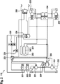
- Fig. 2 shows a schematic illustration of a brake system 110 according to an embodiment of the present invention.
- the brake system 110 is a brake system 110 for a vehicle, specifically a commercial vehicle or utility vehicle, e.g. a truck.
- the brake system 110 corresponds or is similar to the brake system shown in Fig. 1 .
- the brake system 110 comprises a first electric power supply unit 221, a second electric power supply unit 222, an electronic brake control unit 223, electronic parking brake controller 224, a first or front axle pressure modulator 229, a second or rear axle pressure modulator 230, two service brake chambers 232, two spring brake cylinders 233 and a pressure modulator unit 234.
- the brake system 110 further comprises a redundant brake pedal sensor 225, a park brake lever sensor 226, a trailer control module 228, two pressure control valves 231, a first compressed air supply module 241, a second compressed air supply module 242 and a third compressed air supply module 243.
- the first electric power supply unit 221 and the electronic brake control unit 223 form part of the electro-pneumatic service brake subsystem described with reference to Fig. 1 .
- the second electric power supply unit 222, the electronic parking brake controller 224 and the pressure modulator unit 234 form part of the electro-pneumatic parking brake subsystem described with reference to Fig. 1 .
- the electro-pneumatic parking brake subsystem is usable as a redundant service brake subsystem, or in other words to perform service brake functions of the brake system 110.
- the first electric power supply unit 221 is electrically connected to the electronic brake control unit 223.
- the electronic brake control unit 223 is electrically connected to the first axle pressure modulator 229 via an analogous electric signal and supply line and via a digital electric signal line. Furthermore, the electronic brake control unit 223 is electrically connected to the second axle pressure modulator 230 via an analogous electric signal and supply line and via a digital electric signal line. Also, the electronic brake control unit 223 is electrically connected to the pressure control valves 231, to the trailer control module 228 and to the redundant brake pedal sensor 225 via analogous electric signal and supply lines.
- the first axle pressure modulator 229 is fluidically connected to the first compressed air supply module 241 via a pneumatic supply line. Also, the first axle pressure modulator 229 is fluidically connected to the pressure control valves 231 via pneumatic service brake control lines. Each of the pressure control valves 231 is fluidically connected to a respective one of the service brake chambers 232 via a pneumatic service brake control line. The first axle pressure modulator 229, the control valves 231 and the service brake chambers 232 are associated with a first axle of the vehicle. Furthermore, the first axle pressure modulator 229 is electrically connected to a group of brake sensors for the first axle via analogous electric signal and supply lines.
- the second axle pressure modulator 230 is fluidically connected to the second compressed air supply module 242 via a pneumatic supply line. Furthermore, the second axle pressure modulator 230 is fluidically connected to the spring brake cylinders 233 via pneumatic service brake control lines. The second axle pressure modulator 230 and the spring brake cylinders 233 are associated with a second axle of the vehicle. Also, the second axle pressure modulator 230 is electrically connected to a group of brake sensors for the second axle via analogous electric signal and supply lines.
- the second electric power supply unit 222 is electrically connected to the electronic parking brake controller 224.
- the electronic parking brake controller 224 is electrically connected to the pressure modulator unit 234 via an analogous electric signal and supply line. Furthermore, the electronic parking brake controller 224 is electrically connected to the redundant brake pedal sensor 225 and to the park brake lever sensor 226 via analogous electric signal and supply lines.
- the electronic parking brake controller 224 is fluidically connected to the spring brake cylinders 233 via pneumatic parking brake control lines. Also, the electronic parking brake controller 224 is fluidically connected to the trailer control module 228 via a pneumatic parking brake control line.
- the pressure modulator unit 234 is fluidically connected to the first compressed air supply module 241 via a pneumatic supply line. Furthermore, the pressure modulator unit 234 is fluidically connected to the first axle pressure modulator 229 via a pneumatic service brake control line.
- the electronic parking brake controller 224 is configured to issue a control signal for controlling the pressure modulator unit 234. In particular, the electronic parking brake controller 224 is configured to issue the control signal as an electric signal.
- the pressure modulator unit 234 is configured to command pneumatic control pressure for the first axle pressure modulator 229 depending on the control signal from the electronic parking brake controller 224. In particular, the pressure modulator unit 234 is configured to command the pneumatic control pressure as a proportional pressure.
- the trailer control module 228 is configured to control braking functions of a trailer coupled to the vehicle.
- the trailer control module 228 is fluidically connected to the third compressed air supply module 243 via pneumatic supply line.
- the pressure modulator unit 234 is realized as a stand-alone unit, and the electronic parking brake controller 224 is realized as a stand-alone unit.
- the pressure modulator unit 234 may be integrated into the first axle pressure modulator 229 or into the electronic parking brake controller 224, and/or the electronic parking brake controller may be integrated into another unit of the brake system 110, such as one of the supply modules 241, 242 or 243.
- Fig. 2 shows an architecture of a brake system 110 commercial, which may also be referred to as a schematic a redundant commercial vehicle electronic or electro-pneumatic brake system 110 (EBS).
- the electro-pneumatic brake system 110 comprises the following main components.
- the brake system 110 is redundantly supplied by the electric power supply units 221 and 222, which may be batteries.
- the EBS electronic brake control unit 223 is supplied from the first electric power supply unit 221 or first battery 221.
- the electronic brake control unit 223 is configured to electronically control the front or first axle pressure modulator 229, the pressure control valves 231 on the front or first axle, the rear or second axle pressure modulator 230 and the trailer control module 228.
- Front or first axle wheel brakes are actuated by the service brake chambers 232.
- Rear or second axle wheel brakes are actuated by the spring brake cylinders 233 or spring brake combi cylinders.
- the redundant pair of the brake system 110 is provided by the electronic parking brake (EPB) modulator or controller 224, which is configured to actuate the spring brake cylinders 233 on the rear axle.
- the electronic parking brake (EPB) controller 224 provides a pneumatic control signal to the trailer control module 228.
- the front axle or any other axles not equipped with spring brake cylinders 233 are controlled by the electronic parking brake controller 224 using an additional electric output connected to the pressure modulator unit 224.
- An output of the pressure modulator unit 234 is used to command the pneumatic control pressure for the axle module or first axle pressure modulator 229.
- the service brake can be commanded by the driver by way the redundant brake pedal sensor 225, which provides separate demand signals for both the EBS and EPB control units, i.e. the electronic brake control unit 223 and the electronic parking brake controller 224.
- the parking brake can be commanded by the driver by the park brake lever sensor 226.
- the pressure modulator unit 234 can be a standalone unit or integrated into the electronic parking brake controller 224 or the first axle pressure modulator 229.
- the electronic parking brake controller can be also a standalone unit or integrated into any other module, such as a compressed air processing unit.
- the service brake is controlled by the electronic brake control unit 223 as a master.
- the electronic brake control unit 223 electronically controls the first and second axle pressure modulators 229 and 230 and the trailer control module 228.
- brake control is taken over by the electronic parking brake controller 224, and the axle or axles, here the second axle or rear axle, equipped by spring brake chambers 233 is or are actuated by a proportional parking brake control, while other axles without spring brake chambers 233 are controlled pneumatically through the pressure modulator unit 234 and the first axle pressure modulator 229.
- the pressure modulator unit 234 is electrically connected to the electronic parking brake controller 224.
- the electronic brake control unit 223 is configured to control the brake system 110 as in the normal case.
- the parking brake function can also be temporally simulated by way of service brake actuation in this case.
- Fig. 3 shows a schematic illustration of a brake system 110 according to an embodiment of the present invention.
- the brake system 110 shown in Fig. 3 corresponds to the brake system shown in Fig. 2 with the exception of a further pressure modulator unit 335.
- the further pressure modulator unit 335 is electrically connected to the electronic parking brake controller 224 via an analogous electric signal and supply line. Also, the further pressure modulator unit 335 is fluidically connected to the third compressed air supply module 243 via a pneumatic supply line. Furthermore, the further pressure modulator unit 335 is fluidically connected to the trailer control module 228 via a pneumatic service brake control line.
- the electronic parking brake controller 224 is configured to issue a further control signal for controlling the further pressure modulator unit 335.
- the electronic parking brake controller 224 is configured to issue the further control signal as an electric signal.
- the further pressure modulator unit 335 is configured to pneumatically control the trailer control module 228 depending on the further control signal from the electronic parking brake controller 224.
- the further pressure modulator unit 335 is configured to pneumatically control the trailer control module 228 depending on trailer load. In other words, the trailer control module 228 can be controlled independently.
- Fig. 3 shows a further possible realization or embodiment, wherein a proportional pneumatic input of the trailer control module 228 is controlled by the additional or further pressure modulator unit 335.
- a proportional pneumatic input of the trailer control module 228 is controlled by the additional or further pressure modulator unit 335.
- This allows for an independent trailer control signal, which can be regulated according to trailer load.
- Fig. 3 shows a schematic of a redundant commercial vehicle electronic brake system 110 with coupled front and rear axle service brake pneumatic control by the electronic parking brake controller 224.
- An output of the pressure modulator unit 234 is configured to pneumatically control the first axle pressure modulator 229, and an output of the further pressure modulator unit 335 is configured to control the trailer control module 228 of the vehicle acting as tractor.
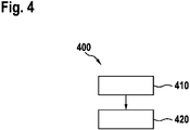
- Fig. 4 shows a flowchart of a method 400 of controlling a brake system according to an embodiment of the present invention.
- the method 400 is executable in connection with the brake system as described with reference to one of the preceding figures or a similar brake system.
- the method 400 can be executed in connection with a brake system for a vehicle.
- a brake system comprises a first electric power supply unit, an electronic brake control unit, wherein the electronic brake control unit is connected to the first electric power supply unit, a first axle pressure modulator for service brake chambers associated with a first axle of the vehicle, wherein the first axle pressure modulator is connected to the electronic brake control unit, a second axle pressure modulator for spring brake cylinders associated with a second axle of the vehicle, wherein the second axle pressure modulator is connected to the electronic brake control unit, a second electric power supply unit, an electronic parking brake controller, wherein the electronic parking brake controller is connected to the second electric power supply unit, wherein the electronic parking brake controller is fluidically connected to the spring brake cylinders, and a pressure modulator unit, wherein the pressure modulator unit is fluidically connected to the first axle pressure modulator, wherein the pressure modulator unit is connected to the electronic parking brake controller, wherein the electronic parking brake controller is configured to issue a control signal for controlling the pressure modulator unit, wherein
- the method 400 of controlling comprises a step 410 of receiving an error signal representing a malfunction of the first electric power supply unit or the electronic brake control unit or a malfunction of the second electric power supply unit, the electronic parking brake controller or the pressure modulator unit. Furthermore, the method 400 of controlling comprises a step 420 of transmitting service brake commands of the vehicle to the electronic parking brake controller in the event of a malfunction of the first electric power supply unit or the electronic brake control unit or to the electronic brake control unit in the event of a malfunction of the second electric power supply unit, the electronic parking brake controller or the pressure modulator unit.
- the electronic parking brake (EPB) controller 224 which may be standalone or integrated into any other pneumatic module, such as an air supply unit, is also used as a redundancy for brake actuation on axles equipped with spring brake actuators and on other axles without such actuators, which are controlled by using pressure modulator units, such as the pressure unit 234 and/or pressure modulator unit 335, actuating a backup port of the axle pressure modulator(s) concerned, such as the first axle pressure modulator 229.
- pressure modulator units such as the pressure unit 234 and/or pressure modulator unit 335
Priority Applications (4)
| Application Number | Priority Date | Filing Date | Title |
|---|---|---|---|
| EP18195165.8A EP3626557B1 (de) | 2018-09-18 | 2018-09-18 | Bremsensystem für ein fahrzeug |
| US17/272,682 US11787376B2 (en) | 2018-09-18 | 2019-08-29 | Brake system for a vehicle |
| PCT/EP2019/073133 WO2020057935A1 (en) | 2018-09-18 | 2019-08-29 | Brake system for a vehicle |
| CN201980061067.7A CN112714726B (zh) | 2018-09-18 | 2019-08-29 | 用于车辆的制动系统、车辆及控制制动系统的方法 |
Applications Claiming Priority (1)
| Application Number | Priority Date | Filing Date | Title |
|---|---|---|---|
| EP18195165.8A EP3626557B1 (de) | 2018-09-18 | 2018-09-18 | Bremsensystem für ein fahrzeug |
Publications (2)
| Publication Number | Publication Date |
|---|---|
| EP3626557A1 true EP3626557A1 (de) | 2020-03-25 |
| EP3626557B1 EP3626557B1 (de) | 2023-04-12 |
Family
ID=63642711
Family Applications (1)
| Application Number | Title | Priority Date | Filing Date |
|---|---|---|---|
| EP18195165.8A Active EP3626557B1 (de) | 2018-09-18 | 2018-09-18 | Bremsensystem für ein fahrzeug |
Country Status (4)
| Country | Link |
|---|---|
| US (1) | US11787376B2 (de) |
| EP (1) | EP3626557B1 (de) |
| CN (1) | CN112714726B (de) |
| WO (1) | WO2020057935A1 (de) |
Cited By (3)
| Publication number | Priority date | Publication date | Assignee | Title |
|---|---|---|---|---|
| SE2050645A1 (en) * | 2020-06-04 | 2021-12-05 | Scania Cv Ab | A redundant electro-pneumatic brake control system and method for redundant brake control of a vehicle |
| CN114701472A (zh) * | 2021-12-27 | 2022-07-05 | 瀚德万安(上海)电控制动系统有限公司 | 电控制动系统 |
| CN114987422A (zh) * | 2022-06-30 | 2022-09-02 | 徐州徐工矿业机械有限公司 | 一种矿用自卸车驻车制动冗余控制系统和方法 |
Families Citing this family (4)
| Publication number | Priority date | Publication date | Assignee | Title |
|---|---|---|---|---|
| KR20210148633A (ko) * | 2020-06-01 | 2021-12-08 | 현대모비스 주식회사 | 전자식 유압 브레이크 장치 |
| JP7331797B2 (ja) * | 2020-07-08 | 2023-08-23 | トヨタ自動車株式会社 | 車両制御装置 |
| CN113139239B (zh) * | 2021-04-30 | 2022-08-09 | 重庆长安汽车股份有限公司 | 一种驻车推杆可靠性分析方法 |
| GB2612644A (en) * | 2021-11-09 | 2023-05-10 | Daimler Truck AG | A method for engaging a pneumatic parking brake of a parking brake system of a motor vehicle |
Citations (3)
| Publication number | Priority date | Publication date | Assignee | Title |
|---|---|---|---|---|
| EP1794368A1 (de) * | 2004-09-29 | 2007-06-13 | voestalpine Schienen GmbH | Fahrschiene für einen schienentrog |
| DE102008009043B3 (de) | 2008-02-14 | 2009-05-14 | Knorr-Bremse Systeme für Nutzfahrzeuge GmbH | Elektronisch geregeltes Bremssystem mit redundanter Steuerung der Bremsaktuatoren |
| DE102016005318A1 (de) * | 2016-05-02 | 2017-11-02 | Wabco Gmbh | Elektronisch steuerbares pneumatisches Bremssystem in einem Nutzfahrzeug sowie Verfahren zum elektronischen Steuern eines pneumatischen Bremssystems. |
Family Cites Families (15)
| Publication number | Priority date | Publication date | Assignee | Title |
|---|---|---|---|---|
| DE10320608B4 (de) | 2003-05-08 | 2005-08-11 | Knorr-Bremse Systeme für Nutzfahrzeuge GmbH | Bremsanlage für Fahrzeuge, insbesondere Nutzfahrzeuge mit mindestens zwei separaten elektronischen Bremssteuerkreisen |
| DE102004009469A1 (de) * | 2004-02-27 | 2005-09-15 | Daimlerchrysler Ag | Redundantes Bremssteuerungssystem für ein Fahrzeug |
| DE102004010743A1 (de) | 2004-03-05 | 2006-01-19 | Wabco Gmbh & Co.Ohg | Elektrisch gesteuerte pneumatische Bremsanlage für ein Fahrzeug |
| DE102007004758C5 (de) | 2007-01-31 | 2016-07-21 | Knorr-Bremse Systeme für Nutzfahrzeuge GmbH | Bremsanlage und Verfahren zum Steuern einer Bremsanlage für ein Nutzfahrzeug |
| GB0705789D0 (en) | 2007-03-26 | 2007-05-02 | Haldex Brake Products Ltd | Vehicle braking system |
| DE102008003379A1 (de) | 2008-01-07 | 2009-07-09 | Wabco Gmbh | Bremsanlage für ein Fahrzeug sowie Bremspedaleinrichtung für eine derartige Bremsanlage |
| DE102008014458A1 (de) * | 2008-03-14 | 2009-09-17 | Wabco Gmbh | Bremsanlage für ein Fahrzeug |
| DE102010021909A1 (de) | 2010-05-28 | 2011-12-01 | Knorr-Bremse Systeme für Nutzfahrzeuge GmbH | Verfahren zur Steuerung einer Bremsanlage eines Fahrzeugs mit elektronisch geregeltem Hinterachsbremskreis und pneumatisch gesteuertem Vorderachsbremskreis |
| WO2013093545A1 (en) | 2011-12-23 | 2013-06-27 | Renault Trucks | Electronically controlled pneumatic brake system for an automotive vehicle and automotive vehicle equipped with such a system |
| DE102015121950A1 (de) * | 2015-12-16 | 2017-06-22 | Knorr-Bremse Systeme für Nutzfahrzeuge GmbH | Verfahren zum Steuern einer elektro-pneumatischen Parkbremseinrichtung eines Fahrzeugs während der Fahrt als Hilfsbremse |
| DE102017002719A1 (de) | 2017-03-21 | 2018-09-27 | Wabco Gmbh | Elektronisch steuerbares Bremssystem sowie Verfahren zum Steuern des elektronisch steuerbaren Bremssystems |
| DE102017002718A1 (de) | 2017-03-21 | 2018-09-27 | Wabco Gmbh | Elektronisch steuerbares Bremssystem sowie Verfahren zum Steuern des elektronisch steuerbaren Bremssystems |
| DE102017006356A1 (de) | 2017-03-21 | 2018-09-27 | Wabco Gmbh | Elektro-Pneumatische Handbremse (EPH) mit integriertem TCV (Europäische Ansteuerung) |
| EP3626562B1 (de) * | 2018-09-18 | 2022-10-26 | KNORR-BREMSE Systeme für Nutzfahrzeuge GmbH | Bremsensystem für ein fahrzeug und verfahren für den betrieb des bremsensystems eines fahrzeugs |
| DE102019106274A1 (de) * | 2019-03-12 | 2020-09-17 | Wabco Gmbh | Elektronisch steuerbares Bremssystem mit zwei Rückfallebenen (alternative Ausführung) |
-
2018
- 2018-09-18 EP EP18195165.8A patent/EP3626557B1/de active Active
-
2019
- 2019-08-29 US US17/272,682 patent/US11787376B2/en active Active
- 2019-08-29 CN CN201980061067.7A patent/CN112714726B/zh active Active
- 2019-08-29 WO PCT/EP2019/073133 patent/WO2020057935A1/en active Application Filing
Patent Citations (3)
| Publication number | Priority date | Publication date | Assignee | Title |
|---|---|---|---|---|
| EP1794368A1 (de) * | 2004-09-29 | 2007-06-13 | voestalpine Schienen GmbH | Fahrschiene für einen schienentrog |
| DE102008009043B3 (de) | 2008-02-14 | 2009-05-14 | Knorr-Bremse Systeme für Nutzfahrzeuge GmbH | Elektronisch geregeltes Bremssystem mit redundanter Steuerung der Bremsaktuatoren |
| DE102016005318A1 (de) * | 2016-05-02 | 2017-11-02 | Wabco Gmbh | Elektronisch steuerbares pneumatisches Bremssystem in einem Nutzfahrzeug sowie Verfahren zum elektronischen Steuern eines pneumatischen Bremssystems. |
Cited By (6)
| Publication number | Priority date | Publication date | Assignee | Title |
|---|---|---|---|---|
| SE2050645A1 (en) * | 2020-06-04 | 2021-12-05 | Scania Cv Ab | A redundant electro-pneumatic brake control system and method for redundant brake control of a vehicle |
| WO2021246930A1 (en) * | 2020-06-04 | 2021-12-09 | Scania Cv Ab | A redundant electro-pneumatic brake control system and method for redundant brake control of a vehicle |
| SE544621C2 (en) * | 2020-06-04 | 2022-09-27 | Scania Cv Ab | A redundant electro-pneumatic brake control system and method for redundant brake control of a vehicle |
| CN114701472A (zh) * | 2021-12-27 | 2022-07-05 | 瀚德万安(上海)电控制动系统有限公司 | 电控制动系统 |
| CN114987422A (zh) * | 2022-06-30 | 2022-09-02 | 徐州徐工矿业机械有限公司 | 一种矿用自卸车驻车制动冗余控制系统和方法 |
| CN114987422B (zh) * | 2022-06-30 | 2023-09-19 | 徐州徐工矿业机械有限公司 | 一种矿用自卸车驻车制动冗余控制系统和方法 |
Also Published As
| Publication number | Publication date |
|---|---|
| WO2020057935A1 (en) | 2020-03-26 |
| CN112714726B (zh) | 2023-04-25 |
| EP3626557B1 (de) | 2023-04-12 |
| CN112714726A (zh) | 2021-04-27 |
| US11787376B2 (en) | 2023-10-17 |
| US20210339725A1 (en) | 2021-11-04 |
Similar Documents
| Publication | Publication Date | Title |
|---|---|---|
| EP3626557B1 (de) | Bremsensystem für ein fahrzeug | |
| EP3626562B1 (de) | Bremsensystem für ein fahrzeug und verfahren für den betrieb des bremsensystems eines fahrzeugs | |
| US11872977B2 (en) | Brake system for a vehicle, vehicle and method of controlling a brake system for a vehicle | |
| US20200148180A1 (en) | Electronically controllable brake system and method of electronically controlling the brake system | |
| KR102310690B1 (ko) | 차량 브레이크 시스템 | |
| US20230406272A1 (en) | Electric system for a vehicle | |
| US20220297652A1 (en) | Electrically controllable pneumatic brake system having a two-channel pressure modulator system | |
| US20210323523A1 (en) | Brake system for a vehicle | |
| CN112739590B (zh) | 用于自动驾驶车辆的冗余制动系统 | |
| EP3626558B1 (de) | Bremsensystem für ein fahrzeug |
Legal Events
| Date | Code | Title | Description |
|---|---|---|---|
| PUAI | Public reference made under article 153(3) epc to a published international application that has entered the european phase |
Free format text: ORIGINAL CODE: 0009012 |
|
| STAA | Information on the status of an ep patent application or granted ep patent |
Free format text: STATUS: REQUEST FOR EXAMINATION WAS MADE |
|
| 17P | Request for examination filed |
Effective date: 20180918 |
|
| AK | Designated contracting states |
Kind code of ref document: A1 Designated state(s): AL AT BE BG CH CY CZ DE DK EE ES FI FR GB GR HR HU IE IS IT LI LT LU LV MC MK MT NL NO PL PT RO RS SE SI SK SM TR |
|
| AX | Request for extension of the european patent |
Extension state: BA ME |
|
| RBV | Designated contracting states (corrected) |
Designated state(s): AL AT BE BG CH CY CZ DE DK EE ES FI FR GB GR HR HU IE IS IT LI LT LU LV MC MK MT NL NO PL PT RO RS SE SI SK SM TR |
|
| GRAP | Despatch of communication of intention to grant a patent |
Free format text: ORIGINAL CODE: EPIDOSNIGR1 |
|
| STAA | Information on the status of an ep patent application or granted ep patent |
Free format text: STATUS: GRANT OF PATENT IS INTENDED |
|
| INTG | Intention to grant announced |
Effective date: 20221220 |
|
| GRAS | Grant fee paid |
Free format text: ORIGINAL CODE: EPIDOSNIGR3 |
|
| GRAA | (expected) grant |
Free format text: ORIGINAL CODE: 0009210 |
|
| STAA | Information on the status of an ep patent application or granted ep patent |
Free format text: STATUS: THE PATENT HAS BEEN GRANTED |
|
| AK | Designated contracting states |
Kind code of ref document: B1 Designated state(s): AL AT BE BG CH CY CZ DE DK EE ES FI FR GB GR HR HU IE IS IT LI LT LU LV MC MK MT NL NO PL PT RO RS SE SI SK SM TR |
|
| REG | Reference to a national code |
Ref country code: GB Ref legal event code: FG4D |
|
| REG | Reference to a national code |
Ref country code: CH Ref legal event code: EP |
|
| REG | Reference to a national code |
Ref country code: DE Ref legal event code: R096 Ref document number: 602018048264 Country of ref document: DE |
|
| REG | Reference to a national code |
Ref country code: IE Ref legal event code: FG4D |
|
| REG | Reference to a national code |
Ref country code: AT Ref legal event code: REF Ref document number: 1559613 Country of ref document: AT Kind code of ref document: T Effective date: 20230515 |
|
| REG | Reference to a national code |
Ref country code: SE Ref legal event code: TRGR |
|
| REG | Reference to a national code |
Ref country code: LT Ref legal event code: MG9D |
|
| REG | Reference to a national code |
Ref country code: NL Ref legal event code: MP Effective date: 20230412 |
|
| REG | Reference to a national code |
Ref country code: AT Ref legal event code: MK05 Ref document number: 1559613 Country of ref document: AT Kind code of ref document: T Effective date: 20230412 |
|
| PG25 | Lapsed in a contracting state [announced via postgrant information from national office to epo] |
Ref country code: NL Free format text: LAPSE BECAUSE OF FAILURE TO SUBMIT A TRANSLATION OF THE DESCRIPTION OR TO PAY THE FEE WITHIN THE PRESCRIBED TIME-LIMIT Effective date: 20230412 |
|
| PG25 | Lapsed in a contracting state [announced via postgrant information from national office to epo] |
Ref country code: PT Free format text: LAPSE BECAUSE OF FAILURE TO SUBMIT A TRANSLATION OF THE DESCRIPTION OR TO PAY THE FEE WITHIN THE PRESCRIBED TIME-LIMIT Effective date: 20230814 Ref country code: NO Free format text: LAPSE BECAUSE OF FAILURE TO SUBMIT A TRANSLATION OF THE DESCRIPTION OR TO PAY THE FEE WITHIN THE PRESCRIBED TIME-LIMIT Effective date: 20230712 Ref country code: ES Free format text: LAPSE BECAUSE OF FAILURE TO SUBMIT A TRANSLATION OF THE DESCRIPTION OR TO PAY THE FEE WITHIN THE PRESCRIBED TIME-LIMIT Effective date: 20230412 Ref country code: AT Free format text: LAPSE BECAUSE OF FAILURE TO SUBMIT A TRANSLATION OF THE DESCRIPTION OR TO PAY THE FEE WITHIN THE PRESCRIBED TIME-LIMIT Effective date: 20230412 |
|
| PG25 | Lapsed in a contracting state [announced via postgrant information from national office to epo] |
Ref country code: RS Free format text: LAPSE BECAUSE OF FAILURE TO SUBMIT A TRANSLATION OF THE DESCRIPTION OR TO PAY THE FEE WITHIN THE PRESCRIBED TIME-LIMIT Effective date: 20230412 Ref country code: PL Free format text: LAPSE BECAUSE OF FAILURE TO SUBMIT A TRANSLATION OF THE DESCRIPTION OR TO PAY THE FEE WITHIN THE PRESCRIBED TIME-LIMIT Effective date: 20230412 Ref country code: LV Free format text: LAPSE BECAUSE OF FAILURE TO SUBMIT A TRANSLATION OF THE DESCRIPTION OR TO PAY THE FEE WITHIN THE PRESCRIBED TIME-LIMIT Effective date: 20230412 Ref country code: LT Free format text: LAPSE BECAUSE OF FAILURE TO SUBMIT A TRANSLATION OF THE DESCRIPTION OR TO PAY THE FEE WITHIN THE PRESCRIBED TIME-LIMIT Effective date: 20230412 Ref country code: IS Free format text: LAPSE BECAUSE OF FAILURE TO SUBMIT A TRANSLATION OF THE DESCRIPTION OR TO PAY THE FEE WITHIN THE PRESCRIBED TIME-LIMIT Effective date: 20230812 Ref country code: HR Free format text: LAPSE BECAUSE OF FAILURE TO SUBMIT A TRANSLATION OF THE DESCRIPTION OR TO PAY THE FEE WITHIN THE PRESCRIBED TIME-LIMIT Effective date: 20230412 Ref country code: GR Free format text: LAPSE BECAUSE OF FAILURE TO SUBMIT A TRANSLATION OF THE DESCRIPTION OR TO PAY THE FEE WITHIN THE PRESCRIBED TIME-LIMIT Effective date: 20230713 Ref country code: AL Free format text: LAPSE BECAUSE OF FAILURE TO SUBMIT A TRANSLATION OF THE DESCRIPTION OR TO PAY THE FEE WITHIN THE PRESCRIBED TIME-LIMIT Effective date: 20230412 |
|
| PGFP | Annual fee paid to national office [announced via postgrant information from national office to epo] |
Ref country code: SE Payment date: 20230921 Year of fee payment: 6 Ref country code: DE Payment date: 20230919 Year of fee payment: 6 |
|
| PG25 | Lapsed in a contracting state [announced via postgrant information from national office to epo] |
Ref country code: FI Free format text: LAPSE BECAUSE OF FAILURE TO SUBMIT A TRANSLATION OF THE DESCRIPTION OR TO PAY THE FEE WITHIN THE PRESCRIBED TIME-LIMIT Effective date: 20230412 |
|
| REG | Reference to a national code |
Ref country code: DE Ref legal event code: R026 Ref document number: 602018048264 Country of ref document: DE |
|
| PG25 | Lapsed in a contracting state [announced via postgrant information from national office to epo] |
Ref country code: SK Free format text: LAPSE BECAUSE OF FAILURE TO SUBMIT A TRANSLATION OF THE DESCRIPTION OR TO PAY THE FEE WITHIN THE PRESCRIBED TIME-LIMIT Effective date: 20230412 |
|
| PLBI | Opposition filed |
Free format text: ORIGINAL CODE: 0009260 |
|
| PLAX | Notice of opposition and request to file observation + time limit sent |
Free format text: ORIGINAL CODE: EPIDOSNOBS2 |
|
| PG25 | Lapsed in a contracting state [announced via postgrant information from national office to epo] |
Ref country code: SM Free format text: LAPSE BECAUSE OF FAILURE TO SUBMIT A TRANSLATION OF THE DESCRIPTION OR TO PAY THE FEE WITHIN THE PRESCRIBED TIME-LIMIT Effective date: 20230412 Ref country code: SK Free format text: LAPSE BECAUSE OF FAILURE TO SUBMIT A TRANSLATION OF THE DESCRIPTION OR TO PAY THE FEE WITHIN THE PRESCRIBED TIME-LIMIT Effective date: 20230412 Ref country code: RO Free format text: LAPSE BECAUSE OF FAILURE TO SUBMIT A TRANSLATION OF THE DESCRIPTION OR TO PAY THE FEE WITHIN THE PRESCRIBED TIME-LIMIT Effective date: 20230412 Ref country code: EE Free format text: LAPSE BECAUSE OF FAILURE TO SUBMIT A TRANSLATION OF THE DESCRIPTION OR TO PAY THE FEE WITHIN THE PRESCRIBED TIME-LIMIT Effective date: 20230412 Ref country code: DK Free format text: LAPSE BECAUSE OF FAILURE TO SUBMIT A TRANSLATION OF THE DESCRIPTION OR TO PAY THE FEE WITHIN THE PRESCRIBED TIME-LIMIT Effective date: 20230412 Ref country code: CZ Free format text: LAPSE BECAUSE OF FAILURE TO SUBMIT A TRANSLATION OF THE DESCRIPTION OR TO PAY THE FEE WITHIN THE PRESCRIBED TIME-LIMIT Effective date: 20230412 |
|
| 26 | Opposition filed |
Opponent name: ZF CV SYSTEMS GLOBAL GMBH Effective date: 20240112 |
|
| P01 | Opt-out of the competence of the unified patent court (upc) registered |
Effective date: 20240125 |
|
| REG | Reference to a national code |
Ref country code: CH Ref legal event code: PL |
|
| PG25 | Lapsed in a contracting state [announced via postgrant information from national office to epo] |
Ref country code: SI Free format text: LAPSE BECAUSE OF FAILURE TO SUBMIT A TRANSLATION OF THE DESCRIPTION OR TO PAY THE FEE WITHIN THE PRESCRIBED TIME-LIMIT Effective date: 20230412 |