EP3626562B1 - Bremsensystem für ein fahrzeug und verfahren für den betrieb des bremsensystems eines fahrzeugs - Google Patents
Bremsensystem für ein fahrzeug und verfahren für den betrieb des bremsensystems eines fahrzeugs Download PDFInfo
- Publication number
- EP3626562B1 EP3626562B1 EP18195182.3A EP18195182A EP3626562B1 EP 3626562 B1 EP3626562 B1 EP 3626562B1 EP 18195182 A EP18195182 A EP 18195182A EP 3626562 B1 EP3626562 B1 EP 3626562B1
- Authority
- EP
- European Patent Office
- Prior art keywords
- brake
- control
- electronic
- axle
- pressure
- Prior art date
- Legal status (The legal status is an assumption and is not a legal conclusion. Google has not performed a legal analysis and makes no representation as to the accuracy of the status listed.)
- Active
Links
- 238000000034 method Methods 0.000 title claims description 14
- 230000007257 malfunction Effects 0.000 claims description 23
- 230000003213 activating effect Effects 0.000 claims description 13
- 238000004891 communication Methods 0.000 description 12
- 230000004044 response Effects 0.000 description 4
- 238000012544 monitoring process Methods 0.000 description 3
- 230000004913 activation Effects 0.000 description 2
- 238000000926 separation method Methods 0.000 description 2
- 238000005516 engineering process Methods 0.000 description 1
- 230000036541 health Effects 0.000 description 1
- 230000003993 interaction Effects 0.000 description 1
- 230000001960 triggered effect Effects 0.000 description 1
Images


Classifications
-
- B—PERFORMING OPERATIONS; TRANSPORTING
- B60—VEHICLES IN GENERAL
- B60T—VEHICLE BRAKE CONTROL SYSTEMS OR PARTS THEREOF; BRAKE CONTROL SYSTEMS OR PARTS THEREOF, IN GENERAL; ARRANGEMENT OF BRAKING ELEMENTS ON VEHICLES IN GENERAL; PORTABLE DEVICES FOR PREVENTING UNWANTED MOVEMENT OF VEHICLES; VEHICLE MODIFICATIONS TO FACILITATE COOLING OF BRAKES
- B60T8/00—Arrangements for adjusting wheel-braking force to meet varying vehicular or ground-surface conditions, e.g. limiting or varying distribution of braking force
- B60T8/32—Arrangements for adjusting wheel-braking force to meet varying vehicular or ground-surface conditions, e.g. limiting or varying distribution of braking force responsive to a speed condition, e.g. acceleration or deceleration
- B60T8/88—Arrangements for adjusting wheel-braking force to meet varying vehicular or ground-surface conditions, e.g. limiting or varying distribution of braking force responsive to a speed condition, e.g. acceleration or deceleration with failure responsive means, i.e. means for detecting and indicating faulty operation of the speed responsive control means
- B60T8/92—Arrangements for adjusting wheel-braking force to meet varying vehicular or ground-surface conditions, e.g. limiting or varying distribution of braking force responsive to a speed condition, e.g. acceleration or deceleration with failure responsive means, i.e. means for detecting and indicating faulty operation of the speed responsive control means automatically taking corrective action
- B60T8/94—Arrangements for adjusting wheel-braking force to meet varying vehicular or ground-surface conditions, e.g. limiting or varying distribution of braking force responsive to a speed condition, e.g. acceleration or deceleration with failure responsive means, i.e. means for detecting and indicating faulty operation of the speed responsive control means automatically taking corrective action on a fluid pressure regulator
-
- B—PERFORMING OPERATIONS; TRANSPORTING
- B60—VEHICLES IN GENERAL
- B60T—VEHICLE BRAKE CONTROL SYSTEMS OR PARTS THEREOF; BRAKE CONTROL SYSTEMS OR PARTS THEREOF, IN GENERAL; ARRANGEMENT OF BRAKING ELEMENTS ON VEHICLES IN GENERAL; PORTABLE DEVICES FOR PREVENTING UNWANTED MOVEMENT OF VEHICLES; VEHICLE MODIFICATIONS TO FACILITATE COOLING OF BRAKES
- B60T13/00—Transmitting braking action from initiating means to ultimate brake actuator with power assistance or drive; Brake systems incorporating such transmitting means, e.g. air-pressure brake systems
- B60T13/10—Transmitting braking action from initiating means to ultimate brake actuator with power assistance or drive; Brake systems incorporating such transmitting means, e.g. air-pressure brake systems with fluid assistance, drive, or release
- B60T13/58—Combined or convertible systems
- B60T13/581—Combined or convertible systems both hydraulic and pneumatic
-
- B—PERFORMING OPERATIONS; TRANSPORTING
- B60—VEHICLES IN GENERAL
- B60T—VEHICLE BRAKE CONTROL SYSTEMS OR PARTS THEREOF; BRAKE CONTROL SYSTEMS OR PARTS THEREOF, IN GENERAL; ARRANGEMENT OF BRAKING ELEMENTS ON VEHICLES IN GENERAL; PORTABLE DEVICES FOR PREVENTING UNWANTED MOVEMENT OF VEHICLES; VEHICLE MODIFICATIONS TO FACILITATE COOLING OF BRAKES
- B60T13/00—Transmitting braking action from initiating means to ultimate brake actuator with power assistance or drive; Brake systems incorporating such transmitting means, e.g. air-pressure brake systems
- B60T13/10—Transmitting braking action from initiating means to ultimate brake actuator with power assistance or drive; Brake systems incorporating such transmitting means, e.g. air-pressure brake systems with fluid assistance, drive, or release
- B60T13/66—Electrical control in fluid-pressure brake systems
- B60T13/68—Electrical control in fluid-pressure brake systems by electrically-controlled valves
- B60T13/683—Electrical control in fluid-pressure brake systems by electrically-controlled valves in pneumatic systems or parts thereof
-
- B—PERFORMING OPERATIONS; TRANSPORTING
- B60—VEHICLES IN GENERAL
- B60T—VEHICLE BRAKE CONTROL SYSTEMS OR PARTS THEREOF; BRAKE CONTROL SYSTEMS OR PARTS THEREOF, IN GENERAL; ARRANGEMENT OF BRAKING ELEMENTS ON VEHICLES IN GENERAL; PORTABLE DEVICES FOR PREVENTING UNWANTED MOVEMENT OF VEHICLES; VEHICLE MODIFICATIONS TO FACILITATE COOLING OF BRAKES
- B60T13/00—Transmitting braking action from initiating means to ultimate brake actuator with power assistance or drive; Brake systems incorporating such transmitting means, e.g. air-pressure brake systems
- B60T13/10—Transmitting braking action from initiating means to ultimate brake actuator with power assistance or drive; Brake systems incorporating such transmitting means, e.g. air-pressure brake systems with fluid assistance, drive, or release
- B60T13/66—Electrical control in fluid-pressure brake systems
- B60T13/68—Electrical control in fluid-pressure brake systems by electrically-controlled valves
- B60T13/686—Electrical control in fluid-pressure brake systems by electrically-controlled valves in hydraulic systems or parts thereof
-
- B—PERFORMING OPERATIONS; TRANSPORTING
- B60—VEHICLES IN GENERAL
- B60T—VEHICLE BRAKE CONTROL SYSTEMS OR PARTS THEREOF; BRAKE CONTROL SYSTEMS OR PARTS THEREOF, IN GENERAL; ARRANGEMENT OF BRAKING ELEMENTS ON VEHICLES IN GENERAL; PORTABLE DEVICES FOR PREVENTING UNWANTED MOVEMENT OF VEHICLES; VEHICLE MODIFICATIONS TO FACILITATE COOLING OF BRAKES
- B60T7/00—Brake-action initiating means
- B60T7/02—Brake-action initiating means for personal initiation
-
- B—PERFORMING OPERATIONS; TRANSPORTING
- B60—VEHICLES IN GENERAL
- B60T—VEHICLE BRAKE CONTROL SYSTEMS OR PARTS THEREOF; BRAKE CONTROL SYSTEMS OR PARTS THEREOF, IN GENERAL; ARRANGEMENT OF BRAKING ELEMENTS ON VEHICLES IN GENERAL; PORTABLE DEVICES FOR PREVENTING UNWANTED MOVEMENT OF VEHICLES; VEHICLE MODIFICATIONS TO FACILITATE COOLING OF BRAKES
- B60T8/00—Arrangements for adjusting wheel-braking force to meet varying vehicular or ground-surface conditions, e.g. limiting or varying distribution of braking force
- B60T8/17—Using electrical or electronic regulation means to control braking
- B60T8/1701—Braking or traction control means specially adapted for particular types of vehicles
-
- B—PERFORMING OPERATIONS; TRANSPORTING
- B60—VEHICLES IN GENERAL
- B60T—VEHICLE BRAKE CONTROL SYSTEMS OR PARTS THEREOF; BRAKE CONTROL SYSTEMS OR PARTS THEREOF, IN GENERAL; ARRANGEMENT OF BRAKING ELEMENTS ON VEHICLES IN GENERAL; PORTABLE DEVICES FOR PREVENTING UNWANTED MOVEMENT OF VEHICLES; VEHICLE MODIFICATIONS TO FACILITATE COOLING OF BRAKES
- B60T2270/00—Further aspects of brake control systems not otherwise provided for
- B60T2270/10—ABS control systems
-
- B—PERFORMING OPERATIONS; TRANSPORTING
- B60—VEHICLES IN GENERAL
- B60T—VEHICLE BRAKE CONTROL SYSTEMS OR PARTS THEREOF; BRAKE CONTROL SYSTEMS OR PARTS THEREOF, IN GENERAL; ARRANGEMENT OF BRAKING ELEMENTS ON VEHICLES IN GENERAL; PORTABLE DEVICES FOR PREVENTING UNWANTED MOVEMENT OF VEHICLES; VEHICLE MODIFICATIONS TO FACILITATE COOLING OF BRAKES
- B60T2270/00—Further aspects of brake control systems not otherwise provided for
- B60T2270/40—Failsafe aspects of brake control systems
- B60T2270/402—Back-up
-
- B—PERFORMING OPERATIONS; TRANSPORTING
- B60—VEHICLES IN GENERAL
- B60T—VEHICLE BRAKE CONTROL SYSTEMS OR PARTS THEREOF; BRAKE CONTROL SYSTEMS OR PARTS THEREOF, IN GENERAL; ARRANGEMENT OF BRAKING ELEMENTS ON VEHICLES IN GENERAL; PORTABLE DEVICES FOR PREVENTING UNWANTED MOVEMENT OF VEHICLES; VEHICLE MODIFICATIONS TO FACILITATE COOLING OF BRAKES
- B60T2270/00—Further aspects of brake control systems not otherwise provided for
- B60T2270/40—Failsafe aspects of brake control systems
- B60T2270/403—Brake circuit failure
-
- B—PERFORMING OPERATIONS; TRANSPORTING
- B60—VEHICLES IN GENERAL
- B60T—VEHICLE BRAKE CONTROL SYSTEMS OR PARTS THEREOF; BRAKE CONTROL SYSTEMS OR PARTS THEREOF, IN GENERAL; ARRANGEMENT OF BRAKING ELEMENTS ON VEHICLES IN GENERAL; PORTABLE DEVICES FOR PREVENTING UNWANTED MOVEMENT OF VEHICLES; VEHICLE MODIFICATIONS TO FACILITATE COOLING OF BRAKES
- B60T2270/00—Further aspects of brake control systems not otherwise provided for
- B60T2270/40—Failsafe aspects of brake control systems
- B60T2270/413—Plausibility monitoring, cross check, redundancy
Definitions
- the present invention relates to a brake system for a vehicle, to a vehicle with said brake system, and to a method of controlling a brake system for a vehicle.
- WO 2004/098967A2 shows a braking system comprising at least two electric or electronic control braking circuits, galvanically isolated from each other.
- WO 2005/082694 A1 shows a brake control system for a utility vehicle, which comprises a service brake for breaking the wheels of the vehicle.
- the operational safety of a service brake is increased by equipping the service brake with an electronically controlled brake unit for every wheel for actuating the brake of the respective wheel.
- Two redundantly switched central control devices are interlinked with the brake units via control lines in such a manner as to control the brake units independently of each other.
- DE 10 2008 009 043 B3 shows a redundant brake system for a commercial vehicle.
- the system utilizes a parking brake integrated into an air supply unit as a redundant brake actuator.
- a control output of a trailer control module is used as pneumatic control input of axle modulators.
- EP 2 794 368 B1 shows a redundant brake system for a commercial vehicle.
- the system utilizes the parking brake integrated into an air supply unit as a redundant brake actuator.
- the air supply unit includes an additional electro-pneumatic modulator to generate control pressure for the pneumatic control input of the axle modulators.
- rEPM redundant electronic pressure modulator
- rEPBi redundant electronic parking brake
- the system may comprise a brake system with three independent electric brake control circuits, which can be necessary for autonomous driving case, where the vehicle should be able to proceed its mission even in case of a single failure.
- the priority between the redundant systems may be fixed, the first two redundant control circuits by the rEPM, and the third control circuit is provided by rEPBi.
- the switching between the redundant brake systems may be automated. In case of any malfunction the secondary or tertiary redundant brake system may be activated.
- independent pedal position sensors may be installed for all the three circuits to ensure the electric circuit separation of the different brake circuits.
- a brake system for a vehicle comprises:
- the vehicle may be a utility vehicle or commercial vehicle, for example a truck, bus or the like.
- the first axle may be a front axle and the second axle a rear axle of the vehicle.
- the service brake chambers and the spring brake cylinders may represent brake actuators of the brake system or the vehicle.
- the pressure modulators, the electronic brake control units and the electronic parking brake controller, also known as electronic parking brake module may be common units as already used in vehicles.
- the two electronic brake control units may be of identical type.
- the electronic brake control units and the electronic parking brake controller may be redundantly used to activate the service brake chambers and the spring brake cylinders in case of a service brake demand.
- the service brake demand may be different to a park brake demand being used to activate the brakes while the vehicle is in or close to a parking position.
- the service brake demand may be triggered by a driver of the vehicle or by an electronic control unit for an automated driving mode.
- the electronic parking brake controller may be used to activate the service brake chambers associated with the first axle additionally to the spring brake cylinders associated with the second axle in case of a service brake demand.
- the pneumatic signal issued by the electronic parking brake controller to the pressure modulator unit may be the second pneumatic control signal or a further pneumatic control signal.
- the electronic brake control unit may be part of a first control circuit, the further electronic brake control unit may be part of a second control circuit and the electronic parking brake controller may be part of a third control circuit.
- the first control circuit may be configured to provide a primary service brake functionality. If the brake system is intact, the electronic brake control may be used to activate the service brake chambers and the spring brake cylinders in case of a service brake demand. In the event of a malfunction of the first control circuit the second control circuit and/or the third second control circuit are configured to provide redundant service brake functionalities. In the event of a malfunction of the first control circuit the further electronic brake control unit or the electronic parking brake controller may be used to activate the service brake chambers and the spring brake cylinders in case of a service brake demand. Thus, one of the second and third control circuits may be selected to replace the first control circuit in case of a malfunction of the first control circuit in order to execute a service brake demand.
- the brake system may comprise a first electric power supply unit, which may be connected to the electronic brake control unit.
- the first electric power supply may be configured to provide electric power necessary to run the electronic brake control unit.
- the brake system may comprise a second power supply unit, which may be connected to the further electronic brake control unit.
- the second electric power supply may be configured to provide electric power necessary to run the further electronic brake control unit.
- the brake system may comprise a third power supply unit, which may be connected to the electronic brake control unit.
- the third electric power supply may be configured to provide electric power necessary to run the electronic brake control unit. Thus there may be three independent electric power supplies.
- the brake system may comprise a first switch being configured to select the first electric control signal or the further first electric control signal for controlling the first axle pressure modulator.
- the first switch may provide a switching functionality for switching between the first control circuit and the second control circuit with regard to the service brake chambers.
- the brake system may comprise a second switch being configured to select the second electric control signal or the further second electric control signal for controlling the second axle pressure modulator.
- the first switch may provide a switching functionality for switching between the first control circuit and the second control circuit with regard to the service brake chambers.
- the brake system may have an interface to sensors associated with the axels and/or wheels of the vehicle.
- the interface may be configured to provide sensor signals of the sensors to the first control circuit, the second control circuit and the third control circuit.
- the brake system may comprise at least one unit for branching the sensor signals received via the interface to the electronic brake control units and the electronic parking brake controller.
- the electronic parking brake controller and/or the pressure modulator unit is configured to receive at least one first sensor signal via an interface to at least one first sensor associated with the first axle.
- the at least sensor signal can be used to optimize an activation of the service brake chambers during a service brake demand carried out by the electronic parking brake controller.
- the pressure modulator unit may be an inverting relay valve. Such a valve is cost-efficient and reliable.
- the inverting relay valve may be used to convert the pneumatic signal, in particular the second pneumatic control signal, issued by the electronic parking brake controller.
- the pressure modulator unit may be an electrically controlled pressure modulator.
- the electronic parking brake controller may issue an electric signal for controlling the first axle pressure modulator via the pressure modulator unit.
- the electric signal may be issued by the electronic parking brake controller additionally to the second pneumatic control signal.
- the brake system may comprise a trailer control module for controlling braking functions of a trailer of the vehicle.
- the electronic brake control unit may be configured to issue a third electric control signal for controlling the trailer control module.
- the further electronic brake control unit may be configured to issue a further third electric control signal for controlling the trailer control module.
- the electronic parking brake controller may be configured to issue a third pneumatic control signal for controlling the trailer control module.
- the trailer control module may be common unit as already used in vehicles. If the brake system is intact, the electronic brake control may be used to control the trailer control module. In the event of a malfunction of the first control circuit the further electronic brake control or the electronic parking brake controller may be used to control the trailer control module.
- one of the second and third control circuits may be selected to replace the first control circuit in case of a malfunction of the first control circuit with regard to an activation of the brakes of a trailer.
- the brake system may comprise an human-machine interface being configured to issue at least one human-machine control signal for controlling the electronic brake control unit, the further electronic brake control unit and the electronic parking brake controller.
- the human-machine interface may be a foot brake sensor or a lever.
- the human-machine interface may be operated by a driver of the vehicle in order to slow down the vehicle. Even if both electronic brake control units are out of order, the brakes of the vehicle can still be activated by the electronic parking brake controller in order to slow down the vehicle.
- the brake system may comprise may comprise a control unit interface for connecting the electronic brake control unit, the further electronic brake control unit and the electronic parking brake controller to an electronic control unit.
- the brakes of the vehicle can be activated in response to a service brake demand issued by the electronic control unit, even if both electronic brake control units are out of order.
- the electronic brake control unit, the further electronic brake control unit and the electronic parking brake controller are pairwise interlinked with each other. This allows exchanging information between the control circuits, for example information concerning a malfunction detected in one of the control circuits.
- the brake system may comprise a left pressure control valve and a right pressure control valve.
- the left pressure control valve may be configured to control a pressure of a left pneumatic pressure signal provided by the first axle pressure modulator for activating a left service brake chamber associated with a left wheel of the first axle of the vehicle.
- the right pressure control valve may be configured to control a pressure of a right pneumatic pressure signal provided by the first axle pressure modulator for activating a right service brake chamber associated with a right wheel of the first axle of the vehicle.
- the electronic brake control unit may be configured to issue a left electric control signal for controlling the left pressure control valve and a right electric control signal for controlling the right pressure control valve.
- a redundant steering system can be realized.
- the autonomous driving has special demand against the steering system of an autonomous vehicle also.
- the intact steering system must be supplied with a redundant steering system, which requirement can be fulfilled by a special function of the brake system, namely the steer by braking.
- the brake system may comprise a further left pressure control valve and a further right pressure control valve.
- the further left pressure control valve may be configured to further control a further pressure of a left pneumatic pressure signal provided by the first axle pressure modulator for activating the left service brake chamber associated with the left wheel of the first axle of the vehicle.
- the further right pressure control valve may be configured to further control a pressure of the right pneumatic pressure signal provided by the first axle pressure modulator for activating the right service brake chamber associated with the right wheel of the first axle of the vehicle.
- the further electronic brake control unit may be configured to issue a further left electric control signal for controlling the further left pressure control valve and a further right electric control signal for controlling the further right pressure control valve.
- the brake system or the vehicle may comprise a steering gear unit.
- the steering gear unit and the electronic brake control units may be connected to different electric power supply units.
- a vehicle comprises:
- the brake system may be used instead of a common brake system used for vehicles.
- a method of controlling a brake system for a vehicle comprises the following steps:
- the method or the steps of the method may be executed using a controller.
- the method may be executed to control an embodiment of the aforementioned brake system.
- Fig. 1 shows a schematic illustration of a vehicle 100 comprising a brake system 102 according to an embodiment of the present invention.
- the vehicle 100 is a utility vehicle or commercial vehicle, such as a truck.
- the vehicle 100 comprises a first axle 104, in particular a front axle, and at least one second axle 106, in particular a rear axle, according to this embodiment.
- the first axle 104 comprises a left wheel 108 and a right wheel 110.
- the brake system 102 comprises a first control circuit 112, a second control circuit 114 and a third control circuit 116.
- the first control circuit 112 is used to activate the brakes of the vehicle 100 in response to a service brake demand.
- the second control circuit 114 or the third control circuit 116 are used to activate the brakes of the vehicle in response to the service brake demand instead of the first control circuit 112.
- the third control circuit 116 is used to activate the brakes of the vehicle in response to the service brake demand.
- the vehicle 100 comprises an electronic control unit 118 (ECU) for controlling speed and optionally driving direction of the vehicle 100.
- the electronic control unit 118 may be connected to the control circuits 112, 114, 116 via a control unit interface, like a CAN-bus.
- the electronic control unit 118 is configured to provide a service brake demand signal 120.
- the electronic control unit 118 is configured to provide the service brake demand signal 120 to the first control circuit 112.
- the electronic control unit 118 is configured to provide the service brake demand signal 120 to the second control circuit 114 or the third control circuit 116, when an error signal 122 indicates a malfunction of the first control circuit 112.
- the electronic control unit 118 is configured to provide a switch signal 124, when the error signal 122 indicates a malfunction of the first control circuit 112, wherein the switch signal 124 is configured to switch from the first control circuit 112 to the second control circuit 114.
- the switch signal 124 is provided to a control input of a switch for switching between electric control signals provides by the first control circuit 112 and the second control circuit 114.
- the control unit 118 may be part of the brake system 102.
- the electronic control unit 118 is configured to provide the service brake demand while the vehicle is in a full or partial autonomous operation mode. In this case the control circuits 112, 114, 116 can be automatically operated without an interaction of a driver of the vehicle.
- the brake system 102 comprises a monitoring unit for monitoring a state of health of the brake system 102 and in particular of the first control circuit 112.
- the monitoring unit is configured to provide the error signal 122.
- the vehicle 100 comprises a steering gear unit 126 for steering the vehicle 100, for example by controlling a steering box assembly of the vehicle 100.
- the electronic control unit 118 is configured to control the steering gear unit 126 in order to control the driving direction of the vehicle 100.
- the electronic control unit 118 is configured to provide a steering demand, for example a steering signal 128.
- the steering signal 128 is used by one of the circuits 112, 114, 116 to control the driving direction by activating the brakes of the vehicle 100.
- the steering signal 128 is used by the first control circuit 112 to control the driving and is used by the second control circuit 114 to control the driving direction in case of a malfunction of the first control circuit 112.
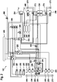
- Fig. 2 shows a schematic illustration of a brake system 102 according to an embodiment of the present invention.
- the brake system 102 corresponds or is similar to the brake system shown in Fig. 1 .
- the brake system 102 comprises a first electric power supply unit 201, a second electric power supply unit 202, and a third electric power supply unit 203.
- the brake system 102 further comprises an electronic brake control unit 220, a further electronic brake control unit 222 and an electronic parking brake controller 224, a first axle pressure modulator 228, a second axle pressure modulator 230, a left service brake chamber 232, a right service brake chamber 234, a left pressure control valve 236, a further left pressure control valve 237, a right pressure control valve 238, a further right pressure control valve 239 and two spring brake cylinders 240.
- the brake system 110 further comprises a first compressed air supply module 242, a second compressed air supply module 244 and a third compressed air supply module 246.
- the brake system 110 further comprises a pressure modulator unit 248, a first switch 250 and a second switch 252.
- the brake system 110 optionally comprises a trailer control module 254.
- the trailer control module 254 is configured to control braking functions of a trailer coupled to the vehicle.
- the trailer control module 254 is connected to the first compressed air supply module 242.
- the first electric power supply unit 201 and the electronic brake control unit 220 form part of the first control circuit
- the second electric power supply unit 202 and the further electronic brake control unit 222 form part of the second control circuit
- the third electric power supply unit 203 and the electronic parking brake controller 224 form part of the third control circuit described with reference to Fig. 1 .
- the first electric power supply unit 201 is electrically connected to the electronic brake control unit 220 via an analogous electric supply line.
- the second electric power supply unit 202 is electrically connected to the further electronic brake control unit 222 via a further analogous electric supply line.
- the third electric power supply unit 203 is electrically connected to the electronic parking brake controller 224 via a further analogous electric supply line.
- the electronic brake control unit 220 is electrically connected to the first axle pressure modulator 228 via a digital electric signal line and connected to the first switch 250 via an analogous electric signal or supply line. Furthermore, the electronic brake control unit 220 is electrically connected to the second axle pressure modulator 230 via a digital electric signal line and to the second switch 252 via an analogous electric signal or supply line. The electronic brake control unit 220 is configured to issue a first electric control signal for controlling the first axle pressure modulator 228 via the first switch 250 and a second electric control signal for controlling the second axle pressure modulator 230 via the second switch 252. According to an embodiment, the electronic brake control unit 220 is electrically connected to the trailer control module 228 via an analogous electric signal or supply line and to the electronic brake control unit 222 and the electronic parking brake controller 224 via digital electric signal lines.
- the electronic brake control unit 220 is electrically connected to the left pressure control valve 236 and the right pressure control valve 238 via two separate analogous electric signal or supply lines.
- the electronic brake control unit 220 is configured to issue a left electric control signal for controlling the left pressure control valve 236 and a right electric control signal for controlling the right pressure control valve 238.
- the electronic brake control unit 220 can be used to control the driving direction of the vehicle additionally to or instead of a steering gear unit of the vehicle.
- the steering gear unit and the electronic brake control unit 220 are connected to different electric power supply units 201, 202, 203.
- the further electronic brake control unit 222 is electrically connected to the first axle pressure modulator 228 via a digital electric signal line and connected to the first switch 250 via an analogous electric signal or supply line. Furthermore, the further electronic brake control unit 222 is electrically connected to the second axle pressure modulator 230 via a digital electric signal line and to the second switch 252 via an analogous electric signal or supply line. The further electronic brake control unit 222 is configured to issue a further first electric control signal for controlling the first axle pressure modulator 228 via the first switch 250 and a further second electric control signal for controlling the second axle pressure modulator 230 via the second switch 252. According to an embodiment, the further electronic brake control unit 220 is electrically connected to the trailer control module 228 via an analogous electric signal or supply line and to the electronic brake control unit 220 and to the electronic parking brake controller 224 via digital electric signal lines.
- the further electronic brake control unit 222 is electrically connected to the further left pressure control valve 237 and to the further right pressure control valve 239 via two separate analogous electric signal or supply lines.
- the further electronic brake control unit 222 is configured to issue a further left electric control signal for controlling the further left pressure control valve 237 and a further right electric control signal for controlling the further right pressure control valve 239.
- the further electronic brake control unit 222 can be used to control the driving direction of the vehicle additionally to or instead of the steering gear unit of the vehicle.
- the steering gear unit and the further electronic brake control unit 222 are connected to different electric power supply units 201, 202, 203.
- the first switch 250 comprises a first input, a second input and an output.
- the electronic brake control unit 220 is configured to issue the first electric control signal to the first input and the further electronic brake control unit 222 is configured to issue the further first electric control signal to the second input of the first switch 250.
- the output of the first switch 250 is connected to the first axle pressure modulator 228 via a common switched analogous electric signal or supply line.
- the first switch 250 is configured to select the first electric control signal or the further first electric control signal for controlling the first axle pressure modulator 228, for example responsive to a switch signal.
- the second switch 252 comprises a first input, a second input and an output.
- the electronic brake control unit 220 is configured to issue the second electric control signal to the first input and the further electronic brake control unit 222 is configured to issue the further second electric control signal to the second input of the second switch 252.
- the output of the second switch 252 is connected to the second axle pressure modulator 230 via a common switched analogous electric signal or supply line.
- the second switch 252 is configured to select the second electric control signal or the further second electric control signal for controlling the second axle pressure modulator 230, for example responsive to the switch signal.
- the first axle pressure modulator 228, the service brake chambers 232, 234 and the pressure control valves 236, 237, 238, 239 are associated with a first axle of the vehicle.
- the first axle pressure modulator 228 is fluidically connected to the third compressed air supply module 246 via a pneumatic supply line. Further the third compressed air supply module 246 is connected to the pressure modulator unit 248 via a pneumatic supply line
- the first axle pressure modulator 228 is fluidically connected to the left pressure control valve 236 via a pneumatic control line and to the right pressure control valve 238 via a further pneumatic control line.
- the left pressure control valve 236 is fluidically connected to the further left pressure control valve 237 via a pneumatic control line and the right pressure control valve 238 is fluidically connected to the further right pressure control valve 239 via a further pneumatic control line.
- the further left pressure control valve 237 is fluidically connected to the left service brake chamber 232 via a pneumatic control line and the further right pressure control valve 239 is fluidically connected to the right service brake chamber 234 via a further pneumatic control line.
- the second axle pressure modulator 230 and the spring brake cylinders 240 are associated with a second axle of the vehicle.
- the second axle pressure modulator 230 is fluidically connected to the second compressed air supply module 244 via a pneumatic supply line.
- the second axle pressure modulator 230 is fluidically connected to the spring brake cylinders 240 via pneumatic service brake control lines.
- the electronic parking brake controller 224 is electrically connected to the pressure modulator unit 248 via an analogous electric signal or supply line and a digital electrical signal line. According to an alternative embodiment, the electronic parking brake controller 224 is fluidically connected to the pressure modulator unit 248 via a pneumatic control line. The electronic parking brake controller 224 is fluidically connected to the spring brake cylinders 240 via a pneumatic control line. The electronic parking brake controller 224 is configured to issue a second pneumatic control signal for controlling the spring brake cylinders 240. Further, the electronic parking brake controller 224 is fluidically connected to the trailer control module 254 via a pneumatic brake control line.
- the pressure modulator unit 248 is connected to the first axle pressure modulator 228 via a pneumatic control line.
- the electronic parking brake controller 224 is configured to issue an electric signal to the pressure modulator unit 248.
- the pressure modulator unit 248 is configured to convert the electric signal issued by the electronic parking brake controller 224 into a first pneumatic control signal for controlling the first axle pressure modulator 228.
- the electronic brake control unit 220 is configured to issue a third electric control signal for controlling the trailer control module 254
- the further electronic brake control unit 222 is configured to issue a further third electric control signal for controlling the trailer control module 254
- the electronic parking brake controller 224 is configured to issue a third pneumatic control signal for controlling the trailer control module 254.
- the electronic parking brake controller 224 is electrically connected to a park brake lever sensor 256 via an analogous electric signal or supply line.
- the park brake lever sensor 256 can be operated by a driver of the vehicle in order to issue a park brake demand.
- the electronic parking brake controller 224 can be used to provide a park brake functionality and a service brake functionality.
- the brake system comprises a foot brake sensor 258.
- the foot brake sensor 258 is an human-machine interface which allows the driver to issue a service brake demand.
- the foot brake sensor 258 is connected to the electronic brake control unit 220 via a first analogous electric signal or supply line, to the further electronic brake control unit 222 via a second analogous electric signal or supply line, and to the electronic parking brake controller 224 via a third analogous electric signal or supply line.
- the foot brake sensor 258 is configured to issue a first human-machine control signal for controlling the electronic brake control unit 220, a second human-machine control signal for controlling the further electronic brake control unit 222 and a third human-machine control signal for controlling the electronic parking brake controller 224.
- the brake system comprises a control unit interface 260 for connecting the electronic brake control unit 220, the further electronic brake control unit 222 and the electronic parking brake controller 224 to an electronic control unit.
- the electronic brake control unit 220, the further electronic brake control unit 222 and the electronic parking brake controller 224 can be operated via the control unit interface 260 by an electronic control unit, for example during an automated driving mode, and additionally or alternatively by the foot brake sensor 258.
- the brake system 102 comprises a communication line selector 262.
- the electronic brake control unit 220 and the further electronic brake control unit 222 are connected via two separate digital electric signal lines to inputs of the communication line selector 262.
- An output of the communication line selector 262 is connected to a common electric signal line, for example to provide a signal according to ISO11992.
- the brake system 102 comprises a first sensor switch 264 and a second sensor switch 266.
- An input of the first sensor switch 264 is electrically connected to at least one first wheel sensor 268 associated to a left wheel of the first axle of the vehicle via an analogous electric signal or supply line.
- the first sensor switch 264 is configured to supply a first sensor signal issued by the first wheel sensor 268 to the first, second and third control circuit.
- a first output of the first sensor switch 264 is connected to the first axle pressure modulator 228 via at least one analogous electric line.
- the first axle pressure modulator 228 can be configured to use the first sensor signal forwarded by the first sensor switch 264 in order to control the pressure for activating the left service brake chamber 232 and/or to forward the first sensor signal to the electronic brake control unit 220 and the further electronic brake control unit 222.
- a second output of the first sensor switch 264 is connected to the pressure modulator unit 248 via at least one analogous electric line.
- the pressure modulator unit 248 can be configured to use the first sensor signal forwarded by the first sensor switch 264 in order to control the pressure provided to the first axle pressure modulator 228 and/or to forward the first sensor signal to the electronic parking brake controller 224.
- An input of the second sensor switch 266 is electrically connected to at least one second wheel sensor 270 associated to a right wheel of the first axle of the vehicle via an analogous electric signal or supply line.
- the second sensor switch 266 is configured to supply a second sensor signal issued by the second wheel sensor 270 to the first, second and third control circuit.
- a first output of the second sensor switch 266 is connected to the first axle pressure modulator 228 via at least one analogous electric line.
- the first axle pressure modulator 228 can be configured to use the second sensor signal forwarded by the second sensor switch 266 in order to control the pressure for activating the right service brake chamber 234 and/or to forward the second sensor signal to the electronic brake control unit 220 and the further electronic brake control unit 222.
- a second output of the second sensor switch 266 is connected to the pressure modulator unit 248 via at least one analogous electric line.
- the pressure modulator unit 248 can be configured to use the second sensor signal forwarded by the second sensor switch 266 in order to control the pressure provided to the first axle pressure modulator 228 and/or to forward the second sensor signal to the electronic parking brake controller 224.
- the brake system 102 comprises a third sensor switch 272 and a fourth sensor switch 274.
- An input of the third sensor switch 272 is electrically connected to at least one third wheel sensor 276 associated to a left wheel of the second axle of the vehicle via an analogous electric signal or supply line.
- the third sensor switch 272 is configured to supply a third sensor signal issued by the third wheel sensor 276 to the first, second and third control circuit.
- a first output of the third sensor switch 272 is connected to the second axle pressure modulator 230 via at least one analogous electric line.
- the second axle pressure modulator 230 can be configured to use the third sensor signal forwarded by the third sensor switch 272 in order to control the pressure for activating the left spring brake cylinder 240 and/or to forward the third sensor signal to the electronic brake control unit 220 and the further electronic brake control unit 222.
- a second output of the third sensor switch 272 is connected to the electronic parking brake controller 224 via at least one analogous electric line.
- An input of the fourth sensor switch 274 is electrically connected to at least one fourth wheel sensor 278 associated to a right wheel of the second axle of the vehicle via an analogous electric signal or supply line.
- the fourth sensor switch 274 is configured to supply a fourth sensor signal issued by the fourth wheel sensor 278 to the first, second and third control circuit.
- a first output of the fourth sensor switch 274 is connected to the second axle pressure modulator 230 via at least one analogous electric line.
- the second axle pressure modulator 230 can be configured to use the fourth sensor signal forwarded by the fourth sensor switch 274 in order to control the pressure for activating the right spring brake cylinder 240 and/or to forward the fourth sensor signal to the electronic brake control unit 220 and the further electronic brake control unit 222.
- a second output of the fourth sensor switch 274 is connected to the electronic parking brake controller 224 via at least one analogous electric line.
- each sensor switch 264, 266, 272, 274 is configured to forward a plurality of sensor signals.
- Fig. 2 shows a schematic of a redundant commercial vehicle electronic brake system 102 or electro-pneumatic brake system 102.
- the main components of the brake system 102 are described in the following.
- the first axle represents a front axle and the second axle represents a rear axle, thus “first” can be used as a synonym for "front” and “second” can be used as a synonym for "rear”.
- the priority between the redundant systems is fixed, the first two redundant control circuits by the electronic brake control units 220, 222 and the third control circuit is provided by the electronic parking brake controller 224.
- the switching between the redundant brake systems is automated. In case of any malfunction the secondary or tertiary redundant brake system is activated.
- independent pedal position sensors like sensors included in the foot brake sensor 258 are installed for all the three circuits to ensure the electric circuit separation of the different brake circuits.
- the brake system 102 is redundantly supplied by the power supply units 201, 202, 203 which are realized as separate batteries or power supplies or power sources.
- the EBS electronic brake control unit 220 is supplied from the first power supply unit 201.
- the electronic brake control unit 220 is electronically controlling the front axle pressure modulator 228, the pressure control valves 236, 238 on the front axle, the rear axle pressure modulator 230 and the trailer control module 254.
- the front axle wheel brakes are actuated by the service brake chambers 232, 234, while on the rear axle by spring brake cylinders 240 which are also known as spring brake combi cylinders.
- One of the redundant pair of the brake system 102 is provided by another EBS ECU, in particular the further electronic brake control unit 222, which is actuating the front axle pressure modulator 228 and the rear axle pressure modulator 230, for example via a second CAN channel.
- the further electronic brake control unit 222 provides an electric control signal to the trailer control module 254.
- the front axle There is a redundant pair of pressure control valves 236, 238, 237, 239 installed on the front axle to be able to use the steer-by-brake function with the redundant system of electronic brake control units.
- the possibility of the sidewise braking of the front axle ensures the vehicle stability e.g. on mu-split road surface during emergency braking.
- the signals of the wheel speed sensors 268, 270, 276, 278 can be routed by the electric communication line switches 264, 266, 272, 274 between the ECUs of the electronic brake control units 220, 222 and the electronic parking brake controller 224, which is necessary to perform ABS braking by the redundant EBS system 102 with any of the three control circuits.
- the other main redundant brake architecture part is the electronic parking brake, comprising the electronic parking brake controller 224, which provides the third control circuit.
- the brake control can be taken over by the EPB module, comprising the electronic parking brake controller 224, and the axles equipped by spring brake chambers 240 are actuated by the parking brake control, while other axles without spring brake chamber 240 are controlled pneumatically through the pressure modulator unit 248 and the first axle pressure modulator 228.
- the pressure modulator unit 248 can be an electrically controlled unit to the electronic parking brake controller, but in another realization in can be a pneumatic valve with an inverting relay function, which is using the output of the electronic parking brake controller 224 to control the axles without spring brakes 240, here the axles with service brake chambers 232.
- the electronic parking brake controller 224 or its power supply unit 203 has any malfunction the electronic brake control unit 220 is controlling the service brake system as in normal case.
- the parking brake modulation can be also temporally simulated in such a case by the service brake actuation.
- the foot brake sensor 258 provides three independent demand signals for the three different brake control circuits.
- the electronic control unit of each brake control circuit is able to receive external brake demand via an external communication line, like the control unit interface, from higher level vehicle systems, for example from an autonomous control logic, and all three electronic control units communicate with each other via internal communication line, for example for performing plausibility checks, etc.
- the control of the trailer is solved by the communication line switch 262 between the trailer and the two electronic brake control units 220, 222.
- the trailer control module 254 is controlled by the two electronic brake control units 220, 222 electrically; the electronic parking brake controller 224 can control the trailer via the inverting pneumatic port of the trailer control module 254, which is the state of the art.
- the brake system 102 further provides a redundant steering system.
- the primary and secondary circuits comprising the electronic brake control units 220, 222 can generate different pressures on each side on the front axle with the help of the pressure control valves 236, 237, 238, 239 based on a steering demand as a redundancy for a steering gear.
- the pressure difference between the left and the right side on the front axle causes a brake force difference sidewise, which causes a yaw-moment. Since the primary and secondary circuits comprising the electronic brake control units 220, 222 are powered from the first electric power supply unit 201 and the second electric power supply unit 202, therefore the steering gear electronics should be supplied from the third electric power supply unit 203.
- the steering gear electronics may correspond to the steering gear unit as shown in Fig. 1 .
- the brake system 102 of a commercial vehicle with an electro-pneumatic service brake system and an electro-pneumatic parking brake system comprises multiple redundancy, with control circuits more than two, in order that an automated vehicle can proceed its mission even in case of any single failure.
- the control circuits used for redundancy may be the second control circuit comprising the further electronic brake control unit 222 and the third control circuit comprising the electronic parking brake controller 224.
- the brake control pressure of two brake control circuits are controlled by the electronic brake control units 220, 222 with axle modulator 228, 230 branching, and the third control circuit is controlled by the electronic parking brake system comprising the electronic parking brake controller 224.
- the wheel sensors 168, 270, 276, 278 may comprise wheel-end sensors like wheel-speed sensors, wear sensors or any further sensor. According to an embodiment, the sensors 168, 270, 276, 278 are branched by an appropriate device, for example the switches 264, 266, 272, 274 for the brake control units comprising the electronic brake control units 220, 222 and the electronic parking brake controller 224.
- all three brake control circuits can be manually commanded by a three-circuit human-machine interface 258. Additionally or alternatively all three redundant brake control circuits can be actuated electronically via three independent circuit external electric communication lines, like CANs, which is indicated in Fig. 2 by the control unit interface 260.
- all redundant brake system controllers here the electronic brake control units 220, 222 and the electronic parking brake controller 224 are pairwise interlinked with each other, for example to perform plausibility checks.
- Fig. 3 shows a schematic illustration of a brake system 102 according to an embodiment of the present invention.
- the brake system 102 corresponds or is similar to the brake system shown in Fig. 2 with the difference that the electronic parking brake controller 224 is integrated in an electronic air control (EAC) 380.
- EAC electronic air control
- the electronic parking brake unit is integrated into an air supply unit.
- the electronic air control 380 is connected to the compressed air supply modules 242, 244, 246.
- Fig. 4 shows a flowchart of a method of controlling a brake system according to an embodiment of the present invention.
- the method 400 is executable in connection with a brake system as described with reference to one of the preceding figures or a similar brake system.
- the method comprises a step 401 of receiving an error signal representing a malfunction of a first control circuit comprising the electronic brake control of the brake system and a step 403 of transmitting a service brake demand signal to the further electronic brake control unit or the electronic parking brake controller of the brake system responsive to the error signal.
Claims (14)
- Bremssystem (102) für ein Fahrzeug (100), wobei das Bremssystem (102) umfasst:einen Druckmodulator der ersten Achse (228) für Betriebsbremskammern (232, 234), die einer ersten Achse (104) des Fahrzeugs (100) zugeordnet sind;einen Druckmodulator der zweiten Achse (230) für Federspeicherbremszylinder (240), die einer zweiten Achse (106) des Fahrzeugs (100) zugeordnet sind;eine elektronische Bremssteuereinheit (220), wobei die elektronische Bremssteuereinheit (220) ausgebildet ist, ein erstes elektrisches Steuersignal zum Steuern des Druckmodulators der ersten Achse (228) und ein zweites elektrisches Steuersignal zum Steuern des Druckmodulators der zweiten Achse (230) auszugeben;eine weitere elektronische Bremssteuereinheit (222), wobei die weitere elektronische Bremssteuereinheit (222) ausgebildet ist, ein weiteres erstes elektrisches Steuersignal zum Steuern des Druckmodulators der ersten Achse (228) und ein weiteres zweites elektrisches Steuersignal zum Steuern des Druckmodulators der zweiten Achse (230) auszugeben;gekennzeichnet durcheine elektronische Parkbremssteuereinheit (224), wobei die elektronische Parkbremssteuereinheit (224) ausgebildet ist, ein zweites pneumatisches Steuersignal zum Steuern der Federspeicherbremszylinder (240) auszugeben; undeine Druckmodulatoreinheit (248), wobei die Druckmodulatoreinheit (248) ausgebildet ist, ein pneumatisches Signal oder ein elektrisches Signal, das von der elektronischen Parkbremssteuereinheit (224) ausgegeben wird, in ein erstes pneumatisches Steuersignal zum Steuern des Druckmodulators der ersten Achse (228) umzuwandeln.
- Bremssystem (102) nach Anspruch 1, wobei die elektronische Bremssteuereinheit (220) Teil einer ersten Steuerschaltung (112) ist, die weitere elektronische Bremssteuereinheit (222) Teil einer zweiten Steuerschaltung (114) ist und die elektronische Parkbremssteuereinheit (224) Teil einer dritten Steuerschaltung (116) ist, wobei die erste Steuerschaltung (112) ausgebildet ist, eine primäre Betriebsbremsfunktionalität bereitzustellen und im Fall einer Fehlfunktion der ersten Steuerschaltung (112) die zweite Steuerschaltung (114) und/oder die dritte Steuerschaltung (116) ausgebildet sind, eine redundante Betriebsbremsfunktionalität bereitzustellen.
- Bremssystem (102) nach einem der vorstehenden Ansprüche, umfassend eine erste Stromversorgungseinheit (201), wobei die erste Stromversorgungseinheit (201) mit der elektronischen Bremssteuereinheit (220) verbunden ist, eine zweite Stromversorgungseinheit (202), wobei die zweite Stromversorgungseinheit (202) mit der weiteren elektronischen Bremssteuereinheit (222) verbunden ist, und eine dritte Stromversorgungseinheit (203), wobei die dritte Stromversorgungseinheit (203) mit der elektronischen Bremssteuereinheit (220) verbunden ist.
- Bremssystem (102) nach einem der vorstehenden Ansprüche, umfassend einen ersten Schalter (250), wobei der erste Schalter (250) ausgebildet ist, das erste elektrische Steuersignal oder das weitere erste elektrische Steuersignal zum Steuern des Druckmodulators der ersten Achse (228) zu wählen.
- Bremssystem (102) nach einem der vorstehenden Ansprüche, umfassend einen zweiten Schalter (252), wobei der zweite Schalter (252) ausgebildet ist, das zweite elektrische Steuersignal oder das weitere zweite elektrische Steuersignal zum Steuern des Druckmodulators der zweiten Achse (230) zu wählen.
- Bremssystem (102) nach einem der vorstehenden Ansprüche, wobei die elektronische Parkbremssteuereinheit (224) und/oder die Druckmodulatoreinheit (248) ausgebildet ist, zumindest ein erstes Sensorsignal über eine Schnittstelle mit zumindest einem ersten Sensor (268), der der ersten Achse (104) zugeordnet ist, zu empfangen.
- Bremssystem (102) nach einem der vorstehenden Ansprüche, wobei die Druckmodulatoreinheit (248) ein Inversrelaisventil oder ein elektrisch gesteuerter Druckmodulator ist.
- Bremssystem (102) nach einem der vorstehenden Ansprüche, umfassend ein Anhängersteuerungsmodul (254) zum Steuern von Bremsfunktionen eines Anhängers des Fahrzeugs, wobei die elektronische Bremssteuereinheit (220) ausgebildet ist, ein drittes elektrisches Steuersignal zum Steuern des Anhängersteuerungsmoduls (254) auszugeben, und wobei die weitere elektronische Bremssteuereinheit (222) ausgebildet ist, ein weiteres drittes elektrisches Steuersignal zum Steuern des Anhängersteuerungsmoduls (254) auszugeben, und wobei die elektronische Parkbremssteuereinheit (224) ausgebildet ist, ein drittes pneumatisches Steuersignal zum Steuern des Anhängersteuerungsmoduls (254) auszugeben.
- Bremssystem (102) nach einem der vorstehenden Ansprüche, umfassend eine Mensch-Maschine-Schnittstelle (258), wobei die Mensch-Maschine-Schnittstelle (258) ausgebildet ist, zumindest ein Mensch-Maschine-Steuersignal zum Steuern der elektronischen Bremssteuereinheit (220), der weiteren elektronischen Bremssteuereinheit (222) und der elektronischen Parkbremssteuereinheit (224) auszugeben.
- Bremssystem (102) nach einem der vorstehenden Ansprüche, umfassend eine Steuereinheitsschnittstelle (260) zum Verbinden der elektronischen Bremssteuereinheit (220), der weiteren elektronischen Bremssteuereinheit (222) und der elektronischen Parkbremssteuereinheit (224) mit einer elektronischen Steuereinheit (118).
- Bremssystem (102) nach einem der vorstehenden Ansprüche, wobei die elektronische Bremssteuereinheit (220), die weitere elektronische Bremssteuereinheit (222) und die elektronische Parkbremssteuereinheit (224) paarweise miteinander vernetzt sind.
- Bremssystem (102) nach einem der vorstehenden Ansprüche, umfassend ein linkes Drucksteuerventil (236) und ein rechtes Drucksteuerventil (238), wobei das linke Drucksteuerventil (236) ausgebildet ist, einen Druck eines linken pneumatischen Drucksignals zu steuern, das von dem Druckmodulator der ersten Achse (228) zum Aktivieren einer linken Betriebsbremskammer (232), die einem linken Rad der ersten Achse (104) des Fahrzeugs (100) zugeordnet ist, bereitgestellt wird, und wobei das rechte Drucksteuerventil (238) ausgebildet ist, einen Druck eines rechten pneumatischen Drucksignals zu steuern, das von dem Druckmodulator der ersten Achse (228) zum Aktivieren einer rechten Betriebsbremskammer (234), die einem rechten Rad der ersten Achse (104) des Fahrzeugs (100) zugeordnet ist, bereitgestellt wird, und weiter umfassend ein weiteres linkes Drucksteuerventil (237) und ein weiteres rechtes Drucksteuerventil (239), wobei das weitere linke Drucksteuerventil (237) ausgebildet ist, weiter den Druck des linken pneumatischen Drucksignals zu steuern, das von dem Druckmodulator der ersten Achse (228) zum Aktivieren einer linken Betriebsbremskammer (232), die dem linken Rad der ersten Achse (104) des Fahrzeugs (100) zugeordnet ist, bereitgestellt wird, und wobei das weitere rechte Drucksteuerventil (238) ausgebildet ist, weiter einen Druck des rechten pneumatischen Drucksignals zu steuern, das von dem Druckmodulator der ersten Achse (228) zum Aktivieren der rechten Betriebsbremskammer (234), die dem rechten Rad der ersten Achse (104) des Fahrzeugs (100) zugeordnet ist, bereitgestellt wird, und wobei die elektronische Bremssteuereinheit (220) ausgebildet ist, ein linkes elektrisches Steuersignal zum Steuern des linken Drucksteuerventils (236) und ein rechtes elektrisches Steuersignal zum Steuern des rechten Drucksteuerventils (238) auszugeben und wobei die weitere elektronische Bremssteuereinheit (222) ausgebildet ist, ein weiteres linkes elektrisches Steuersignal zum Steuern des weiteren linken Drucksteuerventils (237) und ein weiteres rechtes elektrisches Steuersignal zum Steuern des weiteren rechten Drucksteuerventils (239) auszugeben.
- Fahrzeug (100), wobei das Fahrzeug (100) umfasst:eine erste Achse (104) und eine zweite Achse (106);Betriebsbremskammern (232, 234), die der ersten Achse (104) zugeordnet sind;Federspeicherbremszylinder (240), die der zweiten Achse (106) zugeordnet sind; undein Bremssystem (102) nach einem der vorstehenden Ansprüche.
- Verfahren zum Steuern eines Bremssystems (102) für ein Fahrzeug (100), wobei das Bremssystem (102) ein Bremssystem (102) nach einem der Ansprüche 1 bis 12 ist, wobei das Verfahren umfasst:Empfangen (401) eines Fehlersignals (122), das eine Fehlfunktion der ersten Steuerschaltung (112), die die elektronische Bremssteuereinheit (220) umfasst, darstellt; undÜbertragen (403) eines Betriebsbremsbedarfssignals (120) an die weitere elektronische Bremssteuereinheit (222) oder die elektronische Parkbremssteuereinheit (224) in Reaktion auf das Fehlersignal (122).
Priority Applications (4)
| Application Number | Priority Date | Filing Date | Title |
|---|---|---|---|
| EP18195182.3A EP3626562B1 (de) | 2018-09-18 | 2018-09-18 | Bremsensystem für ein fahrzeug und verfahren für den betrieb des bremsensystems eines fahrzeugs |
| CN201980061107.8A CN112739591B (zh) | 2018-09-18 | 2019-09-03 | 用于车辆的制动系统、车辆和控制车辆的制动系统的方法 |
| US17/273,043 US20210323522A1 (en) | 2018-09-18 | 2019-09-03 | Brake system for a vehicle, vehicle and method of controlling a brake system for a vehicle |
| PCT/EP2019/073457 WO2020057964A1 (en) | 2018-09-18 | 2019-09-03 | Brake system for a vehicle, vehicle and method of controlling a brake system for a vehicle |
Applications Claiming Priority (1)
| Application Number | Priority Date | Filing Date | Title |
|---|---|---|---|
| EP18195182.3A EP3626562B1 (de) | 2018-09-18 | 2018-09-18 | Bremsensystem für ein fahrzeug und verfahren für den betrieb des bremsensystems eines fahrzeugs |
Publications (2)
| Publication Number | Publication Date |
|---|---|
| EP3626562A1 EP3626562A1 (de) | 2020-03-25 |
| EP3626562B1 true EP3626562B1 (de) | 2022-10-26 |
Family
ID=63642721
Family Applications (1)
| Application Number | Title | Priority Date | Filing Date |
|---|---|---|---|
| EP18195182.3A Active EP3626562B1 (de) | 2018-09-18 | 2018-09-18 | Bremsensystem für ein fahrzeug und verfahren für den betrieb des bremsensystems eines fahrzeugs |
Country Status (4)
| Country | Link |
|---|---|
| US (1) | US20210323522A1 (de) |
| EP (1) | EP3626562B1 (de) |
| CN (1) | CN112739591B (de) |
| WO (1) | WO2020057964A1 (de) |
Families Citing this family (8)
| Publication number | Priority date | Publication date | Assignee | Title |
|---|---|---|---|---|
| DE102017002721A1 (de) * | 2017-03-21 | 2018-09-27 | Wabco Gmbh | Elektronisch steuerbares Bremssystem sowie Verfahren zum Steuern des elektronisch steuerbaren Bremssystems mit rein elektrischem Bremswertgeber |
| EP3626560B1 (de) * | 2018-09-18 | 2022-10-26 | KNORR-BREMSE Systeme für Nutzfahrzeuge GmbH | Bremsensystem für ein fahrzeug und fahrzeug |
| EP3626557B1 (de) * | 2018-09-18 | 2023-04-12 | KNORR-BREMSE Systeme für Nutzfahrzeuge GmbH | Bremsensystem für ein fahrzeug |
| DE102019106591A1 (de) | 2019-03-15 | 2020-09-17 | Wabco Gmbh | Elektronisch steuerbares Bremssystem mit zwei Rückfallebenen |
| JP7200829B2 (ja) * | 2019-06-03 | 2023-01-10 | トヨタ自動車株式会社 | 車両システム |
| DE202019106881U1 (de) * | 2019-12-10 | 2021-03-11 | Haldex Brake Products Aktiebolag | Bremsanlage eines Nutzfahrzeugs |
| SE544621C2 (en) * | 2020-06-04 | 2022-09-27 | Scania Cv Ab | A redundant electro-pneumatic brake control system and method for redundant brake control of a vehicle |
| DE102022103806A1 (de) * | 2022-02-17 | 2023-08-17 | Audi Aktiengesellschaft | Bremssystemaufbau und Fahrzeug mit einem Bremssystemaufbau |
Family Cites Families (15)
| Publication number | Priority date | Publication date | Assignee | Title |
|---|---|---|---|---|
| DE10132493C2 (de) * | 2001-07-05 | 2003-05-15 | Knorr Bremse Systeme | Druckmittelbetätigte Bremsanlage einer Zugfahrzeug-Anhänger-Kombination |
| DE10320608B4 (de) * | 2003-05-08 | 2005-08-11 | Knorr-Bremse Systeme für Nutzfahrzeuge GmbH | Bremsanlage für Fahrzeuge, insbesondere Nutzfahrzeuge mit mindestens zwei separaten elektronischen Bremssteuerkreisen |
| DE102004009469A1 (de) * | 2004-02-27 | 2005-09-15 | Daimlerchrysler Ag | Redundantes Bremssteuerungssystem für ein Fahrzeug |
| DE102005043608B4 (de) * | 2005-09-06 | 2008-01-17 | Knorr-Bremse Systeme für Nutzfahrzeuge GmbH | Verfahren zum Steuern einer pneumatischen Bremsanlage |
| DE102005062907B3 (de) * | 2005-12-29 | 2007-05-10 | Knorr-Bremse Systeme für Nutzfahrzeuge GmbH | Druckmittelbetätigtes Bremssystem mit redundanter Steuerung der Bremsaktuatoren |
| DE102008003379A1 (de) * | 2008-01-07 | 2009-07-09 | Wabco Gmbh | Bremsanlage für ein Fahrzeug sowie Bremspedaleinrichtung für eine derartige Bremsanlage |
| CN101918258B (zh) * | 2008-01-22 | 2013-06-19 | 沃尔沃建筑设备公司 | 用于使车辆制动的方法和系统 |
| DE102008009043B3 (de) | 2008-02-14 | 2009-05-14 | Knorr-Bremse Systeme für Nutzfahrzeuge GmbH | Elektronisch geregeltes Bremssystem mit redundanter Steuerung der Bremsaktuatoren |
| EP2794368B2 (de) | 2011-12-23 | 2021-11-17 | Renault Trucks | Elektronisch gesteuertes pneumatisches bremssystem für ein automobil und automobil mit einem solchen system |
| DE102013007881A1 (de) * | 2013-05-08 | 2014-11-13 | Knorr-Bremse Systeme für Nutzfahrzeuge GmbH | Verfahren zur Abbremsung einer Zugfahrzeug-Anhängerkombination mit reduzierter Anhängerbremskraft abhängig vom Ansprechen des Zugfahrzeug-ABS |
| EP2821303B1 (de) * | 2013-07-05 | 2016-09-14 | KNORR-BREMSE Systeme für Nutzfahrzeuge GmbH | Elektropneumatische Feststellbremse |
| CN103419765B (zh) * | 2013-08-30 | 2015-11-18 | 长城汽车股份有限公司 | 车辆及用于车辆的自动驻车系统 |
| EP3509922B1 (de) * | 2016-09-08 | 2021-11-10 | KNORR-BREMSE Systeme für Nutzfahrzeuge GmbH | Elektrisches system für ein fahrzeug |
| US20180170331A1 (en) * | 2016-12-20 | 2018-06-21 | GM Global Technology Operations LLC | Vehicle braking mode for competitive driving |
| DE102017002718A1 (de) * | 2017-03-21 | 2018-09-27 | Wabco Gmbh | Elektronisch steuerbares Bremssystem sowie Verfahren zum Steuern des elektronisch steuerbaren Bremssystems |
-
2018
- 2018-09-18 EP EP18195182.3A patent/EP3626562B1/de active Active
-
2019
- 2019-09-03 WO PCT/EP2019/073457 patent/WO2020057964A1/en active Application Filing
- 2019-09-03 US US17/273,043 patent/US20210323522A1/en active Pending
- 2019-09-03 CN CN201980061107.8A patent/CN112739591B/zh active Active
Also Published As
| Publication number | Publication date |
|---|---|
| WO2020057964A1 (en) | 2020-03-26 |
| US20210323522A1 (en) | 2021-10-21 |
| CN112739591A (zh) | 2021-04-30 |
| EP3626562A1 (de) | 2020-03-25 |
| CN112739591B (zh) | 2023-03-28 |
Similar Documents
| Publication | Publication Date | Title |
|---|---|---|
| EP3626562B1 (de) | Bremsensystem für ein fahrzeug und verfahren für den betrieb des bremsensystems eines fahrzeugs | |
| EP3626557B1 (de) | Bremsensystem für ein fahrzeug | |
| EP3626560B1 (de) | Bremsensystem für ein fahrzeug und fahrzeug | |
| US8838354B2 (en) | Combined braking system, particularly for motor vehicles | |
| CN113544026A (zh) | 具有两个后备等级(替代设计)的能电子控制的制动系统 | |
| EP3415386B1 (de) | Fahrzeugbremssystem | |
| EP3626559B1 (de) | Bremsensystem für ein fahrzeug | |
| US20220297652A1 (en) | Electrically controllable pneumatic brake system having a two-channel pressure modulator system | |
| US11807203B2 (en) | Redundant brake system for an autonomously driven vehicle | |
| EP3822134B1 (de) | Bremssystem für ein kraftfahrzeug und anhängersteuerungsmodul | |
| US11926302B2 (en) | Electronically controlled pneumatic brake system with two single-channel axle modulators and abs valves, and vehicle having a brake system of this type | |
| EP3626558B1 (de) | Bremsensystem für ein fahrzeug |
Legal Events
| Date | Code | Title | Description |
|---|---|---|---|
| PUAI | Public reference made under article 153(3) epc to a published international application that has entered the european phase |
Free format text: ORIGINAL CODE: 0009012 |
|
| STAA | Information on the status of an ep patent application or granted ep patent |
Free format text: STATUS: REQUEST FOR EXAMINATION WAS MADE |
|
| 17P | Request for examination filed |
Effective date: 20180918 |
|
| AK | Designated contracting states |
Kind code of ref document: A1 Designated state(s): AL AT BE BG CH CY CZ DE DK EE ES FI FR GB GR HR HU IE IS IT LI LT LU LV MC MK MT NL NO PL PT RO RS SE SI SK SM TR |
|
| AX | Request for extension of the european patent |
Extension state: BA ME |
|
| RBV | Designated contracting states (corrected) |
Designated state(s): AL AT BE BG CH CY CZ DE DK EE ES FI FR GB GR HR HU IE IS IT LI LT LU LV MC MK MT NL NO PL PT RO RS SE SI SK SM TR |
|
| GRAP | Despatch of communication of intention to grant a patent |
Free format text: ORIGINAL CODE: EPIDOSNIGR1 |
|
| STAA | Information on the status of an ep patent application or granted ep patent |
Free format text: STATUS: GRANT OF PATENT IS INTENDED |
|
| INTG | Intention to grant announced |
Effective date: 20220623 |
|
| GRAS | Grant fee paid |
Free format text: ORIGINAL CODE: EPIDOSNIGR3 |
|
| GRAA | (expected) grant |
Free format text: ORIGINAL CODE: 0009210 |
|
| STAA | Information on the status of an ep patent application or granted ep patent |
Free format text: STATUS: THE PATENT HAS BEEN GRANTED |
|
| AK | Designated contracting states |
Kind code of ref document: B1 Designated state(s): AL AT BE BG CH CY CZ DE DK EE ES FI FR GB GR HR HU IE IS IT LI LT LU LV MC MK MT NL NO PL PT RO RS SE SI SK SM TR |
|
| REG | Reference to a national code |
Ref country code: GB Ref legal event code: FG4D |
|
| REG | Reference to a national code |
Ref country code: CH Ref legal event code: EP |
|
| REG | Reference to a national code |
Ref country code: DE Ref legal event code: R096 Ref document number: 602018042175 Country of ref document: DE |
|
| REG | Reference to a national code |
Ref country code: AT Ref legal event code: REF Ref document number: 1526844 Country of ref document: AT Kind code of ref document: T Effective date: 20221115 |
|
| REG | Reference to a national code |
Ref country code: IE Ref legal event code: FG4D |
|
| REG | Reference to a national code |
Ref country code: LT Ref legal event code: MG9D |
|
| REG | Reference to a national code |
Ref country code: NL Ref legal event code: MP Effective date: 20221026 |
|
| REG | Reference to a national code |
Ref country code: AT Ref legal event code: MK05 Ref document number: 1526844 Country of ref document: AT Kind code of ref document: T Effective date: 20221026 |
|
| PG25 | Lapsed in a contracting state [announced via postgrant information from national office to epo] |
Ref country code: NL Free format text: LAPSE BECAUSE OF FAILURE TO SUBMIT A TRANSLATION OF THE DESCRIPTION OR TO PAY THE FEE WITHIN THE PRESCRIBED TIME-LIMIT Effective date: 20221026 |
|
| PG25 | Lapsed in a contracting state [announced via postgrant information from national office to epo] |
Ref country code: SE Free format text: LAPSE BECAUSE OF FAILURE TO SUBMIT A TRANSLATION OF THE DESCRIPTION OR TO PAY THE FEE WITHIN THE PRESCRIBED TIME-LIMIT Effective date: 20221026 Ref country code: PT Free format text: LAPSE BECAUSE OF FAILURE TO SUBMIT A TRANSLATION OF THE DESCRIPTION OR TO PAY THE FEE WITHIN THE PRESCRIBED TIME-LIMIT Effective date: 20230227 Ref country code: NO Free format text: LAPSE BECAUSE OF FAILURE TO SUBMIT A TRANSLATION OF THE DESCRIPTION OR TO PAY THE FEE WITHIN THE PRESCRIBED TIME-LIMIT Effective date: 20230126 Ref country code: LT Free format text: LAPSE BECAUSE OF FAILURE TO SUBMIT A TRANSLATION OF THE DESCRIPTION OR TO PAY THE FEE WITHIN THE PRESCRIBED TIME-LIMIT Effective date: 20221026 Ref country code: FI Free format text: LAPSE BECAUSE OF FAILURE TO SUBMIT A TRANSLATION OF THE DESCRIPTION OR TO PAY THE FEE WITHIN THE PRESCRIBED TIME-LIMIT Effective date: 20221026 Ref country code: ES Free format text: LAPSE BECAUSE OF FAILURE TO SUBMIT A TRANSLATION OF THE DESCRIPTION OR TO PAY THE FEE WITHIN THE PRESCRIBED TIME-LIMIT Effective date: 20221026 Ref country code: AT Free format text: LAPSE BECAUSE OF FAILURE TO SUBMIT A TRANSLATION OF THE DESCRIPTION OR TO PAY THE FEE WITHIN THE PRESCRIBED TIME-LIMIT Effective date: 20221026 |
|
| PG25 | Lapsed in a contracting state [announced via postgrant information from national office to epo] |
Ref country code: RS Free format text: LAPSE BECAUSE OF FAILURE TO SUBMIT A TRANSLATION OF THE DESCRIPTION OR TO PAY THE FEE WITHIN THE PRESCRIBED TIME-LIMIT Effective date: 20221026 Ref country code: PL Free format text: LAPSE BECAUSE OF FAILURE TO SUBMIT A TRANSLATION OF THE DESCRIPTION OR TO PAY THE FEE WITHIN THE PRESCRIBED TIME-LIMIT Effective date: 20221026 Ref country code: LV Free format text: LAPSE BECAUSE OF FAILURE TO SUBMIT A TRANSLATION OF THE DESCRIPTION OR TO PAY THE FEE WITHIN THE PRESCRIBED TIME-LIMIT Effective date: 20221026 Ref country code: IS Free format text: LAPSE BECAUSE OF FAILURE TO SUBMIT A TRANSLATION OF THE DESCRIPTION OR TO PAY THE FEE WITHIN THE PRESCRIBED TIME-LIMIT Effective date: 20230226 Ref country code: HR Free format text: LAPSE BECAUSE OF FAILURE TO SUBMIT A TRANSLATION OF THE DESCRIPTION OR TO PAY THE FEE WITHIN THE PRESCRIBED TIME-LIMIT Effective date: 20221026 Ref country code: GR Free format text: LAPSE BECAUSE OF FAILURE TO SUBMIT A TRANSLATION OF THE DESCRIPTION OR TO PAY THE FEE WITHIN THE PRESCRIBED TIME-LIMIT Effective date: 20230127 |
|
| P01 | Opt-out of the competence of the unified patent court (upc) registered |
Effective date: 20230508 |
|
| REG | Reference to a national code |
Ref country code: DE Ref legal event code: R097 Ref document number: 602018042175 Country of ref document: DE |
|
| PG25 | Lapsed in a contracting state [announced via postgrant information from national office to epo] |
Ref country code: SM Free format text: LAPSE BECAUSE OF FAILURE TO SUBMIT A TRANSLATION OF THE DESCRIPTION OR TO PAY THE FEE WITHIN THE PRESCRIBED TIME-LIMIT Effective date: 20221026 Ref country code: RO Free format text: LAPSE BECAUSE OF FAILURE TO SUBMIT A TRANSLATION OF THE DESCRIPTION OR TO PAY THE FEE WITHIN THE PRESCRIBED TIME-LIMIT Effective date: 20221026 Ref country code: EE Free format text: LAPSE BECAUSE OF FAILURE TO SUBMIT A TRANSLATION OF THE DESCRIPTION OR TO PAY THE FEE WITHIN THE PRESCRIBED TIME-LIMIT Effective date: 20221026 Ref country code: DK Free format text: LAPSE BECAUSE OF FAILURE TO SUBMIT A TRANSLATION OF THE DESCRIPTION OR TO PAY THE FEE WITHIN THE PRESCRIBED TIME-LIMIT Effective date: 20221026 Ref country code: CZ Free format text: LAPSE BECAUSE OF FAILURE TO SUBMIT A TRANSLATION OF THE DESCRIPTION OR TO PAY THE FEE WITHIN THE PRESCRIBED TIME-LIMIT Effective date: 20221026 |
|
| PG25 | Lapsed in a contracting state [announced via postgrant information from national office to epo] |
Ref country code: SK Free format text: LAPSE BECAUSE OF FAILURE TO SUBMIT A TRANSLATION OF THE DESCRIPTION OR TO PAY THE FEE WITHIN THE PRESCRIBED TIME-LIMIT Effective date: 20221026 Ref country code: AL Free format text: LAPSE BECAUSE OF FAILURE TO SUBMIT A TRANSLATION OF THE DESCRIPTION OR TO PAY THE FEE WITHIN THE PRESCRIBED TIME-LIMIT Effective date: 20221026 |
|
| PLBE | No opposition filed within time limit |
Free format text: ORIGINAL CODE: 0009261 |
|
| STAA | Information on the status of an ep patent application or granted ep patent |
Free format text: STATUS: NO OPPOSITION FILED WITHIN TIME LIMIT |
|
| 26N | No opposition filed |
Effective date: 20230727 |
|
| PG25 | Lapsed in a contracting state [announced via postgrant information from national office to epo] |
Ref country code: SI Free format text: LAPSE BECAUSE OF FAILURE TO SUBMIT A TRANSLATION OF THE DESCRIPTION OR TO PAY THE FEE WITHIN THE PRESCRIBED TIME-LIMIT Effective date: 20221026 |
|
| PGFP | Annual fee paid to national office [announced via postgrant information from national office to epo] |
Ref country code: DE Payment date: 20230919 Year of fee payment: 6 |