EP3626039B1 - Lageranordnung und landwirtschaftliche maschine mit dieser lageranordnung - Google Patents
Lageranordnung und landwirtschaftliche maschine mit dieser lageranordnung Download PDFInfo
- Publication number
- EP3626039B1 EP3626039B1 EP19401033.6A EP19401033A EP3626039B1 EP 3626039 B1 EP3626039 B1 EP 3626039B1 EP 19401033 A EP19401033 A EP 19401033A EP 3626039 B1 EP3626039 B1 EP 3626039B1
- Authority
- EP
- European Patent Office
- Prior art keywords
- bearing
- journal
- support frame
- housing
- designed
- Prior art date
- Legal status (The legal status is an assumption and is not a legal conclusion. Google has not performed a legal analysis and makes no representation as to the accuracy of the status listed.)
- Active
Links
Images


Classifications
-
- A—HUMAN NECESSITIES
- A01—AGRICULTURE; FORESTRY; ANIMAL HUSBANDRY; HUNTING; TRAPPING; FISHING
- A01B—SOIL WORKING IN AGRICULTURE OR FORESTRY; PARTS, DETAILS, OR ACCESSORIES OF AGRICULTURAL MACHINES OR IMPLEMENTS, IN GENERAL
- A01B71/00—Construction or arrangement of setting or adjusting mechanisms, of implement or tool drive or of power take-off; Means for protecting parts against dust, or the like; Adapting machine elements to or for agricultural purposes
- A01B71/04—Bearings of rotating parts, e.g. for soil-working discs
-
- A—HUMAN NECESSITIES
- A01—AGRICULTURE; FORESTRY; ANIMAL HUSBANDRY; HUNTING; TRAPPING; FISHING
- A01B—SOIL WORKING IN AGRICULTURE OR FORESTRY; PARTS, DETAILS, OR ACCESSORIES OF AGRICULTURAL MACHINES OR IMPLEMENTS, IN GENERAL
- A01B29/00—Rollers
- A01B29/04—Rollers with non-smooth surface formed of rotatably-mounted rings or discs or with projections or ribs on the roller body; Land packers
- A01B29/041—Rollers with non-smooth surface formed of rotatably-mounted rings or discs or with projections or ribs on the roller body; Land packers of "Cambridge"-type, i.e. the soil-pressing rings being stacked on a shaft
-
- F—MECHANICAL ENGINEERING; LIGHTING; HEATING; WEAPONS; BLASTING
- F16—ENGINEERING ELEMENTS AND UNITS; GENERAL MEASURES FOR PRODUCING AND MAINTAINING EFFECTIVE FUNCTIONING OF MACHINES OR INSTALLATIONS; THERMAL INSULATION IN GENERAL
- F16C—SHAFTS; FLEXIBLE SHAFTS; ELEMENTS OR CRANKSHAFT MECHANISMS; ROTARY BODIES OTHER THAN GEARING ELEMENTS; BEARINGS
- F16C19/00—Bearings with rolling contact, for exclusively rotary movement
- F16C19/22—Bearings with rolling contact, for exclusively rotary movement with bearing rollers essentially of the same size in one or more circular rows, e.g. needle bearings
- F16C19/34—Bearings with rolling contact, for exclusively rotary movement with bearing rollers essentially of the same size in one or more circular rows, e.g. needle bearings for both radial and axial load
- F16C19/38—Bearings with rolling contact, for exclusively rotary movement with bearing rollers essentially of the same size in one or more circular rows, e.g. needle bearings for both radial and axial load with two or more rows of rollers
- F16C19/383—Bearings with rolling contact, for exclusively rotary movement with bearing rollers essentially of the same size in one or more circular rows, e.g. needle bearings for both radial and axial load with two or more rows of rollers with tapered rollers, i.e. rollers having essentially the shape of a truncated cone
- F16C19/385—Bearings with rolling contact, for exclusively rotary movement with bearing rollers essentially of the same size in one or more circular rows, e.g. needle bearings for both radial and axial load with two or more rows of rollers with tapered rollers, i.e. rollers having essentially the shape of a truncated cone with two rows, i.e. double-row tapered roller bearings
- F16C19/386—Bearings with rolling contact, for exclusively rotary movement with bearing rollers essentially of the same size in one or more circular rows, e.g. needle bearings for both radial and axial load with two or more rows of rollers with tapered rollers, i.e. rollers having essentially the shape of a truncated cone with two rows, i.e. double-row tapered roller bearings in O-arrangement
-
- F—MECHANICAL ENGINEERING; LIGHTING; HEATING; WEAPONS; BLASTING
- F16—ENGINEERING ELEMENTS AND UNITS; GENERAL MEASURES FOR PRODUCING AND MAINTAINING EFFECTIVE FUNCTIONING OF MACHINES OR INSTALLATIONS; THERMAL INSULATION IN GENERAL
- F16C—SHAFTS; FLEXIBLE SHAFTS; ELEMENTS OR CRANKSHAFT MECHANISMS; ROTARY BODIES OTHER THAN GEARING ELEMENTS; BEARINGS
- F16C23/00—Bearings for exclusively rotary movement adjustable for aligning or positioning
- F16C23/06—Ball or roller bearings
- F16C23/08—Ball or roller bearings self-adjusting
- F16C23/082—Ball or roller bearings self-adjusting by means of at least one substantially spherical surface
- F16C23/084—Ball or roller bearings self-adjusting by means of at least one substantially spherical surface sliding on a complementary spherical surface
-
- F—MECHANICAL ENGINEERING; LIGHTING; HEATING; WEAPONS; BLASTING
- F16—ENGINEERING ELEMENTS AND UNITS; GENERAL MEASURES FOR PRODUCING AND MAINTAINING EFFECTIVE FUNCTIONING OF MACHINES OR INSTALLATIONS; THERMAL INSULATION IN GENERAL
- F16C—SHAFTS; FLEXIBLE SHAFTS; ELEMENTS OR CRANKSHAFT MECHANISMS; ROTARY BODIES OTHER THAN GEARING ELEMENTS; BEARINGS
- F16C27/00—Elastic or yielding bearings or bearing supports, for exclusively rotary movement
- F16C27/06—Elastic or yielding bearings or bearing supports, for exclusively rotary movement by means of parts of rubber or like materials
- F16C27/063—Sliding contact bearings
-
- F—MECHANICAL ENGINEERING; LIGHTING; HEATING; WEAPONS; BLASTING
- F16—ENGINEERING ELEMENTS AND UNITS; GENERAL MEASURES FOR PRODUCING AND MAINTAINING EFFECTIVE FUNCTIONING OF MACHINES OR INSTALLATIONS; THERMAL INSULATION IN GENERAL
- F16C—SHAFTS; FLEXIBLE SHAFTS; ELEMENTS OR CRANKSHAFT MECHANISMS; ROTARY BODIES OTHER THAN GEARING ELEMENTS; BEARINGS
- F16C33/00—Parts of bearings; Special methods for making bearings or parts thereof
- F16C33/72—Sealings
- F16C33/76—Sealings of ball or roller bearings
-
- F—MECHANICAL ENGINEERING; LIGHTING; HEATING; WEAPONS; BLASTING
- F16—ENGINEERING ELEMENTS AND UNITS; GENERAL MEASURES FOR PRODUCING AND MAINTAINING EFFECTIVE FUNCTIONING OF MACHINES OR INSTALLATIONS; THERMAL INSULATION IN GENERAL
- F16C—SHAFTS; FLEXIBLE SHAFTS; ELEMENTS OR CRANKSHAFT MECHANISMS; ROTARY BODIES OTHER THAN GEARING ELEMENTS; BEARINGS
- F16C2310/00—Agricultural machines
Definitions
- the invention relates to a bearing arrangement according to the preamble of patent claim 1 and an agricultural machine according to the preamble of patent claim 5.
- This agricultural machine includes a rotating element designed as a ground roller.
- a support frame is also assigned to the floor roller.
- the floor roller is rotatably connected to the support frame on both end sides by means of a bearing pin and a bearing unit.
- the ground roller can roll on the ground and rotate around the horizontal axis of rotation that runs transversely to the direction of travel.
- the bearing unit consists of a bearing arrangement with a single-row ball bearing, with both the bearing inner ring and the bearing outer ring having a special geometry and can thus be tilted in the bearing housing or against each other.
- the bearing unit can be arranged via the bearing housing either on the rotating element designed as a floor roller or on the support frame.
- the respective bearing pin which is rotatably mounted in the rolling bearing designed as a ball bearing, is therefore arranged either on the support frame or on the floor roller. In other words: it is irrelevant whether the bearing unit or the bearing pin is arranged on the ground roller and rotates with it when the field is being worked, while the other of the two components is arranged on the support frame.
- the bearing unit is set up using the specially shaped bearing rings to compensate for an angular offset between the longitudinal axes of the bearing housing and the bearing journal.
- the angular offset can arise, for example, from an arrangement of the bearing journal that is not at least approximately exact its longitudinal axis in an extension of the axis of rotation of the floor roller, an arrangement of the surface on the floor roller, which serves to fasten the bearing unit or the bearing pin, that is not at least approximately exactly orthogonal to the axis of rotation of the floor roller and/or an arrangement of the longitudinal axis of the support structure that is not at least approximately exactly orthogonal to the axis of rotation of the floor roller.
- Compensating for the angular misalignment has a positive effect on the service life of the bearing unit, as the bearing journal would otherwise carry out a wobbling movement that would damage the bearing unit when the floor roller rotates.
- a disadvantage of the bearing arrangement of the agricultural machine described above is that the bearing unit and in particular the rolling bearing arranged in the bearing housing are almost unprotected from external influences.
- dirt such as dust and plant residues are regularly stirred up, which can penetrate into the bearing housing.
- the dirt can settle in the bearing housing and thus prevent the rotatable bearing by means of the rolling elements and the possibility of compensating for defective angular misalignment. The penetration of foreign bodies into the bearing arrangement should therefore be prevented.
- the DE 10 2013 102 871 A1 also discloses a bearing arrangement for a floor roller, with a sealing ring being assigned to the bearing housing.
- a mechanical seal for pumps or rollers of agricultural equipment is from the DE 200 10 216 U1 known.
- a housing seal for the drive shaft of a powered tillage implement is disclosed.
- the object of the present invention is to create a bearing arrangement which has improved protection against external influences and environmental stresses.
- the bearing unit comprises a sealing arrangement, wherein the sealing arrangement is designed to seal a circumferential gap between the bearing journal and the bearing housing, preferably at least approximately liquid-tight and/or dust-tight.
- the invention makes use of the knowledge that the area in which relative movements between the bearing journal and the bearing housing occur is particularly susceptible to the contamination problems described above and the sealing of the same is therefore particularly beneficial for protecting the bearing arrangement.
- the sealing arrangement according to the invention not only prevents splash water from entering the bearing housing but also aims to prevent oil used as a lubricant from exiting the bearing housing.
- the bearing unit is expediently particularly developed for use on the rotating element designed as a floor roller.
- the bearing unit in its bearing housing comprises a rolling bearing for the rotatable connection between the floor roller and the support frame via the bearing journal, the rolling bearing being designed as a pendulum bearing with preferably barrel-shaped or spherical rolling bodies and the bearing unit being set up for this purpose by means of the pendulum bearing is to compensate for the angular misalignment.
- the rolling elements are preferably arranged between a bearing outer ring and a bearing inner ring.
- the bearing outer ring preferably has a concave raceway;
- the bearing inner ring preferably has two concave raceways inclined to the bearing axis.
- the bearing inner ring can be tilted via the rolling elements in the bearing outer ring that roll between the raceways.
- Self-aligning bearings also have particularly high load ratings in relation to the required installation space and are therefore suitable for a robust and space-saving design.
- the bearing housing is designed to be at least approximately oil-tight and/or dust-tight by means of the sealing arrangement which seals the circumferential gap between the bearing journal and the bearing housing and interacts with the bearing journal on the one hand and a releasable bearing cap with a circumferential sealing lip designed as an O-ring on the other hand.
- the sealing arrangement which seals the circumferential gap between the bearing journal and the bearing housing and interacts with the bearing journal on the one hand and a releasable bearing cap with a circumferential sealing lip designed as an O-ring on the other hand.
- the bearing unit according to the invention is further advantageously developed in that the bearing housing is provided with oil bath lubrication, preferably as lifetime lubrication.
- the bearing housing is preferably filled with oil up to the middle of the lowest rolling element when the bearing is at a standstill, so that this is distributed by the rotating components when the bearing moves. As a result of this measure, the bearing unit requires particularly little maintenance and is lubricated for life.
- the sealing arrangement comprises at least one slide ring, at least one race and at least a first and a second support ring.
- This advantageous embodiment is designed in a special way for use on rotating components and is therefore particularly suitable for sealing the transition between the bearing housing and the bearing journal.
- the sealing arrangement according to the invention is further advantageously further developed in that the sliding ring is arranged around the bearing journal and is not rotatable on the bearing housing, the race ring surrounding the bearing journal in an at least approximately oil-tight manner and is arranged non-rotatably on the bearing journal, and in that the sliding ring is arranged by means of the first support ring is braced with the race by means of the second support ring on mutually facing surfaces.
- the slide ring and the race are arranged in a sealing manner on the bearing housing or the bearing journal with the aid of the respective support ring. This means that the entry of contamination and the escape of lubricant are prevented between the slide ring or race and the respective component.
- the sealing of the transition between the components that rotate against one another, namely the bearing housing and bearing journal is accomplished by sliding the surfaces of the sliding ring and race that face each other. Since these are also pressed against each other via the first and second support rings, protection is particularly increased.
- the slide ring and the race are formed from a, preferably identical and highly alloyed, metal material, with the slide ring and the race each having at least one lapped, and preferably polished, running surface, preferably on the surfaces facing each other. Since the sealing principle of the sealing arrangement is based on the sliding ring and the raceway sliding against each other, this measure creates particularly favorable friction conditions. By using high-strength materials, the service life of the seal arrangement is excellently increased. Due to the lapping of the running surfaces, the surface roughness is particularly low, so that when they rub against each other, heat development is reduced the overall friction losses are reduced. This further development is therefore characterized by particularly practical running properties.
- an advantageous development provides that the at least one first support ring and the at least one second support ring are made of an elastic material, preferably made of an elastomer, so that the sealing arrangement is designed by means of the first and second support rings to follow an angular offset between the longitudinal axes of the bearing housing and the bearing journal.
- this deviation is converted into a cyclically occurring elastic deformation of the support rings as a result of this development. All sealing surfaces continue to be effective, so that protection of the bearing arrangement is guaranteed even under these circumstances.
- the bearing pin and/or the bearing housing is arranged on the support frame or on the floor roller by means of releasable fastening means.
- the advantage of using detachable fasteners is that rework on individual components is possible in a particularly simple manner. This also makes it easier to assemble the components together.
- the bearing pin and/or the bearing housing can be arranged non-detachably on the support frame or on the ground roller.
- the detachable fastening means are designed as screws and/or screw-in centering devices. This ensures particularly low-warping and easy installation. In addition, there are no structural changes to the components to be connected, which is beneficial for long-term strength.
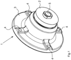
- the bearing arrangement has a bearing unit 1 and a bearing pin 2 which can be rotated in the bearing unit 1.
- the bearing unit 1 comprises a round bearing housing 3.
- the bearing housing 3 is provided with a total of four bores 4, which can be used to attach the bearing unit 1 either to a rotating element designed as a floor roller 7, not shown here, or to one assigned to the floor roller 7 support frame 8, not shown.
- the bearing pin 2 has an internal thread 5, which can be used to fasten the bearing pin 2 to the other component, i.e. either the support frame 8 or the floor roller 7.
- the soil roller 7 can be arranged on an agricultural machine via the support frame 8 and used for soil cultivation.
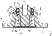
- the storage arrangement is in Fig.2 seen in sectional view.
- a rolling bearing designed as a double-row spherical roller bearing 6 is arranged in the bearing housing 3 of the bearing unit 1.
- the floor roller 7 and the support frame 8 can be rotatably connected via the bearing pin 2 mounted in the spherical roller bearing 6 of the storage unit 1, as in Fig.3 is shown.
- the bearing unit 1 is fastened to a blank 10 welded inside the floor roller 7 via releasable fastening means designed as screws 9 by means of the bores 4 in the bearing housing 3.
- only one of the two lateral ends of the floor roller 7 with the connection to the support frame 8 is shown here.
- a similar connection can be selected for the opposite end, not shown here.
- the bearing pin 2 is attached to the support frame 8 by means of a centering 11, which is also detachable.
- the centering 11 is screwed into the internal thread 5 with the aid of a washer 12, so that the bearing pin 2 is clamped with a flange 13, as Fig.4 shows.
- the flange 13 is in turn over one Another set of screws 9 'arranged on the support frame 8.
- the ground roller 7 can roll on the ground and rotate about a horizontal axis of rotation 15 that runs transversely to the direction of travel.
- the bearing unit 1 also has a sealing arrangement 16 in order to seal the circumferential gap between the bearing journal 2 and the bearing housing 3 in a liquid-tight and dust-tight manner.
- the spherical roller bearing 6 is thus protected from dirt thrown up during soil cultivation.
- the sealing arrangement 16 comprises a slide ring 17, a race 18 each made of high-alloy metal and a first and a second support ring 19a, 19b each made of elastomer.
- the sliding ring 17 is not rotatably fixed to the bearing housing 3 and surrounds the bearing journal 2.
- the race 18 encloses the bearing journal 2 in an at least approximately liquid-tight manner and is not rotatably arranged on the same.
- the slide ring 17 is braced via the support by means of the first support ring 19a on the bearing housing 3 with the race 18 via its support by means of the second support ring 19b on the bearing journal 2 on mutually facing running surfaces 20a, 20b.
- the lapped running surfaces 20a, 20b slide on one another and, together with the first and second support rings 19a, 19b, seal the circumferential gap between the bearing journal 2 and the bearing housing 3.
- the back of the bearing housing 3 is closed by a detachable bearing cap 21 provided with a circumferential sealing lip 22, so that the bearing housing 3 is designed to be at least approximately liquid-tight or oil-tight and dust-tight.
- the bearing housing 3 of the bearing unit 1 can be provided with oil bath lubrication and the spherical roller bearing 6 is reliably protected from the ingress of splash water.
- an angular offset ⁇ occurs between the longitudinal axis of the bearing housing 3, which is formed perpendicular to the obliquely welded blank 10, and the longitudinal axis of the bearing journal 2, which in this case corresponds to the axis of rotation 15.
- the spherical roller bearing 6 is set up to compensate for this angular offset ⁇ , in that the bearing inner ring tilts relative to the bearing outer ring and thus brings the axes together again.
- the sealing arrangement 16 Since the sealing arrangement 16 is arranged partly on the bearing housing 3 and partly on the bearing journal 2, in order to maintain the protection of the bearing arrangement even when there is an angular offset ⁇ , it is necessary that the sealing arrangement 16 follows the angular offset ⁇ :
- the elasticity of the first and second support ring 19a, 19b ensures that the slide ring 17 with the race 18 is held in contact with the running surfaces 20a, 20b while the transition between the slide ring 17 and the bearing housing 3 as well as between the race 18 and the bearing journal 2 are equally sealed.
- the first and second support rings 19a, 19b are compressed during assembly, so that when the angular offset ⁇ occurs, they can expand on the one hand and, on the other hand, are further compressed in order to follow the same.
- FIG.6 A further exemplary embodiment of a bearing arrangement according to the invention is shown in Fig.6 to see.
- the structure essentially corresponds to the structure of the first exemplary embodiment in the Fig.1-5 .
- the difference lies in the reverse formation of the bearing arrangement.
- the bearing pin 2 is attached to the floor roller 7 by means of a cohesive joining process.
- the bearing pin 2 is welded to the blank 10. It is also conceivable that the bearing pin 2 is glued to the blank 10 using adhesive.
- the bearing housing 3 is arranged on the support frame 8 by means of screws 9 passed through the holes 4. In this respect, the arrangement of the bearing journal 2 and the bearing housing 3 is compared to that in the Fig.1-5 shown embodiment swapped.
Landscapes
- Engineering & Computer Science (AREA)
- General Engineering & Computer Science (AREA)
- Mechanical Engineering (AREA)
- Life Sciences & Earth Sciences (AREA)
- Soil Sciences (AREA)
- Environmental Sciences (AREA)
- Rolling Contact Bearings (AREA)
Applications Claiming Priority (1)
| Application Number | Priority Date | Filing Date | Title |
|---|---|---|---|
| DE102018122932.1A DE102018122932A1 (de) | 2018-09-19 | 2018-09-19 | Landwirtschaftliche Maschine |
Publications (2)
| Publication Number | Publication Date |
|---|---|
| EP3626039A1 EP3626039A1 (de) | 2020-03-25 |
| EP3626039B1 true EP3626039B1 (de) | 2023-10-11 |
Family
ID=68136322
Family Applications (1)
| Application Number | Title | Priority Date | Filing Date |
|---|---|---|---|
| EP19401033.6A Active EP3626039B1 (de) | 2018-09-19 | 2019-09-04 | Lageranordnung und landwirtschaftliche maschine mit dieser lageranordnung |
Country Status (4)
| Country | Link |
|---|---|
| EP (1) | EP3626039B1 (pl) |
| DE (1) | DE102018122932A1 (pl) |
| HU (1) | HUE064311T2 (pl) |
| PL (1) | PL3626039T3 (pl) |
Families Citing this family (1)
| Publication number | Priority date | Publication date | Assignee | Title |
|---|---|---|---|---|
| ES3044860T3 (en) * | 2020-05-29 | 2025-11-27 | Maschio Gaspardo Spa | Rotatable support with flanged journal |
Family Cites Families (5)
| Publication number | Priority date | Publication date | Assignee | Title |
|---|---|---|---|---|
| US4249782A (en) * | 1979-09-11 | 1981-02-10 | Deere & Company | Self-aligning bearing and seal |
| DE20010216U1 (de) * | 2000-06-09 | 2001-10-18 | Hugo Vogelsang Maschinenbau GmbH, 49632 Essen | Axiale Dichtung |
| DE102013102871A1 (de) * | 2013-03-21 | 2014-10-09 | Amazonen-Werke H. Dreyer Gmbh & Co. Kg | Landwirtschaftliche Maschine |
| SE541106C2 (sv) * | 2012-08-22 | 2019-04-09 | Vaederstad Holding Ab | Fjädringsenhet för lantbruksredskap, lantbruksredskap samt användning och förfarande för montering av lagerenhet |
| CN206830673U (zh) * | 2017-06-20 | 2018-01-02 | 湖南一田农业机械有限公司 | 一种旋耕机刀轴密封轴承座 |
-
2018
- 2018-09-19 DE DE102018122932.1A patent/DE102018122932A1/de not_active Withdrawn
-
2019
- 2019-09-04 HU HUE19401033A patent/HUE064311T2/hu unknown
- 2019-09-04 PL PL19401033.6T patent/PL3626039T3/pl unknown
- 2019-09-04 EP EP19401033.6A patent/EP3626039B1/de active Active
Also Published As
| Publication number | Publication date |
|---|---|
| HUE064311T2 (hu) | 2024-03-28 |
| DE102018122932A1 (de) | 2020-03-19 |
| PL3626039T3 (pl) | 2024-02-05 |
| EP3626039A1 (de) | 2020-03-25 |
Similar Documents
| Publication | Publication Date | Title |
|---|---|---|
| DE102010061932B3 (de) | Wälzlager mit austauschbarer Dichtung | |
| EP1585905B1 (de) | Dichtungsbaugruppe für eine lagerbüchse | |
| DE69911385T2 (de) | Schienenfahrzeuglageranordnung mit verbessertem reibkorrosionsverhalten | |
| EP2729712B1 (de) | Pendelrollenlager mit dichtungsanordnung sowie flossenstabilisator mit dem pendelrollenlager | |
| DE102013226555B4 (de) | Wälzlager mit Dichtungseinheit | |
| DE102019117942B4 (de) | Wellgetriebe und Lagerelement für ein Wellgetriebe | |
| DE102017107005B3 (de) | Abgedichtetes Wälzlager | |
| WO2019114853A1 (de) | Dichtungsanordnung eines radlagers | |
| DE102021104268B3 (de) | Lageranordnung und Roboterarm | |
| DE2356266A1 (de) | Trommellagerung | |
| EP3689120B1 (de) | Lagereinheit und landwirtschaftliche maschine mit einer solchen lagereinheit | |
| DE102022212021A1 (de) | Lagereinheit mit einer Dichtvorrichtung | |
| DE4231863A1 (de) | Foerderbandrolle | |
| DE69005183T2 (de) | Lager mit Dichtung für Antriebswellen in Kraftfahrzeugen. | |
| EP3626039A1 (de) | Landwirtschaftliche maschine | |
| DE102019200398A1 (de) | Selbst-ausrichtendes Rollenlager | |
| EP1138968A1 (de) | Labyrinthdichtung für eine Gelenkkreuzwelle | |
| WO2005116312A1 (de) | Oberwalze für spinnereimaschinen-streckweke | |
| DE102005060499B4 (de) | Wälzlageranordnung | |
| DE102012006466B4 (de) | Welle zur Übertragung eines Drehmoments | |
| DE102021100959A1 (de) | Gehäuseelement mit axial bewegbarer Lagereinheit | |
| DE102021212337A1 (de) | Lagereinheit, die aus kohlenstoffarmem Stahl hergestellt ist | |
| DE102016212376B4 (de) | Anordnung mit einer ortsfesten Struktur | |
| DE102023113577B4 (de) | Lagerung | |
| DE10000659B4 (de) | Dichtung für das Lager einer Breitstreckwalze und deren Montageverfahren |
Legal Events
| Date | Code | Title | Description |
|---|---|---|---|
| PUAI | Public reference made under article 153(3) epc to a published international application that has entered the european phase |
Free format text: ORIGINAL CODE: 0009012 |
|
| STAA | Information on the status of an ep patent application or granted ep patent |
Free format text: STATUS: THE APPLICATION HAS BEEN PUBLISHED |
|
| AK | Designated contracting states |
Kind code of ref document: A1 Designated state(s): AL AT BE BG CH CY CZ DE DK EE ES FI FR GB GR HR HU IE IS IT LI LT LU LV MC MK MT NL NO PL PT RO RS SE SI SK SM TR |
|
| AX | Request for extension of the european patent |
Extension state: BA ME |
|
| STAA | Information on the status of an ep patent application or granted ep patent |
Free format text: STATUS: REQUEST FOR EXAMINATION WAS MADE |
|
| 17P | Request for examination filed |
Effective date: 20200916 |
|
| RBV | Designated contracting states (corrected) |
Designated state(s): AL AT BE BG CH CY CZ DE DK EE ES FI FR GB GR HR HU IE IS IT LI LT LU LV MC MK MT NL NO PL PT RO RS SE SI SK SM TR |
|
| RAP3 | Party data changed (applicant data changed or rights of an application transferred) |
Owner name: AMAZONEN-WERK H. DREYER SE & CO. KG |
|
| RAP3 | Party data changed (applicant data changed or rights of an application transferred) |
Owner name: AMAZONEN-WERKE H. DREYER SE & CO. KG |
|
| STAA | Information on the status of an ep patent application or granted ep patent |
Free format text: STATUS: EXAMINATION IS IN PROGRESS |
|
| 17Q | First examination report despatched |
Effective date: 20221018 |
|
| GRAP | Despatch of communication of intention to grant a patent |
Free format text: ORIGINAL CODE: EPIDOSNIGR1 |
|
| STAA | Information on the status of an ep patent application or granted ep patent |
Free format text: STATUS: GRANT OF PATENT IS INTENDED |
|
| P01 | Opt-out of the competence of the unified patent court (upc) registered |
Effective date: 20230523 |
|
| INTG | Intention to grant announced |
Effective date: 20230623 |
|
| GRAS | Grant fee paid |
Free format text: ORIGINAL CODE: EPIDOSNIGR3 |
|
| GRAA | (expected) grant |
Free format text: ORIGINAL CODE: 0009210 |
|
| STAA | Information on the status of an ep patent application or granted ep patent |
Free format text: STATUS: THE PATENT HAS BEEN GRANTED |
|
| AK | Designated contracting states |
Kind code of ref document: B1 Designated state(s): AL AT BE BG CH CY CZ DE DK EE ES FI FR GB GR HR HU IE IS IT LI LT LU LV MC MK MT NL NO PL PT RO RS SE SI SK SM TR |
|
| REG | Reference to a national code |
Ref country code: GB Ref legal event code: FG4D Free format text: NOT ENGLISH |
|
| REG | Reference to a national code |
Ref country code: CH Ref legal event code: EP |
|
| REG | Reference to a national code |
Ref country code: DE Ref legal event code: R096 Ref document number: 502019009623 Country of ref document: DE |
|
| REG | Reference to a national code |
Ref country code: IE Ref legal event code: FG4D Free format text: LANGUAGE OF EP DOCUMENT: GERMAN |
|
| REG | Reference to a national code |
Ref country code: SE Ref legal event code: TRGR |
|
| REG | Reference to a national code |
Ref country code: SK Ref legal event code: T3 Ref document number: E 42731 Country of ref document: SK |
|
| REG | Reference to a national code |
Ref country code: LT Ref legal event code: MG9D |
|
| REG | Reference to a national code |
Ref country code: NL Ref legal event code: MP Effective date: 20231011 |
|
| REG | Reference to a national code |
Ref country code: HU Ref legal event code: AG4A Ref document number: E064311 Country of ref document: HU |
|
| PG25 | Lapsed in a contracting state [announced via postgrant information from national office to epo] |
Ref country code: NL Free format text: LAPSE BECAUSE OF FAILURE TO SUBMIT A TRANSLATION OF THE DESCRIPTION OR TO PAY THE FEE WITHIN THE PRESCRIBED TIME-LIMIT Effective date: 20231011 |
|
| PG25 | Lapsed in a contracting state [announced via postgrant information from national office to epo] |
Ref country code: GR Free format text: LAPSE BECAUSE OF FAILURE TO SUBMIT A TRANSLATION OF THE DESCRIPTION OR TO PAY THE FEE WITHIN THE PRESCRIBED TIME-LIMIT Effective date: 20240112 |
|
| PG25 | Lapsed in a contracting state [announced via postgrant information from national office to epo] |
Ref country code: IS Free format text: LAPSE BECAUSE OF FAILURE TO SUBMIT A TRANSLATION OF THE DESCRIPTION OR TO PAY THE FEE WITHIN THE PRESCRIBED TIME-LIMIT Effective date: 20240211 |
|
| PG25 | Lapsed in a contracting state [announced via postgrant information from national office to epo] |
Ref country code: LT Free format text: LAPSE BECAUSE OF FAILURE TO SUBMIT A TRANSLATION OF THE DESCRIPTION OR TO PAY THE FEE WITHIN THE PRESCRIBED TIME-LIMIT Effective date: 20231011 |
|
| PG25 | Lapsed in a contracting state [announced via postgrant information from national office to epo] |
Ref country code: ES Free format text: LAPSE BECAUSE OF FAILURE TO SUBMIT A TRANSLATION OF THE DESCRIPTION OR TO PAY THE FEE WITHIN THE PRESCRIBED TIME-LIMIT Effective date: 20231011 |
|
| PG25 | Lapsed in a contracting state [announced via postgrant information from national office to epo] |
Ref country code: LT Free format text: LAPSE BECAUSE OF FAILURE TO SUBMIT A TRANSLATION OF THE DESCRIPTION OR TO PAY THE FEE WITHIN THE PRESCRIBED TIME-LIMIT Effective date: 20231011 Ref country code: IS Free format text: LAPSE BECAUSE OF FAILURE TO SUBMIT A TRANSLATION OF THE DESCRIPTION OR TO PAY THE FEE WITHIN THE PRESCRIBED TIME-LIMIT Effective date: 20240211 Ref country code: GR Free format text: LAPSE BECAUSE OF FAILURE TO SUBMIT A TRANSLATION OF THE DESCRIPTION OR TO PAY THE FEE WITHIN THE PRESCRIBED TIME-LIMIT Effective date: 20240112 Ref country code: ES Free format text: LAPSE BECAUSE OF FAILURE TO SUBMIT A TRANSLATION OF THE DESCRIPTION OR TO PAY THE FEE WITHIN THE PRESCRIBED TIME-LIMIT Effective date: 20231011 Ref country code: BG Free format text: LAPSE BECAUSE OF FAILURE TO SUBMIT A TRANSLATION OF THE DESCRIPTION OR TO PAY THE FEE WITHIN THE PRESCRIBED TIME-LIMIT Effective date: 20240111 Ref country code: PT Free format text: LAPSE BECAUSE OF FAILURE TO SUBMIT A TRANSLATION OF THE DESCRIPTION OR TO PAY THE FEE WITHIN THE PRESCRIBED TIME-LIMIT Effective date: 20240212 |
|
| PG25 | Lapsed in a contracting state [announced via postgrant information from national office to epo] |
Ref country code: RS Free format text: LAPSE BECAUSE OF FAILURE TO SUBMIT A TRANSLATION OF THE DESCRIPTION OR TO PAY THE FEE WITHIN THE PRESCRIBED TIME-LIMIT Effective date: 20231011 Ref country code: NO Free format text: LAPSE BECAUSE OF FAILURE TO SUBMIT A TRANSLATION OF THE DESCRIPTION OR TO PAY THE FEE WITHIN THE PRESCRIBED TIME-LIMIT Effective date: 20240111 Ref country code: LV Free format text: LAPSE BECAUSE OF FAILURE TO SUBMIT A TRANSLATION OF THE DESCRIPTION OR TO PAY THE FEE WITHIN THE PRESCRIBED TIME-LIMIT Effective date: 20231011 Ref country code: HR Free format text: LAPSE BECAUSE OF FAILURE TO SUBMIT A TRANSLATION OF THE DESCRIPTION OR TO PAY THE FEE WITHIN THE PRESCRIBED TIME-LIMIT Effective date: 20231011 |
|
| PG25 | Lapsed in a contracting state [announced via postgrant information from national office to epo] |
Ref country code: DK Free format text: LAPSE BECAUSE OF FAILURE TO SUBMIT A TRANSLATION OF THE DESCRIPTION OR TO PAY THE FEE WITHIN THE PRESCRIBED TIME-LIMIT Effective date: 20231011 |
|
| REG | Reference to a national code |
Ref country code: DE Ref legal event code: R097 Ref document number: 502019009623 Country of ref document: DE |
|
| PG25 | Lapsed in a contracting state [announced via postgrant information from national office to epo] |
Ref country code: SM Free format text: LAPSE BECAUSE OF FAILURE TO SUBMIT A TRANSLATION OF THE DESCRIPTION OR TO PAY THE FEE WITHIN THE PRESCRIBED TIME-LIMIT Effective date: 20231011 Ref country code: EE Free format text: LAPSE BECAUSE OF FAILURE TO SUBMIT A TRANSLATION OF THE DESCRIPTION OR TO PAY THE FEE WITHIN THE PRESCRIBED TIME-LIMIT Effective date: 20231011 Ref country code: DK Free format text: LAPSE BECAUSE OF FAILURE TO SUBMIT A TRANSLATION OF THE DESCRIPTION OR TO PAY THE FEE WITHIN THE PRESCRIBED TIME-LIMIT Effective date: 20231011 |
|
| PLBE | No opposition filed within time limit |
Free format text: ORIGINAL CODE: 0009261 |
|
| STAA | Information on the status of an ep patent application or granted ep patent |
Free format text: STATUS: NO OPPOSITION FILED WITHIN TIME LIMIT |
|
| 26N | No opposition filed |
Effective date: 20240712 |
|
| PG25 | Lapsed in a contracting state [announced via postgrant information from national office to epo] |
Ref country code: SI Free format text: LAPSE BECAUSE OF FAILURE TO SUBMIT A TRANSLATION OF THE DESCRIPTION OR TO PAY THE FEE WITHIN THE PRESCRIBED TIME-LIMIT Effective date: 20231011 |
|
| PG25 | Lapsed in a contracting state [announced via postgrant information from national office to epo] |
Ref country code: SI Free format text: LAPSE BECAUSE OF FAILURE TO SUBMIT A TRANSLATION OF THE DESCRIPTION OR TO PAY THE FEE WITHIN THE PRESCRIBED TIME-LIMIT Effective date: 20231011 |
|
| PG25 | Lapsed in a contracting state [announced via postgrant information from national office to epo] |
Ref country code: MC Free format text: LAPSE BECAUSE OF FAILURE TO SUBMIT A TRANSLATION OF THE DESCRIPTION OR TO PAY THE FEE WITHIN THE PRESCRIBED TIME-LIMIT Effective date: 20231011 |
|
| REG | Reference to a national code |
Ref country code: CH Ref legal event code: PL |
|
| PG25 | Lapsed in a contracting state [announced via postgrant information from national office to epo] |
Ref country code: LU Free format text: LAPSE BECAUSE OF NON-PAYMENT OF DUE FEES Effective date: 20240904 |
|
| PGFP | Annual fee paid to national office [announced via postgrant information from national office to epo] |
Ref country code: PL Payment date: 20250612 Year of fee payment: 7 |
|
| REG | Reference to a national code |
Ref country code: BE Ref legal event code: MM Effective date: 20240930 |
|
| PG25 | Lapsed in a contracting state [announced via postgrant information from national office to epo] |
Ref country code: BE Free format text: LAPSE BECAUSE OF NON-PAYMENT OF DUE FEES Effective date: 20240930 |
|
| PG25 | Lapsed in a contracting state [announced via postgrant information from national office to epo] |
Ref country code: CH Free format text: LAPSE BECAUSE OF NON-PAYMENT OF DUE FEES Effective date: 20240930 |
|
| PG25 | Lapsed in a contracting state [announced via postgrant information from national office to epo] |
Ref country code: IE Free format text: LAPSE BECAUSE OF NON-PAYMENT OF DUE FEES Effective date: 20240904 |
|
| PG25 | Lapsed in a contracting state [announced via postgrant information from national office to epo] |
Ref country code: FI Free format text: LAPSE BECAUSE OF FAILURE TO SUBMIT A TRANSLATION OF THE DESCRIPTION OR TO PAY THE FEE WITHIN THE PRESCRIBED TIME-LIMIT Effective date: 20231011 |
|
| PGFP | Annual fee paid to national office [announced via postgrant information from national office to epo] |
Ref country code: DE Payment date: 20250702 Year of fee payment: 7 |
|
| PGFP | Annual fee paid to national office [announced via postgrant information from national office to epo] |
Ref country code: IT Payment date: 20250825 Year of fee payment: 7 |
|
| PGFP | Annual fee paid to national office [announced via postgrant information from national office to epo] |
Ref country code: HU Payment date: 20250813 Year of fee payment: 7 Ref country code: GB Payment date: 20250703 Year of fee payment: 7 |
|
| PGFP | Annual fee paid to national office [announced via postgrant information from national office to epo] |
Ref country code: FR Payment date: 20250703 Year of fee payment: 7 Ref country code: AT Payment date: 20250827 Year of fee payment: 7 |
|
| PGFP | Annual fee paid to national office [announced via postgrant information from national office to epo] |
Ref country code: SE Payment date: 20250702 Year of fee payment: 7 |
|
| PGFP | Annual fee paid to national office [announced via postgrant information from national office to epo] |
Ref country code: CZ Payment date: 20250821 Year of fee payment: 7 |
|
| PGFP | Annual fee paid to national office [announced via postgrant information from national office to epo] |
Ref country code: RO Payment date: 20250729 Year of fee payment: 7 |
|
| PGFP | Annual fee paid to national office [announced via postgrant information from national office to epo] |
Ref country code: SK Payment date: 20250723 Year of fee payment: 7 |
|
| PG25 | Lapsed in a contracting state [announced via postgrant information from national office to epo] |
Ref country code: CY Free format text: LAPSE BECAUSE OF FAILURE TO SUBMIT A TRANSLATION OF THE DESCRIPTION OR TO PAY THE FEE WITHIN THE PRESCRIBED TIME-LIMIT; INVALID AB INITIO Effective date: 20190904 |