EP3625807B1 - Hot deformed magnet, and a method for preparing said hot deformed magnet - Google Patents
Hot deformed magnet, and a method for preparing said hot deformed magnet Download PDFInfo
- Publication number
- EP3625807B1 EP3625807B1 EP17910333.8A EP17910333A EP3625807B1 EP 3625807 B1 EP3625807 B1 EP 3625807B1 EP 17910333 A EP17910333 A EP 17910333A EP 3625807 B1 EP3625807 B1 EP 3625807B1
- Authority
- EP
- European Patent Office
- Prior art keywords
- hot
- hot deformed
- deformed magnet
- magnet
- green body
- Prior art date
- Legal status (The legal status is an assumption and is not a legal conclusion. Google has not performed a legal analysis and makes no representation as to the accuracy of the status listed.)
- Active
Links
Images

Classifications
-
- H—ELECTRICITY
- H01—ELECTRIC ELEMENTS
- H01F—MAGNETS; INDUCTANCES; TRANSFORMERS; SELECTION OF MATERIALS FOR THEIR MAGNETIC PROPERTIES
- H01F1/00—Magnets or magnetic bodies characterised by the magnetic materials therefor; Selection of materials for their magnetic properties
- H01F1/01—Magnets or magnetic bodies characterised by the magnetic materials therefor; Selection of materials for their magnetic properties of inorganic materials
- H01F1/03—Magnets or magnetic bodies characterised by the magnetic materials therefor; Selection of materials for their magnetic properties of inorganic materials characterised by their coercivity
- H01F1/032—Magnets or magnetic bodies characterised by the magnetic materials therefor; Selection of materials for their magnetic properties of inorganic materials characterised by their coercivity of hard-magnetic materials
- H01F1/04—Magnets or magnetic bodies characterised by the magnetic materials therefor; Selection of materials for their magnetic properties of inorganic materials characterised by their coercivity of hard-magnetic materials metals or alloys
- H01F1/047—Alloys characterised by their composition
- H01F1/053—Alloys characterised by their composition containing rare earth metals
- H01F1/055—Alloys characterised by their composition containing rare earth metals and magnetic transition metals, e.g. SmCo5
- H01F1/057—Alloys characterised by their composition containing rare earth metals and magnetic transition metals, e.g. SmCo5 and IIIa elements, e.g. Nd2Fe14B
- H01F1/0571—Alloys characterised by their composition containing rare earth metals and magnetic transition metals, e.g. SmCo5 and IIIa elements, e.g. Nd2Fe14B in the form of particles, e.g. rapid quenched powders or ribbon flakes
- H01F1/0575—Alloys characterised by their composition containing rare earth metals and magnetic transition metals, e.g. SmCo5 and IIIa elements, e.g. Nd2Fe14B in the form of particles, e.g. rapid quenched powders or ribbon flakes pressed, sintered or bonded together
- H01F1/0576—Alloys characterised by their composition containing rare earth metals and magnetic transition metals, e.g. SmCo5 and IIIa elements, e.g. Nd2Fe14B in the form of particles, e.g. rapid quenched powders or ribbon flakes pressed, sintered or bonded together pressed, e.g. hot working
Definitions
- the present invention relates to a hot deformed magnet, as well as a method for preparing said hot deformed magnet.
- rare earth/iron/boron-based permanent magnet exhibits high remanence and coercivty, provides a high magnetic flux within a specific temperature range (for example -40 ⁇ 180 °C for EV/HEV traction motor), and makes the electric motor have superior performances, for example high power density, high torque density and high efficiency.
- the coercivity is the magnitude of magnetic field at which the magnetization of a permanent magnet is reduced to zero. It stands for the ability of the permanent magnet to generate a magnetic flux against the demagnetization field and also the ability of the permanent magnet to generate a magnetic flux against the high working temperature.
- the remanence represents the magnitude of the maximum magnetic flux which can be generated by the permanent magnet. It represents the ability of the permanent magnet to provide a magnetic moment. Normally a high remanence is favorable to render a permanent magnet thinner and lighter in case of a fixed magnetic moment, and consequently reduce the size and volume of an electric motor, which is desirable for many applications.
- Coarsen grain regions are mainly generated at the original place of the magnetic powder particulate surfaces during the hot deformation.
- the RE 2 F 14 B grains are almost equiaxed instead of platelet, and often have a dimension of greater than 400 nm. These equiaxed large RE 2 F 14 B grains exhibit a low magnetic orientation, a low ability against the demagnetization field, and consequently deteriorated magnetic properties. Due to the presence of coarsen grain regions, a remanence as high as 1.45 T or above normally can not be achieved for the conventional hot deformed magnets.
- US 5 395 462 A and US 5 211 766 A show prior art examples of hot pressed NdFeB-based magnets.
- CN 106 448 986 A shows a cold pressed CeFeB-based magnet and FR 2 779 267 A1 a forged NdFeB-based magnet.
- the object of the present invention is to provide a hot deformed magnet which has enhanced magnetic properties, especially enhanced remanence and coercivity, and almost has no coarse equiaxed grains with a diameter greater than 400 nm and consequently no coarse equiaxed grain regions in the microstructure.
- Said object can be achieved by a hot deformed magnet having an alloy composition of the formula (1) RE x Fe (100-x-y1-y2-z1-z2) T y1 M y2 Cu z1 B z2 (1), wherein
- Said object can be achieved by a method for preparing the hot deformed magnet according to the present invention, said method including the following steps:
- the present invention relates to a hot deformed magnet having an alloy composition of the formula (1) RE x Fe (100-x-y1-y2-z1-z2) T y1 M y2 Cu z1 B z2 (1), wherein
- the hot deformed magnet can contain a predominant magnetic phase and one or more grain boundary phases.
- the predominant magnetic phase is the RE 2 Fe 14 B phase having a tetragonal crystal structure.
- the formula RE 2 Fe 14 B as used herein includes all the compositions having the RE 2 Fe 14 B tetragonal crystal structure, which may or may not include any other elements as stated above, as long as these other elements do not destroy the RE 2 Fe 14 B tetragonal crystal structure.
- the specific compositions and crystal structures of said one or more grain boundary phases are quite complicated. At least one of the grain boundary phases are believed to have a lower melting temperature and a greater proportion of rare earth element(s) than those of the predominant magnetic phase, and therefore, can also be called as RE-rich phase. Another grain boundary phase is believed to be present in form of nano-sized Nb-rich and/or Ta-rich precipitates.
- the hot deformed magnet can exhibit anisotropy with a RE 2 Fe 14 B grain morphology in form of platelet.
- the hot deformed magnet can exhibit anisotropy with the crystallographic c-axes of the RE 2 Fe 14 B grains aligned or orientated substantially parallel to one another.
- the crystallographic c-axes of the RE 2 Fe 14 B grains in form of platelet are perpendicular to the major surfaces of the platelets and parallel to their smallest dimension.
- the preferred magnetic alignment direction of the RE 2 Fe 14 B grains is along their crystallographic c-axes.
- the thickness of the platelet can be up to 200 nm, preferably 25 - 120 nm, more preferably 25 - 100 nm. In the context of the present invention, the thickness of the platelet shall be understood as its smallest dimension.
- the length of the platelet can be up to 1 ⁇ m, preferably 100 - 600 nm, more preferably 100 - 300 nm. In the context of the present invention, the length of the platelet shall be understood as its largest dimension.
- the hot deformed magnet almost has no coarse equiaxed grains with a diameter greater than 400 nm and consequently no coarse equiaxed grain regions in the microstructure.
- the present invention relates to a method for preparing the hot deformed magnet according to the present invention, including the following steps:
- step 1) magnetic powders can be prepared by melt quenching from an ingot having the alloy composition of the formula (1).
- the ingot can be melted at a temperature of above 1000 °C, preferably 1000 ⁇ 1100 °C, preferably under a protect atmosphere, such as Argon, and then cast or injected onto a rotating wheel, such as a copper wheel, with a circumferential velocity of 10 ⁇ 40 m/s, so as to obtain melt-spun ribbons or magnetic powders.
- the cooling rate can be set according to the circumferential velocity of the rotating wheel and the amount of the molten metal cast or injected.
- melt-spun ribbons can be directly obtained by melt quenching from the ingot, and preferably have a thickness of less than 50 ⁇ m. Then the melt-spun ribbons can be optionally crushed into magnetic powders preferably having a length of less than 200 ⁇ m.
- the magnetic powders or the melt-spun ribbons can be crystalline or even amorphous, or have crystallitic grains with a grain size of less than 50 nm, in each case according to the cooling rate.
- step 2) the magnetic powders prepared from step 1) can be pressed to obtain a green body.
- the magnetic powders prepared from step 1) can be cold pressed at room temperature, wherein the pressure and the duration of the cold pressing are not particularly limited and can be selected in such a way to reach up to 70% or even more of the saturated density, for example 50 ⁇ 400 MPa and 1 ⁇ 5 seconds; and then hot pressed to obtain the green body, wherein the temperature of the hot pressing is not particularly limited, for example 550 ⁇ 850 °C, preferably 600 ⁇ 700 °C, and can be selected in such a way not to liquefy the predominant magnetic phase, but liquefy the grain boundary phase sufficiently, otherwise the densification might be insufficient and even cracks might be initiated and propagated in the green body; the pressure of the hot pressing is not particularly limited, for example 20 ⁇ 200 MPa, preferably 20 ⁇ 100 MPa, and can be selected in such a way to reach the full densification; the duration of the hot pressing is not particularly limited, for example 10 ⁇ 240 seconds, and can be selected
- step 3 the green body prepared from step 2) can be hot deformed to obtain the hot deformed magnet.
- the green body prepared from step 2) can be hot deformed, for example by extrusion, or die up-setting, so as to reshape the green body into the predetermined shape and geometry, such as cylinder, rectangular block or segment, and simultaneously align the crystallographic c-axes of the RE 2 Fe 14 B grains to the predetermined direction, and finally obtain the hot deformed magnet, wherein the temperature of the hot deformation is not particularly limited, for example 750 ⁇ 850 °C, preferably 780 ⁇ 820 °C, and can be selected in such a way to subject the green body to a plastic deformation, but not initiate and propagate cracks in the green body; the pressure of the hot deformation is not particularly limited, for example 20 ⁇ 250 MPa, preferably 20 ⁇ 200 MPa; and the atmosphere of the hot deformation is not particularly limited, for example an inert gas protected atmosphere, a reduction atmosphere, vacuum or a low oxidation atmosphere.
- the temperature of the hot deformation is not particularly limited, for example 750 ⁇ 850 °
- the anisotropy of the RE 2 Fe 14 B grains can be achieved based on such a mechanism that the RE 2 Fe 14 B grains can rotate during the hot deformation under pressure with the help of the grain boundary phase liquefied at the hot deformation temperature, so that the crystallographic c-axes of the RE 2 Fe 14 B grains can be aligned or orientated substantially parallel to one another.
- the crystallographic c-axes of the RE 2 Fe 14 B grains in form of platelet are perpendicular to the major surfaces of the platelets and parallel to their smallest dimension.
- the preferred magnetic alignment direction of the RE 2 Fe 14 B grains is along their crystallographic c-axes.
- the hot deformed magnet can be further processed by thermal annealing, grain boundary diffusion or other post treatment under cold or warm conditions.
- Raw materials according to the alloy compositions as listed in Table 1 were melted under Argon at a temperature of above 1000 °C until homogeneous, and cast into ingots.
- the ingots were melted again under Argon at a temperature of above 1000 °C, and then injected onto a copper wheel with a circumferential velocity of 20 m/s to obtain melt-spun ribbons. Then the melt-spun ribbons were crushed into magnetic powders having a length of less than 200 ⁇ m.
- the magnetic powders prepared from step 1) were cold pressed at room temperature for about 5 seconds to reach at least 70% of the saturated density, and then hot pressed under vacuum at about 700 °C and about 100 MPa for about 120 seconds to obtain green bodies.
- the green bodies prepared from step 2) were hot deformed by extrusion under vacuum at about 800 °C and about 180 MPa to obtain hot deformed magnets.
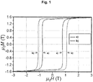
- Figure 1 shows the magnetization curves of the hot deformed magnets without Nb (a) (Example 1) and with about 0.2% of Nb (b) (Example 2).
- the magnetic properties of the hot deformed magnets prepared according to Examples 1 ⁇ 5 are listed in Table 2.
- the hot deformed magnets prepared according to Examples 1 ⁇ 5 exhibit very high remanences, for example 1.54 T as the highest and a corresponding anisotropy of 0.96, wherein the anisotropy is represented as the ratio of the remanence to the saturation magnetic flux density of 1.6 T.
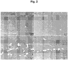
- Figure 2 shows the back-scattered SEM images of the hot deformed magnets without Nb (a) and (c) (Example 1) and with about 0.2% of Nb (b) and (d) (Example 2).
- the platelet-shaped morphology of the RE 2 Fe 14 B grains has been optimized by adding Nb.
- both the grain size and the aspect ratio of the RE 2 Fe 14 B grains have been reduced, which is beneficial to enhance the coercivity and the thermal stability of the coericivty of the hot deformed magnets.
- the aspect ratio of the platelet shall be understood as the ratio of the length to the thickness of the platelet.
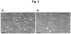
- Figure 3 shows the BSE-SEM images of the hot deformed magnets without Nb (a) (Example 1) and with about 0.2% of Nb (b) (Example 2). It is apparent from Figure 3 that both the grain size and the aspect ratio of the RE 2 Fe 14 B grains have been reduced.
- Figure 4 shows the STEM-EDS mapping of Nd and Nb of the hot deformed magnets with about 0.2% of Nb (a) (Example 2) and with about 0.6% of Nb (b) (Example 4).
- Nb mainly forms nano-sized Nb-rich precipitates at the grain boundary and slightly segregates inside the RE 2 Fe 14 B grains.
- Hot deformed magnet includes, but are not limited to, electric motor for automotives, power tools, home appliances, drive & control, and others.
Landscapes
- Chemical & Material Sciences (AREA)
- Crystallography & Structural Chemistry (AREA)
- Inorganic Chemistry (AREA)
- Engineering & Computer Science (AREA)
- Power Engineering (AREA)
- Hard Magnetic Materials (AREA)
- Manufacturing Cores, Coils, And Magnets (AREA)
- Manufacture Of Metal Powder And Suspensions Thereof (AREA)
- Powder Metallurgy (AREA)
- Continuous Casting (AREA)
Description
- The present invention relates to a hot deformed magnet, as well as a method for preparing said hot deformed magnet.
- Generally, rare earth/iron/boron-based permanent magnet exhibits high remanence and coercivty, provides a high magnetic flux within a specific temperature range (for example -40 ∼ 180 °C for EV/HEV traction motor), and makes the electric motor have superior performances, for example high power density, high torque density and high efficiency.
- The coercivity is the magnitude of magnetic field at which the magnetization of a permanent magnet is reduced to zero. It stands for the ability of the permanent magnet to generate a magnetic flux against the demagnetization field and also the ability of the permanent magnet to generate a magnetic flux against the high working temperature.
- The remanence represents the magnitude of the maximum magnetic flux which can be generated by the permanent magnet. It represents the ability of the permanent magnet to provide a magnetic moment. Normally a high remanence is favorable to render a permanent magnet thinner and lighter in case of a fixed magnetic moment, and consequently reduce the size and volume of an electric motor, which is desirable for many applications.
- Coarsen grain regions are mainly generated at the original place of the magnetic powder particulate surfaces during the hot deformation. In the coarsen grain regions, the RE2F14B grains are almost equiaxed instead of platelet, and often have a dimension of greater than 400 nm. These equiaxed large RE2F14B grains exhibit a low magnetic orientation, a low ability against the demagnetization field, and consequently deteriorated magnetic properties. Due to the presence of coarsen grain regions, a remanence as high as 1.45 T or above normally can not be achieved for the conventional hot deformed magnets.
- Although great efforts on the design of the alloy composition and the preparation method for the rare earth/iron/boron-based magnetic powders and hot deformed magnets have been made in the prior art, the issue of coarse equiaxed grains or coarsen grain regions is still not overcome for the known magnetic powders and hot deformed magnets
-
US 5 395 462 A andUS 5 211 766 A show prior art examples of hot pressed NdFeB-based magnets.CN 106 448 986 A shows a cold pressed CeFeB-based magnet andFR 2 779 267 A1 - The object of the present invention is to provide a hot deformed magnet which has enhanced magnetic properties, especially enhanced remanence and coercivity, and almost has no coarse equiaxed grains with a diameter greater than 400 nm and consequently no coarse equiaxed grain regions in the microstructure.
- Said object, according to one aspect, can be achieved by a hot deformed magnet having an alloy composition of the formula (1)
RExFe(100-x-y1-y2-z1-z2)Ty1My2Cuz1Bz2 (1),
wherein - RE is one or more rare earth elements, such as La, Ce, Pr, Nd, Sm, Eu, Gd, Tb, Dy, Ho, Er, Yb, and Lu, preferably Pr, Nd, Tb, and Dy;
- T is one or more elements selected from the group consisting of Co, Al, Ga, Zr, Ti and Mo;
- M is Nb and/or Ta;
- Cu is copper;
- B is boron;
- the balance is Fe and inevitable impurities;
- x is 13.0 ∼ 15.0 at.%;
- y1 is 1.2 ∼ 10.0 at.%;
- y2 is 0.1 ∼ 0.8 at.%;
- z1 is 0 ∼ 0.5 at.%; and
- z2 is 4.5 ∼ 6.5 at.%.
- Said object, according to another aspect, can be achieved by a method for preparing the hot deformed magnet according to the present invention, said method including the following steps:
- 1) preparing magnetic powders by melt quenching from an ingot having an alloy composition of the formula (1)
RExFe(100-x-y1-y2-z1-z2)Ty1My2Cuz1Bz2 (1),
wherein- RE is one or more rare earth elements, such as La, Ce, Pr, Nd, Sm, Eu, Gd, Tb, Dy, Ho, Er, Yb, and Lu, preferably Pr, Nd, Tb, and Dy;
- T is one or more elements selected from the group consisting of Co, Al, Ga, Zr, Ti and Mo;
- M is Nb and/or Ta;
- Cu is copper;
- B is boron;
- the balance is Fe and inevitable impurities;
- x is 13.0 ∼ 15.0 at.%;
- y1 is 1.2 ∼ 10.0 at.%;
- y2 is 0.1 ∼ 0.8 at.%;
- z1 is 0 ∼ 0.5 at.%; and
- z2 is 4.5 ∼ 6.5 at.%;
- 2) pressing the magnetic powders prepared from step 1) to obtain a green body; and
- 3) hot deforming the green body prepared from step 2) to obtain the hot deformed magnet.
- Each aspect of the present invention will be illustrated in more detail in conjunction with the accompanying drawings, wherein :
- Figure 1
- shows the magnetization curves of the hot deformed magnets without Nb (a) (Example 1) and with about 0.2% of Nb (b) (Example 2);
- Figure 2
- shows the back-scattered SEM images of the hot deformed magnets without Nb (a) and (c) (Example 1) and with about 0.2% of Nb (b) and (d) (Example 2);
- Figure 3
- shows the BSE-SEM images of the hot deformed magnets without Nb (a) (Example 1) and with about 0.2% of Nb (b) (Example 2);
- Figure 4
- shows the STEM-EDS mapping of Nd and Nb of the hot deformed magnets with about 0.2% of Nb (a) (Example 2) and with about 0.6% of Nb (b) (Example 4).
- Unless otherwise defined, all technical and scientific terms used herein have the same meaning as commonly understood by one of ordinary skill in the art to which this invention belongs. In case of conflict, the present specification, including definitions, will control.
- When an amount, concentration, or other value or parameter is given as either a range, preferred range or a list of upper preferable values and lower preferable values, this is to be understood as specifically disclosing all ranges formed from any pair of any upper range limit or preferred value and any lower range limit or preferred value, regardless of whether ranges are separately disclosed. Where a range of numerical values is recited herein, unless otherwise stated, the range is intended to include the endpoints thereof, and all integers and fractions within the range.
- The present invention, according to one aspect, relates to a hot deformed magnet having an alloy composition of the formula (1)
RExFe(100-x-y1-y2-z1-z2)Ty1My2Cuz1Bz2 (1),
wherein - RE is one or more rare earth elements, such as La, Ce, Pr, Nd, Sm, Eu, Gd, Tb, Dy, Ho, Er, Yb, and Lu, preferably Pr, Nd, Tb, and Dy;
- T is one or more elements selected from the group consisting of Co, Al, Ga, Zr, Ti and Mo;
- M is Nb and/or Ta;
- Cu is copper;
- B is boron;
- the balance is Fe and inevitable impurities;
- x is 13.0 ∼ 15.0 at.%;
- y1 is 1.2 ∼ 10.0 at.%;
- y2 is 0.1 ∼ 0.8 at.%;
- z1 is 0 ∼ 0.5 at.%; and
- z2 is 4.5 ∼ 6.5 at.%.
- In accordance with an embodiment of the hot deformed magnet according to the present invention, the hot deformed magnet can contain a predominant magnetic phase and one or more grain boundary phases.
- In particular, the predominant magnetic phase is the RE2Fe14B phase having a tetragonal crystal structure. In the context of the present invention, the formula RE2Fe14B as used herein includes all the compositions having the RE2Fe14B tetragonal crystal structure, which may or may not include any other elements as stated above, as long as these other elements do not destroy the RE2Fe14B tetragonal crystal structure.
- On the other hand, the specific compositions and crystal structures of said one or more grain boundary phases are quite complicated. At least one of the grain boundary phases are believed to have a lower melting temperature and a greater proportion of rare earth element(s) than those of the predominant magnetic phase, and therefore, can also be called as RE-rich phase. Another grain boundary phase is believed to be present in form of nano-sized Nb-rich and/or Ta-rich precipitates.
- In accordance with another embodiment of the hot deformed magnet according to the present invention, the hot deformed magnet can exhibit anisotropy with a RE2Fe14B grain morphology in form of platelet. In particular, the hot deformed magnet can exhibit anisotropy with the crystallographic c-axes of the RE2Fe14B grains aligned or orientated substantially parallel to one another. The crystallographic c-axes of the RE2Fe14B grains in form of platelet are perpendicular to the major surfaces of the platelets and parallel to their smallest dimension. The preferred magnetic alignment direction of the RE2Fe14B grains is along their crystallographic c-axes.
- In accordance with another embodiment of the hot deformed magnet according to the present invention, the thickness of the platelet can be up to 200 nm, preferably 25 - 120 nm, more preferably 25 - 100 nm. In the context of the present invention, the thickness of the platelet shall be understood as its smallest dimension.
- In accordance with another embodiment of the hot deformed magnet according to the present invention, the length of the platelet can be up to 1 µm, preferably 100 - 600 nm, more preferably 100 - 300 nm. In the context of the present invention, the length of the platelet shall be understood as its largest dimension.
- In accordance with another embodiment of the hot deformed magnet according to the present invention, the hot deformed magnet almost has no coarse equiaxed grains with a diameter greater than 400 nm and consequently no coarse equiaxed grain regions in the microstructure.
- The present invention, according to another aspect, relates to a method for preparing the hot deformed magnet according to the present invention, including the following steps:
- 1) preparing magnetic powders by melt quenching from an ingot having an alloy composition of the formula (1)
RExFe(100-x-y1-y2-z1-z2)Ty1My2Cuz1Bz2 (1),
wherein- RE is one or more rare earth elements, such as La, Ce, Pr, Nd, Sm, Eu, Gd, Tb, Dy, Ho, Er, Yb, and Lu, preferably Pr, Nd, Tb, and Dy;
- T is one or more elements selected from the group consisting of Co, Al, Ga, Zr, Ti and Mo;
- M is Nb and/or Ta;
- Cu is copper;
- B is boron;
- the balance is Fe and inevitable impurities;
- x is 13.0 ∼ 15.0 at.%;
- y1 is 1.2 ∼ 10.0 at.%;
- y2 is 0.1 ∼ 0.8 at.%;
- z1 is 0 ∼ 0.5 at.%; and
- z2 is 4.5 ∼ 6.5 at.%;
- 2) pressing the magnetic powders prepared from step 1) to obtain a green body; and
- 3) hot deforming the green body prepared from step 2) to obtain the hot deformed magnet.
- In step 1), magnetic powders can be prepared by melt quenching from an ingot having the alloy composition of the formula (1).
- In accordance with an embodiment of the method according to the present invention, the ingot can be melted at a temperature of above 1000 °C, preferably 1000 ∼ 1100 °C, preferably under a protect atmosphere, such as Argon, and then cast or injected onto a rotating wheel, such as a copper wheel, with a circumferential velocity of 10 ∼ 40 m/s, so as to obtain melt-spun ribbons or magnetic powders. The cooling rate can be set according to the circumferential velocity of the rotating wheel and the amount of the molten metal cast or injected.
- In accordance with another embodiment of the method according to the present invention, melt-spun ribbons can be directly obtained by melt quenching from the ingot, and preferably have a thickness of less than 50 µm. Then the melt-spun ribbons can be optionally crushed into magnetic powders preferably having a length of less than 200 µm.
- In accordance with another embodiment of the method according to the present invention, the magnetic powders or the melt-spun ribbons can be crystalline or even amorphous, or have crystallitic grains with a grain size of less than 50 nm, in each case according to the cooling rate.
- In step 2), the magnetic powders prepared from step 1) can be pressed to obtain a green body.
- In accordance with another embodiment of the method according to the present invention, the magnetic powders prepared from step 1) can be cold pressed at room temperature, wherein the pressure and the duration of the cold pressing are not particularly limited and can be selected in such a way to reach up to 70% or even more of the saturated density, for example 50 ∼ 400 MPa and 1 ∼ 5 seconds; and then hot pressed to obtain the green body, wherein the temperature of the hot pressing is not particularly limited, for example 550 ∼ 850 °C, preferably 600 ∼ 700 °C, and can be selected in such a way not to liquefy the predominant magnetic phase, but liquefy the grain boundary phase sufficiently, otherwise the densification might be insufficient and even cracks might be initiated and propagated in the green body; the pressure of the hot pressing is not particularly limited, for example 20 ∼ 200 MPa, preferably 20 ∼ 100 MPa, and can be selected in such a way to reach the full densification; the duration of the hot pressing is not particularly limited, for example 10 ∼ 240 seconds, and can be selected in such a way to reach the full densification, but shall not be too long to cause abnormal growth of the RE4Fe14B grains and consequently deteriorate the microstructure of the green body; and the atmosphere of the hot pressing is not particularly limited, for example an inert gas protected atmosphere, an oxidation atmosphere, a reduction atmosphere, and vacuum, preferably vacuum.
- In step 3), the green body prepared from step 2) can be hot deformed to obtain the hot deformed magnet.
- In accordance with another embodiment of the method according to the present invention, the green body prepared from step 2) can be hot deformed, for example by extrusion, or die up-setting, so as to reshape the green body into the predetermined shape and geometry, such as cylinder, rectangular block or segment, and simultaneously align the crystallographic c-axes of the RE2Fe14B grains to the predetermined direction, and finally obtain the hot deformed magnet, wherein the temperature of the hot deformation is not particularly limited, for example 750 ∼ 850 °C, preferably 780 ∼ 820 °C, and can be selected in such a way to subject the green body to a plastic deformation, but not initiate and propagate cracks in the green body; the pressure of the hot deformation is not particularly limited, for example 20 ∼ 250 MPa, preferably 20 ∼ 200 MPa; and the atmosphere of the hot deformation is not particularly limited, for example an inert gas protected atmosphere, a reduction atmosphere, vacuum or a low oxidation atmosphere.
- The anisotropy of the RE2Fe14B grains can be achieved based on such a mechanism that the RE2Fe14B grains can rotate during the hot deformation under pressure with the help of the grain boundary phase liquefied at the hot deformation temperature, so that the crystallographic c-axes of the RE2Fe14B grains can be aligned or orientated substantially parallel to one another. The crystallographic c-axes of the RE2Fe14B grains in form of platelet are perpendicular to the major surfaces of the platelets and parallel to their smallest dimension. The preferred magnetic alignment direction of the RE2Fe14B grains is along their crystallographic c-axes.
- In accordance with another embodiment of the method according to the present invention, the hot deformed magnet can be further processed by thermal annealing, grain boundary diffusion or other post treatment under cold or warm conditions.
- Raw materials according to the alloy compositions as listed in Table 1 were melted under Argon at a temperature of above 1000 °C until homogeneous, and cast into ingots. The ingots were melted again under Argon at a temperature of above 1000 °C, and then injected onto a copper wheel with a circumferential velocity of 20 m/s to obtain melt-spun ribbons. Then the melt-spun ribbons were crushed into magnetic powders having a length of less than 200 µm.
Table 1 Alloy compositions according to Examples 1 ∼ 19 (all in at.%) Example Nd Fe Co B Al Ga Nb Cu 1 12.83 75.97 4.5 5.31 0.43 0.53 0 0 2 12.59 75.67 4.5 5.44 0.67 0.52 0.21 0 3 12.9 75.21 4.49 5.52 0.55 0.51 0.4 0 4 13.09 74.87 4.49 5.56 0.48 0.52 0.64 0 5 13.41 75.42 4.33 5.3 0.31 0.51 0.22 0.19 6 14.42 75.33 4.5 5.22 0 0.53 0 0 7 14.42 75.13 4.5 5.22 0 0.53 0.2 0 8 14.42 74.93 4.5 5.22 0 0.53 0.4 0 9 14.42 74.73 4.5 5.22 0 0.53 0.6 0 10 14.42 74.93 4.5 5.22 0 0.53 0.2 0.2 11 13.64 75.29 4.51 5.58 0.4 0.54 0 0 12 13.52 75.13 4.48 5.51 0.5 0.53 0.2 0 13 13.5 74.99 4.51 5.54 0.5 0.52 0.41 0 14 13.56 74.74 4.5 5.58 0.5 0.53 0.61 0 15 14.15 75.11 4.5 5.09 0.3 0.52 0.17 0.19 16 13 75.54 4.48 5.4 0.63 0.52 0.21 0 17 13.03 75.17 4.49 5.38 0.57 0.51 0.4 0 18 12.88 75.14 4.49 5.47 0.51 0.51 0.66 0 19 13 75.85 4.07 5.34 0.34 0.52 0.25 0.19 - The magnetic powders prepared from step 1) were cold pressed at room temperature for about 5 seconds to reach at least 70% of the saturated density, and then hot pressed under vacuum at about 700 °C and about 100 MPa for about 120 seconds to obtain green bodies.
- The green bodies prepared from step 2) were hot deformed by extrusion under vacuum at about 800 °C and about 180 MPa to obtain hot deformed magnets.
-
Figure 1 shows the magnetization curves of the hot deformed magnets without Nb (a) (Example 1) and with about 0.2% of Nb (b) (Example 2). The magnetic properties of the hot deformed magnets prepared according to Examples 1 ∼ 5 are listed in Table 2.Table 2 Magnetic properties of the magnets according to Examples 1 ∼ 5 Example Nd (at.%) Fe (at.%) Co (at.%) B (at.%) Al (at.%) Ga (at.%) Nb (at.%) Cu (at.%) Remanence (µ0Mr) Coercivity (µ0Hcj) 1 12.83 75.97 4.5 5.31 0.43 0.53 0 0 1.48 0.77 2 12.59 75.67 4.5 5.44 0.67 0.52 0.21 0 1.54 1.08 3 12.9 75.21 4.49 5.52 0.55 0.51 0.4 0 1.51 1.12 4 13.09 74.87 4.49 5.56 0.48 0.52 0.64 0 1.38 1.21 5 13.41 75.42 4.33 5.3 0.31 0.51 0.22 0.19 1.38 1.22 - The hot deformed magnets prepared according to Examples 1 ∼ 5 exhibit very high remanences, for example 1.54 T as the highest and a corresponding anisotropy of 0.96, wherein the anisotropy is represented as the ratio of the remanence to the saturation magnetic flux density of 1.6 T.
- It is also apparent from Table 2 that the remanence has been increased from 1.48 T (no Nb) to 1.54 T (about 0.2% of Nb), and the coercivity also has been enhanced from 0.77 T (no Nb) to 1.08 T (about 0.2% of Nb).
-
Figure 2 shows the back-scattered SEM images of the hot deformed magnets without Nb (a) and (c) (Example 1) and with about 0.2% of Nb (b) and (d) (Example 2). - It is apparent from
Figure 2 that the formation of coarsen grains or coarsen grain regions in the microstructure of the hot deformed magnets has been suppressed by adding small amount of Nb. A microstructure almost having no coarse equiaxed grains with a diameter greater than 400 nm and consequently no coarse equiaxed grain regions is favorable for the magnetic properties of the hot deformed magnets. - It is also apparent from
Figure 2 that the platelet-shaped morphology of the RE2Fe14B grains has been optimized by adding Nb. In particular, both the grain size and the aspect ratio of the RE2Fe14B grains have been reduced, which is beneficial to enhance the coercivity and the thermal stability of the coericivty of the hot deformed magnets. In the context of the present invention, the aspect ratio of the platelet shall be understood as the ratio of the length to the thickness of the platelet. -
Figure 3 shows the BSE-SEM images of the hot deformed magnets without Nb (a) (Example 1) and with about 0.2% of Nb (b) (Example 2). It is apparent fromFigure 3 that both the grain size and the aspect ratio of the RE2Fe14B grains have been reduced. -
Figure 4 shows the STEM-EDS mapping of Nd and Nb of the hot deformed magnets with about 0.2% of Nb (a) (Example 2) and with about 0.6% of Nb (b) (Example 4). - It is apparent from the Nb mapping in the microstructure of the hot deformed magnets that Nb mainly forms nano-sized Nb-rich precipitates at the grain boundary and slightly segregates inside the RE2Fe14B grains.
- Potential applications of the hot deformed magnet according to the present invention include, but are not limited to, electric motor for automotives, power tools, home appliances, drive & control, and others.
Claims (9)
- A hot deformed magnet having an alloy composition of the formula (1)
RExFe(100-x-y1-y2-z1-z2)Ty1My2Cuz1Bz2 (1),
whereinRE is one or more rare earth elements, such as La, Ce, Pr, Nd, Sm, Eu, Gd, Tb, Dy, Ho, Er, Yb, and Lu, preferably Pr, Nd, Tb, and Dy;T is one or more elements selected from the group consisting of Co, Al, Ga, Zr, Ti and Mo;M is Nb and/or Ta;Cu is copper;B is boron;the balance is Fe and inevitable impurities;x is 13.0 ∼ 15.0 at.%;y1 is 1.2 ∼ 10.0 at.%;y2 is 0.1 ∼ 0.8 at.%;z1 is 0 ∼ 0.5 at.%; andz2 is 4.5 ∼ 6.5 at.%. - The hot deformed magnet of claim 1, characterized in that the hot deformed magnet exhibits anisotropy with a RE2Fe14B grain morphology in form of platelet.
- The hot deformed magnet of claim 2, characterized in that the thickness of the platelet is up to 200 nm, preferably 25 - 120 nm, more preferably 25 - 100 nm.
- The hot deformed magnet of claim 2 or 3, characterized in that the length of the platelet is up to 1 µm, preferably 100 - 600 nm, more preferably 100 - 300 nm.
- The hot deformed magnet of any one of claims 1 to 4, characterized in that the hot deformed magnet almost has no coarse equiaxed grains with a diameter greater than 400 nm and consequently no coarse equiaxed grain regions in the microstructure.
- A method for preparing the hot deformed magnet of any one of claims 1 to 5, said method including the following steps:1) preparing magnetic powders by melt quenching from an ingot having an alloy composition of the formula (1)
RExFe(100-x-y1-y2-z1-z2)Ty1My2Cuz1Bz2 (1),
whereinRE is one or more rare earth elements, such as La, Ce, Pr, Nd, Sm, Eu, Gd, Tb, Dy, Ho, Er, Yb, and Lu, preferably Pr, Nd, Tb, and Dy;T is one or more elements selected from the group consisting of Co, Al, Ga, Zr, Ti and Mo;M is Nb and/or Ta;Cu is copper;B is boron;the balance is Fe and inevitable impurities;x is 13.0 ∼ 15.0 at.%;y1 is 1.2 ∼ 10.0 at.%;y2 is 0.1 ∼ 0.8 at.%;z1 is 0 ∼ 0.5 at.%; andz2 is 4.5 ∼ 6.5 at.%;2) pressing the magnetic powders prepared from step 1) to obtain a green body; and3) hot deforming the green body prepared from step 2) to obtain the hot deformed magnet. - The method of claim 6, characterized in that in step 1), the ingot is melted at a temperature of above 1000 °C, preferably 1000 ∼ 1100 °C, and then cast or injected onto a rotating wheel with a circumferential velocity of 10 ∼ 40 m/s.
- The method of claim 6 or 7, characterized in that in step 2), the magnetic powders prepared from step 1) are cold pressed, and then hot pressed at a temperature of 550 ∼ 850 °C, preferably 600 ∼ 700 °C, under a pressure of 20 ∼ 200 MPa, preferably 20 ∼ 100 MPa, so as to obtain the green body.
- The method of any one of claims 6 to 8, characterized in that in step 3), the green body prepared from step 2) is hot deformed at a temperature of 750 ∼ 850 °C, preferably 780 ∼ 820 °C, under a pressure of 20 ∼ 250 MPa, preferably 20 ∼ 200 MPa, so as to obtain the hot deformed magnet.
Applications Claiming Priority (1)
| Application Number | Priority Date | Filing Date | Title |
|---|---|---|---|
| PCT/CN2017/085072 WO2018209681A1 (en) | 2017-05-19 | 2017-05-19 | Hot deformed magnet, and a method for preparing said hot deformed magnet |
Publications (3)
| Publication Number | Publication Date |
|---|---|
| EP3625807A1 EP3625807A1 (en) | 2020-03-25 |
| EP3625807A4 EP3625807A4 (en) | 2020-06-17 |
| EP3625807B1 true EP3625807B1 (en) | 2021-03-24 |
Family
ID=64273192
Family Applications (1)
| Application Number | Title | Priority Date | Filing Date |
|---|---|---|---|
| EP17910333.8A Active EP3625807B1 (en) | 2017-05-19 | 2017-05-19 | Hot deformed magnet, and a method for preparing said hot deformed magnet |
Country Status (4)
| Country | Link |
|---|---|
| EP (1) | EP3625807B1 (en) |
| JP (1) | JP6865857B2 (en) |
| CN (1) | CN110753978B (en) |
| WO (1) | WO2018209681A1 (en) |
Cited By (1)
| Publication number | Priority date | Publication date | Assignee | Title |
|---|---|---|---|---|
| US20230282399A1 (en) * | 2021-02-08 | 2023-09-07 | Korea Institute Of Materials Science | Method for manufacturing anisotropic rare earth bulk magnet, and anisotropic rare earth bulk magnet manufactured thereby |
Families Citing this family (4)
| Publication number | Priority date | Publication date | Assignee | Title |
|---|---|---|---|---|
| CN110060834B (en) * | 2019-05-16 | 2021-06-08 | 常州威斯双联科技有限公司 | Soft magnetic alloy powder, wave absorbing plate, preparation method of soft magnetic alloy powder, electronic component and electronic equipment |
| CN111326336B (en) * | 2020-02-28 | 2021-06-22 | 大连理工大学 | A preparation method of high coercivity rare earth permanent magnet integrating oscillating thermal deformation and infiltration |
| CN115938771B (en) * | 2021-11-05 | 2024-04-12 | 燕山大学 | SmFe (zinc oxide) x M 12-x Preparation method of nanocrystalline permanent magnet material |
| CN117877826A (en) | 2024-02-01 | 2024-04-12 | 烟台东星磁性材料股份有限公司 | Neodymium-iron-boron magnet and preparation method thereof |
Family Cites Families (23)
| Publication number | Priority date | Publication date | Assignee | Title |
|---|---|---|---|---|
| JPH04143205A (en) * | 1990-10-04 | 1992-05-18 | Showa Denko Kk | Manufacture of rare earth metal anisortopy permanent magnet powder |
| US5395462A (en) * | 1991-01-28 | 1995-03-07 | Mitsubishi Materials Corporation | Anisotropic rare earth-Fe-B system and rare earth-Fe-Co-B system magnet |
| US5211766A (en) * | 1992-01-21 | 1993-05-18 | General Motors Corporation | Anisotropic neodymium-iron-boron permanent magnets formed at reduced hot working temperatures |
| US5352301A (en) * | 1992-11-20 | 1994-10-04 | General Motors Corporation | Hot pressed magnets formed from anisotropic powders |
| JPH10189320A (en) * | 1996-12-25 | 1998-07-21 | Daido Steel Co Ltd | Anisotropic magnet alloy powder and method for producing the same |
| JPH11233323A (en) * | 1998-02-13 | 1999-08-27 | Daido Steel Co Ltd | Method for producing anisotropic magnet material and method for producing bonded magnet using the same |
| FR2779267B1 (en) * | 1998-05-28 | 2000-08-11 | Rhodia Chimie Sa | PROCESS FOR PREPARING A MAGNETIC MATERIAL BY FORGING AND MAGNETIC MATERIAL IN POWDER FORM |
| US6302939B1 (en) * | 1999-02-01 | 2001-10-16 | Magnequench International, Inc. | Rare earth permanent magnet and method for making same |
| WO2004013872A1 (en) * | 2002-08-05 | 2004-02-12 | Santoku Corporation | Permanent magnet and process for producing the same |
| JP4730545B2 (en) * | 2006-04-14 | 2011-07-20 | 信越化学工業株式会社 | Method for producing rare earth permanent magnet material |
| US20120299675A1 (en) * | 2009-12-09 | 2012-11-29 | Aichi Steel Corporation | Anisotropic rare earth magnet and method for producing the same |
| JP2011184730A (en) * | 2010-03-08 | 2011-09-22 | Tdk Corp | Method for producing rare earth alloy powder and permanent magnet |
| CN101847487B (en) * | 2010-06-30 | 2012-05-30 | 烟台正海磁性材料股份有限公司 | Gradient coercive force neodymium iron boron magnet and production method thereof |
| JP5906874B2 (en) * | 2011-03-28 | 2016-04-20 | 日立金属株式会社 | Manufacturing method of RTB-based permanent magnet |
| JP5640946B2 (en) * | 2011-10-11 | 2014-12-17 | トヨタ自動車株式会社 | Method for producing sintered body as rare earth magnet precursor |
| CN102436887B (en) * | 2011-12-19 | 2015-05-27 | 钢铁研究总院 | Anisotropic nano-crystalline composite permanent magnetic material and preparation method thereof |
| CN102610347B (en) * | 2012-03-15 | 2016-03-16 | 江苏东瑞磁材科技有限公司 | RE permanent magnetic alloy material and preparation technology thereof |
| CN102693799B (en) * | 2012-06-12 | 2015-03-25 | 钢铁研究总院 | Electromagnetically-solidified and hot-pressed nanocrystalline magnet of permanent magnet rapidly-quenched ribbon and preparation method of electromagnetically-solidified and hot-pressed nanocrystalline magnet |
| JP5752094B2 (en) * | 2012-08-08 | 2015-07-22 | ミネベア株式会社 | Method for producing full-dense rare earth-iron bond magnet |
| CN103050267B (en) * | 2012-12-31 | 2016-01-20 | 厦门钨业股份有限公司 | A kind of based on fine powder heat treated sintered Nd-Fe-B based magnet manufacture method |
| JP2014170859A (en) * | 2013-03-04 | 2014-09-18 | Honda Motor Co Ltd | Magnetic anisotropic magnet and manufacturing method thereof |
| CN104505207B (en) * | 2014-12-15 | 2017-09-29 | 钢铁研究总院 | Big L/D ratio radial hot pressing permanent-magnetic clamp and preparation method thereof |
| CN106448986B (en) * | 2016-09-23 | 2018-05-11 | 四川大学 | A kind of anisotropy nanocrystalline rare-earth permanent magnet and preparation method thereof |
-
2017
- 2017-05-19 EP EP17910333.8A patent/EP3625807B1/en active Active
- 2017-05-19 CN CN201780090979.8A patent/CN110753978B/en active Active
- 2017-05-19 JP JP2019563829A patent/JP6865857B2/en active Active
- 2017-05-19 WO PCT/CN2017/085072 patent/WO2018209681A1/en not_active Ceased
Cited By (2)
| Publication number | Priority date | Publication date | Assignee | Title |
|---|---|---|---|---|
| US20230282399A1 (en) * | 2021-02-08 | 2023-09-07 | Korea Institute Of Materials Science | Method for manufacturing anisotropic rare earth bulk magnet, and anisotropic rare earth bulk magnet manufactured thereby |
| US12586700B2 (en) * | 2021-02-08 | 2026-03-24 | Korea Institute Of Materials Science | Method for manufacturing anisotropic rare earth bulk magnet, and anisotropic rare earth bulk magnet manufactured thereby |
Also Published As
| Publication number | Publication date |
|---|---|
| CN110753978B (en) | 2021-09-28 |
| JP6865857B2 (en) | 2021-04-28 |
| WO2018209681A1 (en) | 2018-11-22 |
| JP2020520414A (en) | 2020-07-09 |
| CN110753978A (en) | 2020-02-04 |
| EP3625807A4 (en) | 2020-06-17 |
| EP3625807A1 (en) | 2020-03-25 |
Similar Documents
| Publication | Publication Date | Title |
|---|---|---|
| CN103794322B (en) | A kind of ultra-high coercive force sintered Nd-Fe-B magnet and preparation method thereof | |
| EP3046119B1 (en) | Permanent magnet, motor, and power generator | |
| JP5692231B2 (en) | Rare earth magnet manufacturing method and rare earth magnet | |
| EP2447960A1 (en) | Anisotropic rare earth sintered magnet and making method | |
| CN102903471A (en) | Neodymium-iron-boron permanent-magnet material and preparation method thereof | |
| JP2009302318A (en) | RL-RH-T-Mn-B-BASED SINTERED MAGNET | |
| WO2018209681A1 (en) | Hot deformed magnet, and a method for preparing said hot deformed magnet | |
| JP2014101547A (en) | Permanent magnet, motor and electric generator using the same | |
| JP2727507B2 (en) | Permanent magnet and manufacturing method thereof | |
| JP2003510467A (en) | Nd-Fe-B alloy containing less boron and method for producing permanent magnet made of the alloy | |
| JPH04245403A (en) | Rare earth-fe-co-b-based anisotropic magnet | |
| KR100204256B1 (en) | Rare earth-F-non-permanent magnet powder and bonded magnet with excellent magnetic anisotropy and corrosion resistance | |
| JP2576671B2 (en) | Rare earth-Fe-B permanent magnet powder and bonded magnet with excellent magnetic anisotropy and corrosion resistance | |
| JPH01219143A (en) | Sintered permanent magnet material and its production | |
| JP4700578B2 (en) | Method for producing high resistance rare earth permanent magnet | |
| JP4238999B2 (en) | Manufacturing method of rare earth sintered magnet | |
| JP2007266199A (en) | Manufacturing method of rare earth sintered magnet | |
| JP3196224B2 (en) | Rare earth-Fe-Co-B anisotropic magnet | |
| JP2024020341A (en) | Anisotropic rare earth sintered magnet and its manufacturing method | |
| JP3126199B2 (en) | Manufacturing method of rare earth permanent magnet | |
| JPS63178505A (en) | Anisotropic r-fe-b-m system permanent magnet | |
| JPH0146574B2 (en) | ||
| JPH06302419A (en) | Rare earth permanent magnet and its manufacture | |
| CN1434466A (en) | Composition of high work temp. and high thermostability rareearth magnetic material | |
| JPS6233402A (en) | Manufacture of rare-earth magnet |
Legal Events
| Date | Code | Title | Description |
|---|---|---|---|
| STAA | Information on the status of an ep patent application or granted ep patent |
Free format text: STATUS: THE INTERNATIONAL PUBLICATION HAS BEEN MADE |
|
| PUAI | Public reference made under article 153(3) epc to a published international application that has entered the european phase |
Free format text: ORIGINAL CODE: 0009012 |
|
| STAA | Information on the status of an ep patent application or granted ep patent |
Free format text: STATUS: REQUEST FOR EXAMINATION WAS MADE |
|
| 17P | Request for examination filed |
Effective date: 20191219 |
|
| AK | Designated contracting states |
Kind code of ref document: A1 Designated state(s): AL AT BE BG CH CY CZ DE DK EE ES FI FR GB GR HR HU IE IS IT LI LT LU LV MC MK MT NL NO PL PT RO RS SE SI SK SM TR |
|
| AX | Request for extension of the european patent |
Extension state: BA ME |
|
| RAP1 | Party data changed (applicant data changed or rights of an application transferred) |
Owner name: NATIONAL INSTITUTE FOR MATERIALS SCIENCE Owner name: ROBERT BOSCH GMBH |
|
| A4 | Supplementary search report drawn up and despatched |
Effective date: 20200518 |
|
| RIC1 | Information provided on ipc code assigned before grant |
Ipc: H01F 1/057 20060101AFI20200512BHEP |
|
| DAV | Request for validation of the european patent (deleted) | ||
| DAX | Request for extension of the european patent (deleted) | ||
| GRAP | Despatch of communication of intention to grant a patent |
Free format text: ORIGINAL CODE: EPIDOSNIGR1 |
|
| STAA | Information on the status of an ep patent application or granted ep patent |
Free format text: STATUS: GRANT OF PATENT IS INTENDED |
|
| INTG | Intention to grant announced |
Effective date: 20201030 |
|
| GRAS | Grant fee paid |
Free format text: ORIGINAL CODE: EPIDOSNIGR3 |
|
| GRAA | (expected) grant |
Free format text: ORIGINAL CODE: 0009210 |
|
| STAA | Information on the status of an ep patent application or granted ep patent |
Free format text: STATUS: THE PATENT HAS BEEN GRANTED |
|
| AK | Designated contracting states |
Kind code of ref document: B1 Designated state(s): AL AT BE BG CH CY CZ DE DK EE ES FI FR GB GR HR HU IE IS IT LI LT LU LV MC MK MT NL NO PL PT RO RS SE SI SK SM TR |
|
| REG | Reference to a national code |
Ref country code: GB Ref legal event code: FG4D |
|
| REG | Reference to a national code |
Ref country code: CH Ref legal event code: EP |
|
| REG | Reference to a national code |
Ref country code: IE Ref legal event code: FG4D |
|
| REG | Reference to a national code |
Ref country code: AT Ref legal event code: REF Ref document number: 1375327 Country of ref document: AT Kind code of ref document: T Effective date: 20210415 Ref country code: DE Ref legal event code: R096 Ref document number: 602017035490 Country of ref document: DE |
|
| REG | Reference to a national code |
Ref country code: FI Ref legal event code: FGE |
|
| REG | Reference to a national code |
Ref country code: LT Ref legal event code: MG9D |
|
| PG25 | Lapsed in a contracting state [announced via postgrant information from national office to epo] |
Ref country code: NO Free format text: LAPSE BECAUSE OF FAILURE TO SUBMIT A TRANSLATION OF THE DESCRIPTION OR TO PAY THE FEE WITHIN THE PRESCRIBED TIME-LIMIT Effective date: 20210624 Ref country code: HR Free format text: LAPSE BECAUSE OF FAILURE TO SUBMIT A TRANSLATION OF THE DESCRIPTION OR TO PAY THE FEE WITHIN THE PRESCRIBED TIME-LIMIT Effective date: 20210324 Ref country code: GR Free format text: LAPSE BECAUSE OF FAILURE TO SUBMIT A TRANSLATION OF THE DESCRIPTION OR TO PAY THE FEE WITHIN THE PRESCRIBED TIME-LIMIT Effective date: 20210625 Ref country code: BG Free format text: LAPSE BECAUSE OF FAILURE TO SUBMIT A TRANSLATION OF THE DESCRIPTION OR TO PAY THE FEE WITHIN THE PRESCRIBED TIME-LIMIT Effective date: 20210624 |
|
| PG25 | Lapsed in a contracting state [announced via postgrant information from national office to epo] |
Ref country code: LV Free format text: LAPSE BECAUSE OF FAILURE TO SUBMIT A TRANSLATION OF THE DESCRIPTION OR TO PAY THE FEE WITHIN THE PRESCRIBED TIME-LIMIT Effective date: 20210324 Ref country code: RS Free format text: LAPSE BECAUSE OF FAILURE TO SUBMIT A TRANSLATION OF THE DESCRIPTION OR TO PAY THE FEE WITHIN THE PRESCRIBED TIME-LIMIT Effective date: 20210324 Ref country code: SE Free format text: LAPSE BECAUSE OF FAILURE TO SUBMIT A TRANSLATION OF THE DESCRIPTION OR TO PAY THE FEE WITHIN THE PRESCRIBED TIME-LIMIT Effective date: 20210324 |
|
| REG | Reference to a national code |
Ref country code: NL Ref legal event code: MP Effective date: 20210324 |
|
| PG25 | Lapsed in a contracting state [announced via postgrant information from national office to epo] |
Ref country code: NL Free format text: LAPSE BECAUSE OF FAILURE TO SUBMIT A TRANSLATION OF THE DESCRIPTION OR TO PAY THE FEE WITHIN THE PRESCRIBED TIME-LIMIT Effective date: 20210324 |
|
| PG25 | Lapsed in a contracting state [announced via postgrant information from national office to epo] |
Ref country code: SM Free format text: LAPSE BECAUSE OF FAILURE TO SUBMIT A TRANSLATION OF THE DESCRIPTION OR TO PAY THE FEE WITHIN THE PRESCRIBED TIME-LIMIT Effective date: 20210324 Ref country code: CZ Free format text: LAPSE BECAUSE OF FAILURE TO SUBMIT A TRANSLATION OF THE DESCRIPTION OR TO PAY THE FEE WITHIN THE PRESCRIBED TIME-LIMIT Effective date: 20210324 Ref country code: EE Free format text: LAPSE BECAUSE OF FAILURE TO SUBMIT A TRANSLATION OF THE DESCRIPTION OR TO PAY THE FEE WITHIN THE PRESCRIBED TIME-LIMIT Effective date: 20210324 Ref country code: LT Free format text: LAPSE BECAUSE OF FAILURE TO SUBMIT A TRANSLATION OF THE DESCRIPTION OR TO PAY THE FEE WITHIN THE PRESCRIBED TIME-LIMIT Effective date: 20210324 |
|
| PG25 | Lapsed in a contracting state [announced via postgrant information from national office to epo] |
Ref country code: SK Free format text: LAPSE BECAUSE OF FAILURE TO SUBMIT A TRANSLATION OF THE DESCRIPTION OR TO PAY THE FEE WITHIN THE PRESCRIBED TIME-LIMIT Effective date: 20210324 Ref country code: RO Free format text: LAPSE BECAUSE OF FAILURE TO SUBMIT A TRANSLATION OF THE DESCRIPTION OR TO PAY THE FEE WITHIN THE PRESCRIBED TIME-LIMIT Effective date: 20210324 Ref country code: PL Free format text: LAPSE BECAUSE OF FAILURE TO SUBMIT A TRANSLATION OF THE DESCRIPTION OR TO PAY THE FEE WITHIN THE PRESCRIBED TIME-LIMIT Effective date: 20210324 Ref country code: PT Free format text: LAPSE BECAUSE OF FAILURE TO SUBMIT A TRANSLATION OF THE DESCRIPTION OR TO PAY THE FEE WITHIN THE PRESCRIBED TIME-LIMIT Effective date: 20210726 Ref country code: IS Free format text: LAPSE BECAUSE OF FAILURE TO SUBMIT A TRANSLATION OF THE DESCRIPTION OR TO PAY THE FEE WITHIN THE PRESCRIBED TIME-LIMIT Effective date: 20210724 |
|
| REG | Reference to a national code |
Ref country code: CH Ref legal event code: PL |
|
| REG | Reference to a national code |
Ref country code: DE Ref legal event code: R097 Ref document number: 602017035490 Country of ref document: DE |
|
| PG25 | Lapsed in a contracting state [announced via postgrant information from national office to epo] |
Ref country code: ES Free format text: LAPSE BECAUSE OF FAILURE TO SUBMIT A TRANSLATION OF THE DESCRIPTION OR TO PAY THE FEE WITHIN THE PRESCRIBED TIME-LIMIT Effective date: 20210324 Ref country code: LU Free format text: LAPSE BECAUSE OF NON-PAYMENT OF DUE FEES Effective date: 20210519 Ref country code: LI Free format text: LAPSE BECAUSE OF NON-PAYMENT OF DUE FEES Effective date: 20210531 Ref country code: MC Free format text: LAPSE BECAUSE OF FAILURE TO SUBMIT A TRANSLATION OF THE DESCRIPTION OR TO PAY THE FEE WITHIN THE PRESCRIBED TIME-LIMIT Effective date: 20210324 Ref country code: DK Free format text: LAPSE BECAUSE OF FAILURE TO SUBMIT A TRANSLATION OF THE DESCRIPTION OR TO PAY THE FEE WITHIN THE PRESCRIBED TIME-LIMIT Effective date: 20210324 Ref country code: CH Free format text: LAPSE BECAUSE OF NON-PAYMENT OF DUE FEES Effective date: 20210531 Ref country code: AL Free format text: LAPSE BECAUSE OF FAILURE TO SUBMIT A TRANSLATION OF THE DESCRIPTION OR TO PAY THE FEE WITHIN THE PRESCRIBED TIME-LIMIT Effective date: 20210324 |
|
| PLBE | No opposition filed within time limit |
Free format text: ORIGINAL CODE: 0009261 |
|
| STAA | Information on the status of an ep patent application or granted ep patent |
Free format text: STATUS: NO OPPOSITION FILED WITHIN TIME LIMIT |
|
| REG | Reference to a national code |
Ref country code: BE Ref legal event code: MM Effective date: 20210531 |
|
| PG25 | Lapsed in a contracting state [announced via postgrant information from national office to epo] |
Ref country code: SI Free format text: LAPSE BECAUSE OF FAILURE TO SUBMIT A TRANSLATION OF THE DESCRIPTION OR TO PAY THE FEE WITHIN THE PRESCRIBED TIME-LIMIT Effective date: 20210324 |
|
| 26N | No opposition filed |
Effective date: 20220104 |
|
| PG25 | Lapsed in a contracting state [announced via postgrant information from national office to epo] |
Ref country code: IE Free format text: LAPSE BECAUSE OF NON-PAYMENT OF DUE FEES Effective date: 20210519 |
|
| PG25 | Lapsed in a contracting state [announced via postgrant information from national office to epo] |
Ref country code: IS Free format text: LAPSE BECAUSE OF FAILURE TO SUBMIT A TRANSLATION OF THE DESCRIPTION OR TO PAY THE FEE WITHIN THE PRESCRIBED TIME-LIMIT Effective date: 20210724 |
|
| PG25 | Lapsed in a contracting state [announced via postgrant information from national office to epo] |
Ref country code: BE Free format text: LAPSE BECAUSE OF NON-PAYMENT OF DUE FEES Effective date: 20210531 |
|
| PG25 | Lapsed in a contracting state [announced via postgrant information from national office to epo] |
Ref country code: CY Free format text: LAPSE BECAUSE OF FAILURE TO SUBMIT A TRANSLATION OF THE DESCRIPTION OR TO PAY THE FEE WITHIN THE PRESCRIBED TIME-LIMIT Effective date: 20210324 |
|
| PG25 | Lapsed in a contracting state [announced via postgrant information from national office to epo] |
Ref country code: HU Free format text: LAPSE BECAUSE OF FAILURE TO SUBMIT A TRANSLATION OF THE DESCRIPTION OR TO PAY THE FEE WITHIN THE PRESCRIBED TIME-LIMIT; INVALID AB INITIO Effective date: 20170519 |
|
| PG25 | Lapsed in a contracting state [announced via postgrant information from national office to epo] |
Ref country code: MK Free format text: LAPSE BECAUSE OF FAILURE TO SUBMIT A TRANSLATION OF THE DESCRIPTION OR TO PAY THE FEE WITHIN THE PRESCRIBED TIME-LIMIT Effective date: 20210324 |
|
| PG25 | Lapsed in a contracting state [announced via postgrant information from national office to epo] |
Ref country code: TR Free format text: LAPSE BECAUSE OF FAILURE TO SUBMIT A TRANSLATION OF THE DESCRIPTION OR TO PAY THE FEE WITHIN THE PRESCRIBED TIME-LIMIT Effective date: 20210324 |
|
| PG25 | Lapsed in a contracting state [announced via postgrant information from national office to epo] |
Ref country code: MT Free format text: LAPSE BECAUSE OF FAILURE TO SUBMIT A TRANSLATION OF THE DESCRIPTION OR TO PAY THE FEE WITHIN THE PRESCRIBED TIME-LIMIT Effective date: 20210324 |
|
| PGFP | Annual fee paid to national office [announced via postgrant information from national office to epo] |
Ref country code: DE Payment date: 20240726 Year of fee payment: 8 |
|
| PGFP | Annual fee paid to national office [announced via postgrant information from national office to epo] |
Ref country code: FI Payment date: 20250520 Year of fee payment: 9 |
|
| PGFP | Annual fee paid to national office [announced via postgrant information from national office to epo] |
Ref country code: GB Payment date: 20250522 Year of fee payment: 9 |
|
| PGFP | Annual fee paid to national office [announced via postgrant information from national office to epo] |
Ref country code: IT Payment date: 20250530 Year of fee payment: 9 |
|
| PGFP | Annual fee paid to national office [announced via postgrant information from national office to epo] |
Ref country code: FR Payment date: 20250521 Year of fee payment: 9 |
|
| PGFP | Annual fee paid to national office [announced via postgrant information from national office to epo] |
Ref country code: AT Payment date: 20250519 Year of fee payment: 9 |
|
| REG | Reference to a national code |
Ref country code: DE Ref legal event code: R119 Ref document number: 602017035490 Country of ref document: DE |
|
| PG25 | Lapsed in a contracting state [announced via postgrant information from national office to epo] |
Ref country code: DE Free format text: LAPSE BECAUSE OF NON-PAYMENT OF DUE FEES Effective date: 20251202 |