EP3625481B1 - Getriebe für eine mechanisierte landwirtschaftliche vorrichtung und mechanisierte landwirtschaftliche vorrichtung mit einem derartigen getriebe - Google Patents
Getriebe für eine mechanisierte landwirtschaftliche vorrichtung und mechanisierte landwirtschaftliche vorrichtung mit einem derartigen getriebe Download PDFInfo
- Publication number
- EP3625481B1 EP3625481B1 EP18725187.1A EP18725187A EP3625481B1 EP 3625481 B1 EP3625481 B1 EP 3625481B1 EP 18725187 A EP18725187 A EP 18725187A EP 3625481 B1 EP3625481 B1 EP 3625481B1
- Authority
- EP
- European Patent Office
- Prior art keywords
- gearbox
- shells
- casing
- input shaft
- control lever
- Prior art date
- Legal status (The legal status is an assumption and is not a legal conclusion. Google has not performed a legal analysis and makes no representation as to the accuracy of the status listed.)
- Active
Links
Images


Classifications
-
- F—MECHANICAL ENGINEERING; LIGHTING; HEATING; WEAPONS; BLASTING
- F16—ENGINEERING ELEMENTS AND UNITS; GENERAL MEASURES FOR PRODUCING AND MAINTAINING EFFECTIVE FUNCTIONING OF MACHINES OR INSTALLATIONS; THERMAL INSULATION IN GENERAL
- F16H—GEARING
- F16H63/00—Control outputs from the control unit to change-speed- or reversing-gearings for conveying rotary motion or to other devices than the final output mechanism
- F16H63/02—Final output mechanisms therefor; Actuating means for the final output mechanisms
- F16H63/30—Constructional features of the final output mechanisms
- F16H63/32—Gear shift yokes, e.g. shift forks
-
- F—MECHANICAL ENGINEERING; LIGHTING; HEATING; WEAPONS; BLASTING
- F16—ENGINEERING ELEMENTS AND UNITS; GENERAL MEASURES FOR PRODUCING AND MAINTAINING EFFECTIVE FUNCTIONING OF MACHINES OR INSTALLATIONS; THERMAL INSULATION IN GENERAL
- F16H—GEARING
- F16H3/00—Toothed gearings for conveying rotary motion with variable gear ratio or for reversing rotary motion
- F16H3/02—Toothed gearings for conveying rotary motion with variable gear ratio or for reversing rotary motion without gears having orbital motion
- F16H3/20—Toothed gearings for conveying rotary motion with variable gear ratio or for reversing rotary motion without gears having orbital motion exclusively or essentially using gears that can be moved out of gear
- F16H3/22—Toothed gearings for conveying rotary motion with variable gear ratio or for reversing rotary motion without gears having orbital motion exclusively or essentially using gears that can be moved out of gear with gears shiftable only axially
- F16H3/24—Toothed gearings for conveying rotary motion with variable gear ratio or for reversing rotary motion without gears having orbital motion exclusively or essentially using gears that can be moved out of gear with gears shiftable only axially with driving and driven shafts coaxial
-
- F—MECHANICAL ENGINEERING; LIGHTING; HEATING; WEAPONS; BLASTING
- F16—ENGINEERING ELEMENTS AND UNITS; GENERAL MEASURES FOR PRODUCING AND MAINTAINING EFFECTIVE FUNCTIONING OF MACHINES OR INSTALLATIONS; THERMAL INSULATION IN GENERAL
- F16H—GEARING
- F16H59/00—Control inputs to control units of change-speed- or reversing-gearings for conveying rotary motion
- F16H59/02—Selector apparatus
- F16H59/0278—Constructional features of the selector lever, e.g. grip parts, mounting or manufacturing
-
- F—MECHANICAL ENGINEERING; LIGHTING; HEATING; WEAPONS; BLASTING
- F16—ENGINEERING ELEMENTS AND UNITS; GENERAL MEASURES FOR PRODUCING AND MAINTAINING EFFECTIVE FUNCTIONING OF MACHINES OR INSTALLATIONS; THERMAL INSULATION IN GENERAL
- F16H—GEARING
- F16H59/00—Control inputs to control units of change-speed- or reversing-gearings for conveying rotary motion
- F16H59/02—Selector apparatus
- F16H59/04—Ratio selector apparatus
- F16H59/041—Ratio selector apparatus consisting of a final output mechanism, e.g. ratio selector being directly linked to a shift fork
-
- F—MECHANICAL ENGINEERING; LIGHTING; HEATING; WEAPONS; BLASTING
- F16—ENGINEERING ELEMENTS AND UNITS; GENERAL MEASURES FOR PRODUCING AND MAINTAINING EFFECTIVE FUNCTIONING OF MACHINES OR INSTALLATIONS; THERMAL INSULATION IN GENERAL
- F16H—GEARING
- F16H61/00—Control functions within control units of change-speed- or reversing-gearings for conveying rotary motion ; Control of exclusively fluid gearing, friction gearing, gearings with endless flexible members or other particular types of gearing
- F16H61/26—Generation or transmission of movements for final actuating mechanisms
- F16H61/36—Generation or transmission of movements for final actuating mechanisms with at least one movement being transmitted by a cable
-
- F—MECHANICAL ENGINEERING; LIGHTING; HEATING; WEAPONS; BLASTING
- F16—ENGINEERING ELEMENTS AND UNITS; GENERAL MEASURES FOR PRODUCING AND MAINTAINING EFFECTIVE FUNCTIONING OF MACHINES OR INSTALLATIONS; THERMAL INSULATION IN GENERAL
- F16H—GEARING
- F16H63/00—Control outputs from the control unit to change-speed- or reversing-gearings for conveying rotary motion or to other devices than the final output mechanism
- F16H63/02—Final output mechanisms therefor; Actuating means for the final output mechanisms
- F16H63/30—Constructional features of the final output mechanisms
- F16H63/32—Gear shift yokes, e.g. shift forks
- F16H2063/325—Rocker or swiveling forks, i.e. the forks are pivoted in the gear case when moving the sleeve
Definitions
- the invention relates to gearboxes for mobile equipment, in particular gearboxes for garden equipment, and more specifically gearboxes for tillers.
- the invention also relates to garden equipment, and more particularly to tillers and tillers, comprising such gearboxes.
- a gearbox for garden equipment is intended to interconnect motor means of a garden equipment to drive members of the equipment.
- the document EP-A1-3159579 describes such a gearbox.
- Such garden equipment is for example a tiller, a tiller, a brush cutter or any equivalent equipment.
- gearboxes comprising one or more forward speeds.
- the change from one gear to another is obtained by an action, generally manual, on a gear selector which, by its movement, allows the transmission ratios of the gearbox to be modified.
- gearboxes also have a reverse gear to facilitate maneuvering, for example in the vicinity of an obstacle, such as a root, a stone, etc., and a release mechanism to facilitate the change of gear. gait and shifting from forward to reverse.
- gearboxes use a large number of complex mechanical parts, and are housed in a housing made of aluminum, which makes them expensive, heavy and bulky.
- housings of these gearboxes are supplied with oil to ensure lubrication of all of the components housed in the housing, in particular the shafts and pinions.
- a tight plug keeps the oil inside the crankcase and allows it to be drained when necessary.
- the upper and lower half-shells constituting the housing are conventionally assembled by gluing, which makes the dismantling of the housing from the gearbox tedious during maintenance or repair operations.
- oil vapors can be the cause of excess pressure in the sealed interior of the crankcase.
- gearboxes are controlled by means of a control cable connecting the gear selector to a control handle arranged for example on the maneuvering handlebars of the equipment, the control cable being connected to a fork which acts directly onto the sliding pinion to move it along the input shaft.
- the upper end of the fork extends through the upper half-shell of the housing so that the fork can be controlled while moving.
- gearboxes require maintenance. regular to adjust and / or change the control cable.
- the invention aims to overcome at least some of the drawbacks of the gearboxes of the state of the art.
- the invention aims to provide, in at least one embodiment, a compact gearbox, less heavy than the boxes of the prior art and economical to manufacture.
- the invention also aims to provide, in at least one embodiment, a gearbox comprising a reduced number of mechanical elements, which allows very easy assembly of the various elements constituting the garden equipment and inexpensive to manufacture. .
- the invention also aims to provide, in at least one embodiment, a gearbox with at least one forward speed and one reverse speed, including the passage from a forward speed to the reverse speed. can be done quickly.
- the invention also aims to provide, in at least one embodiment, a garden equipment equipped with a gearbox whose maintenance is easy and infrequent, and which has a longer life than the gearboxes of the state of the art.
- the invention relates to a gearbox for garden equipment with the characteristics according to claim 1.
- the invention proposes a motor hoe comprising a system for reversing the rotation of the tools which is reliable and economical.
- the gearbox is controlled by means of a control cable connecting a control handle arranged for example on the operating handlebars of the equipment to a lifting beam connected to a fork which acts directly on the sliding pinion to move it. along the input shaft.
- the reverser of the gearbox of the invention has a reduced number of mechanical elements, which allows very easy assembly of the various components of the gearbox and reduces manufacturing costs.
- the lifting beam and fork assembly being mounted so as to be able to rotate about a vertical axis inside the gearbox housing, the input and output shafts extending horizontally.
- the gearbox casing is formed from two half-shells, respectively called left half-shell and right-hand half-shell, assembled facing each other in a plane of vertical junction and defining a housing for receiving the shafts, the sliding pinion, part of the lifter and the fork in particular, said half-shells being made of injected plastic.
- said first end of said lifter extends through a lateral opening made in a first of said half-shells.
- the second end of said spreader bar extends through a lateral opening made in the second of said half-shells.
- the said opening (s) are dimensioned to allow air to pass between the interior and the exterior of the casing.
- the second end of said lifter is secured to the outer surface of one of said half-shells by means of a return spring.
- the two half-shells are assembled by reversible securing means, each of said half-shells comprising on its junction surface with the other half-shell a seal.
- the invention also relates to garden equipment comprising a gearbox according to the invention.
- the equipment comprises a control handle and a control cable connecting said control handle to a first end of said rudder so that a request of the control handle causes a change of ratio of transmission.
- the garden equipment according to the invention belongs to the group comprising motor cultivators, wheeled brush cutters, motor hoes, microbiners, mower mowers, dullers, scarifiers, and lawn aerators.
- the invention also relates to a gearbox and equipment provided with a gearbox characterized in combination by all or some of the characteristics mentioned above or below.
- a gearbox, or transmission, according to the invention is intended to be mounted on garden equipment, such as a tiller.
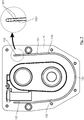
- FIG 3 is an exploded perspective view of a gearbox of a motor hoe according to one embodiment of the invention.
- the tiller includes preferably, a frame (not shown) supporting the gearbox 608 according to the invention, a transport wheel and two soil working tools (not shown) mounted in rotation under the frame around a transverse shaft 605 moved by a chain 606 disposed in a housing, the two cheeks of which are referenced 607 on the figure 1 .
- the chain 606 is driven by the axis of a pulley, called a receiver, 600 located at the rear of the frame, above the latter.
- the receiving pulley 600 is itself driven by a heat engine, located at the front of the chassis, the motor output shaft carrying a motor pulley 610 which is connected to the receiving pulley 600 by a clutch belt 609.
- the receiving pulley 600 is in conjunction with the gearbox 608 and the tools.
- the output shaft 23 of the 608 gearbox can be seen on the figure 1 .
- the gearbox 608 comprises a casing formed of two half-shells, namely a left half-shell 10 and a right-hand half-shell 9.
- the lateral half-shells 9, 10 are assembled according to a vertical junction plane, unlike the casings of the prior art gearboxes which include an upper half-shell and a lower half-shell assembled according to a junction plane. horizontal.
- the two half-shells 9, 10 of the casing are made of injected plastic (such as polyamide or polyamide reinforced with glass fibers), and not of aluminum as for the shells of the prior art.
- the gearbox housing 608 is therefore light, inexpensive to manufacture, and yet strong enough to support the shafts and meshes.
- the half-shells 9, 10 are secured to one another by means of screws 14 which are inserted directly into the plastic constituting these half-shells.
- the input 21 and output 23 shafts are parallel and extend in a horizontal plane.
- the gearbox 608 provides a forward speed and a reverse speed.
- the input shaft 21 is carried at each of its ends by a bearing 18, 19. On this input shaft 21 are mounted a sliding pinion 11 and an idle pinion 3.
- the output shaft 23 is carried at each of its ends by a bearing 18, 19. On the output shaft 23 are mounted the forward gear 90 and the reverse gear 100 which have different diameters and which are spaced by a spacer 8.
- the pinions of the gearbox 608 are preferably made by sintering steel powder, and are therefore economical to manufacture.
- the input shaft 21 is moved by the drive motor of the tiller and drives the output shaft 23 via the chain 20.
- the gearbox 608 is configured so that the sliding pinion 11 can occupy two distinct positions along the input shaft 21: a forward position, in which a first transmission ratio is achieved between the shaft d. 'input 21 and output shaft 23, the shafts 21, 23 rotating in the same direction of rotation, and a reverse position, in which a second transmission ratio is achieved between the input shaft 21 and the 'output shaft 23, the shafts 21, 23 rotating in opposite directions of rotation.
- the forward gear 90 cooperates with the idler gear 3 by means of a chain 20 in the forward gear position (sectional view of the figure 5 ), and the reverse gear 100 is adapted to cooperate with the sliding gear 11 when the latter is in the reverse gear position.
- the pinions necessary for operation in reverse gear in this case the sliding pinion 11 and the reverse gear 100, only work (or are “active”) when reverse gear is selected.
- the transmission ratio change is effected by means of a control cable C connected to a control handle P arranged, for example, on the operating handlebar of the equipment ( figure 4 ).
- the control cable C is connected to a lifter 5 actuator integral with a fork 4 which acts directly on the sliding pinion 11 to move it along the input shaft 21, between a position where it cooperates with the pinion 10 reverse gear (in the reverse gear position) and a position where it does not cooperate with any pinion of the output shaft 23 (in the forward gear position shown in figure figure 5 ).
- the lifter 5 takes the form of a rod, the central portion of which is cylindrical and is mounted fixedly on the fork 4, the assembly being mounted movable in rotation within the housing so that an action by a user on the control handle P drives the rotation of the rudder bar 5 and of the fork 4, and therefore the displacement of the sliding pinion 11 and its meshing with the reverse gear 100.
- this lifter taking the form of a rod, extends in a plane transverse to the vertical junction plane of the two half-shells 9, 10 of the gearbox 608.
- the lifter 5 extends in a plane parallel to the axes of the input 21 and output 23 shafts.
- the upper end of the fork 4 has a stud 41 which is housed in a slot or slot 51 of the lifter 5 ( figure 4 ).
- the latter is mounted by simple gravity above the fork 4 and extends on either side of the stud 41.
- the axis of rotation of the spreader bar 5 and of the fork 4 is vertical, and orthogonal to the axes of the input shafts 21 and output 23.
- the spacers 7 are pressed onto the upper and lower studs 41 of the fork 4. These spacers take the form of rings having a slot for passage of the studs 41 of the fork 4.
- the lifter 5 extends partly inside the casing and is pivotally mounted inside the latter.
- the cylindrical central portion of the lifter 5 and the lower spacer 7 are housed in semi-cylindrical housings 22 formed in the walls of the half-shells 9, 10.
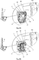
- the ends of the lifter 5 extend laterally through an opening 17 made in the half-shells 9, 10 of the housing ( figures 6A and 6B ) so that a user can actuate the lifter 5, and therefore the control fork 1, by operating the control handle P.
- openings 17 for the passage of the ends of the lifter 5 do not require a seal and allow the internal space of the casing to be vented.
- the sealing of the casing is therefore not total, unlike the casings of the prior art which require complete sealing to prevent oil leaks and present risks of overpressure.
- the change from forward to reverse gear is obtained by moving the control handle P, which itself drives the rotational movement of the rudder bar 5 by means of the control cable C, then of the fork 4, of so as to position the sliding pinion 11 in a position defining the transmission ratio between the input shaft 21 and the output shaft 23.
- a first end of the lifter 5 is secured to the control cable C by means of a spring 6B.
- the second end of the lifter 5, opposite the first end, is secured to a return spring 6A to allow the return of the fork 4 (and therefore of the lifter 5) in its initial position, that is to say in position forward, the return spring 6A being secured to the outer surface of the casing, and in particular of the half-shell 9.
- the lifter 5 has at its ends passage holes intended to hook the springs 6A, 6B.
- the invention thus proposes a motor hoe with a tool rotation inverter which is reliable and economical.
- Stops 12 provided in each of the half-shells allow the stop in rotation of the fork 4, and therefore of the translation of the sliding pinion 11.
- the nose 42 of the fork is able to come into contact with these stops 12 of the fork. This prevents unwanted plastic deformation, or matting, of the half-shells under the effect of shocks, and wear of the fork 4.
- crankcase allows the implementation of a bed of grease around the chain and sprockets, as well as between the latter and the internal walls of the crankcase (unlike conventional gearboxes that use oil inside the crankcase, which requires that the crankcase be drained when necessary).
- the sealing of the housing, and in particular of the assembly between the half-shells 9 and 10 is ensured by the implementation of O-rings 13 in "U" which are arranged on the interior surfaces of the half-shells 9 and 10, the base of the "U” being located in the lower part of the half-shells 9 and 10.
- the O-ring 13 is housed in a "U" -shaped groove 131 formed on the inner junction surface of the half-shell 10.
- the plating face of the left-hand half-shell 9 is for its part perfectly flat and smooth so as to ensure the crushing of the O-ring 13 during the screwed assembly of the half-shells 9 and 10.
- the cylindrical O-ring 13 is made of a material of the nitrile type, for example, or of another suitable material.
- Maintaining the seal 13 in the corresponding groove 131 may be provided by one or more locking teeth 1321.
- five sets 132 of three locking teeth 1321 are formed in the U-shaped groove 131 of the half-shell 10.
- This sealing solution is advantageous in that it allows easy assembly of the seal, easy dismantling of the gearbox housing during maintenance or repair operations during the life of the product, and this without degrading the level of tightness.
- the vent is provided by the opening 17 for passage of the lifter 5 made in each of the half-shells 9, 10. This makes it possible to avoid adding a hole and a vent plug. Because the passage opening 17 is made in the upper part of the half-shells, the grease cannot escape from the housing.
- the figure 5 is a sectional view in a vertical plane of the gearbox 608 showing the positioning of the fork 4 on the sliding pinion 11.
- the figures 6A and 6B show the mounting by screwing the gearbox 608 (with and without the half-shell 10) directly on the internal cover 609 of the tiller, on which is then mounted a protective cover (not shown).
- the tiller as described in the present application can be implemented with a gearbox of a type different from that shown in the appended figures.
- a gearbox according to the invention can have a different internal architecture.
- the input and output shafts can be coaxial and the gearbox can have a different number of speeds, and in particular two or more forward gears.
Landscapes
- Engineering & Computer Science (AREA)
- General Engineering & Computer Science (AREA)
- Mechanical Engineering (AREA)
- Soil Working Implements (AREA)
- General Details Of Gearings (AREA)
- Gear-Shifting Mechanisms (AREA)
- Transmission Devices (AREA)
Claims (10)
- Getriebe (608) für eine motorisierte landwirtschaftliche Ausrüstung, das dazu bestimmt ist, Motormittel mit Antriebsorganen der Ausrüstung zu verbinden, wobei das Getriebe (608) Folgendes umfasst:- ein Gehäuse des Getriebes (608),- eine Antriebswelle (21), die dazu geeignet ist, von den Motormitteln drehend angetrieben zu werden,- eine Abtriebswelle (23), die dazu geeignet ist, die Antriebsorgane der Ausrüstung anzutreiben,- ein als Schieberad (11) bezeichnetes Rad, das beweglich auf der Antriebswelle (21) montiert und dazu geeignet ist, zumindest eine Vorwärtslaufposition einzunehmen, in der ein erstes Übersetzungsverhältnis zwischen der Antriebswelle und der Abtriebswelle vorliegt, wobei sich die Wellen in derselben Drehrichtung drehen, und zumindest eine Rückwärtslaufposition einzunehmen, in der ein zweites Übersetzungsverhältnis zwischen der Antriebswelle und der Abtriebswelle vorliegt, wobei sich die Wellen in entgegengesetzte Drehrichtungen drehen,- eine bewegliche Gabel (4), die sich im Inneren des Gehäuses des Getriebes (608) erstreckt und dazu geeignet ist, mit dem Schieberad (11) zusammenzuwirken und durch seine Bewegung eine Änderung des Übersetzungsverhältnisses zwischen der Antriebswelle (21) und der Abtriebswelle (23) zu ermöglichen,dadurch gekennzeichnet, dass es außerdem einen Balken (5) zur Steuerung der Bewegung der Gabel (4) aufweist, der die Form einer Stange aufweist, deren mittlerer Teil zylindrisch ist und die fest an der Gabel (4) montiert ist, wobei sich der Balken (5) teilweise innerhalb des Gehäuses des Getriebes (608) erstreckt und ein erstes Ende und ein zweites Ende umfasst, wobei das erste Ende des Balkens (5) dazu geeignet ist, mit einem Steuerkabel (C) verbunden zu sein, so dass eine Beanspruchung des Steuerkabels (C) eine Änderung des Übersetzungsverhältnisses bewirkt.
- Getriebe (608) nach Anspruch 1, dadurch gekennzeichnet, dass die Baugruppe aus Balken (5) und Gabel (4) um eine vertikale Achse im Inneren des Gehäuses des Getriebes (608) drehbar montiert ist, wobei sich die Antriebs- (21) und die Abtriebswelle (23) horizontal erstrecken.
- Getriebe (608) nach Anspruch 1 oder 2, dadurch gekennzeichnet, dass das Gehäuse des Getriebes (608) aus zwei Halbschalen ausgebildet ist, die als linke Halbschale (9) bzw. rechte Halbschale (10) bezeichnet werden, einander in einer vertikalen Verbindungsebene gegenüberliegend angeordnet sind und eine Aufnahme der Wellen (21, 23), des Schieberads (12), eines Teils des Balkens (5) und insbesondere der Gabel (1) bilden, wobei die Halbschalen (9, 10) aus spritzgegossenem Kunststoff hergestellt sind.
- Getriebe (608) nach Anspruch 3, dadurch gekennzeichnet, dass sich das erste Ende des Balkens (5) durch eine in einer ersten der Halbschalen (9, 10) vorgesehene seitliche Öffnung (40) erstreckt.
- Getriebe (608) nach Anspruch 4, dadurch gekennzeichnet, dass sich das zweite Ende des Balkens (5) durch eine in der zweiten der Halbschalen (9, 10) vorgesehene seitliche Öffnung (40) erstreckt.
- Getriebe (608) nach Anspruch 4 oder 5, dadurch gekennzeichnet, dass die Öffnung(en) (40) so dimensioniert sind, dass die Luft zwischen dem Gehäuseinneren und -äußeren passieren kann.
- Getriebe (608) nach Anspruch 5 oder 6, dadurch gekennzeichnet, dass das zweite Ende des Balkens (5) mittels einer Rückstellfeder fest mit der Außenfläche einer der Halbschalen (9, 10) verbunden ist.
- Getriebe (608) nach einem der Ansprüche 3 bis 7, dadurch gekennzeichnet, dass die beiden Halbschalen (9, 10) mit Hilfe von reversiblen Verbindungsmitteln zusammengefügt sind, wobei jede der Halbschalen (9, 10) an ihrer Verbindungsfläche mit der anderen Halbschale (9, 10) eine Dichtung (13) umfasst.
- Motorisierte landwirtschaftliche Ausrüstung, dadurch gekennzeichnet, dass sie ein Getriebe (608) nach einem der Ansprüche 1 bis 8 umfasst.
- Ausrüstung nach Anspruch 9, dadurch gekennzeichnet, dass sie einen Steuergriff (P) und ein Steuerkabel (C), das den Steuergriff (50) mit einem ersten Ende des Balkens (5) verbindet, umfasst, so dass eine Beanspruchung des Steuergriffs (P) eine Änderung des Übersetzungsverhältnisses bewirkt.
Applications Claiming Priority (2)
| Application Number | Priority Date | Filing Date | Title |
|---|---|---|---|
| FR1754436A FR3066575B1 (fr) | 2017-05-19 | 2017-05-19 | Boite de vitesses pour equipement de motoculture et equipement de motoculture comprenant une telle boite de vitesses |
| PCT/EP2018/062582 WO2018210855A1 (fr) | 2017-05-19 | 2018-05-15 | Boîte de vitesses pour équipement de motoculture et équipement de motoculture comprenant une telle boîte de vitesses |
Publications (2)
| Publication Number | Publication Date |
|---|---|
| EP3625481A1 EP3625481A1 (de) | 2020-03-25 |
| EP3625481B1 true EP3625481B1 (de) | 2021-02-17 |
Family
ID=60765671
Family Applications (1)
| Application Number | Title | Priority Date | Filing Date |
|---|---|---|---|
| EP18725187.1A Active EP3625481B1 (de) | 2017-05-19 | 2018-05-15 | Getriebe für eine mechanisierte landwirtschaftliche vorrichtung und mechanisierte landwirtschaftliche vorrichtung mit einem derartigen getriebe |
Country Status (7)
| Country | Link |
|---|---|
| EP (1) | EP3625481B1 (de) |
| CN (1) | CN110520655B (de) |
| ES (1) | ES2864682T3 (de) |
| FR (1) | FR3066575B1 (de) |
| PT (1) | PT3625481T (de) |
| RU (1) | RU2748922C2 (de) |
| WO (1) | WO2018210855A1 (de) |
Family Cites Families (14)
| Publication number | Priority date | Publication date | Assignee | Title |
|---|---|---|---|---|
| JPS5232645Y2 (de) * | 1973-10-29 | 1977-07-26 | ||
| SU1025570A1 (ru) * | 1975-09-30 | 1983-06-30 | Meladze Radeli D | Трактор |
| SU1595733A1 (ru) * | 1988-11-23 | 1990-09-30 | Кутаисский политехнический институт им.Н.И.Мусхелишвили | Устройство штангового управлени мотоблока |
| JP2933268B2 (ja) * | 1995-01-23 | 1999-08-09 | 三菱農機株式会社 | 耕うん機における変速ガイド板構造 |
| JPH10287141A (ja) * | 1997-04-14 | 1998-10-27 | Mitsubishi Agricult Mach Co Ltd | 歩行型移動農機 |
| CN200975422Y (zh) * | 2006-11-23 | 2007-11-14 | 曹蜀立 | 牙嵌离合器 |
| CN101015238A (zh) * | 2007-02-05 | 2007-08-15 | 重庆耕福机械制造有限公司 | 自走式微型旋耕机 |
| CN201047421Y (zh) * | 2007-05-11 | 2008-04-16 | 孙定忠 | 微耕机双排齿轮传动机构 |
| JP2011087476A (ja) * | 2009-10-20 | 2011-05-06 | Mitsubishi Agricult Mach Co Ltd | 耕耘装置 |
| FR2965878B1 (fr) * | 2010-10-12 | 2012-11-16 | Pubert Henri Sas | Boite de vitesses pour equipement de motoculture et equipement de motoculture comprenant une telle boite de vitesses |
| FR2966536B1 (fr) * | 2010-10-25 | 2012-10-26 | France Reducteurs | Boitier de mecanisme de transmission, notamment pour une transmission entre un arbre primaire moteur et un arbre de sortie |
| US9651138B2 (en) * | 2011-09-30 | 2017-05-16 | Mtd Products Inc. | Speed control assembly for a self-propelled walk-behind lawn mower |
| JP6228163B2 (ja) * | 2015-06-11 | 2017-11-08 | トヨタ自動車株式会社 | 車両用手動変速機 |
| FR3042569B1 (fr) * | 2015-10-20 | 2017-12-08 | Pubert Henri Sas | Boite de vitesses pour equipement de motoculture et equipement de motoculture comprenant une telle boite de vitesses. |
-
2017
- 2017-05-19 FR FR1754436A patent/FR3066575B1/fr active Active
-
2018
- 2018-05-15 WO PCT/EP2018/062582 patent/WO2018210855A1/fr not_active Ceased
- 2018-05-15 RU RU2019136821A patent/RU2748922C2/ru active
- 2018-05-15 CN CN201880025010.7A patent/CN110520655B/zh active Active
- 2018-05-15 PT PT187251871T patent/PT3625481T/pt unknown
- 2018-05-15 EP EP18725187.1A patent/EP3625481B1/de active Active
- 2018-05-15 ES ES18725187T patent/ES2864682T3/es active Active
Non-Patent Citations (1)
| Title |
|---|
| None * |
Also Published As
| Publication number | Publication date |
|---|---|
| EP3625481A1 (de) | 2020-03-25 |
| RU2019136821A3 (de) | 2021-05-18 |
| PT3625481T (pt) | 2021-03-12 |
| CN110520655A (zh) | 2019-11-29 |
| RU2748922C2 (ru) | 2021-06-01 |
| FR3066575A1 (fr) | 2018-11-23 |
| CN110520655B (zh) | 2021-05-07 |
| WO2018210855A1 (fr) | 2018-11-22 |
| RU2019136821A (ru) | 2021-05-18 |
| ES2864682T3 (es) | 2021-10-14 |
| FR3066575B1 (fr) | 2020-08-28 |
Similar Documents
| Publication | Publication Date | Title |
|---|---|---|
| FR3053007B1 (fr) | Transmission, notamment pour engin roulant, et engin roulant equipe d'une telle transmission | |
| EP3143852B1 (de) | Ausstattung für motorisierte landmaschine | |
| FR2975367A1 (fr) | Dispositif de changement de vitesses pour velos | |
| CA1102221A (fr) | Faucheuse a disques entraines par le bas | |
| FR2460221A1 (fr) | Dispositif de prise de force pour tracteur | |
| FR2463042A1 (fr) | Motoculteur du type a moteur vertical | |
| EP2627928B1 (de) | Getriebe für eine motorisierte landwirtschaftliche vorrichtung und motorisierte landwirtschaftliche vorrichtung mit einem derartigen getriebe | |
| FR2617446A1 (fr) | Systeme de transmission de puissance dans un tracteur | |
| WO2014106714A1 (fr) | Boîte de vitesses pour engin automoteur, tel que tondeuse à gazon | |
| FR2882304A1 (fr) | Transmission pour tracteur | |
| EP3159579B1 (de) | Getriebe für ausrüstung einer motorisierten landmaschine, und ausrüstung für motorisierte landmaschine, die ein solches getriebe umfasst | |
| FR2586774A1 (fr) | Transmission et changement de vitesse pour tracteur agricole, par engrenage de deplacement, notamment pour tondeuse a gazon | |
| FR2556661A1 (fr) | Transmission pour tracteur avec arbre de prise de force | |
| WO2018210855A1 (fr) | Boîte de vitesses pour équipement de motoculture et équipement de motoculture comprenant une telle boîte de vitesses | |
| EP1775498B1 (de) | Getriebe für motorisiertes landwirtschaftliches Arbeitsgerät | |
| EP2273155B1 (de) | Getriebe für eine selbstfahrende Ackerfräse und Ackerfräse mit entsprechendem Getriebe | |
| FR2553486A1 (fr) | Dispositif de transmission pour vehicules utilitaires tels que tondeuses a gazon | |
| FR3056075B1 (fr) | Motobineuse | |
| FR2525712A1 (fr) | Mecanisme de securite pour engrenages de reduction | |
| FR3093157A1 (fr) | Ensemble de marche arriere et boite de vitesses comprenant un tel ensemble | |
| FR2538475A1 (fr) | Perfectionnement aux boites ponts pour motoculteurs et engins analogues | |
| FR3079901A1 (fr) | Boite de transmission mecanique pour equipement de motoculture, et procede d'assemblage correspondant | |
| FR2892167A1 (fr) | Boite de vitesse pneumatique pour equipement de motoculture | |
| WO2019192790A1 (fr) | Equipement de motoculture | |
| EP1669592A1 (de) | Anlassvorrichtung einer Brennkraftmaschine |
Legal Events
| Date | Code | Title | Description |
|---|---|---|---|
| STAA | Information on the status of an ep patent application or granted ep patent |
Free format text: STATUS: UNKNOWN |
|
| STAA | Information on the status of an ep patent application or granted ep patent |
Free format text: STATUS: THE INTERNATIONAL PUBLICATION HAS BEEN MADE |
|
| PUAI | Public reference made under article 153(3) epc to a published international application that has entered the european phase |
Free format text: ORIGINAL CODE: 0009012 |
|
| STAA | Information on the status of an ep patent application or granted ep patent |
Free format text: STATUS: REQUEST FOR EXAMINATION WAS MADE |
|
| 17P | Request for examination filed |
Effective date: 20190917 |
|
| AK | Designated contracting states |
Kind code of ref document: A1 Designated state(s): AL AT BE BG CH CY CZ DE DK EE ES FI FR GB GR HR HU IE IS IT LI LT LU LV MC MK MT NL NO PL PT RO RS SE SI SK SM TR |
|
| AX | Request for extension of the european patent |
Extension state: BA ME |
|
| DAV | Request for validation of the european patent (deleted) | ||
| DAX | Request for extension of the european patent (deleted) | ||
| GRAP | Despatch of communication of intention to grant a patent |
Free format text: ORIGINAL CODE: EPIDOSNIGR1 |
|
| STAA | Information on the status of an ep patent application or granted ep patent |
Free format text: STATUS: GRANT OF PATENT IS INTENDED |
|
| INTG | Intention to grant announced |
Effective date: 20201204 |
|
| GRAS | Grant fee paid |
Free format text: ORIGINAL CODE: EPIDOSNIGR3 |
|
| GRAA | (expected) grant |
Free format text: ORIGINAL CODE: 0009210 |
|
| STAA | Information on the status of an ep patent application or granted ep patent |
Free format text: STATUS: THE PATENT HAS BEEN GRANTED |
|
| AK | Designated contracting states |
Kind code of ref document: B1 Designated state(s): AL AT BE BG CH CY CZ DE DK EE ES FI FR GB GR HR HU IE IS IT LI LT LU LV MC MK MT NL NO PL PT RO RS SE SI SK SM TR |
|
| REG | Reference to a national code |
Ref country code: GB Ref legal event code: FG4D Free format text: NOT ENGLISH |
|
| REG | Reference to a national code |
Ref country code: CH Ref legal event code: EP |
|
| REG | Reference to a national code |
Ref country code: DE Ref legal event code: R096 Ref document number: 602018012719 Country of ref document: DE |
|
| REG | Reference to a national code |
Ref country code: PT Ref legal event code: SC4A Ref document number: 3625481 Country of ref document: PT Date of ref document: 20210312 Kind code of ref document: T Free format text: AVAILABILITY OF NATIONAL TRANSLATION Effective date: 20210305 |
|
| REG | Reference to a national code |
Ref country code: AT Ref legal event code: REF Ref document number: 1361893 Country of ref document: AT Kind code of ref document: T Effective date: 20210315 |
|
| REG | Reference to a national code |
Ref country code: IE Ref legal event code: FG4D Free format text: LANGUAGE OF EP DOCUMENT: FRENCH |
|
| REG | Reference to a national code |
Ref country code: LT Ref legal event code: MG9D |
|
| REG | Reference to a national code |
Ref country code: NL Ref legal event code: MP Effective date: 20210217 |
|
| PG25 | Lapsed in a contracting state [announced via postgrant information from national office to epo] |
Ref country code: LT Free format text: LAPSE BECAUSE OF FAILURE TO SUBMIT A TRANSLATION OF THE DESCRIPTION OR TO PAY THE FEE WITHIN THE PRESCRIBED TIME-LIMIT Effective date: 20210217 Ref country code: NO Free format text: LAPSE BECAUSE OF FAILURE TO SUBMIT A TRANSLATION OF THE DESCRIPTION OR TO PAY THE FEE WITHIN THE PRESCRIBED TIME-LIMIT Effective date: 20210517 Ref country code: HR Free format text: LAPSE BECAUSE OF FAILURE TO SUBMIT A TRANSLATION OF THE DESCRIPTION OR TO PAY THE FEE WITHIN THE PRESCRIBED TIME-LIMIT Effective date: 20210217 Ref country code: GR Free format text: LAPSE BECAUSE OF FAILURE TO SUBMIT A TRANSLATION OF THE DESCRIPTION OR TO PAY THE FEE WITHIN THE PRESCRIBED TIME-LIMIT Effective date: 20210518 Ref country code: FI Free format text: LAPSE BECAUSE OF FAILURE TO SUBMIT A TRANSLATION OF THE DESCRIPTION OR TO PAY THE FEE WITHIN THE PRESCRIBED TIME-LIMIT Effective date: 20210217 Ref country code: BG Free format text: LAPSE BECAUSE OF FAILURE TO SUBMIT A TRANSLATION OF THE DESCRIPTION OR TO PAY THE FEE WITHIN THE PRESCRIBED TIME-LIMIT Effective date: 20210517 |
|
| REG | Reference to a national code |
Ref country code: AT Ref legal event code: MK05 Ref document number: 1361893 Country of ref document: AT Kind code of ref document: T Effective date: 20210217 |
|
| PG25 | Lapsed in a contracting state [announced via postgrant information from national office to epo] |
Ref country code: LV Free format text: LAPSE BECAUSE OF FAILURE TO SUBMIT A TRANSLATION OF THE DESCRIPTION OR TO PAY THE FEE WITHIN THE PRESCRIBED TIME-LIMIT Effective date: 20210217 Ref country code: PL Free format text: LAPSE BECAUSE OF FAILURE TO SUBMIT A TRANSLATION OF THE DESCRIPTION OR TO PAY THE FEE WITHIN THE PRESCRIBED TIME-LIMIT Effective date: 20210217 Ref country code: RS Free format text: LAPSE BECAUSE OF FAILURE TO SUBMIT A TRANSLATION OF THE DESCRIPTION OR TO PAY THE FEE WITHIN THE PRESCRIBED TIME-LIMIT Effective date: 20210217 Ref country code: NL Free format text: LAPSE BECAUSE OF FAILURE TO SUBMIT A TRANSLATION OF THE DESCRIPTION OR TO PAY THE FEE WITHIN THE PRESCRIBED TIME-LIMIT Effective date: 20210217 Ref country code: SE Free format text: LAPSE BECAUSE OF FAILURE TO SUBMIT A TRANSLATION OF THE DESCRIPTION OR TO PAY THE FEE WITHIN THE PRESCRIBED TIME-LIMIT Effective date: 20210217 |
|
| PG25 | Lapsed in a contracting state [announced via postgrant information from national office to epo] |
Ref country code: IS Free format text: LAPSE BECAUSE OF FAILURE TO SUBMIT A TRANSLATION OF THE DESCRIPTION OR TO PAY THE FEE WITHIN THE PRESCRIBED TIME-LIMIT Effective date: 20210617 |
|
| REG | Reference to a national code |
Ref country code: ES Ref legal event code: FG2A Ref document number: 2864682 Country of ref document: ES Kind code of ref document: T3 Effective date: 20211014 |
|
| PG25 | Lapsed in a contracting state [announced via postgrant information from national office to epo] |
Ref country code: SM Free format text: LAPSE BECAUSE OF FAILURE TO SUBMIT A TRANSLATION OF THE DESCRIPTION OR TO PAY THE FEE WITHIN THE PRESCRIBED TIME-LIMIT Effective date: 20210217 Ref country code: AT Free format text: LAPSE BECAUSE OF FAILURE TO SUBMIT A TRANSLATION OF THE DESCRIPTION OR TO PAY THE FEE WITHIN THE PRESCRIBED TIME-LIMIT Effective date: 20210217 Ref country code: CZ Free format text: LAPSE BECAUSE OF FAILURE TO SUBMIT A TRANSLATION OF THE DESCRIPTION OR TO PAY THE FEE WITHIN THE PRESCRIBED TIME-LIMIT Effective date: 20210217 Ref country code: EE Free format text: LAPSE BECAUSE OF FAILURE TO SUBMIT A TRANSLATION OF THE DESCRIPTION OR TO PAY THE FEE WITHIN THE PRESCRIBED TIME-LIMIT Effective date: 20210217 |
|
| REG | Reference to a national code |
Ref country code: DE Ref legal event code: R097 Ref document number: 602018012719 Country of ref document: DE |
|
| PG25 | Lapsed in a contracting state [announced via postgrant information from national office to epo] |
Ref country code: DK Free format text: LAPSE BECAUSE OF FAILURE TO SUBMIT A TRANSLATION OF THE DESCRIPTION OR TO PAY THE FEE WITHIN THE PRESCRIBED TIME-LIMIT Effective date: 20210217 Ref country code: SK Free format text: LAPSE BECAUSE OF FAILURE TO SUBMIT A TRANSLATION OF THE DESCRIPTION OR TO PAY THE FEE WITHIN THE PRESCRIBED TIME-LIMIT Effective date: 20210217 Ref country code: RO Free format text: LAPSE BECAUSE OF FAILURE TO SUBMIT A TRANSLATION OF THE DESCRIPTION OR TO PAY THE FEE WITHIN THE PRESCRIBED TIME-LIMIT Effective date: 20210217 |
|
| PLBE | No opposition filed within time limit |
Free format text: ORIGINAL CODE: 0009261 |
|
| STAA | Information on the status of an ep patent application or granted ep patent |
Free format text: STATUS: NO OPPOSITION FILED WITHIN TIME LIMIT |
|
| REG | Reference to a national code |
Ref country code: CH Ref legal event code: PL |
|
| 26N | No opposition filed |
Effective date: 20211118 |
|
| PG25 | Lapsed in a contracting state [announced via postgrant information from national office to epo] |
Ref country code: CH Free format text: LAPSE BECAUSE OF NON-PAYMENT OF DUE FEES Effective date: 20210531 Ref country code: AL Free format text: LAPSE BECAUSE OF FAILURE TO SUBMIT A TRANSLATION OF THE DESCRIPTION OR TO PAY THE FEE WITHIN THE PRESCRIBED TIME-LIMIT Effective date: 20210217 Ref country code: LI Free format text: LAPSE BECAUSE OF NON-PAYMENT OF DUE FEES Effective date: 20210531 Ref country code: LU Free format text: LAPSE BECAUSE OF NON-PAYMENT OF DUE FEES Effective date: 20210515 Ref country code: MC Free format text: LAPSE BECAUSE OF FAILURE TO SUBMIT A TRANSLATION OF THE DESCRIPTION OR TO PAY THE FEE WITHIN THE PRESCRIBED TIME-LIMIT Effective date: 20210217 |
|
| REG | Reference to a national code |
Ref country code: BE Ref legal event code: MM Effective date: 20210531 |
|
| PG25 | Lapsed in a contracting state [announced via postgrant information from national office to epo] |
Ref country code: SI Free format text: LAPSE BECAUSE OF FAILURE TO SUBMIT A TRANSLATION OF THE DESCRIPTION OR TO PAY THE FEE WITHIN THE PRESCRIBED TIME-LIMIT Effective date: 20210217 |
|
| PG25 | Lapsed in a contracting state [announced via postgrant information from national office to epo] |
Ref country code: IE Free format text: LAPSE BECAUSE OF NON-PAYMENT OF DUE FEES Effective date: 20210515 |
|
| PG25 | Lapsed in a contracting state [announced via postgrant information from national office to epo] |
Ref country code: IS Free format text: LAPSE BECAUSE OF FAILURE TO SUBMIT A TRANSLATION OF THE DESCRIPTION OR TO PAY THE FEE WITHIN THE PRESCRIBED TIME-LIMIT Effective date: 20210617 |
|
| PG25 | Lapsed in a contracting state [announced via postgrant information from national office to epo] |
Ref country code: BE Free format text: LAPSE BECAUSE OF NON-PAYMENT OF DUE FEES Effective date: 20210531 |
|
| GBPC | Gb: european patent ceased through non-payment of renewal fee |
Effective date: 20220515 |
|
| PG25 | Lapsed in a contracting state [announced via postgrant information from national office to epo] |
Ref country code: GB Free format text: LAPSE BECAUSE OF NON-PAYMENT OF DUE FEES Effective date: 20220515 |
|
| P01 | Opt-out of the competence of the unified patent court (upc) registered |
Effective date: 20230517 |
|
| PG25 | Lapsed in a contracting state [announced via postgrant information from national office to epo] |
Ref country code: CY Free format text: LAPSE BECAUSE OF FAILURE TO SUBMIT A TRANSLATION OF THE DESCRIPTION OR TO PAY THE FEE WITHIN THE PRESCRIBED TIME-LIMIT Effective date: 20210217 |
|
| PG25 | Lapsed in a contracting state [announced via postgrant information from national office to epo] |
Ref country code: HU Free format text: LAPSE BECAUSE OF FAILURE TO SUBMIT A TRANSLATION OF THE DESCRIPTION OR TO PAY THE FEE WITHIN THE PRESCRIBED TIME-LIMIT; INVALID AB INITIO Effective date: 20180515 |
|
| PG25 | Lapsed in a contracting state [announced via postgrant information from national office to epo] |
Ref country code: MK Free format text: LAPSE BECAUSE OF FAILURE TO SUBMIT A TRANSLATION OF THE DESCRIPTION OR TO PAY THE FEE WITHIN THE PRESCRIBED TIME-LIMIT Effective date: 20210217 |
|
| PG25 | Lapsed in a contracting state [announced via postgrant information from national office to epo] |
Ref country code: MT Free format text: LAPSE BECAUSE OF FAILURE TO SUBMIT A TRANSLATION OF THE DESCRIPTION OR TO PAY THE FEE WITHIN THE PRESCRIBED TIME-LIMIT Effective date: 20210217 |
|
| PGFP | Annual fee paid to national office [announced via postgrant information from national office to epo] |
Ref country code: DE Payment date: 20250527 Year of fee payment: 8 |
|
| PGFP | Annual fee paid to national office [announced via postgrant information from national office to epo] |
Ref country code: ES Payment date: 20250605 Year of fee payment: 8 |
|
| PGFP | Annual fee paid to national office [announced via postgrant information from national office to epo] |
Ref country code: IT Payment date: 20250411 Year of fee payment: 8 |
|
| PGFP | Annual fee paid to national office [announced via postgrant information from national office to epo] |
Ref country code: PT Payment date: 20250430 Year of fee payment: 8 |
|
| PGFP | Annual fee paid to national office [announced via postgrant information from national office to epo] |
Ref country code: FR Payment date: 20250523 Year of fee payment: 8 |
|
| PGFP | Annual fee paid to national office [announced via postgrant information from national office to epo] |
Ref country code: TR Payment date: 20260305 Year of fee payment: 9 |