EP3625035B1 - Ensemble galet de soudage - Google Patents
Ensemble galet de soudage Download PDFInfo
- Publication number
- EP3625035B1 EP3625035B1 EP18727188.7A EP18727188A EP3625035B1 EP 3625035 B1 EP3625035 B1 EP 3625035B1 EP 18727188 A EP18727188 A EP 18727188A EP 3625035 B1 EP3625035 B1 EP 3625035B1
- Authority
- EP
- European Patent Office
- Prior art keywords
- roller electrode
- electrode arrangement
- frequency
- roller
- workpiece
- Prior art date
- Legal status (The legal status is an assumption and is not a legal conclusion. Google has not performed a legal analysis and makes no representation as to the accuracy of the status listed.)
- Active
Links
Images


Classifications
-
- B—PERFORMING OPERATIONS; TRANSPORTING
- B29—WORKING OF PLASTICS; WORKING OF SUBSTANCES IN A PLASTIC STATE IN GENERAL
- B29C—SHAPING OR JOINING OF PLASTICS; SHAPING OF MATERIAL IN A PLASTIC STATE, NOT OTHERWISE PROVIDED FOR; AFTER-TREATMENT OF THE SHAPED PRODUCTS, e.g. REPAIRING
- B29C65/00—Joining or sealing of preformed parts, e.g. welding of plastics materials; Apparatus therefor
- B29C65/02—Joining or sealing of preformed parts, e.g. welding of plastics materials; Apparatus therefor by heating, with or without pressure
- B29C65/04—Dielectric heating, e.g. high-frequency welding, i.e. radio frequency welding of plastic materials having dielectric properties, e.g. PVC
-
- B—PERFORMING OPERATIONS; TRANSPORTING
- B29—WORKING OF PLASTICS; WORKING OF SUBSTANCES IN A PLASTIC STATE IN GENERAL
- B29C—SHAPING OR JOINING OF PLASTICS; SHAPING OF MATERIAL IN A PLASTIC STATE, NOT OTHERWISE PROVIDED FOR; AFTER-TREATMENT OF THE SHAPED PRODUCTS, e.g. REPAIRING
- B29C65/00—Joining or sealing of preformed parts, e.g. welding of plastics materials; Apparatus therefor
- B29C65/48—Joining or sealing of preformed parts, e.g. welding of plastics materials; Apparatus therefor using adhesives, i.e. using supplementary joining material; solvent bonding
- B29C65/4805—Joining or sealing of preformed parts, e.g. welding of plastics materials; Apparatus therefor using adhesives, i.e. using supplementary joining material; solvent bonding characterised by the type of adhesives
- B29C65/481—Non-reactive adhesives, e.g. physically hardening adhesives
- B29C65/4815—Hot melt adhesives, e.g. thermoplastic adhesives
-
- B—PERFORMING OPERATIONS; TRANSPORTING
- B29—WORKING OF PLASTICS; WORKING OF SUBSTANCES IN A PLASTIC STATE IN GENERAL
- B29C—SHAPING OR JOINING OF PLASTICS; SHAPING OF MATERIAL IN A PLASTIC STATE, NOT OTHERWISE PROVIDED FOR; AFTER-TREATMENT OF THE SHAPED PRODUCTS, e.g. REPAIRING
- B29C65/00—Joining or sealing of preformed parts, e.g. welding of plastics materials; Apparatus therefor
- B29C65/78—Means for handling the parts to be joined, e.g. for making containers or hollow articles, e.g. means for handling sheets, plates, web-like materials, tubular articles, hollow articles or elements to be joined therewith; Means for discharging the joined articles from the joining apparatus
- B29C65/7858—Means for handling the parts to be joined, e.g. for making containers or hollow articles, e.g. means for handling sheets, plates, web-like materials, tubular articles, hollow articles or elements to be joined therewith; Means for discharging the joined articles from the joining apparatus characterised by the feeding movement of the parts to be joined
- B29C65/7888—Means for handling of moving sheets or webs
- B29C65/7894—Means for handling of moving sheets or webs of continuously moving sheets or webs
-
- B—PERFORMING OPERATIONS; TRANSPORTING
- B29—WORKING OF PLASTICS; WORKING OF SUBSTANCES IN A PLASTIC STATE IN GENERAL
- B29C—SHAPING OR JOINING OF PLASTICS; SHAPING OF MATERIAL IN A PLASTIC STATE, NOT OTHERWISE PROVIDED FOR; AFTER-TREATMENT OF THE SHAPED PRODUCTS, e.g. REPAIRING
- B29C66/00—General aspects of processes or apparatus for joining preformed parts
- B29C66/006—Preventing damaging, e.g. of the parts to be joined
-
- B—PERFORMING OPERATIONS; TRANSPORTING
- B29—WORKING OF PLASTICS; WORKING OF SUBSTANCES IN A PLASTIC STATE IN GENERAL
- B29C—SHAPING OR JOINING OF PLASTICS; SHAPING OF MATERIAL IN A PLASTIC STATE, NOT OTHERWISE PROVIDED FOR; AFTER-TREATMENT OF THE SHAPED PRODUCTS, e.g. REPAIRING
- B29C66/00—General aspects of processes or apparatus for joining preformed parts
- B29C66/01—General aspects dealing with the joint area or with the area to be joined
- B29C66/05—Particular design of joint configurations
- B29C66/10—Particular design of joint configurations particular design of the joint cross-sections
- B29C66/11—Joint cross-sections comprising a single joint-segment, i.e. one of the parts to be joined comprising a single joint-segment in the joint cross-section
- B29C66/112—Single lapped joints
- B29C66/1122—Single lap to lap joints, i.e. overlap joints
-
- B—PERFORMING OPERATIONS; TRANSPORTING
- B29—WORKING OF PLASTICS; WORKING OF SUBSTANCES IN A PLASTIC STATE IN GENERAL
- B29C—SHAPING OR JOINING OF PLASTICS; SHAPING OF MATERIAL IN A PLASTIC STATE, NOT OTHERWISE PROVIDED FOR; AFTER-TREATMENT OF THE SHAPED PRODUCTS, e.g. REPAIRING
- B29C66/00—General aspects of processes or apparatus for joining preformed parts
- B29C66/40—General aspects of joining substantially flat articles, e.g. plates, sheets or web-like materials; Making flat seams in tubular or hollow articles; Joining single elements to substantially flat surfaces
- B29C66/41—Joining substantially flat articles ; Making flat seams in tubular or hollow articles
- B29C66/43—Joining a relatively small portion of the surface of said articles
-
- B—PERFORMING OPERATIONS; TRANSPORTING
- B29—WORKING OF PLASTICS; WORKING OF SUBSTANCES IN A PLASTIC STATE IN GENERAL
- B29C—SHAPING OR JOINING OF PLASTICS; SHAPING OF MATERIAL IN A PLASTIC STATE, NOT OTHERWISE PROVIDED FOR; AFTER-TREATMENT OF THE SHAPED PRODUCTS, e.g. REPAIRING
- B29C66/00—General aspects of processes or apparatus for joining preformed parts
- B29C66/70—General aspects of processes or apparatus for joining preformed parts characterised by the composition, physical properties or the structure of the material of the parts to be joined; Joining with non-plastics material
- B29C66/71—General aspects of processes or apparatus for joining preformed parts characterised by the composition, physical properties or the structure of the material of the parts to be joined; Joining with non-plastics material characterised by the composition of the plastics material of the parts to be joined
- B29C66/712—General aspects of processes or apparatus for joining preformed parts characterised by the composition, physical properties or the structure of the material of the parts to be joined; Joining with non-plastics material characterised by the composition of the plastics material of the parts to be joined the composition of one of the parts to be joined being different from the composition of the other part
-
- B—PERFORMING OPERATIONS; TRANSPORTING
- B29—WORKING OF PLASTICS; WORKING OF SUBSTANCES IN A PLASTIC STATE IN GENERAL
- B29C—SHAPING OR JOINING OF PLASTICS; SHAPING OF MATERIAL IN A PLASTIC STATE, NOT OTHERWISE PROVIDED FOR; AFTER-TREATMENT OF THE SHAPED PRODUCTS, e.g. REPAIRING
- B29C66/00—General aspects of processes or apparatus for joining preformed parts
- B29C66/70—General aspects of processes or apparatus for joining preformed parts characterised by the composition, physical properties or the structure of the material of the parts to be joined; Joining with non-plastics material
- B29C66/73—General aspects of processes or apparatus for joining preformed parts characterised by the composition, physical properties or the structure of the material of the parts to be joined; Joining with non-plastics material characterised by the intensive physical properties of the material of the parts to be joined, by the optical properties of the material of the parts to be joined, by the extensive physical properties of the parts to be joined, by the state of the material of the parts to be joined or by the material of the parts to be joined being a thermoplastic or a thermoset
- B29C66/739—General aspects of processes or apparatus for joining preformed parts characterised by the composition, physical properties or the structure of the material of the parts to be joined; Joining with non-plastics material characterised by the intensive physical properties of the material of the parts to be joined, by the optical properties of the material of the parts to be joined, by the extensive physical properties of the parts to be joined, by the state of the material of the parts to be joined or by the material of the parts to be joined being a thermoplastic or a thermoset characterised by the material of the parts to be joined being a thermoplastic or a thermoset
- B29C66/7392—General aspects of processes or apparatus for joining preformed parts characterised by the composition, physical properties or the structure of the material of the parts to be joined; Joining with non-plastics material characterised by the intensive physical properties of the material of the parts to be joined, by the optical properties of the material of the parts to be joined, by the extensive physical properties of the parts to be joined, by the state of the material of the parts to be joined or by the material of the parts to be joined being a thermoplastic or a thermoset characterised by the material of the parts to be joined being a thermoplastic or a thermoset characterised by the material of at least one of the parts being a thermoplastic
- B29C66/73921—General aspects of processes or apparatus for joining preformed parts characterised by the composition, physical properties or the structure of the material of the parts to be joined; Joining with non-plastics material characterised by the intensive physical properties of the material of the parts to be joined, by the optical properties of the material of the parts to be joined, by the extensive physical properties of the parts to be joined, by the state of the material of the parts to be joined or by the material of the parts to be joined being a thermoplastic or a thermoset characterised by the material of the parts to be joined being a thermoplastic or a thermoset characterised by the material of at least one of the parts being a thermoplastic characterised by the materials of both parts being thermoplastics
-
- B—PERFORMING OPERATIONS; TRANSPORTING
- B29—WORKING OF PLASTICS; WORKING OF SUBSTANCES IN A PLASTIC STATE IN GENERAL
- B29C—SHAPING OR JOINING OF PLASTICS; SHAPING OF MATERIAL IN A PLASTIC STATE, NOT OTHERWISE PROVIDED FOR; AFTER-TREATMENT OF THE SHAPED PRODUCTS, e.g. REPAIRING
- B29C66/00—General aspects of processes or apparatus for joining preformed parts
- B29C66/80—General aspects of machine operations or constructions and parts thereof
- B29C66/81—General aspects of the pressing elements, i.e. the elements applying pressure on the parts to be joined in the area to be joined, e.g. the welding jaws or clamps
- B29C66/814—General aspects of the pressing elements, i.e. the elements applying pressure on the parts to be joined in the area to be joined, e.g. the welding jaws or clamps characterised by the design of the pressing elements, e.g. of the welding jaws or clamps
- B29C66/8145—General aspects of the pressing elements, i.e. the elements applying pressure on the parts to be joined in the area to be joined, e.g. the welding jaws or clamps characterised by the design of the pressing elements, e.g. of the welding jaws or clamps characterised by the constructional aspects of the pressing elements, e.g. of the welding jaws or clamps
- B29C66/81457—General aspects of the pressing elements, i.e. the elements applying pressure on the parts to be joined in the area to be joined, e.g. the welding jaws or clamps characterised by the design of the pressing elements, e.g. of the welding jaws or clamps characterised by the constructional aspects of the pressing elements, e.g. of the welding jaws or clamps comprising a block or layer of deformable material, e.g. sponge, foam, rubber
-
- B—PERFORMING OPERATIONS; TRANSPORTING
- B29—WORKING OF PLASTICS; WORKING OF SUBSTANCES IN A PLASTIC STATE IN GENERAL
- B29C—SHAPING OR JOINING OF PLASTICS; SHAPING OF MATERIAL IN A PLASTIC STATE, NOT OTHERWISE PROVIDED FOR; AFTER-TREATMENT OF THE SHAPED PRODUCTS, e.g. REPAIRING
- B29C66/00—General aspects of processes or apparatus for joining preformed parts
- B29C66/80—General aspects of machine operations or constructions and parts thereof
- B29C66/81—General aspects of the pressing elements, i.e. the elements applying pressure on the parts to be joined in the area to be joined, e.g. the welding jaws or clamps
- B29C66/818—General aspects of the pressing elements, i.e. the elements applying pressure on the parts to be joined in the area to be joined, e.g. the welding jaws or clamps characterised by the cooling constructional aspects, or by the thermal or electrical insulating or conducting constructional aspects of the welding jaws or of the clamps ; comprising means for compensating for the thermal expansion of the welding jaws or of the clamps
- B29C66/8187—General aspects of the pressing elements, i.e. the elements applying pressure on the parts to be joined in the area to be joined, e.g. the welding jaws or clamps characterised by the cooling constructional aspects, or by the thermal or electrical insulating or conducting constructional aspects of the welding jaws or of the clamps ; comprising means for compensating for the thermal expansion of the welding jaws or of the clamps characterised by the electrical insulating constructional aspects
- B29C66/81871—General aspects of the pressing elements, i.e. the elements applying pressure on the parts to be joined in the area to be joined, e.g. the welding jaws or clamps characterised by the cooling constructional aspects, or by the thermal or electrical insulating or conducting constructional aspects of the welding jaws or of the clamps ; comprising means for compensating for the thermal expansion of the welding jaws or of the clamps characterised by the electrical insulating constructional aspects of the welding jaws
-
- B—PERFORMING OPERATIONS; TRANSPORTING
- B29—WORKING OF PLASTICS; WORKING OF SUBSTANCES IN A PLASTIC STATE IN GENERAL
- B29C—SHAPING OR JOINING OF PLASTICS; SHAPING OF MATERIAL IN A PLASTIC STATE, NOT OTHERWISE PROVIDED FOR; AFTER-TREATMENT OF THE SHAPED PRODUCTS, e.g. REPAIRING
- B29C66/00—General aspects of processes or apparatus for joining preformed parts
- B29C66/80—General aspects of machine operations or constructions and parts thereof
- B29C66/81—General aspects of the pressing elements, i.e. the elements applying pressure on the parts to be joined in the area to be joined, e.g. the welding jaws or clamps
- B29C66/818—General aspects of the pressing elements, i.e. the elements applying pressure on the parts to be joined in the area to be joined, e.g. the welding jaws or clamps characterised by the cooling constructional aspects, or by the thermal or electrical insulating or conducting constructional aspects of the welding jaws or of the clamps ; comprising means for compensating for the thermal expansion of the welding jaws or of the clamps
- B29C66/8188—General aspects of the pressing elements, i.e. the elements applying pressure on the parts to be joined in the area to be joined, e.g. the welding jaws or clamps characterised by the cooling constructional aspects, or by the thermal or electrical insulating or conducting constructional aspects of the welding jaws or of the clamps ; comprising means for compensating for the thermal expansion of the welding jaws or of the clamps characterised by the electrical conducting constructional aspects
- B29C66/81881—General aspects of the pressing elements, i.e. the elements applying pressure on the parts to be joined in the area to be joined, e.g. the welding jaws or clamps characterised by the cooling constructional aspects, or by the thermal or electrical insulating or conducting constructional aspects of the welding jaws or of the clamps ; comprising means for compensating for the thermal expansion of the welding jaws or of the clamps characterised by the electrical conducting constructional aspects of the welding jaws
-
- B—PERFORMING OPERATIONS; TRANSPORTING
- B29—WORKING OF PLASTICS; WORKING OF SUBSTANCES IN A PLASTIC STATE IN GENERAL
- B29C—SHAPING OR JOINING OF PLASTICS; SHAPING OF MATERIAL IN A PLASTIC STATE, NOT OTHERWISE PROVIDED FOR; AFTER-TREATMENT OF THE SHAPED PRODUCTS, e.g. REPAIRING
- B29C66/00—General aspects of processes or apparatus for joining preformed parts
- B29C66/80—General aspects of machine operations or constructions and parts thereof
- B29C66/83—General aspects of machine operations or constructions and parts thereof characterised by the movement of the joining or pressing tools
- B29C66/834—General aspects of machine operations or constructions and parts thereof characterised by the movement of the joining or pressing tools moving with the parts to be joined
- B29C66/8341—Roller, cylinder or drum types; Band or belt types; Ball types
- B29C66/83411—Roller, cylinder or drum types
- B29C66/83413—Roller, cylinder or drum types cooperating rollers, cylinders or drums
-
- B—PERFORMING OPERATIONS; TRANSPORTING
- B29—WORKING OF PLASTICS; WORKING OF SUBSTANCES IN A PLASTIC STATE IN GENERAL
- B29C—SHAPING OR JOINING OF PLASTICS; SHAPING OF MATERIAL IN A PLASTIC STATE, NOT OTHERWISE PROVIDED FOR; AFTER-TREATMENT OF THE SHAPED PRODUCTS, e.g. REPAIRING
- B29C66/00—General aspects of processes or apparatus for joining preformed parts
- B29C66/80—General aspects of machine operations or constructions and parts thereof
- B29C66/83—General aspects of machine operations or constructions and parts thereof characterised by the movement of the joining or pressing tools
- B29C66/834—General aspects of machine operations or constructions and parts thereof characterised by the movement of the joining or pressing tools moving with the parts to be joined
- B29C66/8341—Roller, cylinder or drum types; Band or belt types; Ball types
- B29C66/83411—Roller, cylinder or drum types
- B29C66/83415—Roller, cylinder or drum types the contact angle between said rollers, cylinders or drums and said parts to be joined being a non-zero angle
-
- B—PERFORMING OPERATIONS; TRANSPORTING
- B29—WORKING OF PLASTICS; WORKING OF SUBSTANCES IN A PLASTIC STATE IN GENERAL
- B29C—SHAPING OR JOINING OF PLASTICS; SHAPING OF MATERIAL IN A PLASTIC STATE, NOT OTHERWISE PROVIDED FOR; AFTER-TREATMENT OF THE SHAPED PRODUCTS, e.g. REPAIRING
- B29C66/00—General aspects of processes or apparatus for joining preformed parts
- B29C66/80—General aspects of machine operations or constructions and parts thereof
- B29C66/83—General aspects of machine operations or constructions and parts thereof characterised by the movement of the joining or pressing tools
- B29C66/836—Moving relative to and tangentially to the parts to be joined, e.g. transversely to the displacement of the parts to be joined, e.g. using a X-Y table
- B29C66/8362—Rollers, cylinders or drums moving relative to and tangentially to the parts to be joined
-
- B—PERFORMING OPERATIONS; TRANSPORTING
- B29—WORKING OF PLASTICS; WORKING OF SUBSTANCES IN A PLASTIC STATE IN GENERAL
- B29C—SHAPING OR JOINING OF PLASTICS; SHAPING OF MATERIAL IN A PLASTIC STATE, NOT OTHERWISE PROVIDED FOR; AFTER-TREATMENT OF THE SHAPED PRODUCTS, e.g. REPAIRING
- B29C66/00—General aspects of processes or apparatus for joining preformed parts
- B29C66/80—General aspects of machine operations or constructions and parts thereof
- B29C66/84—Specific machine types or machines suitable for specific applications
- B29C66/863—Robotised, e.g. mounted on a robot arm
-
- B—PERFORMING OPERATIONS; TRANSPORTING
- B29—WORKING OF PLASTICS; WORKING OF SUBSTANCES IN A PLASTIC STATE IN GENERAL
- B29C—SHAPING OR JOINING OF PLASTICS; SHAPING OF MATERIAL IN A PLASTIC STATE, NOT OTHERWISE PROVIDED FOR; AFTER-TREATMENT OF THE SHAPED PRODUCTS, e.g. REPAIRING
- B29C66/00—General aspects of processes or apparatus for joining preformed parts
- B29C66/70—General aspects of processes or apparatus for joining preformed parts characterised by the composition, physical properties or the structure of the material of the parts to be joined; Joining with non-plastics material
- B29C66/71—General aspects of processes or apparatus for joining preformed parts characterised by the composition, physical properties or the structure of the material of the parts to be joined; Joining with non-plastics material characterised by the composition of the plastics material of the parts to be joined
-
- B—PERFORMING OPERATIONS; TRANSPORTING
- B29—WORKING OF PLASTICS; WORKING OF SUBSTANCES IN A PLASTIC STATE IN GENERAL
- B29C—SHAPING OR JOINING OF PLASTICS; SHAPING OF MATERIAL IN A PLASTIC STATE, NOT OTHERWISE PROVIDED FOR; AFTER-TREATMENT OF THE SHAPED PRODUCTS, e.g. REPAIRING
- B29C66/00—General aspects of processes or apparatus for joining preformed parts
- B29C66/80—General aspects of machine operations or constructions and parts thereof
- B29C66/83—General aspects of machine operations or constructions and parts thereof characterised by the movement of the joining or pressing tools
- B29C66/834—General aspects of machine operations or constructions and parts thereof characterised by the movement of the joining or pressing tools moving with the parts to be joined
- B29C66/8341—Roller, cylinder or drum types; Band or belt types; Ball types
- B29C66/83441—Ball types
Definitions
- the invention relates to a roller electrode arrangement according to the preamble of claim 1 and a device comprising such a roller electrode arrangement and a method for applying a high-frequency electrical alternating field to a workpiece.
- roller electrodes for high-frequency welding of plastics.
- high-frequency welding of plastics is also used for the non-detachable connection of two workpieces or sections, here two plastic workpieces or sections, which are subjected to heat and pressure.
- plastic high-frequency welding two sections of one or more plastic workpieces to be joined are usually heated locally at the same time by applying an alternating electric field, causing them to melt, and are pressed together using pressure, causing them to be permanently connected to one another.
- the heating is caused by the interaction between the alternating electric field and the polar components of the polymer or plastic. This leads to local heating because the dipoles in the plastic try to align themselves in the electric field, even though they are firmly embedded in the polymer structure of the plastic.
- plastics such as thermoplastic polyurethane (TPU), polyvinyl chloride (PVC), ethylene propylene diene rubber (EPDM) or polymethyl methacrylate (PMMA) can be considered.
- TPU thermoplastic polyurethane
- PVC polyvinyl chloride
- EPDM ethylene propylene diene rubber
- PMMA polymethyl methacrylate
- Machines for high-frequency welding (HF welding) of plastics generally include a generator or high-frequency generator, welding electrodes and a press, it being possible for the aforementioned components to be combined at least in part.
- the generator is used to generate a high-frequency electrical AC voltage, for example at 27.12 MHz, and usually several kilovolts.
- the press is used to press the welding electrodes onto the workpiece to be processed or onto the sections to be welded, and the electrodes are used for local heating of the plastic by generating the alternating field.
- sparks can form at a contact point between a supply line emanating from the generator and the electrode, which is often designed as a sliding contact in the case of electrodes that rotate during operation.
- this spark formation was counteracted by selecting high-quality and reliable sliding contacts.
- plasma discharge sparking can occur.
- This plasma discharge occurs in areas between the electrodes where there is a sufficiently high electric field strength.
- electrodes in the form of a roller such areas are present on both sides of a pressure zone between the electrode and the workpiece to be machined and are essentially wedge-shaped.
- DE 1 154 932 A which also addresses the problem of sparking.
- sparking occurs due to poor point contacts.
- the DE 1 154 932 A propose to equip one of the coil-shaped electrodes with an external helical wire spring which is flexible and can be partially depressed by the opposite coil-shaped electrode.
- an external helical wire spring which is flexible and can be partially depressed by the opposite coil-shaped electrode.
- a surface contact takes the place of the point contact, which reduces the risk of sparking.
- JP 2006 130 803 A1 relates to a roller electrode assembly for high-frequency welding.
- the object of the present invention is to overcome the disadvantages of the prior art.
- a roller electrode arrangement or a device comprising such a roller electrode arrangement is to be provided which is as flexible as possible with regard to the workpiece(s) to be welded and at the same time provides the best possible pressing or the best possible pressing zone and efficiently reduces the risk of sparks.
- a roller electrode arrangement according to the invention for applying a high-frequency electrical alternating field to a workpiece comprises a core which consists at least partially of electrically conductive material and is surrounded by a deformable electrically insulating coating, hereinafter referred to simply as deformable coating.
- the deformable coating deforms, which leads to an enlargement of the pressure zone.
- a major advantage is that the deformable coating is electrically insulating.
- the risk of plasma formation and correspondingly also of plasma discharge is at least greatly reduced.
- the deformable coating can consist of a plastic. It should be ensured that the plastic is not or not significantly interacts with the alternating electric field or is largely inert to it. Appropriate elastomers or silicones can be considered here, for example.
- a thickness of the deformable coating can be between 0.1 mm and 5 mm, for example. The range between 0.2 mm and 4 mm can also be considered, as well as the range between 0.3 mm and 3 mm and the range between 0.4 mm and 2.5 mm and preferably the range between 0.5 mm and 2mm.
- a roller electrode arrangement is considered to be a device or arrangement comprising an electrode with a circular cross section, which can move over a workpiece in a rolling manner. If a fixed roller electrode arrangement is to be used, it can alternatively be considered to move the workpiece accordingly relative to the electrode, while the latter is indeed mounted in a fixed position, but at the same time carries out a rotary movement.
- the roller electrode arrangement is spherical or at least substantially spherical.
- a particular advantage of an at least essentially spherical roller electrode arrangement is that plastic sections to be connected with a complex weld seam geometry can also be reliably welded.
- numerous roller electrodes known from the prior art can only reliably weld sections that require a straight weld seam.
- the workpiece to be machined or the sections to be connected or welded are weldable plastics with a correspondingly high dielectric loss factor.
- the high-frequency electrical alternating field is preferably an alternating field with a frequency of 27.12 MHz. However, other frequencies, in particular industrial frequencies or ISM bands, can also be considered.
- ISM bands can be considered: 6.765 MHz to 6.795 MHz; 13.553MHz to 13.567MHz; 26.957MHz to 27.283MHz; 40.66MHz to 40.70MHz; 433.05MHz to 434.79MHz or 902MHz to 928MHz.
- the central frequencies of the ISM bands can be thought of in particular, for example 13.56 MHz, 40.68 MHz or 433.92 MHz are listed here.
- the present invention should also include a device for applying a high-frequency electrical alternating field to a workpiece, comprising a high-frequency generator and at least one roller electrode arrangement as described above. This device will be described below.
- the device always includes a second electrode or counter-electrode or counter-electrode arrangement, in which case, for example, a flat electrode can also be considered. It is thus possible to form a part of a table, on which the sections to be welded lie, in the form of a flat electrode. It can also be considered to let a flat electrode into a table or the like.
- the counter-electrode arrangement is preferably designed as described above for the roller electrode arrangement.
- Such an arrangement is much easier to handle than an arrangement in which part of the table is designed as an electrode, for example because the table and the associated electrode, which can be embedded in the table, for example, are usually very large.
- Both electrode arrangements preferably also act as a pressure element and are subjected to force in the direction of the workpiece using appropriate means, so that separate pressure elements can be dispensed with.
- the at least one roller electrode arrangement is preferably set up to be driven in order to transport the workpiece to be machined. There are therefore no separate feed or transport necessary. If the device comprises two roller electrode arrangements, on the one hand only one can be driven, with the second preferably rotating passively as a result of the movement of the workpiece brought about by the first roller electrode arrangement. On the other hand, it can also be considered that both roller electrode arrangements actively rotate or are driven, which should preferably take place synchronously.
- the roller electrode arrangement or the roller electrode arrangements can each be mounted in an air bearing or in a roller bearing. Numerous types of mounting are conceivable which, for example, act on the roller electrode arrangement via a central axis of the latter.
- a bearing via roller bearings or, in general, a bearing similar to known older generation computer mice or similar to the bearing of known trackballs in input devices is used in particular.
- the use of air bearings can be considered for the at least essentially spherical roller electrode arrangements.
- the device preferably includes a device for the contactless transmission of energy or an electrical high-frequency to the at least one roller electrode arrangement.
- a device for the contactless transmission of energy or an electrical high-frequency to the at least one roller electrode arrangement This results in the advantage that, for example in contrast to sliding contacts and the like, the risk of sparking at a contact point between the feed line and the electrode is significantly reduced.
- the contactless transmission can take place, for example, by capacitive coupling, with energy being transmitted wirelessly by means of an electric field.
- Corresponding devices are sufficiently known from the prior art.
- a second roller electrode arrangement can be assigned to a roller electrode arrangement, which fulfills both the task of the counter electrode and the task of a counter pressure element.
- the device can include a table as a counter-pressure element.
- a flat counter-electrode can be embedded or incorporated into the table in the manner already described.
- the device can comprise a table not only as an alternative to the counter-electrode but also as a complement.
- This can be used, for example, as a support table for the workpieces or sections to be welded.
- the support table can, for example, comprise a recess through which the counter-electrode contacts the workpieces to be welded.
- a table serving as a counter-pressure element with an embedded counter-electrode can represent an essentially planar counter-pressure element.
- the table can have three-dimensional contours, which can be adapted, for example, to the sections to be connected.
- a device can also be envisaged which comprises an axis system or an articulated-arm robot on which the roller electrode arrangement(s) is/are guided. With such an arrangement, the welding can be carried out in a highly automated manner and very quickly. Corresponding axis systems and articulated arm robots are sufficiently known from the prior art.
- roller electrode arrangement or at least one of the roller electrode arrangements with grounded metal discs on the side, which are electrically insulated from the roller electrode arrangement. This is preferably used for isolation and can prevent accidents at work and unwanted sparking.
- the present invention also relates to a method for applying a high-frequency electrical alternating field to a workpiece by means of a device as described above, wherein the workpiece to be machined is also subjected to a force with a roller electrode arrangement as also described above.
- the device is in particular a device for high-frequency welding of plastics. However, it can also be considered to use the alternating electric field for other purposes, for example for gluing two workpieces or sections.
- thermoplastic polyurethane TPU
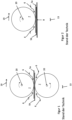
- FIG 1 an arrangement comprising two roller electrodes 7 according to the prior art is shown.
- figure 2 shows an arrangement according to the prior art, which compared to the arrangement according to figure 1 instead of the lower roller electrode 7, there is a flat counter-electrode 8, for example in the form of a table.
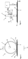
- figure 3 shows an arrangement analogous figure 2 but with a roller electrode arrangement 1.
- the roller electrode assembly 1 comprises a core 2 and a deformable electrically insulating coating 3, referred to as deformable coating 3 below.
- figure 4 shows a sectional side view figure 3 , Where further details are visible, in particular bearing 15 of the roller electrode assembly 1, a generator 4 and leads 9.
- the in figure 4 The view shown clearly shows that only one running surface of the core 2 is surrounded by the deformable coating 3 .
- figure 5 shows an arrangement analogous figure 1 but with two roller electrode arrangements 1.
- the Figures 6 to 8 show sectional side views of the illustration figure 5 with further details, which each differ with regard to their interconnection, in particular with regard to contacting with the generator 4 .
- the Figures 6 to 8 stands at least one of the Roller electrode assemblies 1 contactless via a device for contactless transmission 11 with the generator 4 in connection.
- the Figures 6 to 8 it can also be clearly seen that not only is a running surface of the core 2 surrounded by the deformable coating 3, but that it also encloses both side surfaces of the core 2.
- the devices for contactless transmission 11 are U-shaped electrodes that partially encompass the roller electrode arrangement 1 .
- roller electrode assembly 1 shown at the bottom of the figure which functions as a counter electrode, is grounded via the contactless transmission device 11 .
- An output of the generator 4 is also grounded.
- figure 8 is in addition to the arrangement after figure 7 a grounded support table 12 is provided.
- Devices comprising at least one roller electrode 7 are known from the prior art, which weld two workpieces 5a, 5b or two sections of a workpiece to one another.
- roller electrodes 7 In a device after figure 1 rotate this both roller electrodes 7 in opposite directions about the axes of rotation 20, as the arrows within Roller electrodes 7 indicate. Here, the roller electrodes 7 move relative to the workpieces 5a, 5b in the direction of an arrow 19.
- roller electrode 7 rotates and thus moves in the direction of the arrow 19 along the workpieces 5a, 5b to be welded, which are mounted on a flat counter-electrode 8, which usually acts as a table or as part of a table.
- a flat counter-electrode 8 which usually acts as a table or as part of a table.
- undesired plasma formation and plasma discharge occurs, for example, in an essentially wedge-shaped area indicated by arrows 6, since the field strength of the electric field emanating from or generated by the roller electrodes 7 is very strong in this area.
- a length 13 of the respective pressure zone ie that section within which the workpieces 5a, 5b are subjected to pressure, is indicated below the devices for the sake of clarity.
- the core 2 is the actual electrode, which is surrounded by the deformable coating 3.
- the core 2 i.e. the actual electrode, comes so close to the workpiece 5a or the section to be welded on top, approximately in the middle of the pressure zone, that a field strength sufficient for the welding is ensured.
- FIG 4 it is shown that the generator 4, which generates the high-frequency electrical alternating voltage, is connected to the core 2 via a supply line 9 and a collector 10, which is designed in the form of a sliding contact. Furthermore, the flat counter-electrode 8 is grounded and there is a coupling between the reference potential and the generator 4 via the principle of capacitive coupling between the flat counter-electrode 8 and the generator 4.
- a polarity of the voltage generated by the generator 4 is shown as a snapshot in numerous figures by "+HV” and "-HV".
- the polarity of the outputs of the generator 4 will of course vary with the frequency of the AC voltage being generated.
- the arrangements according to Figures 7 and 8 has the advantage that the roller electrode arrangements 1 shown below in the figures are connected to the generator 4 .
- the lower and the upper roller electrode assembly 1 are each subjected to the opposite polarity of the electrical AC voltage. As a result, the risk of plasma discharges can be further reduced since the potential difference between the electrodes or cores 2 is not different from the grounded zero potential.
- the grounded support table 12 again increases safety.
- a frame or the like can be considered instead of a table.
- such a table, such a frame or the like can be provided in order to support the workpieces 5a, 5b to be connected or to hold them during the welding.
- Such a table, such a frame or the like can thus be used solely for holding or supporting the workpieces 5a, 5b or sections to be connected, or also additionally as a counter-pressure element and optionally a counter-electrode
- the deformable coating 3 can either be provided only on the running surface of the core 2 or completely enclose the core 2 .
- the deformable coating 3 should preferably be arranged in such a way that it can effectively prevent sparks from plasma formation. It could also be considered to provide the running surface of the core 2 and directly adjacent sections of the side surfaces of the core 2, but not the entire side surfaces, with the deformable coating.
- the device 11 for contactless transmission does not necessarily have to be in the form of a U-shaped electrode; other devices of this type can also be used. These can work with the principle of capacitive coupling, but other options for contactless energy transmission can also be considered.
- the direction of movement 19 in the figures always relates to the movement of the roller electrode arrangements 1 relative to the workpieces 5a, 5b, es it is therefore a relative specification.
- the roller electrode arrangement 1 is preferably moved relative to the workpieces 5a, 5b, the reverse case is also conceivable. If the workpieces 5a, 5b to be welded are moved relative to one or two fixed roller electrode arrangements 1, then the workpieces 5a, 5b are moved in relation to the Figures 3 , 5 and 9 in the opposite direction of arrow 19.
- roller electrode assembly 34 2 core 35 3 coating 36 4 generator 37 5 workpiece 38 6 Arrow 39 7 roller electrode 40 8th Flat counter electrode 41 9 supply line 42 10 customer 43 11 Device for contactless transmission 44 12 Grounded support table 45 13 Length of the pressure zone 46 14 Wedge-shaped area 47 15 camp 48 16 49 17 50 18 51 19 direction of movement 52 20 axis of rotation 53 21 54 22 55 23 56 24 57 25 58 26 59 27 60 28 61 29 62 30 63 31 64 32 65 33 66
Landscapes
- Engineering & Computer Science (AREA)
- Mechanical Engineering (AREA)
- Physics & Mathematics (AREA)
- Thermal Sciences (AREA)
- Robotics (AREA)
- Lining Or Joining Of Plastics Or The Like (AREA)
Claims (12)
- Agencement d'électrodes à rouleaux (1) permettant de solliciter deux sections en plastique d'au moins une pièce (5a, 5b) avec un champ alternatif électrique à haute fréquence pour la liaison des sections par soudage par haute fréquence de plastique, comprenant un noyau (2), lequel est au moins partiellement constitué d'un matériau électriquement conducteur et est entouré d'un revêtement (3) déformable électriquement isolant, caractérisé en ce que l'agencement d'électrodes à rouleaux (1) est réalisé sous forme sphérique ou au moins sensiblement sphérique.
- Agencement d'électrodes à rouleaux (1) selon la revendication 1, caractérisé en ce que la fréquence du champ alternatif se situe dans une bande ISM.
- Dispositif permettant de solliciter une pièce (5a, 5b) avec un champ alternatif électrique à haute fréquence comprenant un générateur à haute fréquence ainsi qu'au moins un agencement d'électrodes à rouleaux (1) selon l'une des revendications 1 ou 2.
- Dispositif selon la revendication 3, caractérisé par un agencement de contre-électrodes (1), lequel est réalisé selon au moins l'une des revendications 1 ou 2.
- Dispositif selon l'une des revendications 3 ou 4, caractérisé en ce que l'agencement d'électrodes à rouleaux (1) ou au moins l'un des agencements d'électrodes à rouleaux (1) est conçu pour être entraîné afin de transporter la pièce (5a, 5b) à usiner.
- Dispositif selon au moins l'une des revendications 3 à 5, caractérisé par un appareil (11) permettant la transmission d'énergie sans contact à l'au moins un agencement d'électrodes à rouleaux (1).
- Dispositif selon au moins l'une des revendications 3, 5 ou 6, caractérisé par une table en tant qu'élément de contre-pression.
- Dispositif selon la revendication 7, caractérisé en ce que l'agencement d'électrodes à rouleaux (1) est guidé sur un système d'axes ou sur un robot à bras articulé.
- Dispositif selon au moins l'une des revendications 3 à 8,
caractérisé en ce que l'agencement d'électrodes à rouleaux (1) ou au moins l'un des agencements d'électrodes à rouleaux (1) est pourvu de disques métalliques mis à la terre latéralement, lesquels sont isolés électriquement de l'agencement d'électrodes à rouleaux (1). - Procédé permettant de solliciter deux sections en plastique d'au moins une pièce (5a, 5b) avec un champ alternatif électrique à haute fréquence pour la liaison des sections par soudage par haute fréquence de plastique, à l'aide d'un dispositif selon au moins l'une des revendications 3 à 9, caractérisé en ce que la pièce (5a, 5b) à usiner est sollicitée par une force au moyen d'un agencement d'électrodes à rouleaux (1) selon l'une des revendications 1 ou 2.
- Procédé selon la revendication 10, caractérisé en ce que la fréquence du champ alternatif se situe dans une bande ISM.
- Procédé selon l'une des revendications 10 ou 11, caractérisé en ce que la transmission de la haute fréquence électrique à l'agencement d'électrodes à rouleaux (1) ou au moins à l'un des agencements d'électrodes à rouleaux (1) s'effectue sans contact.
Applications Claiming Priority (2)
| Application Number | Priority Date | Filing Date | Title |
|---|---|---|---|
| DE102017110667.7A DE102017110667A1 (de) | 2017-05-17 | 2017-05-17 | Rollenelektrodenanordnung |
| PCT/EP2018/062348 WO2018210732A1 (fr) | 2017-05-17 | 2018-05-14 | Ensemble galet de soudage |
Publications (2)
| Publication Number | Publication Date |
|---|---|
| EP3625035A1 EP3625035A1 (fr) | 2020-03-25 |
| EP3625035B1 true EP3625035B1 (fr) | 2023-07-05 |
Family
ID=62245243
Family Applications (1)
| Application Number | Title | Priority Date | Filing Date |
|---|---|---|---|
| EP18727188.7A Active EP3625035B1 (fr) | 2017-05-17 | 2018-05-14 | Ensemble galet de soudage |
Country Status (4)
| Country | Link |
|---|---|
| EP (1) | EP3625035B1 (fr) |
| DE (1) | DE102017110667A1 (fr) |
| PL (1) | PL3625035T3 (fr) |
| WO (1) | WO2018210732A1 (fr) |
Families Citing this family (1)
| Publication number | Priority date | Publication date | Assignee | Title |
|---|---|---|---|---|
| DE102020102418B4 (de) | 2020-01-31 | 2025-03-27 | Deutsches Zentrum für Luft- und Raumfahrt e.V. | Effektor und Verfahren zum Plastifizieren von Kunststoffbauteilen |
Family Cites Families (6)
| Publication number | Priority date | Publication date | Assignee | Title |
|---|---|---|---|---|
| DE1154932B (de) | 1951-02-08 | 1963-09-26 | Sakuji Yamaguchi | Elektrodenvorrichtung fuer Hochfrequenz-Nahtschweissmaschinen insbesondere zum Verschweissen von Kunststoff-Folien |
| US3791906A (en) * | 1971-12-09 | 1974-02-12 | R Farkas | Method of using a compressible die member to form patterns on a plastic sheet including the use of a liquid plastisol and dielectric heating |
| WO1982003819A1 (fr) * | 1981-05-01 | 1982-11-11 | Maschf Erwin Kampf | Procede et appareil de liaison de feuilles de materiau |
| DE29906706U1 (de) * | 1999-04-15 | 1999-07-08 | NIMAK-Automatisierte-Schweißtechnik GmbH, 57537 Wissen | Schweißvorrichtung, insbesondere robotergeführte Rollennaht-Schweißzange |
| GB2367784B (en) * | 2000-10-10 | 2003-12-31 | Stanelco Fibre Optics Ltd | Welding polymeric sheets |
| JP2006130803A (ja) * | 2004-11-08 | 2006-05-25 | Kuinraito Denshi Seiko Kk | 高周波ミシン |
-
2017
- 2017-05-17 DE DE102017110667.7A patent/DE102017110667A1/de not_active Ceased
-
2018
- 2018-05-14 WO PCT/EP2018/062348 patent/WO2018210732A1/fr not_active Ceased
- 2018-05-14 PL PL18727188.7T patent/PL3625035T3/pl unknown
- 2018-05-14 EP EP18727188.7A patent/EP3625035B1/fr active Active
Also Published As
| Publication number | Publication date |
|---|---|
| WO2018210732A1 (fr) | 2018-11-22 |
| PL3625035T3 (pl) | 2023-11-13 |
| EP3625035A1 (fr) | 2020-03-25 |
| DE102017110667A1 (de) | 2018-11-22 |
Similar Documents
| Publication | Publication Date | Title |
|---|---|---|
| EP2605881B1 (fr) | Procédé et système de soudage de conducteurs électriques | |
| DE60027421T2 (de) | Vorrichtung zum verformen und heissiegeln von behältern | |
| EP3209433B1 (fr) | Élément d'usinage à surface structurée pour usinage par ultrasons | |
| AT410523B (de) | Andrückvorrichtung und verfahren zum schweissen von blechen | |
| EP3625035B1 (fr) | Ensemble galet de soudage | |
| EP3313645A1 (fr) | Dispositif de traitement, en particulier de soudage aux ultrasons, d'enveloppes d'emballage et utilisation du dispositif | |
| EP3807079B1 (fr) | Ensemble d'électrodes à galet, dispositif comprenant un ensemble d'électrodes à galet et procédé servant à soumettre deux sections en matière plastique à l'action d'un champ alternatif électrique à haute fréquence | |
| EP3469666B1 (fr) | Dispositif et procede de sertissage d'elements de liaison | |
| DE102017110669B3 (de) | Rollenelektrodenanordnung | |
| DE102019107539A1 (de) | Gestell für eine Bearbeitungsmaschine und Verfahren zum Bearbeiten eines Werkstücks mit derselben | |
| DE1236911B (de) | Sonotrode zum Kaltpress-Nahtschweissen metallischer Werkstuecke | |
| EP3615257A1 (fr) | Procédé de soudage de cadres en tôle et machine à souder à la molette en ligne continue | |
| DE19961351C1 (de) | Verfahren und Vorrichtung zum Verbinden der Enden von Metallbändern mittels Widerstandsschweißen | |
| DE10025159C2 (de) | Verfahren und Vorrichtung zum Verbinden der Enden zweier Metallbänder | |
| DE102017007964A1 (de) | WERKZEUG ZUM HF-VERSCHWEIßEN, ANLAGE ZUM VERSCHWEIßEN VON FOLIEN, ANLAGE ZUM HERSTELLEN EINES BEUTELS FÜR MEDIZINISCHE ZWECKE, VERFAHREN ZUM BETREIBEN EINER ANLAGE UND BEUTEL | |
| EP2151298B1 (fr) | Semelle de patin de ponçage | |
| EP4076821A1 (fr) | Dispositif de soudage par ultrasons et procédé de soudage par ultrasons doté d'un élément d'amortissement latéralement à côté de la face de contact | |
| EP2842080B1 (fr) | Fabrication d'un support de données portable | |
| DE202004020166U1 (de) | Schweißvorrichtung mit Schweißteil | |
| DE102020132523A1 (de) | Gegenelement für die Ultraschallbearbeitung | |
| DE2645091C3 (de) | Vorrichtung zum Widerstandsschweißen von Blechteilen zu Eckverbindungen | |
| DE102022117004A1 (de) | Verpackungsmaschinenvorrichtung und Verfahren mit einer derartigen Verpackungsmaschinenvorrichtung | |
| DE102021126679A1 (de) | Werkzeug für eine Ultraschallschweißvorrichtung | |
| EP4255720A1 (fr) | Élément d'usinage comprenant un élément structural | |
| DE1185320B (de) | Vorrichtung zur kontinuierlichen Erwaermung fortschreitend bewegter elektrisch nichtleitender Stoffe, insbesondere zum Zwecke der Verschweissung |
Legal Events
| Date | Code | Title | Description |
|---|---|---|---|
| STAA | Information on the status of an ep patent application or granted ep patent |
Free format text: STATUS: UNKNOWN |
|
| STAA | Information on the status of an ep patent application or granted ep patent |
Free format text: STATUS: THE INTERNATIONAL PUBLICATION HAS BEEN MADE |
|
| PUAI | Public reference made under article 153(3) epc to a published international application that has entered the european phase |
Free format text: ORIGINAL CODE: 0009012 |
|
| STAA | Information on the status of an ep patent application or granted ep patent |
Free format text: STATUS: REQUEST FOR EXAMINATION WAS MADE |
|
| 17P | Request for examination filed |
Effective date: 20191107 |
|
| AK | Designated contracting states |
Kind code of ref document: A1 Designated state(s): AL AT BE BG CH CY CZ DE DK EE ES FI FR GB GR HR HU IE IS IT LI LT LU LV MC MK MT NL NO PL PT RO RS SE SI SK SM TR |
|
| AX | Request for extension of the european patent |
Extension state: BA ME |
|
| DAV | Request for validation of the european patent (deleted) | ||
| DAX | Request for extension of the european patent (deleted) | ||
| STAA | Information on the status of an ep patent application or granted ep patent |
Free format text: STATUS: EXAMINATION IS IN PROGRESS |
|
| 17Q | First examination report despatched |
Effective date: 20210226 |
|
| GRAP | Despatch of communication of intention to grant a patent |
Free format text: ORIGINAL CODE: EPIDOSNIGR1 |
|
| STAA | Information on the status of an ep patent application or granted ep patent |
Free format text: STATUS: GRANT OF PATENT IS INTENDED |
|
| INTG | Intention to grant announced |
Effective date: 20221129 |
|
| GRAS | Grant fee paid |
Free format text: ORIGINAL CODE: EPIDOSNIGR3 |
|
| GRAA | (expected) grant |
Free format text: ORIGINAL CODE: 0009210 |
|
| STAA | Information on the status of an ep patent application or granted ep patent |
Free format text: STATUS: THE PATENT HAS BEEN GRANTED |
|
| AK | Designated contracting states |
Kind code of ref document: B1 Designated state(s): AL AT BE BG CH CY CZ DE DK EE ES FI FR GB GR HR HU IE IS IT LI LT LU LV MC MK MT NL NO PL PT RO RS SE SI SK SM TR |
|
| REG | Reference to a national code |
Ref country code: CH Ref legal event code: EP |
|
| REG | Reference to a national code |
Ref country code: AT Ref legal event code: REF Ref document number: 1584447 Country of ref document: AT Kind code of ref document: T Effective date: 20230715 |
|
| REG | Reference to a national code |
Ref country code: DE Ref legal event code: R096 Ref document number: 502018012621 Country of ref document: DE |
|
| REG | Reference to a national code |
Ref country code: IE Ref legal event code: FG4D Free format text: LANGUAGE OF EP DOCUMENT: GERMAN |
|
| REG | Reference to a national code |
Ref country code: SE Ref legal event code: TRGR |
|
| REG | Reference to a national code |
Ref country code: LT Ref legal event code: MG9D |
|
| REG | Reference to a national code |
Ref country code: NL Ref legal event code: MP Effective date: 20230705 |
|
| PG25 | Lapsed in a contracting state [announced via postgrant information from national office to epo] |
Ref country code: NL Free format text: LAPSE BECAUSE OF FAILURE TO SUBMIT A TRANSLATION OF THE DESCRIPTION OR TO PAY THE FEE WITHIN THE PRESCRIBED TIME-LIMIT Effective date: 20230705 |
|
| PG25 | Lapsed in a contracting state [announced via postgrant information from national office to epo] |
Ref country code: GR Free format text: LAPSE BECAUSE OF FAILURE TO SUBMIT A TRANSLATION OF THE DESCRIPTION OR TO PAY THE FEE WITHIN THE PRESCRIBED TIME-LIMIT Effective date: 20231006 |
|
| PG25 | Lapsed in a contracting state [announced via postgrant information from national office to epo] |
Ref country code: ES Free format text: LAPSE BECAUSE OF FAILURE TO SUBMIT A TRANSLATION OF THE DESCRIPTION OR TO PAY THE FEE WITHIN THE PRESCRIBED TIME-LIMIT Effective date: 20230705 |
|
| PG25 | Lapsed in a contracting state [announced via postgrant information from national office to epo] |
Ref country code: IS Free format text: LAPSE BECAUSE OF FAILURE TO SUBMIT A TRANSLATION OF THE DESCRIPTION OR TO PAY THE FEE WITHIN THE PRESCRIBED TIME-LIMIT Effective date: 20231105 |
|
| PG25 | Lapsed in a contracting state [announced via postgrant information from national office to epo] |
Ref country code: RS Free format text: LAPSE BECAUSE OF FAILURE TO SUBMIT A TRANSLATION OF THE DESCRIPTION OR TO PAY THE FEE WITHIN THE PRESCRIBED TIME-LIMIT Effective date: 20230705 Ref country code: PT Free format text: LAPSE BECAUSE OF FAILURE TO SUBMIT A TRANSLATION OF THE DESCRIPTION OR TO PAY THE FEE WITHIN THE PRESCRIBED TIME-LIMIT Effective date: 20231106 Ref country code: NO Free format text: LAPSE BECAUSE OF FAILURE TO SUBMIT A TRANSLATION OF THE DESCRIPTION OR TO PAY THE FEE WITHIN THE PRESCRIBED TIME-LIMIT Effective date: 20231005 Ref country code: LV Free format text: LAPSE BECAUSE OF FAILURE TO SUBMIT A TRANSLATION OF THE DESCRIPTION OR TO PAY THE FEE WITHIN THE PRESCRIBED TIME-LIMIT Effective date: 20230705 Ref country code: LT Free format text: LAPSE BECAUSE OF FAILURE TO SUBMIT A TRANSLATION OF THE DESCRIPTION OR TO PAY THE FEE WITHIN THE PRESCRIBED TIME-LIMIT Effective date: 20230705 Ref country code: IS Free format text: LAPSE BECAUSE OF FAILURE TO SUBMIT A TRANSLATION OF THE DESCRIPTION OR TO PAY THE FEE WITHIN THE PRESCRIBED TIME-LIMIT Effective date: 20231105 Ref country code: HR Free format text: LAPSE BECAUSE OF FAILURE TO SUBMIT A TRANSLATION OF THE DESCRIPTION OR TO PAY THE FEE WITHIN THE PRESCRIBED TIME-LIMIT Effective date: 20230705 Ref country code: GR Free format text: LAPSE BECAUSE OF FAILURE TO SUBMIT A TRANSLATION OF THE DESCRIPTION OR TO PAY THE FEE WITHIN THE PRESCRIBED TIME-LIMIT Effective date: 20231006 Ref country code: FI Free format text: LAPSE BECAUSE OF FAILURE TO SUBMIT A TRANSLATION OF THE DESCRIPTION OR TO PAY THE FEE WITHIN THE PRESCRIBED TIME-LIMIT Effective date: 20230705 Ref country code: ES Free format text: LAPSE BECAUSE OF FAILURE TO SUBMIT A TRANSLATION OF THE DESCRIPTION OR TO PAY THE FEE WITHIN THE PRESCRIBED TIME-LIMIT Effective date: 20230705 |
|
| REG | Reference to a national code |
Ref country code: DE Ref legal event code: R097 Ref document number: 502018012621 Country of ref document: DE |
|
| PG25 | Lapsed in a contracting state [announced via postgrant information from national office to epo] |
Ref country code: SM Free format text: LAPSE BECAUSE OF FAILURE TO SUBMIT A TRANSLATION OF THE DESCRIPTION OR TO PAY THE FEE WITHIN THE PRESCRIBED TIME-LIMIT Effective date: 20230705 Ref country code: RO Free format text: LAPSE BECAUSE OF FAILURE TO SUBMIT A TRANSLATION OF THE DESCRIPTION OR TO PAY THE FEE WITHIN THE PRESCRIBED TIME-LIMIT Effective date: 20230705 Ref country code: EE Free format text: LAPSE BECAUSE OF FAILURE TO SUBMIT A TRANSLATION OF THE DESCRIPTION OR TO PAY THE FEE WITHIN THE PRESCRIBED TIME-LIMIT Effective date: 20230705 Ref country code: DK Free format text: LAPSE BECAUSE OF FAILURE TO SUBMIT A TRANSLATION OF THE DESCRIPTION OR TO PAY THE FEE WITHIN THE PRESCRIBED TIME-LIMIT Effective date: 20230705 Ref country code: CZ Free format text: LAPSE BECAUSE OF FAILURE TO SUBMIT A TRANSLATION OF THE DESCRIPTION OR TO PAY THE FEE WITHIN THE PRESCRIBED TIME-LIMIT Effective date: 20230705 Ref country code: SK Free format text: LAPSE BECAUSE OF FAILURE TO SUBMIT A TRANSLATION OF THE DESCRIPTION OR TO PAY THE FEE WITHIN THE PRESCRIBED TIME-LIMIT Effective date: 20230705 |
|
| PLBE | No opposition filed within time limit |
Free format text: ORIGINAL CODE: 0009261 |
|
| STAA | Information on the status of an ep patent application or granted ep patent |
Free format text: STATUS: NO OPPOSITION FILED WITHIN TIME LIMIT |
|
| 26N | No opposition filed |
Effective date: 20240408 |
|
| PGFP | Annual fee paid to national office [announced via postgrant information from national office to epo] |
Ref country code: GB Payment date: 20240521 Year of fee payment: 7 |
|
| PG25 | Lapsed in a contracting state [announced via postgrant information from national office to epo] |
Ref country code: SI Free format text: LAPSE BECAUSE OF FAILURE TO SUBMIT A TRANSLATION OF THE DESCRIPTION OR TO PAY THE FEE WITHIN THE PRESCRIBED TIME-LIMIT Effective date: 20230705 |
|
| PG25 | Lapsed in a contracting state [announced via postgrant information from national office to epo] |
Ref country code: BG Free format text: LAPSE BECAUSE OF FAILURE TO SUBMIT A TRANSLATION OF THE DESCRIPTION OR TO PAY THE FEE WITHIN THE PRESCRIBED TIME-LIMIT Effective date: 20230705 |
|
| PG25 | Lapsed in a contracting state [announced via postgrant information from national office to epo] |
Ref country code: BG Free format text: LAPSE BECAUSE OF FAILURE TO SUBMIT A TRANSLATION OF THE DESCRIPTION OR TO PAY THE FEE WITHIN THE PRESCRIBED TIME-LIMIT Effective date: 20230705 |
|
| REG | Reference to a national code |
Ref country code: CH Ref legal event code: PL |
|
| PG25 | Lapsed in a contracting state [announced via postgrant information from national office to epo] |
Ref country code: MC Free format text: LAPSE BECAUSE OF FAILURE TO SUBMIT A TRANSLATION OF THE DESCRIPTION OR TO PAY THE FEE WITHIN THE PRESCRIBED TIME-LIMIT Effective date: 20230705 |
|
| PG25 | Lapsed in a contracting state [announced via postgrant information from national office to epo] |
Ref country code: LU Free format text: LAPSE BECAUSE OF NON-PAYMENT OF DUE FEES Effective date: 20240514 |
|
| PG25 | Lapsed in a contracting state [announced via postgrant information from national office to epo] |
Ref country code: MC Free format text: LAPSE BECAUSE OF FAILURE TO SUBMIT A TRANSLATION OF THE DESCRIPTION OR TO PAY THE FEE WITHIN THE PRESCRIBED TIME-LIMIT Effective date: 20230705 Ref country code: LU Free format text: LAPSE BECAUSE OF NON-PAYMENT OF DUE FEES Effective date: 20240514 Ref country code: CH Free format text: LAPSE BECAUSE OF NON-PAYMENT OF DUE FEES Effective date: 20240531 |
|
| REG | Reference to a national code |
Ref country code: BE Ref legal event code: MM Effective date: 20240531 |
|
| PG25 | Lapsed in a contracting state [announced via postgrant information from national office to epo] |
Ref country code: IE Free format text: LAPSE BECAUSE OF NON-PAYMENT OF DUE FEES Effective date: 20240514 |
|
| PG25 | Lapsed in a contracting state [announced via postgrant information from national office to epo] |
Ref country code: BE Free format text: LAPSE BECAUSE OF NON-PAYMENT OF DUE FEES Effective date: 20240531 |
|
| PGFP | Annual fee paid to national office [announced via postgrant information from national office to epo] |
Ref country code: PL Payment date: 20250529 Year of fee payment: 8 |
|
| PGFP | Annual fee paid to national office [announced via postgrant information from national office to epo] |
Ref country code: IT Payment date: 20250522 Year of fee payment: 8 |
|
| REG | Reference to a national code |
Ref country code: AT Ref legal event code: MM01 Ref document number: 1584447 Country of ref document: AT Kind code of ref document: T Effective date: 20240514 |
|
| PGFP | Annual fee paid to national office [announced via postgrant information from national office to epo] |
Ref country code: FR Payment date: 20250523 Year of fee payment: 8 |
|
| PG25 | Lapsed in a contracting state [announced via postgrant information from national office to epo] |
Ref country code: AT Free format text: LAPSE BECAUSE OF NON-PAYMENT OF DUE FEES Effective date: 20240514 |
|
| PGFP | Annual fee paid to national office [announced via postgrant information from national office to epo] |
Ref country code: SE Payment date: 20250520 Year of fee payment: 8 |
|
| PG25 | Lapsed in a contracting state [announced via postgrant information from national office to epo] |
Ref country code: CY Free format text: LAPSE BECAUSE OF FAILURE TO SUBMIT A TRANSLATION OF THE DESCRIPTION OR TO PAY THE FEE WITHIN THE PRESCRIBED TIME-LIMIT; INVALID AB INITIO Effective date: 20180514 |
|
| PG25 | Lapsed in a contracting state [announced via postgrant information from national office to epo] |
Ref country code: HU Free format text: LAPSE BECAUSE OF FAILURE TO SUBMIT A TRANSLATION OF THE DESCRIPTION OR TO PAY THE FEE WITHIN THE PRESCRIBED TIME-LIMIT; INVALID AB INITIO Effective date: 20180514 |
|
| PGFP | Annual fee paid to national office [announced via postgrant information from national office to epo] |
Ref country code: DE Payment date: 20250728 Year of fee payment: 8 |
|
| GBPC | Gb: european patent ceased through non-payment of renewal fee |
Effective date: 20250514 |