EP3625035B1 - Rollenelektrodenanordnung - Google Patents
Rollenelektrodenanordnung Download PDFInfo
- Publication number
- EP3625035B1 EP3625035B1 EP18727188.7A EP18727188A EP3625035B1 EP 3625035 B1 EP3625035 B1 EP 3625035B1 EP 18727188 A EP18727188 A EP 18727188A EP 3625035 B1 EP3625035 B1 EP 3625035B1
- Authority
- EP
- European Patent Office
- Prior art keywords
- roller electrode
- electrode arrangement
- frequency
- roller
- workpiece
- Prior art date
- Legal status (The legal status is an assumption and is not a legal conclusion. Google has not performed a legal analysis and makes no representation as to the accuracy of the status listed.)
- Active
Links
Images


Classifications
-
- B—PERFORMING OPERATIONS; TRANSPORTING
- B29—WORKING OF PLASTICS; WORKING OF SUBSTANCES IN A PLASTIC STATE IN GENERAL
- B29C—SHAPING OR JOINING OF PLASTICS; SHAPING OF MATERIAL IN A PLASTIC STATE, NOT OTHERWISE PROVIDED FOR; AFTER-TREATMENT OF THE SHAPED PRODUCTS, e.g. REPAIRING
- B29C65/00—Joining or sealing of preformed parts, e.g. welding of plastics materials; Apparatus therefor
- B29C65/02—Joining or sealing of preformed parts, e.g. welding of plastics materials; Apparatus therefor by heating, with or without pressure
- B29C65/04—Dielectric heating, e.g. high-frequency welding, i.e. radio frequency welding of plastic materials having dielectric properties, e.g. PVC
-
- B—PERFORMING OPERATIONS; TRANSPORTING
- B29—WORKING OF PLASTICS; WORKING OF SUBSTANCES IN A PLASTIC STATE IN GENERAL
- B29C—SHAPING OR JOINING OF PLASTICS; SHAPING OF MATERIAL IN A PLASTIC STATE, NOT OTHERWISE PROVIDED FOR; AFTER-TREATMENT OF THE SHAPED PRODUCTS, e.g. REPAIRING
- B29C65/00—Joining or sealing of preformed parts, e.g. welding of plastics materials; Apparatus therefor
- B29C65/48—Joining or sealing of preformed parts, e.g. welding of plastics materials; Apparatus therefor using adhesives, i.e. using supplementary joining material; solvent bonding
- B29C65/4805—Joining or sealing of preformed parts, e.g. welding of plastics materials; Apparatus therefor using adhesives, i.e. using supplementary joining material; solvent bonding characterised by the type of adhesives
- B29C65/481—Non-reactive adhesives, e.g. physically hardening adhesives
- B29C65/4815—Hot melt adhesives, e.g. thermoplastic adhesives
-
- B—PERFORMING OPERATIONS; TRANSPORTING
- B29—WORKING OF PLASTICS; WORKING OF SUBSTANCES IN A PLASTIC STATE IN GENERAL
- B29C—SHAPING OR JOINING OF PLASTICS; SHAPING OF MATERIAL IN A PLASTIC STATE, NOT OTHERWISE PROVIDED FOR; AFTER-TREATMENT OF THE SHAPED PRODUCTS, e.g. REPAIRING
- B29C65/00—Joining or sealing of preformed parts, e.g. welding of plastics materials; Apparatus therefor
- B29C65/78—Means for handling the parts to be joined, e.g. for making containers or hollow articles, e.g. means for handling sheets, plates, web-like materials, tubular articles, hollow articles or elements to be joined therewith; Means for discharging the joined articles from the joining apparatus
- B29C65/7858—Means for handling the parts to be joined, e.g. for making containers or hollow articles, e.g. means for handling sheets, plates, web-like materials, tubular articles, hollow articles or elements to be joined therewith; Means for discharging the joined articles from the joining apparatus characterised by the feeding movement of the parts to be joined
- B29C65/7888—Means for handling of moving sheets or webs
- B29C65/7894—Means for handling of moving sheets or webs of continuously moving sheets or webs
-
- B—PERFORMING OPERATIONS; TRANSPORTING
- B29—WORKING OF PLASTICS; WORKING OF SUBSTANCES IN A PLASTIC STATE IN GENERAL
- B29C—SHAPING OR JOINING OF PLASTICS; SHAPING OF MATERIAL IN A PLASTIC STATE, NOT OTHERWISE PROVIDED FOR; AFTER-TREATMENT OF THE SHAPED PRODUCTS, e.g. REPAIRING
- B29C66/00—General aspects of processes or apparatus for joining preformed parts
- B29C66/006—Preventing damaging, e.g. of the parts to be joined
-
- B—PERFORMING OPERATIONS; TRANSPORTING
- B29—WORKING OF PLASTICS; WORKING OF SUBSTANCES IN A PLASTIC STATE IN GENERAL
- B29C—SHAPING OR JOINING OF PLASTICS; SHAPING OF MATERIAL IN A PLASTIC STATE, NOT OTHERWISE PROVIDED FOR; AFTER-TREATMENT OF THE SHAPED PRODUCTS, e.g. REPAIRING
- B29C66/00—General aspects of processes or apparatus for joining preformed parts
- B29C66/01—General aspects dealing with the joint area or with the area to be joined
- B29C66/05—Particular design of joint configurations
- B29C66/10—Particular design of joint configurations particular design of the joint cross-sections
- B29C66/11—Joint cross-sections comprising a single joint-segment, i.e. one of the parts to be joined comprising a single joint-segment in the joint cross-section
- B29C66/112—Single lapped joints
- B29C66/1122—Single lap to lap joints, i.e. overlap joints
-
- B—PERFORMING OPERATIONS; TRANSPORTING
- B29—WORKING OF PLASTICS; WORKING OF SUBSTANCES IN A PLASTIC STATE IN GENERAL
- B29C—SHAPING OR JOINING OF PLASTICS; SHAPING OF MATERIAL IN A PLASTIC STATE, NOT OTHERWISE PROVIDED FOR; AFTER-TREATMENT OF THE SHAPED PRODUCTS, e.g. REPAIRING
- B29C66/00—General aspects of processes or apparatus for joining preformed parts
- B29C66/40—General aspects of joining substantially flat articles, e.g. plates, sheets or web-like materials; Making flat seams in tubular or hollow articles; Joining single elements to substantially flat surfaces
- B29C66/41—Joining substantially flat articles ; Making flat seams in tubular or hollow articles
- B29C66/43—Joining a relatively small portion of the surface of said articles
-
- B—PERFORMING OPERATIONS; TRANSPORTING
- B29—WORKING OF PLASTICS; WORKING OF SUBSTANCES IN A PLASTIC STATE IN GENERAL
- B29C—SHAPING OR JOINING OF PLASTICS; SHAPING OF MATERIAL IN A PLASTIC STATE, NOT OTHERWISE PROVIDED FOR; AFTER-TREATMENT OF THE SHAPED PRODUCTS, e.g. REPAIRING
- B29C66/00—General aspects of processes or apparatus for joining preformed parts
- B29C66/70—General aspects of processes or apparatus for joining preformed parts characterised by the composition, physical properties or the structure of the material of the parts to be joined; Joining with non-plastics material
- B29C66/71—General aspects of processes or apparatus for joining preformed parts characterised by the composition, physical properties or the structure of the material of the parts to be joined; Joining with non-plastics material characterised by the composition of the plastics material of the parts to be joined
- B29C66/712—General aspects of processes or apparatus for joining preformed parts characterised by the composition, physical properties or the structure of the material of the parts to be joined; Joining with non-plastics material characterised by the composition of the plastics material of the parts to be joined the composition of one of the parts to be joined being different from the composition of the other part
-
- B—PERFORMING OPERATIONS; TRANSPORTING
- B29—WORKING OF PLASTICS; WORKING OF SUBSTANCES IN A PLASTIC STATE IN GENERAL
- B29C—SHAPING OR JOINING OF PLASTICS; SHAPING OF MATERIAL IN A PLASTIC STATE, NOT OTHERWISE PROVIDED FOR; AFTER-TREATMENT OF THE SHAPED PRODUCTS, e.g. REPAIRING
- B29C66/00—General aspects of processes or apparatus for joining preformed parts
- B29C66/70—General aspects of processes or apparatus for joining preformed parts characterised by the composition, physical properties or the structure of the material of the parts to be joined; Joining with non-plastics material
- B29C66/73—General aspects of processes or apparatus for joining preformed parts characterised by the composition, physical properties or the structure of the material of the parts to be joined; Joining with non-plastics material characterised by the intensive physical properties of the material of the parts to be joined, by the optical properties of the material of the parts to be joined, by the extensive physical properties of the parts to be joined, by the state of the material of the parts to be joined or by the material of the parts to be joined being a thermoplastic or a thermoset
- B29C66/739—General aspects of processes or apparatus for joining preformed parts characterised by the composition, physical properties or the structure of the material of the parts to be joined; Joining with non-plastics material characterised by the intensive physical properties of the material of the parts to be joined, by the optical properties of the material of the parts to be joined, by the extensive physical properties of the parts to be joined, by the state of the material of the parts to be joined or by the material of the parts to be joined being a thermoplastic or a thermoset characterised by the material of the parts to be joined being a thermoplastic or a thermoset
- B29C66/7392—General aspects of processes or apparatus for joining preformed parts characterised by the composition, physical properties or the structure of the material of the parts to be joined; Joining with non-plastics material characterised by the intensive physical properties of the material of the parts to be joined, by the optical properties of the material of the parts to be joined, by the extensive physical properties of the parts to be joined, by the state of the material of the parts to be joined or by the material of the parts to be joined being a thermoplastic or a thermoset characterised by the material of the parts to be joined being a thermoplastic or a thermoset characterised by the material of at least one of the parts being a thermoplastic
- B29C66/73921—General aspects of processes or apparatus for joining preformed parts characterised by the composition, physical properties or the structure of the material of the parts to be joined; Joining with non-plastics material characterised by the intensive physical properties of the material of the parts to be joined, by the optical properties of the material of the parts to be joined, by the extensive physical properties of the parts to be joined, by the state of the material of the parts to be joined or by the material of the parts to be joined being a thermoplastic or a thermoset characterised by the material of the parts to be joined being a thermoplastic or a thermoset characterised by the material of at least one of the parts being a thermoplastic characterised by the materials of both parts being thermoplastics
-
- B—PERFORMING OPERATIONS; TRANSPORTING
- B29—WORKING OF PLASTICS; WORKING OF SUBSTANCES IN A PLASTIC STATE IN GENERAL
- B29C—SHAPING OR JOINING OF PLASTICS; SHAPING OF MATERIAL IN A PLASTIC STATE, NOT OTHERWISE PROVIDED FOR; AFTER-TREATMENT OF THE SHAPED PRODUCTS, e.g. REPAIRING
- B29C66/00—General aspects of processes or apparatus for joining preformed parts
- B29C66/80—General aspects of machine operations or constructions and parts thereof
- B29C66/81—General aspects of the pressing elements, i.e. the elements applying pressure on the parts to be joined in the area to be joined, e.g. the welding jaws or clamps
- B29C66/814—General aspects of the pressing elements, i.e. the elements applying pressure on the parts to be joined in the area to be joined, e.g. the welding jaws or clamps characterised by the design of the pressing elements, e.g. of the welding jaws or clamps
- B29C66/8145—General aspects of the pressing elements, i.e. the elements applying pressure on the parts to be joined in the area to be joined, e.g. the welding jaws or clamps characterised by the design of the pressing elements, e.g. of the welding jaws or clamps characterised by the constructional aspects of the pressing elements, e.g. of the welding jaws or clamps
- B29C66/81457—General aspects of the pressing elements, i.e. the elements applying pressure on the parts to be joined in the area to be joined, e.g. the welding jaws or clamps characterised by the design of the pressing elements, e.g. of the welding jaws or clamps characterised by the constructional aspects of the pressing elements, e.g. of the welding jaws or clamps comprising a block or layer of deformable material, e.g. sponge, foam, rubber
-
- B—PERFORMING OPERATIONS; TRANSPORTING
- B29—WORKING OF PLASTICS; WORKING OF SUBSTANCES IN A PLASTIC STATE IN GENERAL
- B29C—SHAPING OR JOINING OF PLASTICS; SHAPING OF MATERIAL IN A PLASTIC STATE, NOT OTHERWISE PROVIDED FOR; AFTER-TREATMENT OF THE SHAPED PRODUCTS, e.g. REPAIRING
- B29C66/00—General aspects of processes or apparatus for joining preformed parts
- B29C66/80—General aspects of machine operations or constructions and parts thereof
- B29C66/81—General aspects of the pressing elements, i.e. the elements applying pressure on the parts to be joined in the area to be joined, e.g. the welding jaws or clamps
- B29C66/818—General aspects of the pressing elements, i.e. the elements applying pressure on the parts to be joined in the area to be joined, e.g. the welding jaws or clamps characterised by the cooling constructional aspects, or by the thermal or electrical insulating or conducting constructional aspects of the welding jaws or of the clamps ; comprising means for compensating for the thermal expansion of the welding jaws or of the clamps
- B29C66/8187—General aspects of the pressing elements, i.e. the elements applying pressure on the parts to be joined in the area to be joined, e.g. the welding jaws or clamps characterised by the cooling constructional aspects, or by the thermal or electrical insulating or conducting constructional aspects of the welding jaws or of the clamps ; comprising means for compensating for the thermal expansion of the welding jaws or of the clamps characterised by the electrical insulating constructional aspects
- B29C66/81871—General aspects of the pressing elements, i.e. the elements applying pressure on the parts to be joined in the area to be joined, e.g. the welding jaws or clamps characterised by the cooling constructional aspects, or by the thermal or electrical insulating or conducting constructional aspects of the welding jaws or of the clamps ; comprising means for compensating for the thermal expansion of the welding jaws or of the clamps characterised by the electrical insulating constructional aspects of the welding jaws
-
- B—PERFORMING OPERATIONS; TRANSPORTING
- B29—WORKING OF PLASTICS; WORKING OF SUBSTANCES IN A PLASTIC STATE IN GENERAL
- B29C—SHAPING OR JOINING OF PLASTICS; SHAPING OF MATERIAL IN A PLASTIC STATE, NOT OTHERWISE PROVIDED FOR; AFTER-TREATMENT OF THE SHAPED PRODUCTS, e.g. REPAIRING
- B29C66/00—General aspects of processes or apparatus for joining preformed parts
- B29C66/80—General aspects of machine operations or constructions and parts thereof
- B29C66/81—General aspects of the pressing elements, i.e. the elements applying pressure on the parts to be joined in the area to be joined, e.g. the welding jaws or clamps
- B29C66/818—General aspects of the pressing elements, i.e. the elements applying pressure on the parts to be joined in the area to be joined, e.g. the welding jaws or clamps characterised by the cooling constructional aspects, or by the thermal or electrical insulating or conducting constructional aspects of the welding jaws or of the clamps ; comprising means for compensating for the thermal expansion of the welding jaws or of the clamps
- B29C66/8188—General aspects of the pressing elements, i.e. the elements applying pressure on the parts to be joined in the area to be joined, e.g. the welding jaws or clamps characterised by the cooling constructional aspects, or by the thermal or electrical insulating or conducting constructional aspects of the welding jaws or of the clamps ; comprising means for compensating for the thermal expansion of the welding jaws or of the clamps characterised by the electrical conducting constructional aspects
- B29C66/81881—General aspects of the pressing elements, i.e. the elements applying pressure on the parts to be joined in the area to be joined, e.g. the welding jaws or clamps characterised by the cooling constructional aspects, or by the thermal or electrical insulating or conducting constructional aspects of the welding jaws or of the clamps ; comprising means for compensating for the thermal expansion of the welding jaws or of the clamps characterised by the electrical conducting constructional aspects of the welding jaws
-
- B—PERFORMING OPERATIONS; TRANSPORTING
- B29—WORKING OF PLASTICS; WORKING OF SUBSTANCES IN A PLASTIC STATE IN GENERAL
- B29C—SHAPING OR JOINING OF PLASTICS; SHAPING OF MATERIAL IN A PLASTIC STATE, NOT OTHERWISE PROVIDED FOR; AFTER-TREATMENT OF THE SHAPED PRODUCTS, e.g. REPAIRING
- B29C66/00—General aspects of processes or apparatus for joining preformed parts
- B29C66/80—General aspects of machine operations or constructions and parts thereof
- B29C66/83—General aspects of machine operations or constructions and parts thereof characterised by the movement of the joining or pressing tools
- B29C66/834—General aspects of machine operations or constructions and parts thereof characterised by the movement of the joining or pressing tools moving with the parts to be joined
- B29C66/8341—Roller, cylinder or drum types; Band or belt types; Ball types
- B29C66/83411—Roller, cylinder or drum types
- B29C66/83413—Roller, cylinder or drum types cooperating rollers, cylinders or drums
-
- B—PERFORMING OPERATIONS; TRANSPORTING
- B29—WORKING OF PLASTICS; WORKING OF SUBSTANCES IN A PLASTIC STATE IN GENERAL
- B29C—SHAPING OR JOINING OF PLASTICS; SHAPING OF MATERIAL IN A PLASTIC STATE, NOT OTHERWISE PROVIDED FOR; AFTER-TREATMENT OF THE SHAPED PRODUCTS, e.g. REPAIRING
- B29C66/00—General aspects of processes or apparatus for joining preformed parts
- B29C66/80—General aspects of machine operations or constructions and parts thereof
- B29C66/83—General aspects of machine operations or constructions and parts thereof characterised by the movement of the joining or pressing tools
- B29C66/834—General aspects of machine operations or constructions and parts thereof characterised by the movement of the joining or pressing tools moving with the parts to be joined
- B29C66/8341—Roller, cylinder or drum types; Band or belt types; Ball types
- B29C66/83411—Roller, cylinder or drum types
- B29C66/83415—Roller, cylinder or drum types the contact angle between said rollers, cylinders or drums and said parts to be joined being a non-zero angle
-
- B—PERFORMING OPERATIONS; TRANSPORTING
- B29—WORKING OF PLASTICS; WORKING OF SUBSTANCES IN A PLASTIC STATE IN GENERAL
- B29C—SHAPING OR JOINING OF PLASTICS; SHAPING OF MATERIAL IN A PLASTIC STATE, NOT OTHERWISE PROVIDED FOR; AFTER-TREATMENT OF THE SHAPED PRODUCTS, e.g. REPAIRING
- B29C66/00—General aspects of processes or apparatus for joining preformed parts
- B29C66/80—General aspects of machine operations or constructions and parts thereof
- B29C66/83—General aspects of machine operations or constructions and parts thereof characterised by the movement of the joining or pressing tools
- B29C66/836—Moving relative to and tangentially to the parts to be joined, e.g. transversely to the displacement of the parts to be joined, e.g. using a X-Y table
- B29C66/8362—Rollers, cylinders or drums moving relative to and tangentially to the parts to be joined
-
- B—PERFORMING OPERATIONS; TRANSPORTING
- B29—WORKING OF PLASTICS; WORKING OF SUBSTANCES IN A PLASTIC STATE IN GENERAL
- B29C—SHAPING OR JOINING OF PLASTICS; SHAPING OF MATERIAL IN A PLASTIC STATE, NOT OTHERWISE PROVIDED FOR; AFTER-TREATMENT OF THE SHAPED PRODUCTS, e.g. REPAIRING
- B29C66/00—General aspects of processes or apparatus for joining preformed parts
- B29C66/80—General aspects of machine operations or constructions and parts thereof
- B29C66/84—Specific machine types or machines suitable for specific applications
- B29C66/863—Robotised, e.g. mounted on a robot arm
-
- B—PERFORMING OPERATIONS; TRANSPORTING
- B29—WORKING OF PLASTICS; WORKING OF SUBSTANCES IN A PLASTIC STATE IN GENERAL
- B29C—SHAPING OR JOINING OF PLASTICS; SHAPING OF MATERIAL IN A PLASTIC STATE, NOT OTHERWISE PROVIDED FOR; AFTER-TREATMENT OF THE SHAPED PRODUCTS, e.g. REPAIRING
- B29C66/00—General aspects of processes or apparatus for joining preformed parts
- B29C66/70—General aspects of processes or apparatus for joining preformed parts characterised by the composition, physical properties or the structure of the material of the parts to be joined; Joining with non-plastics material
- B29C66/71—General aspects of processes or apparatus for joining preformed parts characterised by the composition, physical properties or the structure of the material of the parts to be joined; Joining with non-plastics material characterised by the composition of the plastics material of the parts to be joined
-
- B—PERFORMING OPERATIONS; TRANSPORTING
- B29—WORKING OF PLASTICS; WORKING OF SUBSTANCES IN A PLASTIC STATE IN GENERAL
- B29C—SHAPING OR JOINING OF PLASTICS; SHAPING OF MATERIAL IN A PLASTIC STATE, NOT OTHERWISE PROVIDED FOR; AFTER-TREATMENT OF THE SHAPED PRODUCTS, e.g. REPAIRING
- B29C66/00—General aspects of processes or apparatus for joining preformed parts
- B29C66/80—General aspects of machine operations or constructions and parts thereof
- B29C66/83—General aspects of machine operations or constructions and parts thereof characterised by the movement of the joining or pressing tools
- B29C66/834—General aspects of machine operations or constructions and parts thereof characterised by the movement of the joining or pressing tools moving with the parts to be joined
- B29C66/8341—Roller, cylinder or drum types; Band or belt types; Ball types
- B29C66/83441—Ball types
Definitions
- the invention relates to a roller electrode arrangement according to the preamble of claim 1 and a device comprising such a roller electrode arrangement and a method for applying a high-frequency electrical alternating field to a workpiece.
- roller electrodes for high-frequency welding of plastics.
- high-frequency welding of plastics is also used for the non-detachable connection of two workpieces or sections, here two plastic workpieces or sections, which are subjected to heat and pressure.
- plastic high-frequency welding two sections of one or more plastic workpieces to be joined are usually heated locally at the same time by applying an alternating electric field, causing them to melt, and are pressed together using pressure, causing them to be permanently connected to one another.
- the heating is caused by the interaction between the alternating electric field and the polar components of the polymer or plastic. This leads to local heating because the dipoles in the plastic try to align themselves in the electric field, even though they are firmly embedded in the polymer structure of the plastic.
- plastics such as thermoplastic polyurethane (TPU), polyvinyl chloride (PVC), ethylene propylene diene rubber (EPDM) or polymethyl methacrylate (PMMA) can be considered.
- TPU thermoplastic polyurethane
- PVC polyvinyl chloride
- EPDM ethylene propylene diene rubber
- PMMA polymethyl methacrylate
- Machines for high-frequency welding (HF welding) of plastics generally include a generator or high-frequency generator, welding electrodes and a press, it being possible for the aforementioned components to be combined at least in part.
- the generator is used to generate a high-frequency electrical AC voltage, for example at 27.12 MHz, and usually several kilovolts.
- the press is used to press the welding electrodes onto the workpiece to be processed or onto the sections to be welded, and the electrodes are used for local heating of the plastic by generating the alternating field.
- sparks can form at a contact point between a supply line emanating from the generator and the electrode, which is often designed as a sliding contact in the case of electrodes that rotate during operation.
- this spark formation was counteracted by selecting high-quality and reliable sliding contacts.
- plasma discharge sparking can occur.
- This plasma discharge occurs in areas between the electrodes where there is a sufficiently high electric field strength.
- electrodes in the form of a roller such areas are present on both sides of a pressure zone between the electrode and the workpiece to be machined and are essentially wedge-shaped.
- DE 1 154 932 A which also addresses the problem of sparking.
- sparking occurs due to poor point contacts.
- the DE 1 154 932 A propose to equip one of the coil-shaped electrodes with an external helical wire spring which is flexible and can be partially depressed by the opposite coil-shaped electrode.
- an external helical wire spring which is flexible and can be partially depressed by the opposite coil-shaped electrode.
- a surface contact takes the place of the point contact, which reduces the risk of sparking.
- JP 2006 130 803 A1 relates to a roller electrode assembly for high-frequency welding.
- the object of the present invention is to overcome the disadvantages of the prior art.
- a roller electrode arrangement or a device comprising such a roller electrode arrangement is to be provided which is as flexible as possible with regard to the workpiece(s) to be welded and at the same time provides the best possible pressing or the best possible pressing zone and efficiently reduces the risk of sparks.
- a roller electrode arrangement according to the invention for applying a high-frequency electrical alternating field to a workpiece comprises a core which consists at least partially of electrically conductive material and is surrounded by a deformable electrically insulating coating, hereinafter referred to simply as deformable coating.
- the deformable coating deforms, which leads to an enlargement of the pressure zone.
- a major advantage is that the deformable coating is electrically insulating.
- the risk of plasma formation and correspondingly also of plasma discharge is at least greatly reduced.
- the deformable coating can consist of a plastic. It should be ensured that the plastic is not or not significantly interacts with the alternating electric field or is largely inert to it. Appropriate elastomers or silicones can be considered here, for example.
- a thickness of the deformable coating can be between 0.1 mm and 5 mm, for example. The range between 0.2 mm and 4 mm can also be considered, as well as the range between 0.3 mm and 3 mm and the range between 0.4 mm and 2.5 mm and preferably the range between 0.5 mm and 2mm.
- a roller electrode arrangement is considered to be a device or arrangement comprising an electrode with a circular cross section, which can move over a workpiece in a rolling manner. If a fixed roller electrode arrangement is to be used, it can alternatively be considered to move the workpiece accordingly relative to the electrode, while the latter is indeed mounted in a fixed position, but at the same time carries out a rotary movement.
- the roller electrode arrangement is spherical or at least substantially spherical.
- a particular advantage of an at least essentially spherical roller electrode arrangement is that plastic sections to be connected with a complex weld seam geometry can also be reliably welded.
- numerous roller electrodes known from the prior art can only reliably weld sections that require a straight weld seam.
- the workpiece to be machined or the sections to be connected or welded are weldable plastics with a correspondingly high dielectric loss factor.
- the high-frequency electrical alternating field is preferably an alternating field with a frequency of 27.12 MHz. However, other frequencies, in particular industrial frequencies or ISM bands, can also be considered.
- ISM bands can be considered: 6.765 MHz to 6.795 MHz; 13.553MHz to 13.567MHz; 26.957MHz to 27.283MHz; 40.66MHz to 40.70MHz; 433.05MHz to 434.79MHz or 902MHz to 928MHz.
- the central frequencies of the ISM bands can be thought of in particular, for example 13.56 MHz, 40.68 MHz or 433.92 MHz are listed here.
- the present invention should also include a device for applying a high-frequency electrical alternating field to a workpiece, comprising a high-frequency generator and at least one roller electrode arrangement as described above. This device will be described below.
- the device always includes a second electrode or counter-electrode or counter-electrode arrangement, in which case, for example, a flat electrode can also be considered. It is thus possible to form a part of a table, on which the sections to be welded lie, in the form of a flat electrode. It can also be considered to let a flat electrode into a table or the like.
- the counter-electrode arrangement is preferably designed as described above for the roller electrode arrangement.
- Such an arrangement is much easier to handle than an arrangement in which part of the table is designed as an electrode, for example because the table and the associated electrode, which can be embedded in the table, for example, are usually very large.
- Both electrode arrangements preferably also act as a pressure element and are subjected to force in the direction of the workpiece using appropriate means, so that separate pressure elements can be dispensed with.
- the at least one roller electrode arrangement is preferably set up to be driven in order to transport the workpiece to be machined. There are therefore no separate feed or transport necessary. If the device comprises two roller electrode arrangements, on the one hand only one can be driven, with the second preferably rotating passively as a result of the movement of the workpiece brought about by the first roller electrode arrangement. On the other hand, it can also be considered that both roller electrode arrangements actively rotate or are driven, which should preferably take place synchronously.
- the roller electrode arrangement or the roller electrode arrangements can each be mounted in an air bearing or in a roller bearing. Numerous types of mounting are conceivable which, for example, act on the roller electrode arrangement via a central axis of the latter.
- a bearing via roller bearings or, in general, a bearing similar to known older generation computer mice or similar to the bearing of known trackballs in input devices is used in particular.
- the use of air bearings can be considered for the at least essentially spherical roller electrode arrangements.
- the device preferably includes a device for the contactless transmission of energy or an electrical high-frequency to the at least one roller electrode arrangement.
- a device for the contactless transmission of energy or an electrical high-frequency to the at least one roller electrode arrangement This results in the advantage that, for example in contrast to sliding contacts and the like, the risk of sparking at a contact point between the feed line and the electrode is significantly reduced.
- the contactless transmission can take place, for example, by capacitive coupling, with energy being transmitted wirelessly by means of an electric field.
- Corresponding devices are sufficiently known from the prior art.
- a second roller electrode arrangement can be assigned to a roller electrode arrangement, which fulfills both the task of the counter electrode and the task of a counter pressure element.
- the device can include a table as a counter-pressure element.
- a flat counter-electrode can be embedded or incorporated into the table in the manner already described.
- the device can comprise a table not only as an alternative to the counter-electrode but also as a complement.
- This can be used, for example, as a support table for the workpieces or sections to be welded.
- the support table can, for example, comprise a recess through which the counter-electrode contacts the workpieces to be welded.
- a table serving as a counter-pressure element with an embedded counter-electrode can represent an essentially planar counter-pressure element.
- the table can have three-dimensional contours, which can be adapted, for example, to the sections to be connected.
- a device can also be envisaged which comprises an axis system or an articulated-arm robot on which the roller electrode arrangement(s) is/are guided. With such an arrangement, the welding can be carried out in a highly automated manner and very quickly. Corresponding axis systems and articulated arm robots are sufficiently known from the prior art.
- roller electrode arrangement or at least one of the roller electrode arrangements with grounded metal discs on the side, which are electrically insulated from the roller electrode arrangement. This is preferably used for isolation and can prevent accidents at work and unwanted sparking.
- the present invention also relates to a method for applying a high-frequency electrical alternating field to a workpiece by means of a device as described above, wherein the workpiece to be machined is also subjected to a force with a roller electrode arrangement as also described above.
- the device is in particular a device for high-frequency welding of plastics. However, it can also be considered to use the alternating electric field for other purposes, for example for gluing two workpieces or sections.
- thermoplastic polyurethane TPU
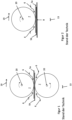
- FIG 1 an arrangement comprising two roller electrodes 7 according to the prior art is shown.
- figure 2 shows an arrangement according to the prior art, which compared to the arrangement according to figure 1 instead of the lower roller electrode 7, there is a flat counter-electrode 8, for example in the form of a table.
- figure 3 shows an arrangement analogous figure 2 but with a roller electrode arrangement 1.
- the roller electrode assembly 1 comprises a core 2 and a deformable electrically insulating coating 3, referred to as deformable coating 3 below.
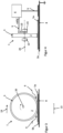
- figure 4 shows a sectional side view figure 3 , Where further details are visible, in particular bearing 15 of the roller electrode assembly 1, a generator 4 and leads 9.
- the in figure 4 The view shown clearly shows that only one running surface of the core 2 is surrounded by the deformable coating 3 .
- figure 5 shows an arrangement analogous figure 1 but with two roller electrode arrangements 1.
- the Figures 6 to 8 show sectional side views of the illustration figure 5 with further details, which each differ with regard to their interconnection, in particular with regard to contacting with the generator 4 .
- the Figures 6 to 8 stands at least one of the Roller electrode assemblies 1 contactless via a device for contactless transmission 11 with the generator 4 in connection.
- the Figures 6 to 8 it can also be clearly seen that not only is a running surface of the core 2 surrounded by the deformable coating 3, but that it also encloses both side surfaces of the core 2.
- the devices for contactless transmission 11 are U-shaped electrodes that partially encompass the roller electrode arrangement 1 .
- roller electrode assembly 1 shown at the bottom of the figure which functions as a counter electrode, is grounded via the contactless transmission device 11 .
- An output of the generator 4 is also grounded.
- figure 8 is in addition to the arrangement after figure 7 a grounded support table 12 is provided.
- Devices comprising at least one roller electrode 7 are known from the prior art, which weld two workpieces 5a, 5b or two sections of a workpiece to one another.
- roller electrodes 7 In a device after figure 1 rotate this both roller electrodes 7 in opposite directions about the axes of rotation 20, as the arrows within Roller electrodes 7 indicate. Here, the roller electrodes 7 move relative to the workpieces 5a, 5b in the direction of an arrow 19.
- roller electrode 7 rotates and thus moves in the direction of the arrow 19 along the workpieces 5a, 5b to be welded, which are mounted on a flat counter-electrode 8, which usually acts as a table or as part of a table.
- a flat counter-electrode 8 which usually acts as a table or as part of a table.
- undesired plasma formation and plasma discharge occurs, for example, in an essentially wedge-shaped area indicated by arrows 6, since the field strength of the electric field emanating from or generated by the roller electrodes 7 is very strong in this area.
- a length 13 of the respective pressure zone ie that section within which the workpieces 5a, 5b are subjected to pressure, is indicated below the devices for the sake of clarity.
- the core 2 is the actual electrode, which is surrounded by the deformable coating 3.
- the core 2 i.e. the actual electrode, comes so close to the workpiece 5a or the section to be welded on top, approximately in the middle of the pressure zone, that a field strength sufficient for the welding is ensured.
- FIG 4 it is shown that the generator 4, which generates the high-frequency electrical alternating voltage, is connected to the core 2 via a supply line 9 and a collector 10, which is designed in the form of a sliding contact. Furthermore, the flat counter-electrode 8 is grounded and there is a coupling between the reference potential and the generator 4 via the principle of capacitive coupling between the flat counter-electrode 8 and the generator 4.
- a polarity of the voltage generated by the generator 4 is shown as a snapshot in numerous figures by "+HV” and "-HV".
- the polarity of the outputs of the generator 4 will of course vary with the frequency of the AC voltage being generated.
- the arrangements according to Figures 7 and 8 has the advantage that the roller electrode arrangements 1 shown below in the figures are connected to the generator 4 .
- the lower and the upper roller electrode assembly 1 are each subjected to the opposite polarity of the electrical AC voltage. As a result, the risk of plasma discharges can be further reduced since the potential difference between the electrodes or cores 2 is not different from the grounded zero potential.
- the grounded support table 12 again increases safety.
- a frame or the like can be considered instead of a table.
- such a table, such a frame or the like can be provided in order to support the workpieces 5a, 5b to be connected or to hold them during the welding.
- Such a table, such a frame or the like can thus be used solely for holding or supporting the workpieces 5a, 5b or sections to be connected, or also additionally as a counter-pressure element and optionally a counter-electrode
- the deformable coating 3 can either be provided only on the running surface of the core 2 or completely enclose the core 2 .
- the deformable coating 3 should preferably be arranged in such a way that it can effectively prevent sparks from plasma formation. It could also be considered to provide the running surface of the core 2 and directly adjacent sections of the side surfaces of the core 2, but not the entire side surfaces, with the deformable coating.
- the device 11 for contactless transmission does not necessarily have to be in the form of a U-shaped electrode; other devices of this type can also be used. These can work with the principle of capacitive coupling, but other options for contactless energy transmission can also be considered.
- the direction of movement 19 in the figures always relates to the movement of the roller electrode arrangements 1 relative to the workpieces 5a, 5b, es it is therefore a relative specification.
- the roller electrode arrangement 1 is preferably moved relative to the workpieces 5a, 5b, the reverse case is also conceivable. If the workpieces 5a, 5b to be welded are moved relative to one or two fixed roller electrode arrangements 1, then the workpieces 5a, 5b are moved in relation to the Figures 3 , 5 and 9 in the opposite direction of arrow 19.
- roller electrode assembly 34 2 core 35 3 coating 36 4 generator 37 5 workpiece 38 6 Arrow 39 7 roller electrode 40 8th Flat counter electrode 41 9 supply line 42 10 customer 43 11 Device for contactless transmission 44 12 Grounded support table 45 13 Length of the pressure zone 46 14 Wedge-shaped area 47 15 camp 48 16 49 17 50 18 51 19 direction of movement 52 20 axis of rotation 53 21 54 22 55 23 56 24 57 25 58 26 59 27 60 28 61 29 62 30 63 31 64 32 65 33 66
Landscapes
- Engineering & Computer Science (AREA)
- Mechanical Engineering (AREA)
- Physics & Mathematics (AREA)
- Thermal Sciences (AREA)
- Robotics (AREA)
- Lining Or Joining Of Plastics Or The Like (AREA)
Description
- Die Erfindung betrifft eine Rollenelektrodenanordnung nach dem Oberbegriff des Anspruchs 1 sowie eine Vorrichtung umfassend eine solche Rollenelektrodenanordnung und ein Verfahren zur Beaufschlagung eines Werkstücks mit einem hochfrequenten elektrischen Wechselfeld.
- Es ist bekannt, Rollenelektroden zum Hochfrequenzschweißen von Kunststoffen einzusetzen.
- Wie andere Schweißverfahren dient auch das Hochfrequenzschweißen von Kunststoffen dem unlösbaren Verbinden zweier Werkstücke oder Abschnitte, hier zweier Kunststoff-Werkstücke bzw. -Abschnitte, welche mit Wärme und Druck beaufschlagt werden.
- Es ist bekannt, Planen für Fahrzeuge, Sonnenschutz-Planen, Werbeflächen, Kleidung, Verpackungen, aufblasbare Produkte wie Schlauchboote und Hüpfburgen sowie Wasserbetten und flexible Flüssigkeitstanks und vieles mehr durch Kunststoff-Hochfrequenzschweißen herzustellen.
- Beim Kunststoff-Hochfrequenzschweißen werden zwei zu verbindende Abschnitte eines oder mehrerer Kunststoff-Werkstücke durch Anlegen eines elektrischen Wechselfelds üblicherweise zugleich lokal erhitzt, wodurch sie aufgeschmolzen werden, und unter Anwendung von Druck miteinander verpresst, wodurch sie dauerhaft miteinander verbunden werden.
- Die Erwärmung entsteht durch Wechselwirkung zwischen dem elektrischen Wechselfeld und polaren Bestandteilen des Polymers bzw. Kunststoffes. Hierbei kommt es zu einer lokalen Erwärmung, weil im Kunststoff vorhandene Dipole sich im elektrischen Feld auszurichten versuchen, obwohl sie fest in das Polymergefüge des Kunststoffes eingebunden sind.
- Ob ein Kunststoff also mittels Hochfrequenzschweißen bearbeitbar ist, hängt von seinem molekularen Aufbau, genauer von der Anwesenheit von Dipolen ab. Aus diesem Grund lassen sich nur bestimmte Kunststoffe mittels Hochfrequenzschweißen bearbeiten. Maßgeblich für die Verschweißbarkeit ist der dielektrische Verlustfaktor des Kunststoffes, der ein Maß für den Energieverlust darstellt, den der betreffende Kunststoff als Isolierstoff im elektrischen Feld bewirkt. Beispielsweise kommen Kunststoffe wie thermoplastisches Polyurethan (TPU), Polyvinylchlorid (PVC), Ethylen-Propylen-Dien-Kautschuk (EPDM) oder Polymethylmethacrylat (PMMA) in Betracht.
- Aufgrund der hohen Leistung, mit welcher Hochfrequenz-Kunststoff-Schweißanlagen betrieben werden, diese liegt teilweise im zweistelligen Kilowattbereich, sind bestimmte einzuhaltende Frequenzen gesetzlich vorgegeben. Am häufigsten wird ein elektrisches Wechselfeld mit einer Frequenz von 27.12 MHz verwendet, da es sich um ein sogenanntes "ISM-Band" handelt, welches beispielsweise von Hochfrequenzgeräten in der Industrie frei benutzt werden kann.
- Maschinen zum Hochfrequenzschweißen (HF-Schweißen) von Kunststoffen umfassen in der Regel einen Generator bzw. Hochfrequenzgenerator, Schweißelektroden und eine Presse, wobei die vorgenannten Bauteile zumindest teilweise zusammengefasst sein können. Der Generator dient der Erzeugung einer hochfrequenten elektrischen Wechselspannung, beispielsweise mit 27.12 MHz, und üblicherweise mehreren Kilovolt. Die Presse dient dazu, die Schweißelektroden auf das zu bearbeitende Werkstück bzw. die zu verschweißenden Abschnitte zu pressen und die Elektroden dienen der lokalen Erhitzung des Kunststoffes, indem sie das Wechselfeld erzeugen.
- Vorrichtungen und Verfahren zum Hochfrequenz-Kunststoffschweißen sind in zahlreichen Ausführungen bekannt. Wird die Anlage kontinuierliche betrieben, so ist es beispielsweise bekannt, die zu verschweißenden Kunststoff-Abschnitte zwischen zwei rollenförmigen Elektroden hindurch zu bewegen. Ein hierbei anzutreffendes Problem stellt die Funkenbildung an mehreren Orten dar.
- Einerseits kann Funkenbildung an einer Kontaktstelle zwischen einer vom Generator ausgehenden Zuleitung und der Elektrode, welche bei sich im Betrieb drehenden Elektroden oftmals als Schleifkontakt ausgebildet ist. Im Stand der Technik wurde dieser Funkenbildung durch die Auswahl hochwertiger und zuverlässiger Schleifkontakte entgegengetreten.
- Andererseits kann Funkenbildung durch Plasmaentladung auftreten. Zu dieser Plasmaentladung kommt es in Bereichen zwischen den Elektroden, an denen eine ausreichend hohe elektrische Feldstärke vorliegt. Im Fall von rollenförmigen Elektroden sind derartige Bereiche beidseits einer Andruckzone zwischen Elektrode und zu bearbeitendem Werkstück vorhanden und im Wesentlichen keilförmig.
- Aus dem Stand der Technik ist beispielsweise die
DE 1 154 932 A bekannt, welche auch das Problem der Funkenbildung adressiert. Gemäß derDE 1 154 932 A tritt die Funkenbildung jedoch auf Grund mangelhafter Punktkontakte auf. Dementsprechend schlägt dieDE 1 154 932 A vor, eine der rollenförmigen Elektroden mit einer außenliegenden schraubenförmigen Drahtfeder auszustatten, die flexibel ist und von der gegenüberliegenden rollenförmigen Elektrode teilweise eingedrückt werden kann. Somit tritt ein flächiger Kontakt an die Stelle des Punktkontaktes, was das Risiko des Funkenschlags verringert. Allerdings sind noch immer Funkenschläge durch Plasmaentladungen in demjenigen Bereich zu befürchten, welcher direkt an die Kontaktstelle beider Elektroden angrenzt. Dieses Problem wird von derDE 1 154 932 A nicht gelöst. - Ein weiteres Problem bekannter Vorrichtungen und Verfahren zum Hochfrequenz-Kunststoffschweißen ist in einer unzureichenden Druckbeaufschlagung zu verschweißender Kunststoffabschnitte zu sehen.
- Um eine Andruckzone zu verlängern, wurde im Stand der Technik vorgeschlagen, einer rollenförmigen Elektrode, welche zugleich als Presse dient, eine konkave Gegenelektrode zuzuordnen, welche komplementär zur rollenförmigen Elektrode geformt ist und somit die Andruckzone verlängert. Dies macht die Vorrichtung jedoch sehr unflexibel hinsichtlich der Ausgestaltung verschiedener zu bearbeitender Werkstoffe. Beispielsweise kann eine Schweißnahtgeometrie, welche Kurven aufweist, mit einer konkaven Gegenelektrode nicht bearbeitet werden.
- Ferner ist im Stand der Technik an zusätzliche Andruckrollen gedacht, welche jedoch ebenfalls die Komplexität der Anlage zu Lasten der Flexibilität hinsichtlich etwaiger zu bearbeitender Werkstoffe erhöhen. Auch hier ergibt sich nämlich stets das Problem, dass nur geradlinige Schweißnähte ohne Kurven erzeugt werden können.
- Im Stand der Technik sind ausserdem die
DE 299 06 706 U1 betreffend eine robotergeführte Rollennaht-Schweißzange sowie dieGB 2 367 784 A - Aus dem Stand der Technik ist ferner die
JP 2006 130 803 A1 - Ferner ist die
US 3 791 906 A1 bekannt, welche ein Verfahren für die HitzeBehandlung von Kunststoffen offenbart. - Weiterhin ist die
DE 972 333 B bekannt, welche eine Vorrichtung zum Hochfrequenzschweissen offenbart. - Die Aufgabe der vorliegenden Erfindung ist es, die Nachteile aus dem Stand der Technik zu überwinden. Insbesondere soll eine Rollenelektrodenanordnung bzw. eine Vorrichtung umfassend eine solche Rollenelektrodenanordnung bereitgestellt werden, welche hinsichtlich des oder der zu verschweißenden Werkstücke(s) möglichst flexibel ist und zugleich ein möglichst optimales Andrücken bzw. eine möglichst optimale Andruckzone bereitstellt und die Gefahr von Funkenschlag effizient verringert.
- Zur Lösung der Aufgabe führen die Gegenstände der unabhängigen Ansprüche.
- Vorteilhafte Ausgestaltungen sind in den Unteransprüchen beschrieben.
- Eine erfindungsgemäße Rollenelektrodenanordnung zur Beaufschlagung eines Werkstücks mit einem hochfrequenten elektrischen Wechselfeld umfasst einen Kern, welcher zumindest teilweise aus elektrisch leitendem Material besteht und von einer deformierbaren elektrisch isolierenden Beschichtung, nachfolgend lediglich als deformierbare Beschichtung bezeichnet, umgeben ist.
- Wird die Rollenelektrodenanordnung beispielsweise auf zwei miteinander zu verschweißende Kunststoffabschnitte gedrückt, um diese zu verschweißen, so verformt sich die deformierbare Beschichtung, was zu einer Vergrößerung der Andruckzone führt. Indem der für das Verschweißen nötige Druck im Vergleich zu unbeschichteten Rollenelektrodenanordnungen und im Vergleich zu Rollenelektrodenanordnungen mit einer starren Beschichtung über eine vergrößerte Zone hinweg auf die zu verbindenden Kunststoffabschnitte ausgeübt wird, werden diese länger mit Druck beaufschlagt, was wiederum die Qualität der Verbindung verbessert. Beispielsweise kann daher beim kontinuierlichen HF-Kunststoffschweißen die Geschwindigkeit gegenüber bekannten Verfahren erhöht werden. Weiterhin kann auf separate Andruckelemente wie Andruckrollen und dergleichen verzichtet werden.
- Ein wesentlicher Vorteil ist jedoch, dass die deformierbare Beschichtung elektrisch isolierend ist. Hierdurch wird in unmittelbarer Nachbarschaft zur Andruckzone, innerhalb der die Feldstärke des elektrischen Wechselfelds sehr stark ist, die Gefahr von Plasma-Bildung und entsprechend auch von PlasmaEntladung zumindest stark verringert.
- Die deformierbare Beschichtung kann aus einem Kunststoff bestehen. Hierbei sollte darauf geachtet werden, dass der Kunststoff nicht oder nicht wesentlich mit dem elektrische Wechselfeld in Wechselwirkung tritt bzw. diesem gegenüber weitgehend inert ist. Hierbei kann beispielsweise an entsprechende Elastomere oder Silikone gedacht sein. Eine Dicke der deformierbaren Beschichtung kann beispielsweise zwischen 0,1 mm und 5 mm liegen. Es kann auch an den Bereich zwischen 0.2 mm und 4 mm gedacht sein, ferner an den Bereich zwischen 0,3 mm und 3 mm sowie an den Bereich zwischen 0,4 mm und 2,5 mm sowie bevorzugt an den Bereich zwischen 0,5 mm und 2 mm.
- Hierbei wird im Rahmen der vorliegenden Erfindung unter Rollenelektrodenanordnung eine Einrichtung bzw. Anordnung umfassend Elektrode mit kreisförmigem Querschnitt angesehen, welche sich rollend über ein Werkstück hinweg bewegen kann. Falls eine feststehende Rollenelektrodenanordnung verwendet werden soll, kann alternativ daran gedacht sein, das Werkstück entsprechend relativ zur Elektrode zu bewegen, während diese zwar ortsfest gelagert ist, aber gleichzeitig eine Drehbewegung ausführt.
- Die Rollenelektrodenanordnung ist kugelförmig oder zumindest im Wesentlichen kugelförmig ausgebildet.
- Ein besonderer Vorteil einer zumindest im Wesentlichen kugelförmigen Rollenelektrodenanordnung liegt darin, dass auch zu verbindende Kunststoff-Abschnitte mit komplexer Schweißnaht-Geometrie zuverlässig verschweißt werden können. Zahlreiche aus dem Stand der Technik bekannte Rollenelektroden können demgegenüber nur solche Abschnitte zuverlässig verschweißen, die eine geradlinige Schweißnaht erfordern.
- Bei dem zu bearbeitenden Werkstück oder bei den zu verbindenden bzw. verschweißenden Abschnitten handelt es sich um verschweißbare Kunststoffe mit entsprechend hohem dielektrischen Verlustfaktor. Bei dem hochfrequenten elektrischen Wechselfeld handelt es sich vorzugsweise um ein Wechselfeld mit einer Frequenz von 27.12 MHz. Es kann aber auch an andere Frequenzen, insbesondere an Industriefrequenzen bzw. ISM-Bänder gedacht sein.
- Insbesondere kann an folgende ISM-Bänder gedacht sein: 6,765 MHz bis 6,795 MHz; 13,553 MHz bis 13,567 MHz; 26,957 MHz bis 27,283 MHz; 40,66 MHz bis 40,70 MHz; 433,05 MHz bis 434,79 MHz oder 902 MHz bis 928 MHz. Ganz besonders kann an die Zentralfrequenzen der ISM-Bänder gedacht sein, beispielhaft seien hier 13.56 MHz, 40,68 MHz oder 433,92 MHz aufgeführt.
- Von der vorliegenden Erfindung soll auch eine Vorrichtung zur Beaufschlagung eines Werkstücks mit einem hochfrequenten elektrischen Wechselfeld umfassend einen Hochfrequenzgenerator sowie zumindest eine Rollenelektrodenanordnung wie vorstehend beschrieben umfasst sein. Diese Vorrichtung wird nachfolgend beschrieben.
- Derartige Generatoren sind aus dem Stand der Technik hinreichend bekannt. Die Vorrichtung umfasst stets eine zweite Elektrode bzw. Gegenelektrode oder Gegenelektrodenanordnung, wobei hier beispielsweise auch an eine flächige Elektrode gedacht sein kann. So ist es möglich, einen Teil eines Tisches, auf welchem die zu verschweißenden Abschnitte liegen, in Form einer flächigen Elektrode auszubilden. Es kann auch daran gedacht sein, eine flächige Elektrode in einen Tisch oder dergleichen einzulassen.
- Bevorzugt ist die Gegenelektrodenanordnung jedoch so ausgebildet, wie vorstehend für die Rollenelektrodenanordnung beschrieben. Eine solche Anordnung ist deutlich einfacher handhabbar als eine Anordnung, bei welcher ein Teil des Tisches als Elektrode ausgebildet ist, beispielsweise, weil der Tisch und die zugehörige Elektrode, welche beispielsweise im Tisch eingelassen sein kann, üblicherweise sehr gross ausfallen.
- Vorzugsweise wirken beide Elektrodenanordnungen auch als Andruckelement und werden mit entsprechenden Mitteln in Richtung auf das Werkstück zu mit Kraft beaufschlagt, so dass auf separate Andruckelemente verzichtet werden kann.
- Vorzugsweise ist die zumindest eine Rollenelektrodenanordnung eingerichtet, um angetrieben zu werden, um das zu bearbeitende Werkstück zu transportieren. Es sind somit keine separaten Vorschub- oder Transportmittel nötig. Umfasst die Vorrichtung zwei Rollenelektrodenanordnungen, so kann einerseits nur eine angetrieben sein, wobei die zweite sich vorzugsweise durch die von der ersten Rollenelektrodenanordnung bewirkte Bewegung des Werkstücks passiv dreht. Andererseits kann auch daran gedacht sein, dass beide Rollenelektrodenanordnungen sich aktiv drehen bzw. angetrieben werden, was vorzugsweise synchron erfolgen sollte.
- Die Rollenelektrodenanordnung bzw. die Rollenelektrodenanordnungen können jeweils in einem Luftlager oder in einem Rollenlager gelagert sein. Es sind zahlreiche Arten der Lagerung denkbar, welche beispielsweise über eine zentrale Achse der Rollenelektrodenanordnung an dieser angreifen. Für die im Wesentlichen kugelförmigen Rollenelektrodenanordnungen kommt insbesondere eine Lagerung über Rollenlager bzw. im Allgemeinen eine Lagerung ähnlich bekannter Computer-Mäuse älterer Generation oder ähnlich der Lagerung bekannter Trackballs in Eingabegeräten zum Einsatz. Ferner kann bei den zumindest im Wesentlichen kugelförmigen Rollenelektrodenanordnungen an die Verwendung von Luftlagern gedacht sein.
- Vorzugsweise umfasst die Vorrichtung eine Einrichtung zur kontaktlosen Übertragung von Energie bzw. einer elektrischen Hochfrequenz auf die zumindest eine Rollenelektrodenanordnung. Daraus ergibt sich der Vorteil, dass, beispielsweise im Gegensatz zu Schleifkontakten und dergleichen, die Gefahr eine Funkenschlags an einer Kontaktstelle zwischen Zuleitung und Elektrode deutlich sinkt. Die kontaktlose Übertragung kann beispielsweise durch kapazitive Kopplung erfolgen, wobei Energie mittels eines elektrischen Feldes drahtlos übertragen wird. Entsprechende Vorrichtungen sind aus dem Stand der Technik hinreichend bekannt.
- Wie bereits ausgeführt kann einer Rollenelektrodenanordnung eine zweite Rollenelektrodenanordnung zugeordnet sein, welche sowohl die Aufgabe der Gegenelektrode als auch die Aufgabe eines Gegendruckelements erfüllt.
- Alternativ kann die Vorrichtung einen Tisch als Gegendruckelement umfassen In den Tisch kann auf bereits beschriebene Weise eine flächige Gegenelektrode eingelassen bzw. eingearbeitet sein.
- Ferner kann die Vorrichtung nicht nur alternativ zur Gegenelektrode sondern auch komplementär einen Tisch umfassen. Dieser kann beispielsweise als Auflagentisch für die zu verschweißenden Werkstücke bzw. Abschnitte dienen. Der Auflagentisch kann beispielsweise eine Ausnehmung umfassen, durch welche die Gegenelektrode die zu verschweißenden Werkstücke kontaktiert.
- Ein als Gegendruckelement dienender Tisch mit eingelassener Gegenelektrode kann hierbei ein im Wesentlichen planes Gegendruckelement darstellen. Alternativ kann der Tisch jedoch dreidimensionale Konturen aufweisen, welche beispielsweise an die zu verbindenden Abschnitte angepasst sein können.
- Es kann auch an eine Vorrichtung gedacht sein, welche ein Achssystem oder einen Knickarmroboter umfasst, an welchem die Rollenelektrodenanordnung(en) geführt ist bzw. geführt sind. Durch eine solche Anordnung kann das Verschweißen hochautomatisiert und sehr schnell durchgeführt werden. Entsprechende Achssysteme und Knickarmroboter sind aus dem Stand der Technik hinreichend bekannt.
- In sämtlichen der vorstehend beschriebenen Ausführungsbeispiele kann daran gedacht sein, die Rollenelektrodenanordnung bzw. zumindest eine der Rollenelektrodenanordnungen seitlich mit geerdeten Metallscheiben zu versehen, welche gegenüber der Rollenelektrodenanordnung elektrisch isoliert sind. Dies dient vorzugsweise der Isolation und kann Arbeitsunfälle sowie unerwünschten Funkenschlag verhindern.
- Die vorliegende Erfindung betrifft ferner ein Verfahren zur Beaufschlagung eines Werkstücks mit einem hochfrequenten elektrischen Wechselfeld mittels einer Vorrichtung wie vorstehend beschrieben, wobei das zu bearbeitende Werkstück mit einer Rollenelektrodenanordnung wie ebenfalls vorstehend beschrieben auch mit einer Kraft beaufschlagt wird.
- Hinsichtlich dieses Verfahrens kann daran gedacht sein, die Übertragung der elektrischen Hochfrequenz auf die Rollenelektrodenanordnung bzw. zumindest eine der Rollenelektrodenanordnungen kontaktlos erfolgen zu lassen, beispielsweise durch das Prinzip der kapazitiven Kopplung.
- Bei der Vorrichtung handelt es sich insbesondere um eine Vorrichtung zum Hochfrequenzschweißen von Kunststoffen. Es kann aber auch daran gedacht sein, das elektrische Wechselfeld für andere Zwecke zu nutzen, beispielsweise zum Verleimen zweier Werkstücke oder Abschnitte.
- Im Allgemeinen kann stets daran gedacht sein, zwei Abschnitte desselben Werkstücks oder zwei Abschnitte verschiedener Werkstücke miteinander zu verbinden, insbesondere zu verschweißen.
- Werden zwei Werkstücke miteinander verbunden, so ist vorzugsweise daran gedacht, dass diese aus demselben Material gefertigt sind. Es kann aber auch daran gedacht sein, dass beide aus unterschiedlichen Materialien gefertigt sind. Hierbei kann es sich als vorteilhaft erweisen, beispielsweise thermoplastisches Polyurethan (TPU) als Verbinder bzw. Schweißzusatz zu verwenden.
- Weitere Vorteile, Merkmale und Einzelheiten der Erfindung ergeben sich aus der nachfolgenden Beschreibung bevorzugter Ausführungsbeispiele sowie anhand der Zeichnungen; diese zeigen in:
-
Figur 1 eine Anordnung umfassend zwei Rollenelektroden 7 gemäß dem Stand der Technik, -
Figur 2 eine Anordnung umfassend eine Rollenelektrode 7 und ein flächige Gegenelektrode 8 gemäß dem Stand der Technik, -
Figur 3 eine Anordnung umfassend eine Rollenelektrodenanordnung 1 gemäß einem Ausführungsbeispiel der vorliegenden Erfindung, -
Figur 4 eine geschnittene Seitenansicht nachFigur 3 mit weiteren Details, -
Figur 5 eine Anordnung umfassend zwei Rollenelektrodenanordnungen 1 gemäß einem weiteren Ausführungsbeispiel der vorliegenden Erfindung, -
Figur 6 eine geschnittene Seitenansicht nachFigur 5 mit weiteren Details in einer ersten Variante, -
Figur 7 eine geschnittene Seitenansicht nachFigur 5 mit weiteren Details in einer zweiten Variante und -
Figur 8 eine geschnittene Seitenansicht nachFigur 5 mit weiteren Details in einer dritten Variante. - Da die Ausführungsbeispiele gemäss den
Figuren 3 bis 8 keine zumindest im wesentlichen kugelförmigen Rollenelektrodenanordnungen zeigen, sind sie nicht Teil der Erfindung. Die nicht erfindungsgemässen Ausführungsbeispiele nach denFiguren 3 bis 8 erleichtern jedoch das Verständnis der vorliegenden Erfindung. - In
Figur 1 ist eine Anordnung umfassend zwei Rollenelektroden 7 gemäß dem Stand der Technik dargestellt. -
Figur 2 zeigt eine Anordnung gemäß dem Stand der Technik, welche im Vergleich zur Anordnung nachFigur 1 anstatt der unteren Rollenelektrode 7 eine flächige Gegenelektrode 8, beispielsweise in Form eines Tisches, umfasst. -
Figur 3 zeigt eine Anordnung analogFigur 2 jedoch mit einer Rollenelektrodenanordnung 1. - Die Rollenelektrodenanordnung 1 umfasst einen Kern 2 und eine deformierbare elektrisch isolierende Beschichtung 3, nachfolgend als deformierbare Beschichtung 3 bezeichnet.
-
Figur 4 zeigt eine geschnittene Seitenansicht nachFigur 3 , wobei weitere Details sichtbar sind, insbesondere Lager 15 der Rollenelektrodenanordnung 1, ein Generator 4 und Zuleitungen 9. Der inFigur 4 gezeigten Ansicht ist deutlich entnehmbar, dass lediglich eine Lauffläche des Kerns 2 von der deformierbaren Beschichtung 3 umgeben ist. -
Figur 5 zeigt eine Anordnung analogFigur 1 jedoch mit zwei Rollenelektrodenanordnungen 1. - Die
Figuren 6 bis 8 zeigen geschnittene Seitenansichten der Darstellung nachFigur 5 mit weiteren Details, welche sich jeweils hinsichtlich ihrer Verschaltung, insbesondere hinsichtlich Kontaktierung mit dem Generator 4, unterscheiden. In denFiguren 6 bis 8 steht jeweils zumindest eine der Rollenelektrodenanordnungen 1 kontaktlos über eine Einrichtung zur kontaktlosen Übertragung 11 mit dem Generator 4 in Verbindung. DenFiguren 6 bis 8 ist ferner deutlich entnehmbar, dass nicht nur eine Lauffläche des Kerns 2 von der deformierbaren Beschichtung 3 umgeben ist, sondern diese auch beide Seitenflächen des Kerns 2 umfängt. - Bei den Einrichtungen zur kontaktlosen Übertragung 11 handelt es sich um U-förmige, die Rollenelektrodenanordnung 1 teilweise umgreifende, Elektroden.
- In
Figur 6 ist die unten in der Figur gezeigte Rollenelektrodenanordnung 1, welche als Gegenelektrode fungiert, über die Einrichtung zur kontaktlosen Übertragung 11 geerdet. Ein Ausgang des Generators 4 ist ebenfalls geerdet. InFigur 7 stehen beide Rollenelektrodenanordnungen 1 mit dem Generator 4 in Verbindung, sind aber mit gegenläufiger Polarität beaufschlagt. - In
Figur 8 ist zusätzlich zur Anordnung nachFigur 7 ein geerdeter Auflagentisch 12 vorgesehen. - Der besseren Übersicht halber sind nicht in sämtlichen Figuren sämtliche dargestellten Merkmale durch Bezugsziffern bezeichnet.
- Bezugnehmend auf die
Figuren 1 bis 8 erklärt sich die Funktionsweise der Vorrichtung folgendermassen:
Aus dem Stand der Technik sind Vorrichtungen umfassend zumindest eine Rollenelektrode 7 bekannt, welche zwei Werkstücke 5a, 5b bzw. zwei Abschnitte jeweils eines Werkstückes miteinander verschweißen. - In einer Vorrichtung nach
Figur 1 drehen sich hierzu beide Rollenelektroden 7 gegenläufig um die Drehachsen 20, wie die Pfeile innerhalb der Rollenelektroden 7 andeuten. Hierbei bewegen sich die Rollenelektroden 7 relativ zu den Werkstücken 5a, 5b in Richtung eines Pfeils 19. - In einer Vorrichtung nach
Figur 2 dreht sich die Rollenelektrode 7 und bewegt sich somit in Richtung des Pfeils 19 entlang der auf einer flächigen Gegenelektrode 8, welche meist als Tisch oder als Teil eines Tisches fungiert, gelagerten zu verschweißenden Werkstücke 5a, 5b. Bei beiden Ausführungen bekannter Vorrichtungen kommt es beispielsweise in einem im Wesentlichen keilförmigen Bereich, welcher durch Pfeile 6 angedeutet ist, zu unerwünschter Plasmabildung und Plasmaentladung, da in diesem Bereich die Feldstärke des von den Rollenelektroden 7 ausgehenden bzw. erzeugten elektrischen Feldes sehr stark ist. Die Gefahr einer solchen Plasmaentladung mit Funkenbildung und den damit einhergehenden unerwünschten Effekten und Gefahren steigt proportional zur Feldstärke und ist somit bei den in denFiguren 1 und 2 gezeigten Anordnungen in einer unmittelbaren Umgebung einer Andruckzone, innerhalb der die Werkstücke 5a, 5b von den Elektroden 7, 8 aufeinandergepresst werden, am höchsten. - Eine Länge 13 der jeweiligen Andruckzone, also desjenigen Abschnitts, innerhalb welchem die Werkstücke 5a, 5b mit Druck beaufschlagt werden, ist der Übersicht halber unterhalb der Vorrichtungen angedeutet.
- In der Anordnung nach
Figur 3 ist der Kern 2 die eigentliche Elektrode, welche von der deformierbaren Beschichtung 3 umgeben ist. - Die Deformation der deformierbaren Beschichtung 3 der Rollenelektrodenanordnung 1 ist deutlich erkennbar, was zu einer im Vergleich zur Anordnung nach
Figur 2 signifikant vergrößerten Länge 13 der Andruckzone führt. Weiterhin geht ausFigur 3 hervor, dass die unmittelbare Umgebung desjenigen Punktes, an welchem sich die Elektrode bzw. der Kern 2 und die flächige Gegenelektrode 8 am nächsten kommen, von der deformierbaren Beschichtung 3 gestellt wird bzw. ausgefüllt ist. Diejenigen Stellen der im Wesentlichen keilförmigen Bereiche, welche durch Pfeile 6 angedeutet sind, an denen Luft vorhanden ist und Plasma gebildet werden kann, weisen eine im Vergleich zur Anordnung nachFigur 2 deutlich größere Entfernung zwischen den Elektroden, also inFigur 3 dem Kern 2, und der flächigen Gegenelektrode 8 auf, so dass auch die Feldstärke und somit die Gefahr von Plasmaentladungen deutlich verringert ist. - Der
Figur 3 ist ebenfalls deutlich zu entnehmen, dass der Kern 2, also die eigentliche Elektrode, etwa in einer Mitte der Andruckzone dem Werkstück 5a bzw. dem obenauf liegenden zu verschweißenden Abschnitt doch so nahe kommt, dass eine für das Verschweißen ausreichende Feldstärke gewährleistet ist. - In
Figur 4 ist dargestellt, dass der Generator 4, welcher die hochfrequente elektrische Wechselspannung erzeugt, über eine Zuleitung 9 und einen Abnehmer 10, welcher in Form eines Schleifkontakts ausgebildet ist, mit dem Kern 2 in Verbindung steht. Weiterhin ist die flächige Gegenelektrode 8 geerdet und es besteht eine Kopplung zwischen dem Referenzpotential und dem Generator 4 über das Prinzip der kapazitiven Kopplung zwischen der flächigen Gegenelektrode 8 und dem Generator 4. - Die Funktionsweise der in den
Figuren 5 bis 8 dargestellten Vorrichtungen sowie durch Verwendung der Rollenelektrodenanordnungen 1 herbeigeführte Vorteile ergeben sich in Analogie zu den vorstehenden Ausführungen betreffend dieFiguren 3 und 4 . Diese gelten selbstverständlich sowohl für die oben in denFiguren 5 bis 8 dargestellte Rollenelektrodenanordnungen 1 als auch für die unten dargestellte Rollenelektrodenanordnungen 1, welche die Gegenelektrode darstellen. Lediglich zur Veranschaulichung ist inFigur 5 einer der im Wesentlichen keilförmigen Bereiche 14 überproportional vergrößert dargestellt und nicht nur durch einen Pfeil 6 angedeutet. Aufgrund der Wölbung der deformierbaren Beschichtung 3 ist der Bereich 14 tatsächlich nur näherungsweise keilförmig, ferner ist er natürlich nicht tatsächlich als abgegrenzter Bereich vorhanden. - Gemäß der in
Figur 6 gezeigten Ausführungsform ist nur die obere Rollenelektrodenanordnung 1 an einen ersten Ausgang des Generators 4 angeschlossen. Entsprechend sind die unten gezeigte Rollenelektrodenanordnung 1 und ein zweiter Ausgang des Generators geerdet. - Durch "+HV" und "-HV" ist zahlreichen Figuren eine Polarität der vom Generator 4 erzeugten Spannung als Momentaufnahme dargestellt. Die Polarität der Ausgänge des Generators 4 ändert sich natürlich mit der Frequenz der erzeugten Wechselspannung.
- Gegenüber der in
Figur 6 gezeigten Anordnung, gemäß der die unten in der Figur gezeigte Rollenelektrodenanordnung 1 und der Generator 4 geerdet sind, weisen die Anordnungen gemäß denFiguren 7 und 8 den Vorteil auf, dass die jeweils unten in den Figuren dargestellten Rollenelektrodenanordnungen 1 mit dem Generator 4 verbunden sind. Hierbei werden gemäß den Anordnungen nach denFiguren 7 und 8 die untere und die obere Rollenelektrodenanordnung 1 jeweils mit gegenläufiger Polarität der elektrischen Wechselspannung beaufschlagt. Hierdurch kann die Gefahr von Plasmaentladungen weiter reduziert werden, da sich die Potentialdifferenz zwischen den Elektroden bzw. Kernen 2 nicht in Differenz zum geerdeten Nullpotential ergibt. - Der geerdete Auflagentisch 12 bewirkt abermals eine Erhöhung der Sicherheit.
- Obwohl nur einige bevorzugte Ausführungsbeispiele beschrieben und dargestellt wurden, ist es offensichtlich, dass der Fachmann zahlreiche Modifikationen hinzufügen kann, ohne Wesen und Umfang der Erfindung zu verlassen.
- Beispielsweise kann anstelle eines Tisches an einen Rahmen oder dergleichen gedacht sein.
- Ferner kann in sämtlichen der vorgenannten Ausführungsbeispiele ein solcher Tisch, ein solcher Rahmen oder dergleichen vorgesehen sein, um die zu verbindenden Werkstücke 5a, 5b zu lagern bzw. während des Verschweißens zu halten. Ein solcher Tisch, ein solcher Rahmen oder dergleichen kann somit allein zur Halterung bzw. Lagerung der zu verbindenden Werkstücke 5a, 5b bzw. Abschnitte, oder auch zusätzlich als Gegendruckelement und gegebenenfalls Gegenelektrode Verwendung finden
- Die deformierbare Beschichtung 3 kann in sämtlichen Ausführungsbeispielen entweder nur auf der Lauffläche des Kerns 2 vorgesehen sein oder den Kern 2 vollständig umfangen. Die deformierbare Beschichtung 3 soll hierbei vorzugsweise so angeordnet sein, dass sie einen Funkenschlag durch Plasmabildung effektiv verhindern kann. Es könnte auch daran gedacht sein, die Lauffläche des Kerns 2 und direkt angrenzende Abschnitte der Seitenflächen des Kerns 2, nicht aber die gesamten Seitenflächen, mit der deformierbaren Beschichtung zu versehen.
- Ist von einem Verschweißen zweier Werkstücke 5a, 5b die Rede, so soll stets auch das Verschweißen zweier Abschnitte eines oder mehrerer Werkstücke umfasst sein.
- Die Einrichtung 11 zur kontaktlosen Übertragung muss nicht zwangsläufig als U-förmige Elektrode ausgestaltet sein, es können auch andere derartige Einrichtungen zur Anwendung kommen. Diese können mit dem Prinzip der kapazitiven Kopplung arbeiten, es kann aber auch an andere Möglichkeiten der kontaktlosen Energie-Übertragung gedacht sein.
- Die Bewegungsrichtung 19 in den Figuren bezieht sich stets auf die Bewegung der Rollenelektrodenanordnungen 1 relativ zu den Werkstücken 5a, 5b, es handelt sich also um eine relative Angabe. Zwar wird vorzugsweise die Rollenelektrodenanordnung 1 relativ zu den Werkstücken 5a, 5b bewegt, jedoch ist auch der umgekehrte Fall denkbar. Werden die zu verschweißenden Werkstücke 5a, 5b relativ zu einer oder zwei feststehenden Rollenelektrodenanordnungen 1 bewegt, so erfolgt die Bewegung dieser Werkstücke 5a, 5b in Bezug auf die
Figuren 3 ,5 und 9 entsprechend in Gegenrichtung des Pfeils 19. - Ferner kann in sämtlichen Ausführungsbeispielen umfassend zwei Rollenelektrodenanordnungen 1 daran gedacht sein, nur eine der Rollenelektrodenanordnungen 1 mit dem Generator zu verbinden und die zweite Rollenelektrodenanordnung 1 zu erden. Insbesondere in Bezug auf die
Figuren 5 bis 8 gilt dies selbstverständlich sowohl für die oben dargestellte als auch für die unten dargestellte Rollenelektrodenanordnung 1. -
1 Rollenelektrodenanordnung 34 2 Kern 35 3 Beschichtung 36 4 Generator 37 5 Werkstück 38 6 Pfeil 39 7 Rollenelektrode 40 8 Flächige Gegenelektrode 41 9 Zuleitung 42 10 Abnehmer 43 11 Einrichtung zur kontaktlosen Übertragung 44 12 Geerdeter Auflagentisch 45 13 Länge der Andruckzone 46 14 Keilförmiger Bereich 47 15 Lager 48 16 49 17 50 18 51 19 Bewegungsrichtung 52 20 Drehachse 53 21 54 22 55 23 56 24 57 25 58 26 59 27 60 28 61 29 62 30 63 31 64 32 65 33 66
Claims (12)
- Rollenelektrodenanordnung (1) zur Beaufschlagung zweier Kunststoff-Abschnitte zumindest eines Werkstücks (5a, 5b) mit einem hochfrequenten elektrischen Wechselfeld zum Verbinden der Abschnitte durch Kunststoff-Hochfrequenzschweißen, umfassendeinen Kern (2), welcher zumindest teilweise aus elektrisch leitendem Material besteht und von einer deformierbaren elektrisch isolierenden Beschichtung (3) umgeben ist,dadurch gekennzeichnet, dass Rollenelektrodenanordnung (1) kugelförmig oder zumindest im Wesentlichen kugelförmig ausgebildet ist.
- Rollenelektrodenanordnung (1) nach Anspruch 1, dadurch gekennzeichnet, dass die Frequenz des Wechselfelds in einem ISM-Band liegt.
- Vorrichtung zur Beaufschlagung eines Werkstücks (5a, 5b) mit einem hochfrequenten elektrischen Wechselfeld umfassend einen Hochfrequenzgenerator sowie zumindest eine Rollenelektrodenanordnung (1) nach einem der Ansprüche 1 oder 2.
- Vorrichtung nach Anspruch 3, gekennzeichnet durch eine Gegenelektrodenanordnung (1), welche nach zumindest einem der Ansprüche 1 oder 2 ausgebildet ist.
- Vorrichtung nach einem der Ansprüche 3 oder 4, dadurch gekennzeichnet, dass die Rollenelektrodenanordnung (1) oder zumindest eine der Rollenelektrodenanordnungen (1) eingerichtet ist, um angetrieben zu werden, um das zu bearbeitende Werkstück (5a, 5b) zu transportieren.
- Vorrichtung nach zumindest einem der Ansprüche 3 bis 5, gekennzeichnet durch eine Einrichtung (11) zur kontaktlosen Energieübertragung auf die zumindest eine Rollenelektrodenanordnung (1).
- Vorrichtung nach zumindest einem der Ansprüche 3, 5 oder 6, gekennzeichnet durch einen Tisch als Gegendruckelement.
- Vorrichtung nach Anspruch 7, dadurch gekennzeichnet, dass die Rollenelektrodenanordnung (1) an einem Achssystem oder an einem Knickarmroboter geführt wird.
- Vorrichtung nach zumindest einem der Ansprüche 3 bis 8, dadurch gekennzeichnet, dass die Rollenelektrodenanordnung (1) oder zumindest eine der Rollenelektrodenanordnungen (1) mit seitlich geerdeten Metallscheiben versehen ist, welche gegenüber der Rollenelektrodenanordnung (1) elektrisch isoliert sind.
- Verfahren zur Beaufschlagung zweier Kunststoff-Abschnitte zumindest eines Werkstücks (5a, 5b) mit einem hochfrequenten elektrischen Wechselfeld zum Verbinden der Abschnitte durch Kunststoff-Hochfrequenzschweißen, mittels einer Vorrichtung nach zumindest einem der Ansprüche 3 bis 9, dadurch gekennzeichnet, dass das zu bearbeitende Werkstück (5a, 5b) mit einer Rollenelektrodenanordnung (1) nach einer der Ansprüche 1 oder 2 mit einer Kraft beaufschlagt wird.
- Verfahren nach Anspruch 10, dadurch gekennzeichnet, dass die Frequenz des Wechselfelds in einem ISM-Band liegt.
- Verfahren nach einem der Anspruch 10 oder 11, dadurch gekennzeichnet, dass die Übertragung der elektrischen Hochfrequenz auf die Rollenelektrodenanordnung (1) oder zumindest auf eine der Rollenelektrodenanordnungen (1) kontaktlos erfolgt.
Applications Claiming Priority (2)
| Application Number | Priority Date | Filing Date | Title |
|---|---|---|---|
| DE102017110667.7A DE102017110667A1 (de) | 2017-05-17 | 2017-05-17 | Rollenelektrodenanordnung |
| PCT/EP2018/062348 WO2018210732A1 (de) | 2017-05-17 | 2018-05-14 | Rollenelektrodenanordnung |
Publications (2)
| Publication Number | Publication Date |
|---|---|
| EP3625035A1 EP3625035A1 (de) | 2020-03-25 |
| EP3625035B1 true EP3625035B1 (de) | 2023-07-05 |
Family
ID=62245243
Family Applications (1)
| Application Number | Title | Priority Date | Filing Date |
|---|---|---|---|
| EP18727188.7A Active EP3625035B1 (de) | 2017-05-17 | 2018-05-14 | Rollenelektrodenanordnung |
Country Status (4)
| Country | Link |
|---|---|
| EP (1) | EP3625035B1 (de) |
| DE (1) | DE102017110667A1 (de) |
| PL (1) | PL3625035T3 (de) |
| WO (1) | WO2018210732A1 (de) |
Families Citing this family (1)
| Publication number | Priority date | Publication date | Assignee | Title |
|---|---|---|---|---|
| DE102020102418B4 (de) | 2020-01-31 | 2025-03-27 | Deutsches Zentrum für Luft- und Raumfahrt e.V. | Effektor und Verfahren zum Plastifizieren von Kunststoffbauteilen |
Family Cites Families (6)
| Publication number | Priority date | Publication date | Assignee | Title |
|---|---|---|---|---|
| DE1154932B (de) | 1951-02-08 | 1963-09-26 | Sakuji Yamaguchi | Elektrodenvorrichtung fuer Hochfrequenz-Nahtschweissmaschinen insbesondere zum Verschweissen von Kunststoff-Folien |
| US3791906A (en) * | 1971-12-09 | 1974-02-12 | R Farkas | Method of using a compressible die member to form patterns on a plastic sheet including the use of a liquid plastisol and dielectric heating |
| WO1982003819A1 (fr) * | 1981-05-01 | 1982-11-11 | Maschf Erwin Kampf | Procede et appareil de liaison de feuilles de materiau |
| DE29906706U1 (de) * | 1999-04-15 | 1999-07-08 | NIMAK-Automatisierte-Schweißtechnik GmbH, 57537 Wissen | Schweißvorrichtung, insbesondere robotergeführte Rollennaht-Schweißzange |
| GB2367784B (en) * | 2000-10-10 | 2003-12-31 | Stanelco Fibre Optics Ltd | Welding polymeric sheets |
| JP2006130803A (ja) * | 2004-11-08 | 2006-05-25 | Kuinraito Denshi Seiko Kk | 高周波ミシン |
-
2017
- 2017-05-17 DE DE102017110667.7A patent/DE102017110667A1/de not_active Ceased
-
2018
- 2018-05-14 WO PCT/EP2018/062348 patent/WO2018210732A1/de not_active Ceased
- 2018-05-14 PL PL18727188.7T patent/PL3625035T3/pl unknown
- 2018-05-14 EP EP18727188.7A patent/EP3625035B1/de active Active
Also Published As
| Publication number | Publication date |
|---|---|
| WO2018210732A1 (de) | 2018-11-22 |
| PL3625035T3 (pl) | 2023-11-13 |
| EP3625035A1 (de) | 2020-03-25 |
| DE102017110667A1 (de) | 2018-11-22 |
Similar Documents
| Publication | Publication Date | Title |
|---|---|---|
| EP2605881B1 (de) | VERFAHREN UND ANORDNUNG ZUM VERSCHWEIßEN VON ELEKTRISCHEN LEITERN | |
| DE60027421T2 (de) | Vorrichtung zum verformen und heissiegeln von behältern | |
| EP3209433B1 (de) | Oberflächenstrukturiertes bearbeitungselement für ultraschallbearbeitung | |
| AT410523B (de) | Andrückvorrichtung und verfahren zum schweissen von blechen | |
| EP3625035B1 (de) | Rollenelektrodenanordnung | |
| EP3313645A1 (de) | Vorrichtung zur bearbeitung, insbesondere zur ultraschallverschweissung, von packungsmänteln sowie verwendung der vorrichtung | |
| EP3807079B1 (de) | Rollenelektrodenanordnung, vorrichtung umfassend eine rollenelektrodenanordnung sowie verfahren zur beaufschlagung zweier kunststoff-abschnitte mit einem hochfrequenten elektrischen wechselfeld | |
| EP3469666B1 (de) | Vorrichtung und verfahren zum crimpen von verbindungselementen | |
| DE102017110669B3 (de) | Rollenelektrodenanordnung | |
| DE102019107539A1 (de) | Gestell für eine Bearbeitungsmaschine und Verfahren zum Bearbeiten eines Werkstücks mit derselben | |
| DE1236911B (de) | Sonotrode zum Kaltpress-Nahtschweissen metallischer Werkstuecke | |
| EP3615257A1 (de) | Verfahren zum schweissen von blechzargen und eine widerstands-rollennahtschweissmaschine | |
| DE19961351C1 (de) | Verfahren und Vorrichtung zum Verbinden der Enden von Metallbändern mittels Widerstandsschweißen | |
| DE10025159C2 (de) | Verfahren und Vorrichtung zum Verbinden der Enden zweier Metallbänder | |
| DE102017007964A1 (de) | WERKZEUG ZUM HF-VERSCHWEIßEN, ANLAGE ZUM VERSCHWEIßEN VON FOLIEN, ANLAGE ZUM HERSTELLEN EINES BEUTELS FÜR MEDIZINISCHE ZWECKE, VERFAHREN ZUM BETREIBEN EINER ANLAGE UND BEUTEL | |
| EP2151298B1 (de) | Schleifschuhbelag | |
| EP4076821A1 (de) | Ultraschallschweissvorrichtung sowie verfahren zum ultraschallschweissen mit einem dämpfungselement seitlich neben der kontaktfläche | |
| EP2842080B1 (de) | Herstellung eines portablen datenträgers | |
| DE202004020166U1 (de) | Schweißvorrichtung mit Schweißteil | |
| DE102020132523A1 (de) | Gegenelement für die Ultraschallbearbeitung | |
| DE2645091C3 (de) | Vorrichtung zum Widerstandsschweißen von Blechteilen zu Eckverbindungen | |
| DE102022117004A1 (de) | Verpackungsmaschinenvorrichtung und Verfahren mit einer derartigen Verpackungsmaschinenvorrichtung | |
| DE102021126679A1 (de) | Werkzeug für eine Ultraschallschweißvorrichtung | |
| EP4255720A1 (de) | Bearbeitungselement mit strukturelement | |
| DE1185320B (de) | Vorrichtung zur kontinuierlichen Erwaermung fortschreitend bewegter elektrisch nichtleitender Stoffe, insbesondere zum Zwecke der Verschweissung |
Legal Events
| Date | Code | Title | Description |
|---|---|---|---|
| STAA | Information on the status of an ep patent application or granted ep patent |
Free format text: STATUS: UNKNOWN |
|
| STAA | Information on the status of an ep patent application or granted ep patent |
Free format text: STATUS: THE INTERNATIONAL PUBLICATION HAS BEEN MADE |
|
| PUAI | Public reference made under article 153(3) epc to a published international application that has entered the european phase |
Free format text: ORIGINAL CODE: 0009012 |
|
| STAA | Information on the status of an ep patent application or granted ep patent |
Free format text: STATUS: REQUEST FOR EXAMINATION WAS MADE |
|
| 17P | Request for examination filed |
Effective date: 20191107 |
|
| AK | Designated contracting states |
Kind code of ref document: A1 Designated state(s): AL AT BE BG CH CY CZ DE DK EE ES FI FR GB GR HR HU IE IS IT LI LT LU LV MC MK MT NL NO PL PT RO RS SE SI SK SM TR |
|
| AX | Request for extension of the european patent |
Extension state: BA ME |
|
| DAV | Request for validation of the european patent (deleted) | ||
| DAX | Request for extension of the european patent (deleted) | ||
| STAA | Information on the status of an ep patent application or granted ep patent |
Free format text: STATUS: EXAMINATION IS IN PROGRESS |
|
| 17Q | First examination report despatched |
Effective date: 20210226 |
|
| GRAP | Despatch of communication of intention to grant a patent |
Free format text: ORIGINAL CODE: EPIDOSNIGR1 |
|
| STAA | Information on the status of an ep patent application or granted ep patent |
Free format text: STATUS: GRANT OF PATENT IS INTENDED |
|
| INTG | Intention to grant announced |
Effective date: 20221129 |
|
| GRAS | Grant fee paid |
Free format text: ORIGINAL CODE: EPIDOSNIGR3 |
|
| GRAA | (expected) grant |
Free format text: ORIGINAL CODE: 0009210 |
|
| STAA | Information on the status of an ep patent application or granted ep patent |
Free format text: STATUS: THE PATENT HAS BEEN GRANTED |
|
| AK | Designated contracting states |
Kind code of ref document: B1 Designated state(s): AL AT BE BG CH CY CZ DE DK EE ES FI FR GB GR HR HU IE IS IT LI LT LU LV MC MK MT NL NO PL PT RO RS SE SI SK SM TR |
|
| REG | Reference to a national code |
Ref country code: CH Ref legal event code: EP |
|
| REG | Reference to a national code |
Ref country code: AT Ref legal event code: REF Ref document number: 1584447 Country of ref document: AT Kind code of ref document: T Effective date: 20230715 |
|
| REG | Reference to a national code |
Ref country code: DE Ref legal event code: R096 Ref document number: 502018012621 Country of ref document: DE |
|
| REG | Reference to a national code |
Ref country code: IE Ref legal event code: FG4D Free format text: LANGUAGE OF EP DOCUMENT: GERMAN |
|
| REG | Reference to a national code |
Ref country code: SE Ref legal event code: TRGR |
|
| REG | Reference to a national code |
Ref country code: LT Ref legal event code: MG9D |
|
| REG | Reference to a national code |
Ref country code: NL Ref legal event code: MP Effective date: 20230705 |
|
| PG25 | Lapsed in a contracting state [announced via postgrant information from national office to epo] |
Ref country code: NL Free format text: LAPSE BECAUSE OF FAILURE TO SUBMIT A TRANSLATION OF THE DESCRIPTION OR TO PAY THE FEE WITHIN THE PRESCRIBED TIME-LIMIT Effective date: 20230705 |
|
| PG25 | Lapsed in a contracting state [announced via postgrant information from national office to epo] |
Ref country code: GR Free format text: LAPSE BECAUSE OF FAILURE TO SUBMIT A TRANSLATION OF THE DESCRIPTION OR TO PAY THE FEE WITHIN THE PRESCRIBED TIME-LIMIT Effective date: 20231006 |
|
| PG25 | Lapsed in a contracting state [announced via postgrant information from national office to epo] |
Ref country code: ES Free format text: LAPSE BECAUSE OF FAILURE TO SUBMIT A TRANSLATION OF THE DESCRIPTION OR TO PAY THE FEE WITHIN THE PRESCRIBED TIME-LIMIT Effective date: 20230705 |
|
| PG25 | Lapsed in a contracting state [announced via postgrant information from national office to epo] |
Ref country code: IS Free format text: LAPSE BECAUSE OF FAILURE TO SUBMIT A TRANSLATION OF THE DESCRIPTION OR TO PAY THE FEE WITHIN THE PRESCRIBED TIME-LIMIT Effective date: 20231105 |
|
| PG25 | Lapsed in a contracting state [announced via postgrant information from national office to epo] |
Ref country code: RS Free format text: LAPSE BECAUSE OF FAILURE TO SUBMIT A TRANSLATION OF THE DESCRIPTION OR TO PAY THE FEE WITHIN THE PRESCRIBED TIME-LIMIT Effective date: 20230705 Ref country code: PT Free format text: LAPSE BECAUSE OF FAILURE TO SUBMIT A TRANSLATION OF THE DESCRIPTION OR TO PAY THE FEE WITHIN THE PRESCRIBED TIME-LIMIT Effective date: 20231106 Ref country code: NO Free format text: LAPSE BECAUSE OF FAILURE TO SUBMIT A TRANSLATION OF THE DESCRIPTION OR TO PAY THE FEE WITHIN THE PRESCRIBED TIME-LIMIT Effective date: 20231005 Ref country code: LV Free format text: LAPSE BECAUSE OF FAILURE TO SUBMIT A TRANSLATION OF THE DESCRIPTION OR TO PAY THE FEE WITHIN THE PRESCRIBED TIME-LIMIT Effective date: 20230705 Ref country code: LT Free format text: LAPSE BECAUSE OF FAILURE TO SUBMIT A TRANSLATION OF THE DESCRIPTION OR TO PAY THE FEE WITHIN THE PRESCRIBED TIME-LIMIT Effective date: 20230705 Ref country code: IS Free format text: LAPSE BECAUSE OF FAILURE TO SUBMIT A TRANSLATION OF THE DESCRIPTION OR TO PAY THE FEE WITHIN THE PRESCRIBED TIME-LIMIT Effective date: 20231105 Ref country code: HR Free format text: LAPSE BECAUSE OF FAILURE TO SUBMIT A TRANSLATION OF THE DESCRIPTION OR TO PAY THE FEE WITHIN THE PRESCRIBED TIME-LIMIT Effective date: 20230705 Ref country code: GR Free format text: LAPSE BECAUSE OF FAILURE TO SUBMIT A TRANSLATION OF THE DESCRIPTION OR TO PAY THE FEE WITHIN THE PRESCRIBED TIME-LIMIT Effective date: 20231006 Ref country code: FI Free format text: LAPSE BECAUSE OF FAILURE TO SUBMIT A TRANSLATION OF THE DESCRIPTION OR TO PAY THE FEE WITHIN THE PRESCRIBED TIME-LIMIT Effective date: 20230705 Ref country code: ES Free format text: LAPSE BECAUSE OF FAILURE TO SUBMIT A TRANSLATION OF THE DESCRIPTION OR TO PAY THE FEE WITHIN THE PRESCRIBED TIME-LIMIT Effective date: 20230705 |
|
| REG | Reference to a national code |
Ref country code: DE Ref legal event code: R097 Ref document number: 502018012621 Country of ref document: DE |
|
| PG25 | Lapsed in a contracting state [announced via postgrant information from national office to epo] |
Ref country code: SM Free format text: LAPSE BECAUSE OF FAILURE TO SUBMIT A TRANSLATION OF THE DESCRIPTION OR TO PAY THE FEE WITHIN THE PRESCRIBED TIME-LIMIT Effective date: 20230705 Ref country code: RO Free format text: LAPSE BECAUSE OF FAILURE TO SUBMIT A TRANSLATION OF THE DESCRIPTION OR TO PAY THE FEE WITHIN THE PRESCRIBED TIME-LIMIT Effective date: 20230705 Ref country code: EE Free format text: LAPSE BECAUSE OF FAILURE TO SUBMIT A TRANSLATION OF THE DESCRIPTION OR TO PAY THE FEE WITHIN THE PRESCRIBED TIME-LIMIT Effective date: 20230705 Ref country code: DK Free format text: LAPSE BECAUSE OF FAILURE TO SUBMIT A TRANSLATION OF THE DESCRIPTION OR TO PAY THE FEE WITHIN THE PRESCRIBED TIME-LIMIT Effective date: 20230705 Ref country code: CZ Free format text: LAPSE BECAUSE OF FAILURE TO SUBMIT A TRANSLATION OF THE DESCRIPTION OR TO PAY THE FEE WITHIN THE PRESCRIBED TIME-LIMIT Effective date: 20230705 Ref country code: SK Free format text: LAPSE BECAUSE OF FAILURE TO SUBMIT A TRANSLATION OF THE DESCRIPTION OR TO PAY THE FEE WITHIN THE PRESCRIBED TIME-LIMIT Effective date: 20230705 |
|
| PLBE | No opposition filed within time limit |
Free format text: ORIGINAL CODE: 0009261 |
|
| STAA | Information on the status of an ep patent application or granted ep patent |
Free format text: STATUS: NO OPPOSITION FILED WITHIN TIME LIMIT |
|
| 26N | No opposition filed |
Effective date: 20240408 |
|
| PGFP | Annual fee paid to national office [announced via postgrant information from national office to epo] |
Ref country code: GB Payment date: 20240521 Year of fee payment: 7 |
|
| PG25 | Lapsed in a contracting state [announced via postgrant information from national office to epo] |
Ref country code: SI Free format text: LAPSE BECAUSE OF FAILURE TO SUBMIT A TRANSLATION OF THE DESCRIPTION OR TO PAY THE FEE WITHIN THE PRESCRIBED TIME-LIMIT Effective date: 20230705 |
|
| PG25 | Lapsed in a contracting state [announced via postgrant information from national office to epo] |
Ref country code: BG Free format text: LAPSE BECAUSE OF FAILURE TO SUBMIT A TRANSLATION OF THE DESCRIPTION OR TO PAY THE FEE WITHIN THE PRESCRIBED TIME-LIMIT Effective date: 20230705 |
|
| PG25 | Lapsed in a contracting state [announced via postgrant information from national office to epo] |
Ref country code: BG Free format text: LAPSE BECAUSE OF FAILURE TO SUBMIT A TRANSLATION OF THE DESCRIPTION OR TO PAY THE FEE WITHIN THE PRESCRIBED TIME-LIMIT Effective date: 20230705 |
|
| REG | Reference to a national code |
Ref country code: CH Ref legal event code: PL |
|
| PG25 | Lapsed in a contracting state [announced via postgrant information from national office to epo] |
Ref country code: MC Free format text: LAPSE BECAUSE OF FAILURE TO SUBMIT A TRANSLATION OF THE DESCRIPTION OR TO PAY THE FEE WITHIN THE PRESCRIBED TIME-LIMIT Effective date: 20230705 |
|
| PG25 | Lapsed in a contracting state [announced via postgrant information from national office to epo] |
Ref country code: LU Free format text: LAPSE BECAUSE OF NON-PAYMENT OF DUE FEES Effective date: 20240514 |
|
| PG25 | Lapsed in a contracting state [announced via postgrant information from national office to epo] |
Ref country code: MC Free format text: LAPSE BECAUSE OF FAILURE TO SUBMIT A TRANSLATION OF THE DESCRIPTION OR TO PAY THE FEE WITHIN THE PRESCRIBED TIME-LIMIT Effective date: 20230705 Ref country code: LU Free format text: LAPSE BECAUSE OF NON-PAYMENT OF DUE FEES Effective date: 20240514 Ref country code: CH Free format text: LAPSE BECAUSE OF NON-PAYMENT OF DUE FEES Effective date: 20240531 |
|
| REG | Reference to a national code |
Ref country code: BE Ref legal event code: MM Effective date: 20240531 |
|
| PG25 | Lapsed in a contracting state [announced via postgrant information from national office to epo] |
Ref country code: IE Free format text: LAPSE BECAUSE OF NON-PAYMENT OF DUE FEES Effective date: 20240514 |
|
| PG25 | Lapsed in a contracting state [announced via postgrant information from national office to epo] |
Ref country code: BE Free format text: LAPSE BECAUSE OF NON-PAYMENT OF DUE FEES Effective date: 20240531 |
|
| PGFP | Annual fee paid to national office [announced via postgrant information from national office to epo] |
Ref country code: PL Payment date: 20250529 Year of fee payment: 8 |
|
| PGFP | Annual fee paid to national office [announced via postgrant information from national office to epo] |
Ref country code: IT Payment date: 20250522 Year of fee payment: 8 |
|
| REG | Reference to a national code |
Ref country code: AT Ref legal event code: MM01 Ref document number: 1584447 Country of ref document: AT Kind code of ref document: T Effective date: 20240514 |
|
| PGFP | Annual fee paid to national office [announced via postgrant information from national office to epo] |
Ref country code: FR Payment date: 20250523 Year of fee payment: 8 |
|
| PG25 | Lapsed in a contracting state [announced via postgrant information from national office to epo] |
Ref country code: AT Free format text: LAPSE BECAUSE OF NON-PAYMENT OF DUE FEES Effective date: 20240514 |
|
| PGFP | Annual fee paid to national office [announced via postgrant information from national office to epo] |
Ref country code: SE Payment date: 20250520 Year of fee payment: 8 |
|
| PG25 | Lapsed in a contracting state [announced via postgrant information from national office to epo] |
Ref country code: CY Free format text: LAPSE BECAUSE OF FAILURE TO SUBMIT A TRANSLATION OF THE DESCRIPTION OR TO PAY THE FEE WITHIN THE PRESCRIBED TIME-LIMIT; INVALID AB INITIO Effective date: 20180514 |
|
| PG25 | Lapsed in a contracting state [announced via postgrant information from national office to epo] |
Ref country code: HU Free format text: LAPSE BECAUSE OF FAILURE TO SUBMIT A TRANSLATION OF THE DESCRIPTION OR TO PAY THE FEE WITHIN THE PRESCRIBED TIME-LIMIT; INVALID AB INITIO Effective date: 20180514 |
|
| PGFP | Annual fee paid to national office [announced via postgrant information from national office to epo] |
Ref country code: DE Payment date: 20250728 Year of fee payment: 8 |
|
| GBPC | Gb: european patent ceased through non-payment of renewal fee |
Effective date: 20250514 |