EP3623723B1 - Method for installing geothermal heat exchanger - Google Patents
Method for installing geothermal heat exchanger Download PDFInfo
- Publication number
- EP3623723B1 EP3623723B1 EP19196678.7A EP19196678A EP3623723B1 EP 3623723 B1 EP3623723 B1 EP 3623723B1 EP 19196678 A EP19196678 A EP 19196678A EP 3623723 B1 EP3623723 B1 EP 3623723B1
- Authority
- EP
- European Patent Office
- Prior art keywords
- heat exchanger
- borehole
- cutting
- site
- pipe
- Prior art date
- Legal status (The legal status is an assumption and is not a legal conclusion. Google has not performed a legal analysis and makes no representation as to the accuracy of the status listed.)
- Active
Links
- 238000000034 method Methods 0.000 title claims description 17
- 238000009412 basement excavation Methods 0.000 claims description 32
- 239000012530 fluid Substances 0.000 claims description 22
- 238000009434 installation Methods 0.000 claims description 12
- 238000007789 sealing Methods 0.000 claims description 10
- 238000012360 testing method Methods 0.000 claims description 7
- 239000011440 grout Substances 0.000 description 19
- 238000005553 drilling Methods 0.000 description 11
- 238000010276 construction Methods 0.000 description 9
- XLYOFNOQVPJJNP-UHFFFAOYSA-N water Substances O XLYOFNOQVPJJNP-UHFFFAOYSA-N 0.000 description 9
- 238000003780 insertion Methods 0.000 description 6
- 230000037431 insertion Effects 0.000 description 6
- 239000000463 material Substances 0.000 description 6
- 239000000758 substrate Substances 0.000 description 6
- 239000006260 foam Substances 0.000 description 5
- 239000003570 air Substances 0.000 description 4
- 229920001903 high density polyethylene Polymers 0.000 description 4
- 239000004700 high-density polyethylene Substances 0.000 description 4
- DNIAPMSPPWPWGF-UHFFFAOYSA-N Propylene glycol Chemical compound CC(O)CO DNIAPMSPPWPWGF-UHFFFAOYSA-N 0.000 description 3
- VYPSYNLAJGMNEJ-UHFFFAOYSA-N Silicium dioxide Chemical compound O=[Si]=O VYPSYNLAJGMNEJ-UHFFFAOYSA-N 0.000 description 3
- 239000000440 bentonite Substances 0.000 description 3
- 229910000278 bentonite Inorganic materials 0.000 description 3
- SVPXDRXYRYOSEX-UHFFFAOYSA-N bentoquatam Chemical compound O.O=[Si]=O.O=[Al]O[Al]=O SVPXDRXYRYOSEX-UHFFFAOYSA-N 0.000 description 3
- 239000011435 rock Substances 0.000 description 3
- LFQSCWFLJHTTHZ-UHFFFAOYSA-N Ethanol Chemical compound CCO LFQSCWFLJHTTHZ-UHFFFAOYSA-N 0.000 description 2
- 230000002745 absorbent Effects 0.000 description 2
- 239000002250 absorbent Substances 0.000 description 2
- 238000013459 approach Methods 0.000 description 2
- 230000004888 barrier function Effects 0.000 description 2
- 238000001816 cooling Methods 0.000 description 2
- 230000009977 dual effect Effects 0.000 description 2
- 238000010438 heat treatment Methods 0.000 description 2
- 239000012528 membrane Substances 0.000 description 2
- 239000012080 ambient air Substances 0.000 description 1
- 230000003466 anti-cipated effect Effects 0.000 description 1
- 230000002528 anti-freeze Effects 0.000 description 1
- 230000015572 biosynthetic process Effects 0.000 description 1
- 239000004568 cement Substances 0.000 description 1
- 238000004891 communication Methods 0.000 description 1
- 238000005260 corrosion Methods 0.000 description 1
- 230000007797 corrosion Effects 0.000 description 1
- 230000003111 delayed effect Effects 0.000 description 1
- 230000000694 effects Effects 0.000 description 1
- 238000005516 engineering process Methods 0.000 description 1
- 239000010438 granite Substances 0.000 description 1
- 239000007770 graphite material Substances 0.000 description 1
- 239000003112 inhibitor Substances 0.000 description 1
- 230000005499 meniscus Effects 0.000 description 1
- 238000012986 modification Methods 0.000 description 1
- 230000004048 modification Effects 0.000 description 1
- 230000001105 regulatory effect Effects 0.000 description 1
- 239000004576 sand Substances 0.000 description 1
- 239000000377 silicon dioxide Substances 0.000 description 1
Images


Classifications
-
- F—MECHANICAL ENGINEERING; LIGHTING; HEATING; WEAPONS; BLASTING
- F24—HEATING; RANGES; VENTILATING
- F24T—GEOTHERMAL COLLECTORS; GEOTHERMAL SYSTEMS
- F24T10/00—Geothermal collectors
- F24T10/10—Geothermal collectors with circulation of working fluids through underground channels, the working fluids not coming into direct contact with the ground
- F24T10/13—Geothermal collectors with circulation of working fluids through underground channels, the working fluids not coming into direct contact with the ground using tube assemblies suitable for insertion into boreholes in the ground, e.g. geothermal probes
- F24T10/15—Geothermal collectors with circulation of working fluids through underground channels, the working fluids not coming into direct contact with the ground using tube assemblies suitable for insertion into boreholes in the ground, e.g. geothermal probes using bent tubes; using tubes assembled with connectors or with return headers
-
- F—MECHANICAL ENGINEERING; LIGHTING; HEATING; WEAPONS; BLASTING
- F24—HEATING; RANGES; VENTILATING
- F24T—GEOTHERMAL COLLECTORS; GEOTHERMAL SYSTEMS
- F24T10/00—Geothermal collectors
- F24T10/10—Geothermal collectors with circulation of working fluids through underground channels, the working fluids not coming into direct contact with the ground
-
- B—PERFORMING OPERATIONS; TRANSPORTING
- B23—MACHINE TOOLS; METAL-WORKING NOT OTHERWISE PROVIDED FOR
- B23D—PLANING; SLOTTING; SHEARING; BROACHING; SAWING; FILING; SCRAPING; LIKE OPERATIONS FOR WORKING METAL BY REMOVING MATERIAL, NOT OTHERWISE PROVIDED FOR
- B23D21/00—Machines or devices for shearing or cutting tubes
- B23D21/14—Machines or devices for shearing or cutting tubes cutting inside the tube
-
- B—PERFORMING OPERATIONS; TRANSPORTING
- B26—HAND CUTTING TOOLS; CUTTING; SEVERING
- B26D—CUTTING; DETAILS COMMON TO MACHINES FOR PERFORATING, PUNCHING, CUTTING-OUT, STAMPING-OUT OR SEVERING
- B26D1/00—Cutting through work characterised by the nature or movement of the cutting member or particular materials not otherwise provided for; Apparatus or machines therefor; Cutting members therefor
- B26D1/01—Cutting through work characterised by the nature or movement of the cutting member or particular materials not otherwise provided for; Apparatus or machines therefor; Cutting members therefor involving a cutting member which does not travel with the work
- B26D1/12—Cutting through work characterised by the nature or movement of the cutting member or particular materials not otherwise provided for; Apparatus or machines therefor; Cutting members therefor involving a cutting member which does not travel with the work having a cutting member moving about an axis
- B26D1/25—Cutting through work characterised by the nature or movement of the cutting member or particular materials not otherwise provided for; Apparatus or machines therefor; Cutting members therefor involving a cutting member which does not travel with the work having a cutting member moving about an axis with a non-circular cutting member
- B26D1/26—Cutting through work characterised by the nature or movement of the cutting member or particular materials not otherwise provided for; Apparatus or machines therefor; Cutting members therefor involving a cutting member which does not travel with the work having a cutting member moving about an axis with a non-circular cutting member moving about an axis substantially perpendicular to the line of cut
- B26D1/30—Cutting through work characterised by the nature or movement of the cutting member or particular materials not otherwise provided for; Apparatus or machines therefor; Cutting members therefor involving a cutting member which does not travel with the work having a cutting member moving about an axis with a non-circular cutting member moving about an axis substantially perpendicular to the line of cut with limited pivotal movement to effect cut
-
- B—PERFORMING OPERATIONS; TRANSPORTING
- B26—HAND CUTTING TOOLS; CUTTING; SEVERING
- B26D—CUTTING; DETAILS COMMON TO MACHINES FOR PERFORATING, PUNCHING, CUTTING-OUT, STAMPING-OUT OR SEVERING
- B26D3/00—Cutting work characterised by the nature of the cut made; Apparatus therefor
- B26D3/16—Cutting rods or tubes transversely
- B26D3/163—Cutting tubes from the inside
-
- B—PERFORMING OPERATIONS; TRANSPORTING
- B26—HAND CUTTING TOOLS; CUTTING; SEVERING
- B26D—CUTTING; DETAILS COMMON TO MACHINES FOR PERFORATING, PUNCHING, CUTTING-OUT, STAMPING-OUT OR SEVERING
- B26D5/00—Arrangements for operating and controlling machines or devices for cutting, cutting-out, stamping-out, punching, perforating, or severing by means other than cutting
- B26D5/02—Means for moving the cutting member into its operative position for cutting
-
- E—FIXED CONSTRUCTIONS
- E02—HYDRAULIC ENGINEERING; FOUNDATIONS; SOIL SHIFTING
- E02F—DREDGING; SOIL-SHIFTING
- E02F5/00—Dredgers or soil-shifting machines for special purposes
-
- E—FIXED CONSTRUCTIONS
- E21—EARTH OR ROCK DRILLING; MINING
- E21B—EARTH OR ROCK DRILLING; OBTAINING OIL, GAS, WATER, SOLUBLE OR MELTABLE MATERIALS OR A SLURRY OF MINERALS FROM WELLS
- E21B29/00—Cutting or destroying pipes, packers, plugs or wire lines, located in boreholes or wells, e.g. cutting of damaged pipes, of windows; Deforming of pipes in boreholes or wells; Reconditioning of well casings while in the ground
- E21B29/002—Cutting, e.g. milling, a pipe with a cutter rotating along the circumference of the pipe
- E21B29/005—Cutting, e.g. milling, a pipe with a cutter rotating along the circumference of the pipe with a radially-expansible cutter rotating inside the pipe, e.g. for cutting an annular window
-
- E—FIXED CONSTRUCTIONS
- E21—EARTH OR ROCK DRILLING; MINING
- E21B—EARTH OR ROCK DRILLING; OBTAINING OIL, GAS, WATER, SOLUBLE OR MELTABLE MATERIALS OR A SLURRY OF MINERALS FROM WELLS
- E21B3/00—Rotary drilling
-
- E—FIXED CONSTRUCTIONS
- E21—EARTH OR ROCK DRILLING; MINING
- E21B—EARTH OR ROCK DRILLING; OBTAINING OIL, GAS, WATER, SOLUBLE OR MELTABLE MATERIALS OR A SLURRY OF MINERALS FROM WELLS
- E21B7/00—Special methods or apparatus for drilling
- E21B7/04—Directional drilling
-
- E—FIXED CONSTRUCTIONS
- E21—EARTH OR ROCK DRILLING; MINING
- E21B—EARTH OR ROCK DRILLING; OBTAINING OIL, GAS, WATER, SOLUBLE OR MELTABLE MATERIALS OR A SLURRY OF MINERALS FROM WELLS
- E21B7/00—Special methods or apparatus for drilling
- E21B7/20—Driving or forcing casings or pipes into boreholes, e.g. sinking; Simultaneously drilling and casing boreholes
-
- F—MECHANICAL ENGINEERING; LIGHTING; HEATING; WEAPONS; BLASTING
- F28—HEAT EXCHANGE IN GENERAL
- F28F—DETAILS OF HEAT-EXCHANGE AND HEAT-TRANSFER APPARATUS, OF GENERAL APPLICATION
- F28F11/00—Arrangements for sealing leaky tubes and conduits
-
- F—MECHANICAL ENGINEERING; LIGHTING; HEATING; WEAPONS; BLASTING
- F03—MACHINES OR ENGINES FOR LIQUIDS; WIND, SPRING, OR WEIGHT MOTORS; PRODUCING MECHANICAL POWER OR A REACTIVE PROPULSIVE THRUST, NOT OTHERWISE PROVIDED FOR
- F03G—SPRING, WEIGHT, INERTIA OR LIKE MOTORS; MECHANICAL-POWER PRODUCING DEVICES OR MECHANISMS, NOT OTHERWISE PROVIDED FOR OR USING ENERGY SOURCES NOT OTHERWISE PROVIDED FOR
- F03G7/00—Mechanical-power-producing mechanisms, not otherwise provided for or using energy sources not otherwise provided for
- F03G7/04—Mechanical-power-producing mechanisms, not otherwise provided for or using energy sources not otherwise provided for using pressure differences or thermal differences occurring in nature
-
- F—MECHANICAL ENGINEERING; LIGHTING; HEATING; WEAPONS; BLASTING
- F24—HEATING; RANGES; VENTILATING
- F24T—GEOTHERMAL COLLECTORS; GEOTHERMAL SYSTEMS
- F24T10/00—Geothermal collectors
- F24T10/40—Geothermal collectors operated without external energy sources, e.g. using thermosiphonic circulation or heat pipes
-
- F—MECHANICAL ENGINEERING; LIGHTING; HEATING; WEAPONS; BLASTING
- F24—HEATING; RANGES; VENTILATING
- F24T—GEOTHERMAL COLLECTORS; GEOTHERMAL SYSTEMS
- F24T10/00—Geothermal collectors
- F24T2010/50—Component parts, details or accessories
- F24T2010/53—Methods for installation
-
- Y—GENERAL TAGGING OF NEW TECHNOLOGICAL DEVELOPMENTS; GENERAL TAGGING OF CROSS-SECTIONAL TECHNOLOGIES SPANNING OVER SEVERAL SECTIONS OF THE IPC; TECHNICAL SUBJECTS COVERED BY FORMER USPC CROSS-REFERENCE ART COLLECTIONS [XRACs] AND DIGESTS
- Y02—TECHNOLOGIES OR APPLICATIONS FOR MITIGATION OR ADAPTATION AGAINST CLIMATE CHANGE
- Y02E—REDUCTION OF GREENHOUSE GAS [GHG] EMISSIONS, RELATED TO ENERGY GENERATION, TRANSMISSION OR DISTRIBUTION
- Y02E10/00—Energy generation through renewable energy sources
- Y02E10/10—Geothermal energy
Definitions
- the present invention relates to geothermal heat exchangers, and more particularly to installation of geothermal heat exchangers.
- Geothermal heat exchangers are tubes (sometimes referred to as "loops") that are installed underground and coupled to the heating and/or cooling system of a building (e.g. HVAC system). Fluid from the building heating/cooling system circulates in the tubes to exchange heat with the surrounding underground substrate. Typically, there is a temperature gradient between the ambient air and the underground substrate; the substrate is usually cooler than the air in summer and warmer than the air in winter. As such, the heat exchange can reduce the energy input required to achieve climate control within the building.
- a geothermal borehole is required prior to installation of a geothermal heat exchanger.
- the geothermal heat exchanger is typically installed after completion of excavation at the building site. This avoids the problem of having the loop interfere with excavation, and also avoids the risk of excavation debris entering the tube and obstructing fluid flow therethrough.
- this approach requires that construction operations, at least around the area of the borehole(s), be delayed during installation and testing of the geothermal heat exchanger.
- KR 101 658 572 B1 teaches an arrangement in which a geothermal heat exchange pipe and a ground extension member are connected to each other using a connecting device to form a geothermal pipe assembly that is inserted into the borehole, and then the geothermal heat exchange pipe is secured in the borehole. Then, the ground extension member is separated from the geothermal heat exchange pipe, and the ground extension member is removed from the borehole.
- the connecting device closes the end of the geothermal heat exchange pipe, and then excavation proceeds until the connecting device is exposed. The connecting device is then removed and a conduit is connected to the upper end of the geothermal heat exchange pipe.
- KR 101 525 431 B1 describes an arrangement in which a heat exchanger is inserted into a borehole and the depth measured.
- Document US 1 801 424 A relates to a tool for cutting pipes.
- the tool may be inserted into a pipe, and afterwards, either the tool or the pipe may be rotated, thereby severing the pipe.
- the present disclosure describes a method of installing a geothermal heat exchanger.
- a borehole is bored to a borehole target depth in the site and, after boring the borehole, a geothermal heat exchanger is inserted into the borehole to a desired heat exchanger depth and then secured in the borehole at the desired heat exchanger depth.
- the heat exchanger may be, for example, a U-loop, such as a single U-loop or a multiple U-loop, or may comprise at least an outer tube of a concentric heat exchanger.
- the heat exchanger has a closed distal end and an open proximal end and has at least one fluid path between the closed distal end and the open proximal end, with installation fluid disposed in the fluid path(s) of the heat exchanger.
- the heat exchanger is temporarily sealed between the closed distal end and the open proximal end by installing, through the open proximal end, at least one respective internal seal in each fluid path. For each fluid path, the internal seal(s) will be disposed below a respective notional subgrade depth.
- the heat exchanger is cut above the uppermost seal(s) to produce at least one above-seal cut portion of the heat exchanger above the uppermost seal(s), and each above-seal cut portion of the heat exchanger is removed and the portion of the site immediately surrounding the borehole is excavated above a lowermost notional subgrade depth.
- the heat exchanger may be tested. After excavating the portion of the site immediately surrounding the borehole, the seals are removed for connection of the heat exchanger to supply/return conduits.
- the installation fluid remains in the heat exchanger during securing of the heat exchanger in the borehole and temporarily sealing the heat exchanger.
- Cutting the heat exchanger and removing each above-seal cut portion of the heat exchanger may be carried out before excavation of the site or during excavation of the site. In some embodiments, cutting is performed incidentally by excavating machinery during excavation of the portion of the site immediately surrounding the borehole.
- Cutting the heat exchanger may be carried out by inserting a pipe cutting tool into the open proximal end and then cutting the heat exchanger from the inside, for example by using a specialized pipe cutting tool.
- the pipe cutting tool comprises a main body having an axially-extending outer guide surface adapted to guide the main body axially along an inside of a pipe along a pipe axis, with an arm recess in the guide surface of the main body, and a cutting arm.
- the cutting arm has a pivot end that has a cam surface, a back-edge, a cutting edge and a cutting end opposite the pivot end, with the cutting end having a cutting head disposed along the cutting edge.
- the arm recess has a stop surface disposed therein, and the cutting arm is pivotally coupled at its pivot end to the main body within the arm recess so as to be pivotable, relative to the main body, about a pivot axis that is substantially parallel to the pipe axis.
- the cutting arm is pivotable between a retracted position in which the cutting arm is retracted into the arm recess so that the cutting edge faces the stop surface, and an extended position in which the cutting end of the cutting arm extends beyond the guide surface to expose the cutting head and the cam surface engages the stop surface to brace the cutting arm against force applied to the cutting head.
- a biasing member acts between the main body and the cutting arm to urge the cutting arm toward the extended position.
- a first axial end of the main body has an axially aligned drive rod recess that is threaded for threadedly receiving a drive rod.
- the cutting arm is pivotally coupled to the main body by a pivot pin passing through a pivot aperture in the pivot end of the cutting arm.
- a first end of the pivot pin is received in a pivot pin recess on a same axial side of the arm recess as the drive rod recess.
- a second end of the pivot pin is received in a bushing receptacle wherein a bushing is disposed in the bushing receptacle on an opposite axial side of the arm recess from the drive rod recess.
- the bushing is trapped in the bushing receptacle by a setscrew that is threadedly received in a setscrew recess on the opposite axial side of the arm recess from the drive rod recess.
- the cutting head may be adapted to receive a blade facing the cutting edge, or may have an integral blade facing the cutting edge.
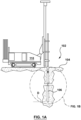
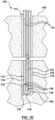
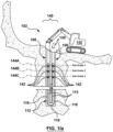
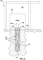
- FIGS. 1A to 1M show an illustrative method of installing a geothermal heat exchanger according to an aspect of the present disclosure.
- a borehole 106 is bored to a borehole target depth D in the site 102.
- a hydraulic drill rig 110 is used to form the borehole 106.
- a hydraulic drill rig may be equipped, for example, with a single, dual, or sonic top drive.
- a casing (not shown) may be used to stabilize the overburden (usually made up of clays, sands, and gravels for the most part), and an open hole (i.e. no casing) is drilled in the bedrock if encountered.
- a casing may be installed following drilling overburden where air or mud rotary drilling is used, or a casing may be installed simultaneously with drilling of the overburden using a rig equipped with dual rotary or sonic top drive, or with an overburden drilling system.
- Casing used in construction of a geothermal borehole is normally temporary casing, meaning that it is removed following installation of the geothermal heat exchanger into the borehole.
- the casing size must be large enough to accommodate the drill bit size used to drill the bedrock below; common sizes include 133 mm outside diameter (OD) (5.5”) and 165 mm OD (6.5").
- Bedrock is normally drilled with either down-the-hole hammer (for hard rock such as granite), or with PDC bits (for softer sedimentary rock).
- the fluid used to drill the rock is often compressed air but water or mud rotary drilling can also be used. Mud rotary drilling may also be used to drill an open hole in overburden, usually to a maximum depth of 150 metres and more frequently to depths of less than 100 metres. Mud rotary drilling of an open hole is not commonly used to greater depths because it becomes very difficult to maintain hole stability and to get the geothermal heat exchanger to the target depth.
- the borehole size is dictated by heat exchanger geometry and grouting requirements. Typical minimum borehole size for a 32 mm (1.25") single U-loop heat exchanger is 98 mm and for a 38 mm (1.5") single U-loop heat exchanger is 108 mm. Larger hole sizes are often used due to typical tooling of drilling equipment and 152 mm (6") is very common among water well drilling equipment. Boreholes are typically vertical but can be drilled in on an angle or directionally drilled using steerable drilling technology.
- a geothermal heat exchanger 112 is inserted into the borehole 106 to a desired heat exchanger depth, which may be the same as or slightly above the borehole depth D.
- the geothermal heat exchanger 112 is typically in the form of one or more tubular pipes in a U-shaped configuration (referred to as a "U-loop").
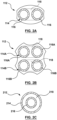
- the most common closed-loop geothermal heat exchanger configuration is a single U-loop, as shown in Figure 2A , which consists of two pipes 114 joined by a 180-degree elbow fitting 118 at the distal end of the heat exchanger 112 so as to form two continuous parallel arms 116 extending the length of the heat exchanger 112.
- Double U-loop configurations, as shown in Figure 2B are common in Europe, with two pairs of pipes 114A, 114B each joined by a respective 180-degree elbow fitting 118 to form two respective pairs of parallel arms 116A, 116B.
- an alternate form of geothermal heat exchanger 212 may be a concentric or coaxial heat exchanger comprising an outer tube 214 and an inner tube 216 in fluid communication with one another, with the outer tube 214 having a closed distal end 218 and the inner tube 216 having an open distal end that terminates short of the closed distal end 218 of the outer tube 214.
- Common U-loop pipe sizes range of 3 ⁇ 4" IPS to 1.5" IPS with wall thickness from SDR9 to SDR13.5 (SDR is the pipe diameter to wall thickness ratio).
- the most common pipe material is high density polyethylene, such as HDPE 3608 or HDPE 4710 although some other materials or thermally enhanced HDPE are used occasionally.
- the heat exchanger has a closed distal end (e.g. the elbow(s) 118 or the closed end 218 of the outer tube 214).
- the illustrative geothermal heat exchanger 112 is a single U-loop heat exchanger 112 comprising a flexible pipe 114 whose elbow 118 forms the closed distal end.
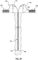
- Insertion of the geothermal heat exchanger 112 into the borehole 106 may be carried out manually, as shown in Figure 1B , or with a mechanical system 120, as shown in Figure 1Ba .
- Larger pipe diameters (e.g. 1.25" and 1.5") and deep boreholes usually make mechanical insertion necessary. Both manual and mechanical insertion are within the capability of one skilled in the art.
- the annular space 128 (see Figures 1C to 1E ) between the heat exchanger 112 and the wall of the borehole 106, as well as any space 130 between the arms 116 of the heat exchanger 112, is normally grouted using bentonite-based or cement-based grouts, with bentonite-based grouts being more common because of ease of use and improved performance.
- Thermal enhancement material is commonly used with bentonite-based grout to improve heat exchanger performance. These materials are typically silica sand and more recently, graphite material.
- the heat exchanger 112 is filled with an installation fluid 115 (such as water) maintained at a suitable pressure to maintain the structural integrity of the pipe 114 (i.e. prevent inward collapse).
- a tremie line 122 is inserted into the borehole 106.
- the pipe 114 and tremie line 122 will be fed off of respective coils 124, 126 and inserted at the same time (see Figures 1B and 1Ba ).
- the tremie line 122 may also be placed into the borehole following the insertion of the heat exchanger 112 into the borehole 106.
- the tremie line 122 is typically positioned between the arms 116 of the heat exchanger 112.
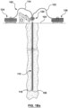
- the outlet end 132 of the tremie line 122 is initially positioned near the distal end of the heat exchanger, as shown in Figure 1C .
- the elbow 118 of the heat exchanger 112 may rest on a support 134 as shown, which support may double as a plumb-weight, or the elbow 118 of the heat exchanger 112 may rest directly on the bottom of the borehole 106, or the heat exchanger 112 may simply be suspended in the borehole 106 while the grout is applied.
- Grout 136 is injected into the borehole 106, as shown in Figure 1D , until the outlet end 132 of the tremie line 122 is submerged in the grout 136 several metres below the surface or meniscus of the grout 136. In this way, the grout 136 will push any water or other material out of the borehole 106, resulting in a continuous column of grout in the borehole 106. As the borehole 106 is grouted, the tremie line 122 is pulled back out of the borehole while keeping the outlet end of the tremie line 122 submerged in the grout 136 until the borehole 106 is substantially filled, as shown in Figure 1E .
- the excess length of the arms 116 of the pipe 114 that protrude beyond the mouth of the borehole 106 can be cut so that they are approximately flush with the surface of the substrate 104 in which the borehole 106 is formed, so as to provide the heat exchanger 112 with an open proximal end 138, as shown in (e.g.) Figure 1F .
- the pipe 114 can be pre-cut so that it will have a length corresponding to the depth of the borehole 106, or may be cut before grouting.
- grout is placed in the casing immediately prior to pulling the casing such that the grout has not yet 'set up' or stiffened so that the grout slumps out of the casing as it is pulled out of the borehole. As casing is pulled, grout is then used to top up the borehole so that the borehole is completely filled with grout once all casing has been extracted from the ground.
- the integrity of the heat exchanger 112, the depth of the heat exchanger 112, and potentially the quality of the grout 106 around the heat exchanger 112 may all be tested. Testing the depth and grout quality requires access to the heat exchanger 112 from the surface 104 of the site 102 to the full depth. Pressure testing also requires surface access and hydraulic continuity, but it does not necessarily require access to the bottom of loop, thereby allowing internal seals or plugs to be placed at some depth within the heat exchanger. The above testing is within the capability of one skilled in the art, now informed by the present disclosure. Thus, after securing the heat exchanger 112 in the borehole 106, the usual testing of the heat exchanger 112 can be carried out before excavation of the portion 140 ( Figure 1I ) of the site 102 immediately surrounding the borehole 106.
- the heat exchanger has a closed distal end (e.g. the elbow(s) 118 or the closed end 218 of the outer tube 214) and, at least after being secured in the borehole 106 after installation, has-an open proximal end 138 (e.g. the ends of the pipe(s) 114, 114A, 114B distal from the elbow(s) 118 or the end of (at least) the outer tube 214 remote from the closed distal end 218).
- the open proximal end 138 is proximal to the surface of the substrate 104 of the site 102.
- the heat exchanger 112 also has at least one fluid path between the closed distal end 118 and the open proximal end 138 (e.g. provided by the pipe(s) 114, 114A, 114B, 214, 216).
- notional subgrade depth refers to a depth below which no construction excavation is anticipated, at least within the portion 140 of the site 102 immediately surrounding the borehole 106. As a precaution, there may be multiple notional subgrade depths, with seals being placed below each, as described further below.
- portion of the site immediately surrounding the borehole refers to the region (portion of the site) that is within five meters, preferably within three meters and more preferably within one meter of the borehole 106, measured radially from the outer circumference of the borehole 106.
- Excavation of other portions of the site 102, i.e. those other than the portion 140 of the site 102 immediately surrounding the borehole 106, may be carried out before temporarily sealing the heat exchanger 112.
- other construction activities may proceed on other parts of the site 102 during, for example, formation of the borehole 106, installation of the heat exchanger 112 and grouting of the heat exchanger 112, before temporarily sealing the heat exchanger 112.
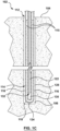
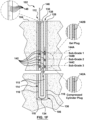
- the heat exchanger 112 is temporarily sealed between the closed distal end 118 (or 218) and the open proximal end 138 by installing, through the open proximal end 138, at least one respective internal seal in each fluid path, e.g. the pipe(s) 114 (or 114A, 114B, 214, 216).
- the internal seals may take a wide variety of forms, and may have a shape adapted to the particular type of heat exchanger.
- an internal seal may comprise one or more of a compressible foam ball plug 142 as shown in the main portion of Figure 1F , a compressible foam cylinder plug 142A as shown in the lower right side enlargement in Figure 1F , or a gel plug 142B as shown in the upper right side enlargement in Figure 1F , each of which is described further below.
- Each of the seals e.g. ball plugs 142 is disposed below a respective notional subgrade depth 144A, 144B, 144C.
- notional subgrade depths there may be multiple notional subgrade depths, with seals being placed at each.
- excavation will not continue below (e.g.) 10 meters from the surface 104, which would be a first notional subgrade depth 144A, but a second notional subgrade depth 144B of (e.g.) 10.5 meters and a third notional subgrade depth 144C of (e.g.) 11 meters may also be provided.
- ball plugs 142) are disposed between the first notional subgrade depth 144A and the second notional subgrade depth 144B, between the second notional subgrade depth 144B and the third notional subgrade depth 144C, and below the third notional subgrade depth 144C.
- seals e.g. ball plugs 142 disposed beneath each of the first notional subgrade depth 144A, the second notional subgrade depth 144B and the third notional subgrade depth 144C. Any desired number of notional subgrade depths and associated seals may be provided.
- the compressible foam ball plugs 142 may be placed below the desired subgrade depth 144A, 144B, 144C by forcing them along the interior of the pipes 114 using a rod 146 having depth markings 148.
- one or more seals may comprise a compressible foam cylinder 142A.
- the compressible foam cylinder plug 142A may simply be forced into position using the rod 146 similarly to the ball seals (e.g. ball plugs 142), or be compressed and vacuum-sealed inside an air-impermeable barrier membrane so as to form a compressed "packet" that can easily fit within the interior of the pipe 114. This packet can then be lowered to the desired depth and then the barrier membrane can be ruptured to permit the cylinder plug 142A to expand against the interior wall of the pipe 114.
- one or more seals may comprise a gel plug 142B.
- a gel plug 142B may comprise a sealed water-soluble tube filled with water absorbent yarn. The water soluble tube can be lowered to the desired depth and suspended in place using a string line. The water-soluble tube remains in place until it is dissolved, which then allows water to reach the water absorbent yarn. The yarn expands to fill the interior of the pipe 114 and provide a gel plug over a desired interval.
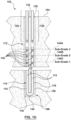
- each of the arms 116 of the pipe 114 is cut above the ball seals (e.g. ball plugs 142) positioned immediately below the first notional subgrade depth 144A.
- Cutting of the heat exchanger 112 may be carried out using any suitable technique; preferably, as shown in Figure 1G , the cutting is carried out by inserting a specialized pipe cutting tool 300 into the open proximal end 138 and cutting the heat exchanger 112 (e.g. cutting the arms 116 of the pipe 114) from the inside.
- the illustrative pipe cutting tool 300 comprises a main body 302 and a retractable cutting arm 304 and can be mounted on the end of the depth-marked rod 146 so that it can be advanced to the desired depth.
- the illustrative pipe cutting tool 300 which is not covered by the present invention, will be described in more detail below.
- cutting of the heat exchanger 112 produces two above-seal cut portions 150 (one for each arm 116 of the pipe 114) of the heat exchanger 112.
- the cut portions 150 are located above the uppermost seals, hence the term "above-seal"; in the illustrated embodiment this is above the ball seals (e.g. ball plugs 142) positioned immediately below the first notional subgrade depth 144A.
- the cut portions 150 of the heat exchanger 112 are then removed from the borehole 106, e.g.
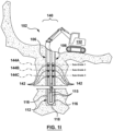
- cutting the heat exchanger 112 and removing each above-seal cut portion 150 of the heat exchanger 112 may be carried out during excavation of the portion 140 of the site 102 immediately surrounding the borehole 106. More particularly, depending on the material from which the heat exchanger 112 is constructed, it may be more efficient and cost effective to allow portions above the seals (i.e. above seal cut portions 150) to be severed and removed by the excavation process itself (e.g. by construction equipment such as an excavator, bulldozer, backhoe, etc.). Thus, cutting may be performed incidentally by excavating machinery 152 during excavation of the portion 140 of the site 102 immediately surrounding the borehole 106. This process is shown in Figure 1Ia .
- excavation can continue as long as the heat exchanger is not cut below the lowermost notional subgrade depth (i.e. excavation remains above the lowermost of the seal(s) 142 in the heat exchanger 112).
- the seals e.g. ball plugs 142
- the installation fluid 115 remains in the heat exchanger 112 during securing of the heat exchanger 112 in the borehole 106, and through temporarily sealing of the heat exchanger 112, cutting of the heat exchanger 112 and excavation of the portion 140 of the site 102 immediately surrounding the borehole 106.
- removal of the seals e.g.
- ball plugs 142) can be achieved by supplying pressurized fluid, denoted by arrow 154 in Figure 1K , at the open end 138 of one arm 116 of the heat exchanger 112 which will then force the ball plugs 142 (or other seals) out of the open end 138 of the other arm 116 of the heat exchanger 112.
- the seals e.g. ball plugs 142
- This permits a heat exchanger fluid e.g. water with corrosion inhibitor and antifreeze such as ethanol or propylene glycol
- arrows 166 e.g. water with corrosion inhibitor and antifreeze such as ethanol or propylene glycol
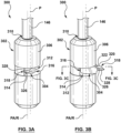
- the illustrative pipe cutting tool 300 comprises a main body 302 and a cutting arm 304.
- the main body 302 has an axially-extending outer guide surface 306 adapted to guide the main body 302 axially along the inside of a pipe 308 ( Figures 3C to 3E ) along a pipe axis PA ( Figures 3A to 3B ).
- the pipe axis PA corresponds to the longitudinal extent of the pipe 308.
- the main body 302 is substantially cylindrical with tapered ends although other shapes are contemplated; in other examples the guide surface may include bearings adapted to engage the inside of the pipe.
- One axial end of the main body 302 has an axially aligned drive rod recess 310 (see Figures 3D and 3E ) that is threaded for threadedly receiving a drive rod, such as the depth-marked rod 146, for driving the pipe cutting tool 300 along the inside of the pipe 308.
- a drive rod such as the depth-marked rod 146
- An arm recess 312 is formed in the guide surface 306 of the main body 302 to receive the cutting arm 304, and a stop surface 314 is disposed in the arm recess 312.
- the cutting arm 304 has a pivot end 316 and a cutting end 318 opposite the pivot end 316, with a back-edge 320 and a cutting edge 322 extending between the pivot end 316 and the cutting end 318.
- the back-edge 320 and a cutting edge 322 are generally opposed to one another.
- the pivot end 316 has a cam surface 324 and the cutting end 318 has a cutting head 326 disposed along the cutting edge 322.
- the cutting head 326 carries a blade 328 facing the cutting edge 322.
- the cutting head 326 may be adapted to receive a replaceable blade, or may have an integral blade, in which case the cutting head itself may be replaceable. Alternatively, the entire cutting arm 304 may be replaced if the blade 328 becomes dull.
- the cutting arm 304 is pivotally coupled at its pivot end 316 to the main body 302 within the arm recess 312 so as to be pivotable, relative to the main body 302, about a pivot axis P that is substantially parallel to the pipe axis PA.
- the pivot axis P of the cutting arm 304 is laterally offset from a central rotational axis R of the main body 302 that is, when the cutting tool 300 is inside the pipe 308, parallel to, and typically coincident with, the pipe axis PA.
- the pivot axis P of the cutting arm 304 will be laterally offset from the pipe axis PA.
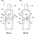
- the cutting arm 304 can pivot between a retracted position, as shown in Figures 3A , 3D , 3F, 3H and 3J , and an extended position, as shown in Figures 3B , 3C , 3E , 3G , 3I and 3K .
- the cutting arm 304 In the retracted position, the cutting arm 304 is retracted into the arm recess 312 so that the cutting edge 322 faces and may engage the stop surface 314.
- the cutting end 318 of the cutting arm 304 extends beyond the guide surface 306 to expose the cutting head 326 and the blade 328 and the cam surface 324 on the pivot end 316 engages the stop surface 314 to brace the cutting arm 304 against force applied to the cutting head 326 on the cutting edge side thereof (i.e. against pressure applied to the blade 328).
- the cutting arm 304 is pivotally coupled to the main body 302 by a pivot pin 330 passing through a pivot aperture 332 in the pivot end 316 of the cutting arm 304.
- One end 334 of the pivot pin 330 is received in a pivot pin recess 336 on the same axial side of the arm recess 312 as the drive rod recess 310 and the other end of the pivot pin 330 is received in a bushing receptacle 340.
- a bushing 342 (or alternatively a bearing such as a needle bearing) is disposed in the bushing receptacle 340 on the opposite axial side of the arm recess 312 from the drive rod recess 310, and the other end of the pivot pin 330 is journalled in the bushing 342.
- the bushing 342 is maintained in the bushing receptacle 340 by a setscrew 344 that is threadedly received in a setscrew recess 346 on the opposite axial side of the arm recess 312 from the drive rod recess 310. More particularly, the setscrew 344 traps the bushing 342 against a bushing shoulder 348.
- a biasing member acts between the main body 302 and the cutting arm 304 to urge the cutting arm 304 toward the extended position.
- the biasing member takes the form of a coil spring 350.
- the coil spring 350 surrounds the pivot pin 330; with one terminal arm of the coil spring 350 engaging the main body 302 and the other terminal arm of the coil spring 350 engaging the cutting arm 304.
- the cutting arm 304 is placed into the retracted position, and the cutting tool 300 is inserted into the inside of the pipe 308.
- the wall of the pipe 308 will maintain the cutting arm 304 substantially in the retracted position.
- the back-edge 320 of the cutting arm 304 will engage the inner surface 350 of the pipe 308, so that even if the cutting arm 304 moves slightly of the fully retracted position, the cutting arm 304 cannot move fully into the extended position and the cutting edge side of the cutting head 326 having the blade 328 is not exposed.
- rotating the main body 302 in the same direction that the cutting arm 304 pivots from the retracted position to the extended position can assist in preventing the cutting arm 304 from pivoting into the extended position.
- the cutting arm 304 can be moved into the extended position by rotating the main body 302 opposite to the direction that the cutting arm 304 pivots from the retracted position to the extended position, as shown by arrow 352 in Figures 3E and 3F . Because the pivot axis P is laterally offset from the central rotational axis R of the main body 302, this rotation will allow the cutting arm 304 to pivot, under urging from the coil spring 348, toward the extended position in which the cutting head 326 and the blade 328 are exposed. This is shown by arrow 354 in Figure 3G .
Landscapes
- Engineering & Computer Science (AREA)
- Life Sciences & Earth Sciences (AREA)
- Mechanical Engineering (AREA)
- Mining & Mineral Resources (AREA)
- Geology (AREA)
- General Life Sciences & Earth Sciences (AREA)
- General Engineering & Computer Science (AREA)
- Physics & Mathematics (AREA)
- Forests & Forestry (AREA)
- Combustion & Propulsion (AREA)
- Chemical & Material Sciences (AREA)
- Sustainable Energy (AREA)
- Sustainable Development (AREA)
- Environmental & Geological Engineering (AREA)
- Fluid Mechanics (AREA)
- Geochemistry & Mineralogy (AREA)
- Structural Engineering (AREA)
- Civil Engineering (AREA)
- Thermal Sciences (AREA)
- Earth Drilling (AREA)
- Heat-Exchange Devices With Radiators And Conduit Assemblies (AREA)
- Filling Or Discharging Of Gas Storage Vessels (AREA)
Applications Claiming Priority (1)
| Application Number | Priority Date | Filing Date | Title |
|---|---|---|---|
| US16/131,156 US11085670B2 (en) | 2018-09-14 | 2018-09-14 | Method and apparatus for installing geothermal heat exchanger |
Publications (4)
| Publication Number | Publication Date |
|---|---|
| EP3623723A2 EP3623723A2 (en) | 2020-03-18 |
| EP3623723A3 EP3623723A3 (en) | 2020-06-17 |
| EP3623723B1 true EP3623723B1 (en) | 2023-06-07 |
| EP3623723C0 EP3623723C0 (en) | 2023-06-07 |
Family
ID=67928694
Family Applications (1)
| Application Number | Title | Priority Date | Filing Date |
|---|---|---|---|
| EP19196678.7A Active EP3623723B1 (en) | 2018-09-14 | 2019-09-11 | Method for installing geothermal heat exchanger |
Country Status (7)
| Country | Link |
|---|---|
| US (3) | US11085670B2 (zh) |
| EP (1) | EP3623723B1 (zh) |
| JP (1) | JP7480978B2 (zh) |
| KR (1) | KR20200031530A (zh) |
| CN (1) | CN110906577B (zh) |
| CA (2) | CA3205872A1 (zh) |
| ES (1) | ES2955315T3 (zh) |
Families Citing this family (3)
| Publication number | Priority date | Publication date | Assignee | Title |
|---|---|---|---|---|
| NO343262B1 (en) * | 2016-07-22 | 2019-01-14 | Norges Miljoe Og Biovitenskapelige Univ Nmbu | Solar thermal collecting and storage |
| CA3051006A1 (en) * | 2017-02-10 | 2018-08-16 | Her Majesty The Queen In Right Of Canada As Represented By The Minister Of Natural Resources Canada | Multi-channel ground heat exchange unit and geothermal system |
| US20230272702A1 (en) * | 2022-02-28 | 2023-08-31 | Ur-Energy USA Inc. | System and method of using a thermoplastic casing in a wellbore |
Citations (1)
| Publication number | Priority date | Publication date | Assignee | Title |
|---|---|---|---|---|
| KR101658572B1 (ko) * | 2015-11-27 | 2016-09-21 | 한국건설기술연구원 | 지상연장부재의 제거를 이용한 지열교환 파이프의 시공방법 |
Family Cites Families (44)
| Publication number | Priority date | Publication date | Assignee | Title |
|---|---|---|---|---|
| US1088135A (en) | 1911-11-13 | 1914-02-24 | Robert Thomas Fagan | Welll-saw. |
| US1789995A (en) | 1926-11-03 | 1931-01-27 | Barkis Bruce | Casing cutting and pulling tool |
| US1927310A (en) | 1926-11-16 | 1933-09-19 | Charles R Edwards | Well cleaning apparatus |
| US1801424A (en) * | 1928-09-11 | 1931-04-21 | Gray Tool Co | Inside casing cutter |
| US2200172A (en) | 1937-07-10 | 1940-05-07 | Howard Clifford | Tubing cutter |
| US2208011A (en) | 1939-04-14 | 1940-07-16 | Baash Ross Tool Co | Inside tubing cutter |
| US3283405A (en) | 1964-02-05 | 1966-11-08 | Samuel P Braswell | Inside pipe cutting tool |
| US5253722A (en) | 1990-12-10 | 1993-10-19 | Laffkas Harry P | Impact borer for embedding lines, anchoring cables and sinking wells |
| AT404386B (de) | 1994-05-25 | 1998-11-25 | Johann Dipl Ing Springer | Doppelwandiger thermisch isolierter tubingstrang |
| US5634515A (en) | 1995-12-28 | 1997-06-03 | Lambert; Kenneth W. | Geothermal heat-pump system and installation of same |
| US6035949A (en) | 1998-02-03 | 2000-03-14 | Altschuler; Sidney J. | Methods for installing a well in a subterranean formation |
| JP3936963B2 (ja) | 2001-10-18 | 2007-06-27 | 独立行政法人産業技術総合研究所 | 地中熱交換器 |
| US6955219B2 (en) | 2003-07-03 | 2005-10-18 | Enlink Geoenergy Services, Inc. | Earth loop installation with sonic drilling |
| US7401641B1 (en) | 2004-05-24 | 2008-07-22 | Earth To Air Systems, Llc | Vertically oriented direct exchange/geothermal heating/cooling system sub-surface tubing installation means |
| US8136611B2 (en) | 2005-02-28 | 2012-03-20 | Roussy Raymond | Method and system for installing micropiles with a sonic drill |
| US20060191719A1 (en) | 2005-02-28 | 2006-08-31 | Roussy Raymond J | Method of geothermal loop installation |
| CZ307561B6 (cs) | 2007-04-18 | 2018-12-05 | imka Pavel Ĺ | Topný systém s gravitačním čerpacím zařízením a způsob gravitačního podtlakového čerpání tekutin |
| DE102007054185B3 (de) | 2007-11-14 | 2009-05-20 | Herold, Andreas, Dipl.-Ing. | Geothermiesonde und Verfahren zu deren Installation |
| US8118115B2 (en) * | 2008-02-22 | 2012-02-21 | Roussy Raymond J | Method and system for installing geothermal heat exchangers, micropiles, and anchors using a sonic drill and a removable or retrievable drill bit |
| KR100880675B1 (ko) | 2008-05-01 | 2009-01-30 | 주식회사 지앤지테크놀러지 | 이중 삽입 지열관을 이용한 폐쇄형 지중열교환기 장치 및구성 방법 |
| US9188368B2 (en) | 2009-02-04 | 2015-11-17 | Brooke Erin Desantis | Geothermal flexible conduit loop single pass installation system for dense soils and rock |
| WO2010122394A1 (en) * | 2009-04-20 | 2010-10-28 | Anzoic Energy Inc. | Subterranean continuous loop heat exchanger, method of manufacture and method to heat, cool or store energy with same |
| CA2704820A1 (en) | 2009-05-19 | 2010-11-19 | Thermapan Industries Inc. | Geothermal heat pump system |
| NL1037890C2 (nl) | 2010-04-06 | 2011-10-13 | Demar Heiwerken B V | Werkwijze voor het in een bodem inbrengen van een langwerpig element |
| US8672058B2 (en) * | 2009-07-14 | 2014-03-18 | Geothermal Technologies, Inc. | Method for repairing aberrations along a drill bore wall |
| US9103603B2 (en) * | 2009-10-28 | 2015-08-11 | Tai-Her Yang | Thermal conductive cylinder installed with U-type core piping and loop piping |
| WO2012051338A1 (en) | 2010-10-12 | 2012-04-19 | Vermeer Manufacturing Company | Systems and methods for installing geothermal energy transfer loops |
| JP5533620B2 (ja) | 2010-12-15 | 2014-06-25 | 株式会社大林組 | 地中熱交換器に係るu字管の地面の掘削孔への建て込み方法 |
| US20130087306A1 (en) | 2011-10-09 | 2013-04-11 | Bernard Meredith Winn, JR. | Forced Insertion Concentric Ground-Coupled Heat Exchanger for Ground Source Heat Pumps |
| US9109398B2 (en) | 2011-10-28 | 2015-08-18 | Mechanical & Electrical Concepts, Inc. | Method for forming a geothermal well |
| DE102012103499A1 (de) | 2012-04-20 | 2013-10-24 | Edward Michalik | Erdwärmesondenverlegeeinrichtung und Verschlussteil für diese |
| KR20130129722A (ko) | 2012-05-21 | 2013-11-29 | 주식회사 한국대체에너지 | 수팽창부재가 도포된 인케이싱을 이용한 개방형 지중열교환기의 시공방법 |
| WO2015030601A1 (en) | 2013-08-27 | 2015-03-05 | Geovarme As | A geothermal energy plant and a method for establishing same |
| JP6232962B2 (ja) | 2013-11-19 | 2017-11-22 | 株式会社大林組 | 管部材の建て込み方法 |
| US20170268803A1 (en) * | 2014-05-13 | 2017-09-21 | Charles J Cauchy | Direct insertion ground loop heat exchanger |
| KR101525431B1 (ko) * | 2015-03-04 | 2015-06-09 | 코텍엔지니어링주식회사 | 분리형 이음재를 이용한 터파기 전 보어홀 천공 공법 |
| DE102015204609A1 (de) | 2015-03-13 | 2016-09-15 | Pfeil Bauträger GmbH | Verfahren und Vorrichtungen zum Reparieren von Erdwärmesonden |
| KR101756753B1 (ko) | 2015-04-13 | 2017-07-11 | 삼보이엔씨 주식회사 | 커플링 구조체, 이를 포함하는 지열루프 구조체, 및 지열루프 시공방법 |
| JP2017083053A (ja) | 2015-10-27 | 2017-05-18 | 有限会社ジェイディエフ | 地中熱交換器設置用機材、地中熱交換器及び地中熱交換器設置方法 |
| KR101621751B1 (ko) | 2015-12-02 | 2016-05-17 | 코텍엔지니어링주식회사 | 가이드를 이용한 터 파기전 지중열 교환기 삽입 공법 |
| KR101640589B1 (ko) | 2016-02-01 | 2016-07-19 | 송진우 | 지열용 배관 절단 장치 |
| US20190086345A1 (en) | 2016-03-09 | 2019-03-21 | Geothermal Design Center Inc. | Advanced Ground Thermal Conductivity Testing |
| KR20170139739A (ko) | 2016-06-09 | 2017-12-20 | 코오롱환경서비스주식회사 | 단일관 밀폐 이음구를 이용한 지열배관 시공방법 |
| CA2977469A1 (en) * | 2016-08-26 | 2018-02-26 | Nuwave Industries Inc. | Tools and methods for setting a plug inside a pipe |
-
2018
- 2018-09-14 US US16/131,156 patent/US11085670B2/en active Active
- 2018-09-20 CA CA3205872A patent/CA3205872A1/en active Pending
- 2018-09-20 CA CA3018083A patent/CA3018083C/en active Active
-
2019
- 2019-09-05 CN CN201910835805.0A patent/CN110906577B/zh active Active
- 2019-09-09 KR KR1020190111626A patent/KR20200031530A/ko not_active Application Discontinuation
- 2019-09-11 ES ES19196678T patent/ES2955315T3/es active Active
- 2019-09-11 JP JP2019165076A patent/JP7480978B2/ja active Active
- 2019-09-11 EP EP19196678.7A patent/EP3623723B1/en active Active
-
2021
- 2021-07-06 US US17/367,688 patent/US11774145B2/en active Active
-
2023
- 2023-08-03 US US18/229,982 patent/US20230383999A1/en active Pending
Patent Citations (1)
| Publication number | Priority date | Publication date | Assignee | Title |
|---|---|---|---|---|
| KR101658572B1 (ko) * | 2015-11-27 | 2016-09-21 | 한국건설기술연구원 | 지상연장부재의 제거를 이용한 지열교환 파이프의 시공방법 |
Also Published As
| Publication number | Publication date |
|---|---|
| CN110906577A (zh) | 2020-03-24 |
| US11774145B2 (en) | 2023-10-03 |
| EP3623723A2 (en) | 2020-03-18 |
| CN110906577B (zh) | 2023-11-03 |
| EP3623723A3 (en) | 2020-06-17 |
| CA3018083A1 (en) | 2020-03-14 |
| KR20200031530A (ko) | 2020-03-24 |
| CA3018083C (en) | 2023-08-29 |
| US11085670B2 (en) | 2021-08-10 |
| CA3205872A1 (en) | 2020-03-14 |
| JP2020098089A (ja) | 2020-06-25 |
| US20230383999A1 (en) | 2023-11-30 |
| US20200088447A1 (en) | 2020-03-19 |
| US20210333020A1 (en) | 2021-10-28 |
| ES2955315T3 (es) | 2023-11-30 |
| JP7480978B2 (ja) | 2024-05-10 |
| EP3623723C0 (en) | 2023-06-07 |
Similar Documents
| Publication | Publication Date | Title |
|---|---|---|
| US11774145B2 (en) | Method and apparatus for installing geothermal heat exchanger | |
| EP2065554B1 (en) | System and method for drilling and completing lateral boreholes | |
| US8813844B2 (en) | System and method for drilling lateral boreholes | |
| US6536539B2 (en) | Shallow depth, coiled tubing horizontal drilling system | |
| RU2693805C2 (ru) | Система (варианты) и способ приповерхностной прокладки подземных кабелей или подземных линий в грунте | |
| US9631741B2 (en) | Casing puller | |
| JP2020098089A5 (zh) | ||
| CA2183675C (en) | Trenchless pipeline installation method with pilot hole corrective alignment | |
| MXPA02001401A (es) | Sistema de perforacion y terminacion para pozos multilaterales. | |
| CA2815739A1 (en) | Method for the underground installation of a pipe | |
| JP7385216B2 (ja) | 湧水圧測定装置および湧水圧測定方法 | |
| CN215672048U (zh) | 非开挖水平定向钻进铺管施工装置 | |
| CN115306300B (zh) | 一种水平长距离清障装置及全方位高压喷射注浆的方法 | |
| US20080164065A1 (en) | Construction of a Tubular at a Downhole Location | |
| JP2000248893A (ja) | 非開削による配管の敷設工法 | |
| Varghese et al. | A Review on Zero Degree Horizontal Directional Drilling | |
| NO20180235A1 (en) | A method and apparatus for simultaneously drilling and in-situ casing installation | |
| CN115199213A (zh) | 护筒埋设用可调节扩孔装置及施工工艺 | |
| US8851796B2 (en) | Pipe retriever | |
| JP2000248884A (ja) | 非開削による配管の敷設工法 |
Legal Events
| Date | Code | Title | Description |
|---|---|---|---|
| PUAI | Public reference made under article 153(3) epc to a published international application that has entered the european phase |
Free format text: ORIGINAL CODE: 0009012 |
|
| STAA | Information on the status of an ep patent application or granted ep patent |
Free format text: STATUS: THE APPLICATION HAS BEEN PUBLISHED |
|
| AK | Designated contracting states |
Kind code of ref document: A2 Designated state(s): AL AT BE BG CH CY CZ DE DK EE ES FI FR GB GR HR HU IE IS IT LI LT LU LV MC MK MT NL NO PL PT RO RS SE SI SK SM TR |
|
| AX | Request for extension of the european patent |
Extension state: BA ME |
|
| PUAL | Search report despatched |
Free format text: ORIGINAL CODE: 0009013 |
|
| AK | Designated contracting states |
Kind code of ref document: A3 Designated state(s): AL AT BE BG CH CY CZ DE DK EE ES FI FR GB GR HR HU IE IS IT LI LT LU LV MC MK MT NL NO PL PT RO RS SE SI SK SM TR |
|
| AX | Request for extension of the european patent |
Extension state: BA ME |
|
| RIC1 | Information provided on ipc code assigned before grant |
Ipc: F24T 10/15 20180101AFI20200512BHEP Ipc: E21B 29/00 20060101ALI20200512BHEP Ipc: F03G 7/00 20060101ALN20200512BHEP Ipc: B26D 5/02 20060101ALI20200512BHEP Ipc: F24T 10/00 20180101ALI20200512BHEP Ipc: B26D 1/30 20060101ALI20200512BHEP Ipc: B23D 21/14 20060101ALI20200512BHEP Ipc: F03G 7/04 20060101ALN20200512BHEP Ipc: B26D 3/16 20060101ALI20200512BHEP Ipc: F24T 10/40 20180101ALN20200512BHEP |
|
| STAA | Information on the status of an ep patent application or granted ep patent |
Free format text: STATUS: REQUEST FOR EXAMINATION WAS MADE |
|
| 17P | Request for examination filed |
Effective date: 20201217 |
|
| RBV | Designated contracting states (corrected) |
Designated state(s): AL AT BE BG CH CY CZ DE DK EE ES FI FR GB GR HR HU IE IS IT LI LT LU LV MC MK MT NL NO PL PT RO RS SE SI SK SM TR |
|
| GRAP | Despatch of communication of intention to grant a patent |
Free format text: ORIGINAL CODE: EPIDOSNIGR1 |
|
| STAA | Information on the status of an ep patent application or granted ep patent |
Free format text: STATUS: GRANT OF PATENT IS INTENDED |
|
| RIC1 | Information provided on ipc code assigned before grant |
Ipc: F03G 7/00 20060101ALN20211216BHEP Ipc: F03G 7/04 20060101ALN20211216BHEP Ipc: F24T 10/40 20180101ALN20211216BHEP Ipc: B26D 5/02 20060101ALI20211216BHEP Ipc: B26D 1/30 20060101ALI20211216BHEP Ipc: B23D 21/14 20060101ALI20211216BHEP Ipc: E21B 29/00 20060101ALI20211216BHEP Ipc: B26D 3/16 20060101ALI20211216BHEP Ipc: F24T 10/00 20180101ALI20211216BHEP Ipc: F24T 10/15 20180101AFI20211216BHEP |
|
| RIC1 | Information provided on ipc code assigned before grant |
Ipc: F03G 7/00 20060101ALN20211220BHEP Ipc: F03G 7/04 20060101ALN20211220BHEP Ipc: F24T 10/40 20180101ALN20211220BHEP Ipc: B26D 5/02 20060101ALI20211220BHEP Ipc: B26D 1/30 20060101ALI20211220BHEP Ipc: B23D 21/14 20060101ALI20211220BHEP Ipc: E21B 29/00 20060101ALI20211220BHEP Ipc: B26D 3/16 20060101ALI20211220BHEP Ipc: F24T 10/00 20180101ALI20211220BHEP Ipc: F24T 10/15 20180101AFI20211220BHEP |
|
| INTG | Intention to grant announced |
Effective date: 20220114 |
|
| GRAJ | Information related to disapproval of communication of intention to grant by the applicant or resumption of examination proceedings by the epo deleted |
Free format text: ORIGINAL CODE: EPIDOSDIGR1 |
|
| STAA | Information on the status of an ep patent application or granted ep patent |
Free format text: STATUS: REQUEST FOR EXAMINATION WAS MADE |
|
| INTC | Intention to grant announced (deleted) | ||
| GRAP | Despatch of communication of intention to grant a patent |
Free format text: ORIGINAL CODE: EPIDOSNIGR1 |
|
| STAA | Information on the status of an ep patent application or granted ep patent |
Free format text: STATUS: GRANT OF PATENT IS INTENDED |
|
| RIC1 | Information provided on ipc code assigned before grant |
Ipc: F03G 7/00 20060101ALN20220613BHEP Ipc: F03G 7/04 20060101ALN20220613BHEP Ipc: F24T 10/40 20180101ALN20220613BHEP Ipc: B26D 5/02 20060101ALI20220613BHEP Ipc: B26D 1/30 20060101ALI20220613BHEP Ipc: B23D 21/14 20060101ALI20220613BHEP Ipc: E21B 29/00 20060101ALI20220613BHEP Ipc: B26D 3/16 20060101ALI20220613BHEP Ipc: F24T 10/00 20180101ALI20220613BHEP Ipc: F24T 10/15 20180101AFI20220613BHEP |
|
| INTG | Intention to grant announced |
Effective date: 20220720 |
|
| GRAJ | Information related to disapproval of communication of intention to grant by the applicant or resumption of examination proceedings by the epo deleted |
Free format text: ORIGINAL CODE: EPIDOSDIGR1 |
|
| STAA | Information on the status of an ep patent application or granted ep patent |
Free format text: STATUS: REQUEST FOR EXAMINATION WAS MADE |
|
| GRAP | Despatch of communication of intention to grant a patent |
Free format text: ORIGINAL CODE: EPIDOSNIGR1 |
|
| STAA | Information on the status of an ep patent application or granted ep patent |
Free format text: STATUS: GRANT OF PATENT IS INTENDED |
|
| INTC | Intention to grant announced (deleted) | ||
| RIC1 | Information provided on ipc code assigned before grant |
Ipc: F03G 7/00 20060101ALN20221215BHEP Ipc: F03G 7/04 20060101ALN20221215BHEP Ipc: F24T 10/40 20180101ALN20221215BHEP Ipc: B26D 5/02 20060101ALI20221215BHEP Ipc: B26D 1/30 20060101ALI20221215BHEP Ipc: B23D 21/14 20060101ALI20221215BHEP Ipc: E21B 29/00 20060101ALI20221215BHEP Ipc: B26D 3/16 20060101ALI20221215BHEP Ipc: F24T 10/00 20180101ALI20221215BHEP Ipc: F24T 10/15 20180101AFI20221215BHEP |
|
| INTG | Intention to grant announced |
Effective date: 20230103 |
|
| GRAS | Grant fee paid |
Free format text: ORIGINAL CODE: EPIDOSNIGR3 |
|
| GRAA | (expected) grant |
Free format text: ORIGINAL CODE: 0009210 |
|
| STAA | Information on the status of an ep patent application or granted ep patent |
Free format text: STATUS: THE PATENT HAS BEEN GRANTED |
|
| AK | Designated contracting states |
Kind code of ref document: B1 Designated state(s): AL AT BE BG CH CY CZ DE DK EE ES FI FR GB GR HR HU IE IS IT LI LT LU LV MC MK MT NL NO PL PT RO RS SE SI SK SM TR |
|
| REG | Reference to a national code |
Ref country code: GB Ref legal event code: FG4D |
|
| REG | Reference to a national code |
Ref country code: CH Ref legal event code: EP Ref country code: AT Ref legal event code: REF Ref document number: 1576200 Country of ref document: AT Kind code of ref document: T Effective date: 20230615 Ref country code: DE Ref legal event code: R096 Ref document number: 602019029864 Country of ref document: DE |
|
| U01 | Request for unitary effect filed |
Effective date: 20230705 |
|
| U07 | Unitary effect registered |
Designated state(s): AT BE BG DE DK EE FI FR IT LT LU LV MT NL PT SE SI Effective date: 20230714 |
|
| REG | Reference to a national code |
Ref country code: LT Ref legal event code: MG9D |
|
| U20 | Renewal fee paid [unitary effect] |
Year of fee payment: 5 Effective date: 20230914 |
|
| PG25 | Lapsed in a contracting state [announced via postgrant information from national office to epo] |
Ref country code: NO Free format text: LAPSE BECAUSE OF FAILURE TO SUBMIT A TRANSLATION OF THE DESCRIPTION OR TO PAY THE FEE WITHIN THE PRESCRIBED TIME-LIMIT Effective date: 20230907 |
|
| PGFP | Annual fee paid to national office [announced via postgrant information from national office to epo] |
Ref country code: GB Payment date: 20230912 Year of fee payment: 5 |
|
| PG25 | Lapsed in a contracting state [announced via postgrant information from national office to epo] |
Ref country code: RS Free format text: LAPSE BECAUSE OF FAILURE TO SUBMIT A TRANSLATION OF THE DESCRIPTION OR TO PAY THE FEE WITHIN THE PRESCRIBED TIME-LIMIT Effective date: 20230607 Ref country code: HR Free format text: LAPSE BECAUSE OF FAILURE TO SUBMIT A TRANSLATION OF THE DESCRIPTION OR TO PAY THE FEE WITHIN THE PRESCRIBED TIME-LIMIT Effective date: 20230607 Ref country code: GR Free format text: LAPSE BECAUSE OF FAILURE TO SUBMIT A TRANSLATION OF THE DESCRIPTION OR TO PAY THE FEE WITHIN THE PRESCRIBED TIME-LIMIT Effective date: 20230908 |
|
| REG | Reference to a national code |
Ref country code: ES Ref legal event code: FG2A Ref document number: 2955315 Country of ref document: ES Kind code of ref document: T3 Effective date: 20231130 |
|
| PG25 | Lapsed in a contracting state [announced via postgrant information from national office to epo] |
Ref country code: SK Free format text: LAPSE BECAUSE OF FAILURE TO SUBMIT A TRANSLATION OF THE DESCRIPTION OR TO PAY THE FEE WITHIN THE PRESCRIBED TIME-LIMIT Effective date: 20230607 |
|
| PGFP | Annual fee paid to national office [announced via postgrant information from national office to epo] |
Ref country code: ES Payment date: 20231002 Year of fee payment: 5 |
|
| PG25 | Lapsed in a contracting state [announced via postgrant information from national office to epo] |
Ref country code: IS Free format text: LAPSE BECAUSE OF FAILURE TO SUBMIT A TRANSLATION OF THE DESCRIPTION OR TO PAY THE FEE WITHIN THE PRESCRIBED TIME-LIMIT Effective date: 20231007 |
|
| PG25 | Lapsed in a contracting state [announced via postgrant information from national office to epo] |
Ref country code: SM Free format text: LAPSE BECAUSE OF FAILURE TO SUBMIT A TRANSLATION OF THE DESCRIPTION OR TO PAY THE FEE WITHIN THE PRESCRIBED TIME-LIMIT Effective date: 20230607 Ref country code: SK Free format text: LAPSE BECAUSE OF FAILURE TO SUBMIT A TRANSLATION OF THE DESCRIPTION OR TO PAY THE FEE WITHIN THE PRESCRIBED TIME-LIMIT Effective date: 20230607 Ref country code: RO Free format text: LAPSE BECAUSE OF FAILURE TO SUBMIT A TRANSLATION OF THE DESCRIPTION OR TO PAY THE FEE WITHIN THE PRESCRIBED TIME-LIMIT Effective date: 20230607 Ref country code: IS Free format text: LAPSE BECAUSE OF FAILURE TO SUBMIT A TRANSLATION OF THE DESCRIPTION OR TO PAY THE FEE WITHIN THE PRESCRIBED TIME-LIMIT Effective date: 20231007 Ref country code: CZ Free format text: LAPSE BECAUSE OF FAILURE TO SUBMIT A TRANSLATION OF THE DESCRIPTION OR TO PAY THE FEE WITHIN THE PRESCRIBED TIME-LIMIT Effective date: 20230607 |
|
| PG25 | Lapsed in a contracting state [announced via postgrant information from national office to epo] |
Ref country code: PL Free format text: LAPSE BECAUSE OF FAILURE TO SUBMIT A TRANSLATION OF THE DESCRIPTION OR TO PAY THE FEE WITHIN THE PRESCRIBED TIME-LIMIT Effective date: 20230607 |
|
| REG | Reference to a national code |
Ref country code: DE Ref legal event code: R097 Ref document number: 602019029864 Country of ref document: DE |
|
| PLBE | No opposition filed within time limit |
Free format text: ORIGINAL CODE: 0009261 |
|
| STAA | Information on the status of an ep patent application or granted ep patent |
Free format text: STATUS: NO OPPOSITION FILED WITHIN TIME LIMIT |
|
| REG | Reference to a national code |
Ref country code: CH Ref legal event code: PL |
|
| 26N | No opposition filed |
Effective date: 20240308 |