EP3623162A1 - Antriebsmechanismus für einen fotodrucker - Google Patents
Antriebsmechanismus für einen fotodrucker Download PDFInfo
- Publication number
- EP3623162A1 EP3623162A1 EP19192614.6A EP19192614A EP3623162A1 EP 3623162 A1 EP3623162 A1 EP 3623162A1 EP 19192614 A EP19192614 A EP 19192614A EP 3623162 A1 EP3623162 A1 EP 3623162A1
- Authority
- EP
- European Patent Office
- Prior art keywords
- reduction
- gear
- rotary shaft
- reduction gears
- fitted
- Prior art date
- Legal status (The legal status is an assumption and is not a legal conclusion. Google has not performed a legal analysis and makes no representation as to the accuracy of the status listed.)
- Withdrawn
Links
Images


Classifications
-
- B—PERFORMING OPERATIONS; TRANSPORTING
- B41—PRINTING; LINING MACHINES; TYPEWRITERS; STAMPS
- B41J—TYPEWRITERS; SELECTIVE PRINTING MECHANISMS, i.e. MECHANISMS PRINTING OTHERWISE THAN FROM A FORME; CORRECTION OF TYPOGRAPHICAL ERRORS
- B41J11/00—Devices or arrangements of selective printing mechanisms, e.g. ink-jet printers or thermal printers, for supporting or handling copy material in sheet or web form
- B41J11/02—Platens
- B41J11/04—Roller platens
-
- B—PERFORMING OPERATIONS; TRANSPORTING
- B41—PRINTING; LINING MACHINES; TYPEWRITERS; STAMPS
- B41J—TYPEWRITERS; SELECTIVE PRINTING MECHANISMS, i.e. MECHANISMS PRINTING OTHERWISE THAN FROM A FORME; CORRECTION OF TYPOGRAPHICAL ERRORS
- B41J11/00—Devices or arrangements of selective printing mechanisms, e.g. ink-jet printers or thermal printers, for supporting or handling copy material in sheet or web form
- B41J11/02—Platens
- B41J11/14—Platen-shift mechanisms; Driving gear therefor
-
- B—PERFORMING OPERATIONS; TRANSPORTING
- B41—PRINTING; LINING MACHINES; TYPEWRITERS; STAMPS
- B41J—TYPEWRITERS; SELECTIVE PRINTING MECHANISMS, i.e. MECHANISMS PRINTING OTHERWISE THAN FROM A FORME; CORRECTION OF TYPOGRAPHICAL ERRORS
- B41J13/00—Devices or arrangements of selective printing mechanisms, e.g. ink-jet printers or thermal printers, specially adapted for supporting or handling copy material in short lengths, e.g. sheets
- B41J13/02—Rollers
- B41J13/03—Rollers driven, e.g. feed rollers separate from platen
-
- B—PERFORMING OPERATIONS; TRANSPORTING
- B41—PRINTING; LINING MACHINES; TYPEWRITERS; STAMPS
- B41J—TYPEWRITERS; SELECTIVE PRINTING MECHANISMS, i.e. MECHANISMS PRINTING OTHERWISE THAN FROM A FORME; CORRECTION OF TYPOGRAPHICAL ERRORS
- B41J2/00—Typewriters or selective printing mechanisms characterised by the printing or marking process for which they are designed
- B41J2/315—Typewriters or selective printing mechanisms characterised by the printing or marking process for which they are designed characterised by selective application of heat to a heat sensitive printing or impression-transfer material
- B41J2/32—Typewriters or selective printing mechanisms characterised by the printing or marking process for which they are designed characterised by selective application of heat to a heat sensitive printing or impression-transfer material using thermal heads
-
- B—PERFORMING OPERATIONS; TRANSPORTING
- B41—PRINTING; LINING MACHINES; TYPEWRITERS; STAMPS
- B41J—TYPEWRITERS; SELECTIVE PRINTING MECHANISMS, i.e. MECHANISMS PRINTING OTHERWISE THAN FROM A FORME; CORRECTION OF TYPOGRAPHICAL ERRORS
- B41J25/00—Actions or mechanisms not otherwise provided for
- B41J25/304—Bodily-movable mechanisms for print heads or carriages movable towards or from paper surface
- B41J25/312—Bodily-movable mechanisms for print heads or carriages movable towards or from paper surface with print pressure adjustment mechanisms, e.g. pressure-on-the paper mechanisms
-
- B—PERFORMING OPERATIONS; TRANSPORTING
- B41—PRINTING; LINING MACHINES; TYPEWRITERS; STAMPS
- B41J—TYPEWRITERS; SELECTIVE PRINTING MECHANISMS, i.e. MECHANISMS PRINTING OTHERWISE THAN FROM A FORME; CORRECTION OF TYPOGRAPHICAL ERRORS
- B41J29/00—Details of, or accessories for, typewriters or selective printing mechanisms not otherwise provided for
- B41J29/38—Drives, motors, controls or automatic cut-off devices for the entire printing mechanism
-
- B—PERFORMING OPERATIONS; TRANSPORTING
- B65—CONVEYING; PACKING; STORING; HANDLING THIN OR FILAMENTARY MATERIAL
- B65H—HANDLING THIN OR FILAMENTARY MATERIAL, e.g. SHEETS, WEBS, CABLES
- B65H3/00—Separating articles from piles
- B65H3/02—Separating articles from piles using friction forces between articles and separator
- B65H3/06—Rollers or like rotary separators
- B65H3/0669—Driving devices therefor
-
- F—MECHANICAL ENGINEERING; LIGHTING; HEATING; WEAPONS; BLASTING
- F16—ENGINEERING ELEMENTS AND UNITS; GENERAL MEASURES FOR PRODUCING AND MAINTAINING EFFECTIVE FUNCTIONING OF MACHINES OR INSTALLATIONS; THERMAL INSULATION IN GENERAL
- F16H—GEARING
- F16H57/00—General details of gearing
- F16H57/0006—Vibration-damping or noise reducing means specially adapted for gearings
-
- B—PERFORMING OPERATIONS; TRANSPORTING
- B41—PRINTING; LINING MACHINES; TYPEWRITERS; STAMPS
- B41J—TYPEWRITERS; SELECTIVE PRINTING MECHANISMS, i.e. MECHANISMS PRINTING OTHERWISE THAN FROM A FORME; CORRECTION OF TYPOGRAPHICAL ERRORS
- B41J2202/00—Embodiments of or processes related to ink-jet or thermal heads
- B41J2202/30—Embodiments of or processes related to thermal heads
- B41J2202/31—Thermal printer with head or platen movable
-
- B—PERFORMING OPERATIONS; TRANSPORTING
- B41—PRINTING; LINING MACHINES; TYPEWRITERS; STAMPS
- B41P—INDEXING SCHEME RELATING TO PRINTING, LINING MACHINES, TYPEWRITERS, AND TO STAMPS
- B41P2213/00—Arrangements for actuating or driving printing presses; Auxiliary devices or processes
- B41P2213/40—Auxiliary devices or processes associated with the drives
- B41P2213/44—Noise reduction
Definitions
- the present invention relates to a photo printer, and more particularly, to a driving mechanism for a photo printer that is capable of preventing gears fitted to a single shaft in parallel relation with each other from being repeatedly contacted with and separated from each other during rotation of the gears, thereby avoiding the generation of noise and vibrations from the gears and also improving a quality of print.
- a camera mounted on a smart device like a smartphone has similar performance to a general digital camera, and many people have taken their pictures with their smart device carried always with them, not with a digital camera. Accordingly, a consumer's desire to take his or her picture and to instantly print the picture, without any separate conversion, has been gradually increased.
- photo printers There are various kinds of photo printers. For example, there is a photo printer adopting a zero-ink printing technology using paper expressing colors in response to heat, and there is a photo printer adopting an ink ribbon technology using an ink ribbon responding to heat.
- FIG.1 is a sectional view showing a conventional photo printer.
- the conventional photo printer includes a frame 110, a paper accommodating part 111 coupled between both side walls of the frame 110 to stackedly accommodate paper therein, a pickup roller R1 disposed protrudingly from a bottom surface of the paper accommodating part 111, a platen roller R2 coupled to the frame 110 to discharge the paper fed by the pickup roller R1 forward, and a thermal printing head 141 disposed above the platen roller R2 to apply given heat to the paper.
- an inclined guide portion 112 is formed on the front end of the paper accommodating part 111 to guide the paper between the head 141 and the platen roller R2.
- the head 141 is coupled to a bracket 151 so that it can be rotatably coupled to the frame, and a pressurizing plate 161 is disposed above the bracket 151.
- a spring S is connected between the pressurizing plate 161 and a front frame 115 to elastically pull the head 141 downward.
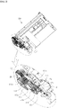
- FIG.2 is a driving mechanism for transferring the paper in the conventional photo printer.
- the driving mechanism includes a motor M, a motor pinion 171, first to fifth reduction gears 172 to 176, and a final gear 177.
- the motor pinion 171 is coupled to the motor M, and each of the first to fifth reduction gears 172 to 176 has a shape of a double gear having double gear teeth diameters on a common axis. Further, the final gear 177 is fitted to the platen roller R2.
- a rotary force of the motor M is transferred to the motor pinion 171, and the motor pinion 171 engages with a first gear 172 of the first reduction gear.
- a second gear 172a of the first reduction gear engages with a first gear 173 of the second reduction gear
- a second gear 173a of the second reduction gear engages with a first gear 174 of the third reduction gear.
- a second gear 174a of the third reduction gear engages with a first gear 175 of the fourth reduction gear
- a second gear 175a of the fourth reduction gear engages with a first gear 176 of the fifth reduction gear.
- a second gear 176a of the fifth reduction gear engages with the final gear 177, so that the rotary force of the motor M is transferred to the platen roller R2.
- the first reduction gears 172 and 172a and the third reduction gears 174 and 174a are fitted to a single common rotary shaft SH1.
- the second reduction gears 173 and 173a and the fourth reduction gears 175 and 175a are fitted to a common rotary shaft SH2.
- only the fifth reduction gear is fitted to a rotary shaft SH3.
- the rotary shaft SH1 is coupled to the frame F, and the first reduction gears 172 and 172a and the third reduction gears 174 and 174a are sequentially fitted to the rotary shaft SH1 in parallel relation with each other.
- a snap ring (e.g., C ring) C is fitted to an end periphery of the rotary shaft SH1.
- the snap ring C is a fixing member for preventing the reduction gears from being separated from the rotary shaft SH1.
- a length of the rotary shaft SH1 has to be greater than a width of the first reduction gears 172 and 172a and the third reduction gears 174 and 174a (d2>d1). If the length of the rotary shaft SH1 is equal to or less than the width of the first reduction gears 172 and 172a and the third reduction gears 174 and 174a, the snap ring C cannot be fitted to the end periphery of the rotary shaft SH1, thereby making it impossible to fixedly couple the reduction gears to the rotary shaft SH1.
- the first reduction gears 172 and 172a engaging with the motor pinion 171 rotate at a high speed
- the second reduction gears 173 and 173a and the third reduction gears 174 and 174a rotate at different rotation ratios.
- the first reduction gears 172 and 172a and the third reduction gears 174 and 174a move to left and right sides along the rotary shaft SH1 by means of the gap d3 formed by the difference between the length d2 of the rotary shaft SH1 and the width d1 of the first reduction gears 172 and 172a and the third reduction gears 174 and 174a.
- Such movements cause the third reduction gear 174 and the first reduction gear 172a to be repeatedly contacted with and separated from each other, and as the third reduction gear 174 collides against the side of the first reduction gear 172a, at this time, collision sounds and vibrations may be generated (See FIGS.3B and 3C ).
- noise may be generated at the time of photo print, and set rotation ratio values may be changed due to the movements and vibrations of the gears, thereby making a quality of print deteriorated.
- first reduction gears 172 and 172a and the third reduction gears 174 and 174a are fitted to one rotary shaft SH1, like this, the first reduction gear 172a and the third reduction gear 174 having different rotation ratios come into contact with each other, thereby having an influence on their rotation speed.
- the rotary force is transferred to the first reduction gears 172 and 172a disposed in the parallel relation with the third reduction gears 174 and 174a, so that the first reduction gears 172 and 172a also rotate.
- a transferring speed of the paper becomes different from a given transferring speed, thereby undesirably making a quality of print deteriorated.
- a driving mechanism for a photo printer having a frame for accommodating paper therein and a platen roller coupled to the frame to transfer paper
- the driving mechanism including: a motor for providing a rotary force to the platen roller; a motor pinion disposed on one side of the frame to output the rotary force of the motor; at least one or more reduction gears coupled to a side wall of the frame to reduce the rotary force of the motor pinion; a final gear coupled to the platen roller to receive the reduced rotary force from the reduction gears; and a pressurizing member for elastically pressurizing the reduction gears against the side wall of the frame.
- the driving mechanism further includes a fixing member fitted to an end periphery of a rotary shaft having the reduction gears fitted thereto to prevent the reduction gears from being separated from the rotary shaft, and the pressurizing member is disposed between the reduction gears and the fixing member.
- the driving mechanism further includes a washer between the pressurizing member and the reduction gears.
- the pressurizing member includes any one of a coil spring, elastic rubber, and elastic sponge adapted to pass the rotary shaft of the reduction gears therethrough.
Landscapes
- Engineering & Computer Science (AREA)
- Mechanical Engineering (AREA)
- General Engineering & Computer Science (AREA)
- Sheets, Magazines, And Separation Thereof (AREA)
- Gear Transmission (AREA)
Applications Claiming Priority (1)
| Application Number | Priority Date | Filing Date | Title |
|---|---|---|---|
| KR1020180108586A KR20200029950A (ko) | 2018-09-11 | 2018-09-11 | 포토 프린터의 구동장치 |
Publications (1)
| Publication Number | Publication Date |
|---|---|
| EP3623162A1 true EP3623162A1 (de) | 2020-03-18 |
Family
ID=67659500
Family Applications (1)
| Application Number | Title | Priority Date | Filing Date |
|---|---|---|---|
| EP19192614.6A Withdrawn EP3623162A1 (de) | 2018-09-11 | 2019-08-20 | Antriebsmechanismus für einen fotodrucker |
Country Status (3)
| Country | Link |
|---|---|
| US (1) | US20200079118A1 (de) |
| EP (1) | EP3623162A1 (de) |
| KR (1) | KR20200029950A (de) |
Citations (6)
| Publication number | Priority date | Publication date | Assignee | Title |
|---|---|---|---|---|
| JPH04115660U (ja) * | 1991-03-28 | 1992-10-14 | 株式会社タムラ製作所 | ラインプリンタにおける駆動力伝達装置 |
| JPH05221044A (ja) * | 1992-02-13 | 1993-08-31 | Toshiba Corp | 感熱記録装置 |
| JPH0723555U (ja) * | 1993-10-07 | 1995-05-02 | グラフテック株式会社 | 熱転写記録装置 |
| US6004053A (en) * | 1998-09-11 | 1999-12-21 | Comtec Informationsystems, Inc. | Printer apparatus |
| US20030076401A1 (en) * | 2001-10-23 | 2003-04-24 | Fujitsu Component Limited | Thermal printer |
| KR20170082432A (ko) * | 2016-06-01 | 2017-07-14 | 디에스글로벌 (주) | 포토 프린터용 엔진 |
-
2018
- 2018-09-11 KR KR1020180108586A patent/KR20200029950A/ko not_active Ceased
-
2019
- 2019-08-20 US US16/545,377 patent/US20200079118A1/en not_active Abandoned
- 2019-08-20 EP EP19192614.6A patent/EP3623162A1/de not_active Withdrawn
Patent Citations (6)
| Publication number | Priority date | Publication date | Assignee | Title |
|---|---|---|---|---|
| JPH04115660U (ja) * | 1991-03-28 | 1992-10-14 | 株式会社タムラ製作所 | ラインプリンタにおける駆動力伝達装置 |
| JPH05221044A (ja) * | 1992-02-13 | 1993-08-31 | Toshiba Corp | 感熱記録装置 |
| JPH0723555U (ja) * | 1993-10-07 | 1995-05-02 | グラフテック株式会社 | 熱転写記録装置 |
| US6004053A (en) * | 1998-09-11 | 1999-12-21 | Comtec Informationsystems, Inc. | Printer apparatus |
| US20030076401A1 (en) * | 2001-10-23 | 2003-04-24 | Fujitsu Component Limited | Thermal printer |
| KR20170082432A (ko) * | 2016-06-01 | 2017-07-14 | 디에스글로벌 (주) | 포토 프린터용 엔진 |
Also Published As
| Publication number | Publication date |
|---|---|
| US20200079118A1 (en) | 2020-03-12 |
| KR20200029950A (ko) | 2020-03-19 |
Similar Documents
| Publication | Publication Date | Title |
|---|---|---|
| EP4628439A3 (de) | Drucker und druckkassette | |
| EP1900536B1 (de) | Leistungsübertragungsverfahren und Vorrichtung, Vorrichtung zur Entladung eines Mediums damit und Bilderzeugungsvorrichtung mit der Vorrichtung zur Entladung eines Mediums | |
| EP3623162A1 (de) | Antriebsmechanismus für einen fotodrucker | |
| US5704606A (en) | Sheet feeding apparatus for a printer | |
| EP0795412B1 (de) | Motor mit einer von mehreren Schneckengetrieben versehenen Antriebswelle für einen Drucker | |
| US7607844B2 (en) | Image forming apparatus | |
| US11267262B2 (en) | Printer | |
| US20070086827A1 (en) | Printer | |
| US20070040322A1 (en) | Image generating apparatus | |
| US8262089B1 (en) | Depinching mechanism for paper jam removal in printer | |
| JP3538869B2 (ja) | プリンタ | |
| JPS587470B2 (ja) | インジヨウシオクリソウチ | |
| JPS6013656Y2 (ja) | インクリボンのテンシヨン装置 | |
| EP1496001A1 (de) | Blattfördervorrichtung | |
| JPS61116563A (ja) | プリンタの紙送り機構 | |
| JP4525688B2 (ja) | 画像形成装置 | |
| JP3885969B2 (ja) | 画像形成装置 | |
| JP2005081717A (ja) | キャリッジ保持装置およびインクジェット式画像形成装置 | |
| JP3820527B2 (ja) | 画像形成装置 | |
| JP2007212934A (ja) | 画像形成装置 | |
| KR100497490B1 (ko) | 화상형성장치의 픽업 구동장치 | |
| KR20190061112A (ko) | 감속기어의 간섭이 없는 포토 프린터 | |
| JP2003176055A (ja) | ローラ駆動機構及びそのローラ駆動機構を備えたインクジェット記録装置 | |
| JPH04280265A (ja) | 多色画像形成装置 | |
| JP2006347117A (ja) | 記録装置 |
Legal Events
| Date | Code | Title | Description |
|---|---|---|---|
| PUAI | Public reference made under article 153(3) epc to a published international application that has entered the european phase |
Free format text: ORIGINAL CODE: 0009012 |
|
| STAA | Information on the status of an ep patent application or granted ep patent |
Free format text: STATUS: REQUEST FOR EXAMINATION WAS MADE |
|
| 17P | Request for examination filed |
Effective date: 20190820 |
|
| AK | Designated contracting states |
Kind code of ref document: A1 Designated state(s): AL AT BE BG CH CY CZ DE DK EE ES FI FR GB GR HR HU IE IS IT LI LT LU LV MC MK MT NL NO PL PT RO RS SE SI SK SM TR |
|
| AX | Request for extension of the european patent |
Extension state: BA ME |
|
| STAA | Information on the status of an ep patent application or granted ep patent |
Free format text: STATUS: THE APPLICATION HAS BEEN WITHDRAWN |
|
| 18W | Application withdrawn |
Effective date: 20201023 |