EP3623100A1 - Procédés de fabrication de pale à racine forgée - Google Patents
Procédés de fabrication de pale à racine forgée Download PDFInfo
- Publication number
- EP3623100A1 EP3623100A1 EP19195215.9A EP19195215A EP3623100A1 EP 3623100 A1 EP3623100 A1 EP 3623100A1 EP 19195215 A EP19195215 A EP 19195215A EP 3623100 A1 EP3623100 A1 EP 3623100A1
- Authority
- EP
- European Patent Office
- Prior art keywords
- root
- airfoil
- machining
- cooling
- solution heat
- Prior art date
- Legal status (The legal status is an assumption and is not a legal conclusion. Google has not performed a legal analysis and makes no representation as to the accuracy of the status listed.)
- Pending
Links
Images


Classifications
-
- F—MECHANICAL ENGINEERING; LIGHTING; HEATING; WEAPONS; BLASTING
- F01—MACHINES OR ENGINES IN GENERAL; ENGINE PLANTS IN GENERAL; STEAM ENGINES
- F01D—NON-POSITIVE DISPLACEMENT MACHINES OR ENGINES, e.g. STEAM TURBINES
- F01D5/00—Blades; Blade-carrying members; Heating, heat-insulating, cooling or antivibration means on the blades or the members
- F01D5/12—Blades
- F01D5/14—Form or construction
- F01D5/147—Construction, i.e. structural features, e.g. of weight-saving hollow blades
-
- B—PERFORMING OPERATIONS; TRANSPORTING
- B21—MECHANICAL METAL-WORKING WITHOUT ESSENTIALLY REMOVING MATERIAL; PUNCHING METAL
- B21J—FORGING; HAMMERING; PRESSING METAL; RIVETING; FORGE FURNACES
- B21J1/00—Preparing metal stock or similar ancillary operations prior, during or post forging, e.g. heating or cooling
- B21J1/06—Heating or cooling methods or arrangements specially adapted for performing forging or pressing operations
-
- B—PERFORMING OPERATIONS; TRANSPORTING
- B21—MECHANICAL METAL-WORKING WITHOUT ESSENTIALLY REMOVING MATERIAL; PUNCHING METAL
- B21J—FORGING; HAMMERING; PRESSING METAL; RIVETING; FORGE FURNACES
- B21J5/00—Methods for forging, hammering, or pressing; Special equipment or accessories therefor
- B21J5/002—Hybrid process, e.g. forging following casting
-
- B—PERFORMING OPERATIONS; TRANSPORTING
- B21—MECHANICAL METAL-WORKING WITHOUT ESSENTIALLY REMOVING MATERIAL; PUNCHING METAL
- B21J—FORGING; HAMMERING; PRESSING METAL; RIVETING; FORGE FURNACES
- B21J5/00—Methods for forging, hammering, or pressing; Special equipment or accessories therefor
- B21J5/008—Incremental forging
-
- B—PERFORMING OPERATIONS; TRANSPORTING
- B21—MECHANICAL METAL-WORKING WITHOUT ESSENTIALLY REMOVING MATERIAL; PUNCHING METAL
- B21J—FORGING; HAMMERING; PRESSING METAL; RIVETING; FORGE FURNACES
- B21J5/00—Methods for forging, hammering, or pressing; Special equipment or accessories therefor
- B21J5/02—Die forging; Trimming by making use of special dies ; Punching during forging
-
- B—PERFORMING OPERATIONS; TRANSPORTING
- B21—MECHANICAL METAL-WORKING WITHOUT ESSENTIALLY REMOVING MATERIAL; PUNCHING METAL
- B21K—MAKING FORGED OR PRESSED METAL PRODUCTS, e.g. HORSE-SHOES, RIVETS, BOLTS OR WHEELS
- B21K3/00—Making engine or like machine parts not covered by sub-groups of B21K1/00; Making propellers or the like
- B21K3/04—Making engine or like machine parts not covered by sub-groups of B21K1/00; Making propellers or the like blades, e.g. for turbines; Upsetting of blade roots
-
- B—PERFORMING OPERATIONS; TRANSPORTING
- B23—MACHINE TOOLS; METAL-WORKING NOT OTHERWISE PROVIDED FOR
- B23P—METAL-WORKING NOT OTHERWISE PROVIDED FOR; COMBINED OPERATIONS; UNIVERSAL MACHINE TOOLS
- B23P15/00—Making specific metal objects by operations not covered by a single other subclass or a group in this subclass
- B23P15/02—Making specific metal objects by operations not covered by a single other subclass or a group in this subclass turbine or like blades from one piece
-
- C—CHEMISTRY; METALLURGY
- C21—METALLURGY OF IRON
- C21D—MODIFYING THE PHYSICAL STRUCTURE OF FERROUS METALS; GENERAL DEVICES FOR HEAT TREATMENT OF FERROUS OR NON-FERROUS METALS OR ALLOYS; MAKING METAL MALLEABLE, e.g. BY DECARBURISATION OR TEMPERING
- C21D9/00—Heat treatment, e.g. annealing, hardening, quenching or tempering, adapted for particular articles; Furnaces therefor
- C21D9/0068—Heat treatment, e.g. annealing, hardening, quenching or tempering, adapted for particular articles; Furnaces therefor for particular articles not mentioned below
-
- C—CHEMISTRY; METALLURGY
- C22—METALLURGY; FERROUS OR NON-FERROUS ALLOYS; TREATMENT OF ALLOYS OR NON-FERROUS METALS
- C22F—CHANGING THE PHYSICAL STRUCTURE OF NON-FERROUS METALS AND NON-FERROUS ALLOYS
- C22F1/00—Changing the physical structure of non-ferrous metals or alloys by heat treatment or by hot or cold working
- C22F1/002—Changing the physical structure of non-ferrous metals or alloys by heat treatment or by hot or cold working by rapid cooling or quenching; cooling agents used therefor
-
- C—CHEMISTRY; METALLURGY
- C22—METALLURGY; FERROUS OR NON-FERROUS ALLOYS; TREATMENT OF ALLOYS OR NON-FERROUS METALS
- C22F—CHANGING THE PHYSICAL STRUCTURE OF NON-FERROUS METALS AND NON-FERROUS ALLOYS
- C22F1/00—Changing the physical structure of non-ferrous metals or alloys by heat treatment or by hot or cold working
- C22F1/10—Changing the physical structure of non-ferrous metals or alloys by heat treatment or by hot or cold working of nickel or cobalt or alloys based thereon
-
- C—CHEMISTRY; METALLURGY
- C30—CRYSTAL GROWTH
- C30B—SINGLE-CRYSTAL GROWTH; UNIDIRECTIONAL SOLIDIFICATION OF EUTECTIC MATERIAL OR UNIDIRECTIONAL DEMIXING OF EUTECTOID MATERIAL; REFINING BY ZONE-MELTING OF MATERIAL; PRODUCTION OF A HOMOGENEOUS POLYCRYSTALLINE MATERIAL WITH DEFINED STRUCTURE; SINGLE CRYSTALS OR HOMOGENEOUS POLYCRYSTALLINE MATERIAL WITH DEFINED STRUCTURE; AFTER-TREATMENT OF SINGLE CRYSTALS OR A HOMOGENEOUS POLYCRYSTALLINE MATERIAL WITH DEFINED STRUCTURE; APPARATUS THEREFOR
- C30B11/00—Single-crystal growth by normal freezing or freezing under temperature gradient, e.g. Bridgman-Stockbarger method
-
- C—CHEMISTRY; METALLURGY
- C30—CRYSTAL GROWTH
- C30B—SINGLE-CRYSTAL GROWTH; UNIDIRECTIONAL SOLIDIFICATION OF EUTECTIC MATERIAL OR UNIDIRECTIONAL DEMIXING OF EUTECTOID MATERIAL; REFINING BY ZONE-MELTING OF MATERIAL; PRODUCTION OF A HOMOGENEOUS POLYCRYSTALLINE MATERIAL WITH DEFINED STRUCTURE; SINGLE CRYSTALS OR HOMOGENEOUS POLYCRYSTALLINE MATERIAL WITH DEFINED STRUCTURE; AFTER-TREATMENT OF SINGLE CRYSTALS OR A HOMOGENEOUS POLYCRYSTALLINE MATERIAL WITH DEFINED STRUCTURE; APPARATUS THEREFOR
- C30B29/00—Single crystals or homogeneous polycrystalline material with defined structure characterised by the material or by their shape
- C30B29/10—Inorganic compounds or compositions
- C30B29/52—Alloys
-
- C—CHEMISTRY; METALLURGY
- C30—CRYSTAL GROWTH
- C30B—SINGLE-CRYSTAL GROWTH; UNIDIRECTIONAL SOLIDIFICATION OF EUTECTIC MATERIAL OR UNIDIRECTIONAL DEMIXING OF EUTECTOID MATERIAL; REFINING BY ZONE-MELTING OF MATERIAL; PRODUCTION OF A HOMOGENEOUS POLYCRYSTALLINE MATERIAL WITH DEFINED STRUCTURE; SINGLE CRYSTALS OR HOMOGENEOUS POLYCRYSTALLINE MATERIAL WITH DEFINED STRUCTURE; AFTER-TREATMENT OF SINGLE CRYSTALS OR A HOMOGENEOUS POLYCRYSTALLINE MATERIAL WITH DEFINED STRUCTURE; APPARATUS THEREFOR
- C30B33/00—After-treatment of single crystals or homogeneous polycrystalline material with defined structure
- C30B33/02—Heat treatment
-
- F—MECHANICAL ENGINEERING; LIGHTING; HEATING; WEAPONS; BLASTING
- F01—MACHINES OR ENGINES IN GENERAL; ENGINE PLANTS IN GENERAL; STEAM ENGINES
- F01D—NON-POSITIVE DISPLACEMENT MACHINES OR ENGINES, e.g. STEAM TURBINES
- F01D5/00—Blades; Blade-carrying members; Heating, heat-insulating, cooling or antivibration means on the blades or the members
- F01D5/30—Fixing blades to rotors; Blade roots ; Blade spacers
- F01D5/3007—Fixing blades to rotors; Blade roots ; Blade spacers of axial insertion type
-
- B—PERFORMING OPERATIONS; TRANSPORTING
- B23—MACHINE TOOLS; METAL-WORKING NOT OTHERWISE PROVIDED FOR
- B23H—WORKING OF METAL BY THE ACTION OF A HIGH CONCENTRATION OF ELECTRIC CURRENT ON A WORKPIECE USING AN ELECTRODE WHICH TAKES THE PLACE OF A TOOL; SUCH WORKING COMBINED WITH OTHER FORMS OF WORKING OF METAL
- B23H9/00—Machining specially adapted for treating particular metal objects or for obtaining special effects or results on metal objects
- B23H9/10—Working turbine blades or nozzles
-
- C—CHEMISTRY; METALLURGY
- C21—METALLURGY OF IRON
- C21D—MODIFYING THE PHYSICAL STRUCTURE OF FERROUS METALS; GENERAL DEVICES FOR HEAT TREATMENT OF FERROUS OR NON-FERROUS METALS OR ALLOYS; MAKING METAL MALLEABLE, e.g. BY DECARBURISATION OR TEMPERING
- C21D2221/00—Treating localised areas of an article
-
- C—CHEMISTRY; METALLURGY
- C21—METALLURGY OF IRON
- C21D—MODIFYING THE PHYSICAL STRUCTURE OF FERROUS METALS; GENERAL DEVICES FOR HEAT TREATMENT OF FERROUS OR NON-FERROUS METALS OR ALLOYS; MAKING METAL MALLEABLE, e.g. BY DECARBURISATION OR TEMPERING
- C21D2261/00—Machining or cutting being involved
-
- F—MECHANICAL ENGINEERING; LIGHTING; HEATING; WEAPONS; BLASTING
- F01—MACHINES OR ENGINES IN GENERAL; ENGINE PLANTS IN GENERAL; STEAM ENGINES
- F01D—NON-POSITIVE DISPLACEMENT MACHINES OR ENGINES, e.g. STEAM TURBINES
- F01D5/00—Blades; Blade-carrying members; Heating, heat-insulating, cooling or antivibration means on the blades or the members
- F01D5/34—Rotor-blade aggregates of unitary construction, e.g. formed of sheet laminae
-
- F—MECHANICAL ENGINEERING; LIGHTING; HEATING; WEAPONS; BLASTING
- F05—INDEXING SCHEMES RELATING TO ENGINES OR PUMPS IN VARIOUS SUBCLASSES OF CLASSES F01-F04
- F05D—INDEXING SCHEME FOR ASPECTS RELATING TO NON-POSITIVE-DISPLACEMENT MACHINES OR ENGINES, GAS-TURBINES OR JET-PROPULSION PLANTS
- F05D2230/00—Manufacture
- F05D2230/10—Manufacture by removing material
- F05D2230/11—Manufacture by removing material by electrochemical methods
-
- F—MECHANICAL ENGINEERING; LIGHTING; HEATING; WEAPONS; BLASTING
- F05—INDEXING SCHEMES RELATING TO ENGINES OR PUMPS IN VARIOUS SUBCLASSES OF CLASSES F01-F04
- F05D—INDEXING SCHEME FOR ASPECTS RELATING TO NON-POSITIVE-DISPLACEMENT MACHINES OR ENGINES, GAS-TURBINES OR JET-PROPULSION PLANTS
- F05D2230/00—Manufacture
- F05D2230/10—Manufacture by removing material
- F05D2230/12—Manufacture by removing material by spark erosion methods
-
- F—MECHANICAL ENGINEERING; LIGHTING; HEATING; WEAPONS; BLASTING
- F05—INDEXING SCHEMES RELATING TO ENGINES OR PUMPS IN VARIOUS SUBCLASSES OF CLASSES F01-F04
- F05D—INDEXING SCHEME FOR ASPECTS RELATING TO NON-POSITIVE-DISPLACEMENT MACHINES OR ENGINES, GAS-TURBINES OR JET-PROPULSION PLANTS
- F05D2230/00—Manufacture
- F05D2230/20—Manufacture essentially without removing material
- F05D2230/21—Manufacture essentially without removing material by casting
- F05D2230/211—Manufacture essentially without removing material by casting by precision casting, e.g. microfusing or investment casting
-
- F—MECHANICAL ENGINEERING; LIGHTING; HEATING; WEAPONS; BLASTING
- F05—INDEXING SCHEMES RELATING TO ENGINES OR PUMPS IN VARIOUS SUBCLASSES OF CLASSES F01-F04
- F05D—INDEXING SCHEME FOR ASPECTS RELATING TO NON-POSITIVE-DISPLACEMENT MACHINES OR ENGINES, GAS-TURBINES OR JET-PROPULSION PLANTS
- F05D2230/00—Manufacture
- F05D2230/20—Manufacture essentially without removing material
- F05D2230/25—Manufacture essentially without removing material by forging
-
- F—MECHANICAL ENGINEERING; LIGHTING; HEATING; WEAPONS; BLASTING
- F05—INDEXING SCHEMES RELATING TO ENGINES OR PUMPS IN VARIOUS SUBCLASSES OF CLASSES F01-F04
- F05D—INDEXING SCHEME FOR ASPECTS RELATING TO NON-POSITIVE-DISPLACEMENT MACHINES OR ENGINES, GAS-TURBINES OR JET-PROPULSION PLANTS
- F05D2230/00—Manufacture
- F05D2230/40—Heat treatment
-
- F—MECHANICAL ENGINEERING; LIGHTING; HEATING; WEAPONS; BLASTING
- F05—INDEXING SCHEMES RELATING TO ENGINES OR PUMPS IN VARIOUS SUBCLASSES OF CLASSES F01-F04
- F05D—INDEXING SCHEME FOR ASPECTS RELATING TO NON-POSITIVE-DISPLACEMENT MACHINES OR ENGINES, GAS-TURBINES OR JET-PROPULSION PLANTS
- F05D2230/00—Manufacture
- F05D2230/90—Coating; Surface treatment
-
- F—MECHANICAL ENGINEERING; LIGHTING; HEATING; WEAPONS; BLASTING
- F05—INDEXING SCHEMES RELATING TO ENGINES OR PUMPS IN VARIOUS SUBCLASSES OF CLASSES F01-F04
- F05D—INDEXING SCHEME FOR ASPECTS RELATING TO NON-POSITIVE-DISPLACEMENT MACHINES OR ENGINES, GAS-TURBINES OR JET-PROPULSION PLANTS
- F05D2240/00—Components
- F05D2240/20—Rotors
- F05D2240/30—Characteristics of rotor blades, i.e. of any element transforming dynamic fluid energy to or from rotational energy and being attached to a rotor
-
- F—MECHANICAL ENGINEERING; LIGHTING; HEATING; WEAPONS; BLASTING
- F05—INDEXING SCHEMES RELATING TO ENGINES OR PUMPS IN VARIOUS SUBCLASSES OF CLASSES F01-F04
- F05D—INDEXING SCHEME FOR ASPECTS RELATING TO NON-POSITIVE-DISPLACEMENT MACHINES OR ENGINES, GAS-TURBINES OR JET-PROPULSION PLANTS
- F05D2300/00—Materials; Properties thereof
- F05D2300/10—Metals, alloys or intermetallic compounds
- F05D2300/17—Alloys
- F05D2300/175—Superalloys
Definitions
- the disclosure relates to turbomachine blade manufacture. More particularly, the disclosure relates to manufacture of metallic blades for gas turbines and associated high pressure compressors.
- United States Patent Application Publication 20170130289A1 (the '289 publication), Shah et al., published May 11, 2017, and entitled “High Elastic Modulus Shafts and Method of Manufacture", discloses a turbine engine shaft manufacture wherein a cylinder is hot worked into a shaft form.
- United States Patent Application Publication 20170088926A1 (the '926 publication), Shah et al., March 30, 2017, and entitled "Nickel Based Superalloy With High Volume Fraction of Precipitate Phase” discloses approaches to swage single crystal bars without the intervention of recrystallization.
- One aspect of the disclosure involves a method for manufacturing a blade.
- the method comprises: casting a nickel alloy blade precursor having an airfoil and a root; solution heat treating the airfoil and the root differently from each other; after the solution heat treating, wrought processing of the root; and after the wrought processing, machining an exterior of the root.
- a further embodiment of any of the foregoing embodiments may additionally and/or alternatively include the casting forming cooling passageways in the airfoil.
- a further embodiment of any of the foregoing embodiments may additionally and/or alternatively include machining feed passageways in the root to join the cooling passageways in the airfoil.
- a further embodiment of any of the foregoing embodiments may additionally and/or alternatively include the machining the exterior comprising mechanical grinding and electro-chemical machining; and the machining feed passageways comprising electro-discharge machining.
- a further embodiment of any of the foregoing embodiments may additionally and/or alternatively include the solution heat treating providing the root with larger average gamma prime size than the average gamma prime size of the airfoil.
- a further embodiment of any of the foregoing embodiments may additionally and/or alternatively include the solution heat treating providing the root with at least 2.0 times the average gamma prime size than the average gamma prime size of the airfoil.
- a further embodiment of any of the foregoing embodiments may additionally and/or alternatively include the solution heat treating comprising: fully solutioning and cooling the airfoil and root; and resolutioning the root while isolating the airfoil from the resolution heating.
- a further embodiment of any of the foregoing embodiments may additionally and/or alternatively include the solution heat treating comprising: heating and cooling the airfoil and root; and heating the root while isolating the airfoil from the heating.
- a further embodiment of any of the foregoing embodiments may additionally and/or alternatively include the solution heat treating comprising: heating the airfoil and root; and cooling the airfoil while isolating the root from the cooling so as to cool more slowly.
- a further embodiment of any of the foregoing embodiments may additionally and/or alternatively include the wrought processing comprising a sequence of individual transverse cross-sectional area reductions of at least 4%.
- a further embodiment of any of the foregoing embodiments may additionally and/or alternatively include the wrought processing comprising alternating transverse compactions and heatings.
- a further embodiment of any of the foregoing embodiments may additionally and/or alternatively include the wrought processing comprising at least 10 swagings.
- a further embodiment of any of the foregoing embodiments may additionally and/or alternatively include the thermally isolating comprising active cooling.
- a further embodiment of any of the foregoing embodiments may additionally and/or alternatively include the wrought processing being effective to provide 10%-75% reduction in cross-sectional area.
- a further embodiment of any of the foregoing embodiments may additionally and/or alternatively include the machining leaving the root as a firtree root.
- a further embodiment of any of the foregoing embodiments may additionally and/or alternatively include the machining comprising grinding.
- a further embodiment of any of the foregoing embodiments may additionally and/or alternatively include the machining leaving the root as having a firtree portion and a spoke portion of greater radial span than the firtree portion.
- a further embodiment of any of the foregoing embodiments may additionally and/or alternatively include the machining comprising grinding.
- a further embodiment of any of the foregoing embodiments may additionally and/or alternatively include a method for manufacturing a bladed disk.
- the method includes manufacturing as above a plurality of blades and further comprises mounting the blades in a powder metallurgical (PM) disk.
- PM powder metallurgical
- a further embodiment of any of the foregoing embodiments may additionally and/or alternatively include the mounting comprising at least one of transient liquid phase bonding (TLP), inertial friction welding, and mechanical attachments via fir-tree type or dovetail type attachment.
- TLP transient liquid phase bonding
- inertial friction welding inertial friction welding
- mechanical attachments via fir-tree type or dovetail type attachment via fir-tree type or dovetail type attachment.
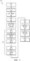
- FIG. 1 shows a process 20 for blade manufacture.
- the process may depart from a conventional casting in that there is wrought processing of a root precursor to facilitate advantageous root properties (e.g., low cycle fatigue properties).
- advantageous root properties e.g., low cycle fatigue properties
- the departure from a baseline process may first prepare a casing with differential airfoil v. root precursor properties to facilitate the wrought processing.
- An initial casting step 22 casts a blade precursor 120 ( FIG. 2 ).
- the blade precursor is cast from a nickel-based superalloy and has an airfoil 122 and a root 124.
- the airfoil is a precursor of the final airfoil but still airfoil shaped (e.g., subject to trimming at the tip or gating and then finish machining).
- the precursor also includes a platform 126 forming a precursor of the ultimate blade platform.
- the airfoil 122 extends along a span from an inboard (radially inboard in the ultimate engine frame of reference) end at an outboard surface of the platform 126 to a tip 130.
- An outward radial direction or spanwise direction 510 is also shown.
- FIG. 2 further shows the airfoil as extending from a leading edge 132 to a trailing edge 134 and having a pressure side and a suction side.
- the root 124 is a precursor of the final root but not having the basic root shape (e.g., may be a block-like shape such as a cylinder (e.g., right circular cylinder or rectangular cylinder/prismatic shape) having no convolutions of a fir tree shape of the ultimate blade root).
- the root precursor or stub 124 has a cylindrical section 140 extending to an inboard end 142.
- a transition section 144 extends between the outboard end of the cylindrical section and the underside of the platform.
- the transition section may serve two purposes. First, as is discussed below, it may form a reduced thickness (in at least one transverse dimension) region whose thickness the portion 140 is ultimately thinned down toward.
- its transverse cross-section (e.g., normal to the spanwise direction 510) may transition between the shape of the cylinder 140 and a footprint more appropriately configured to transfer loads between the ultimate root and the airfoil. Thus, it may transition from relatively circular at the portion 140 to relatively rectangular at the platform underside.
- the exemplary casting is an investment casting process using a casting core (e.g., ceramic or a combination of ceramic and refractory metal core(s)(RMC)) 150 to form cooling passageways 152 in the airfoil.
- the exemplary casting step does not form passageways in the root precursor or stub. This is a second possible departure from a baseline process that has a ceramic core forming passageways extending through the root and airfoil. As-cast, the casting has dendritic microstructure throughout.
- a deshelling/decoring step 24 (e.g., mechanical deshelling and alkaline and/ or acid decoring) may leave a raw casting.
- a grit blasting 26 may clean up residual shell/core. The amount of grit blasting may be limited to avoid subsequent recrystallization. Gating removal 28 may be via sawing.
- the subsequent heat treatment 40A; 40B is configured to convert the microstructure from dendritic to homogeneous while optimizing relative gamma prime sizes in the airfoil and root stub. Maximization of creep resistance in the airfoil is associated with relatively fine precipitate structure at the solution heat treatment stage (e.g., gamma prime in airfoil is finally coarsened to 0.3-0.5 micrometer for optimum creep properties after subsequent coating diffusion and other heat treatment cycles). Workability of the root stub is associated with larger/coarser average gamma prime (e.g., 2.0-3.0 micrometers, more broadly, at least 0.5 micrometer or at least 1.0 micrometer or 0.5-5.0 micrometers or 1.0-4.0 micrometers). Exemplary average precipitate size in the root stub may be 1.5 or more times that of the airfoil, more particularly at least 2.0 or at least 5.0, or an exemplary 5.0-20.0 or 5.0-10.0.
- Exemplary average precipitate size in the root stub may
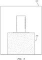
- a first differential heat treating option 40A ( FIG. 1A ) involves applying 42 insulation 200 ( FIG. 3 ) to the root stub.
- insulation 200 FIG. 3
- blanket-form ceramic fiber alumina-silica material with low thermal conductivity e.g., FIBERFRAX material from Unifrax I LLC, Tonawanda, NY.
- Ni-based superalloy having nominal composition by weight percent of 5.0 Cr, 1.9 Mo, 5.9 W, 8.7 Ta, 5.65 Al, 10.0 Co, 3.0 Re, 0.1 Hf, balance Ni.
- Table I below lists further SX candidates mostly drawn from the '963 patent. Compositional ranges of superalloys encompassing these individual table entries may also be relevant.
- the blade with root stub insulation is placed in a heat treat furnace 220 and slowly heated 46 to elevate an elevated temperature (e.g., to a temperature of 1310°C over a time of at least 6 hours to ramp up to solutioning temperature).
- the casting is held isothermally 48 (e.g., 4 hours, more broadly, at least 2.0 hours) and homogenizes.
- the temperature is 2400°F (1316°C) for 4 hours to fully solution.
- the heating and hold/dwell are long enough so that there is little or no observable difference in effect on microstructure.
- a rapid cool/quench 50 follows (e.g., using an argon gas stream). In the absence of insulation, the airfoil cools quickly as in a conventional rapid quench.
- the insulated root stub cools much more slowly allowing the growth of larger gamma prime to impart the workability.
- the slow stub cooling is at a rate of 0.3°F (0.17°C) per minute down to a threshold temperature of 2000°F (1093°C). Once at this threshold a more rapid cooling 52 may occur such as by opening the furnace and opening/removing the insulation.
- An alternative second option 40B involves performing a conventional solution heat treat to the whole casting to homogenize 60. This is followed by a uniform rapid quench/cooling 62. To differentiate the root stub microstructure, the root stub may then be preferentially heated 64 (distinguished from the preferential cooling 50 of the airfoil in the first option 40A). The heating is to solution temperature (e.g., either using induction heating or conventional heating) and then heat input is reduced to achieve a desired cooling rate. In this process the airfoil area is kept below the temperature where no significant change in microstructure occurs.
- This preferential heating 64 may involve some combination of localizing energy input to the root stub, insulating the airfoil, or active cooling of the airfoil.
- FIG. 4 shows a furnace 250 similar to those used for directional solidification of single crystal castings. The casting may be inserted from below until the root stub area is in the hot section 252 of the furnace (e.g., surrounded by the susceptor 254 and induction coil(s) 256). The airfoil is in the cold section of the furnace (e.g. below a baffle). An optional conformal cooling jacket 260 carrying a flow 264 of water or other heat transfer liquid may capture and cool 70 the airfoil while the stub is heated 64. It is understood that in industrial practice, multiple articles may be heat treated as a batch and different active cooling and heating schemes could be applied.
- exemplary root stub heating 64 is to a temperature of 2390°F (1310°C).
- Exemplary cool-down 72 time and rate are 22 hours and 0.3°F/minute (0.17°C/minute) to 2000°F (1093°C) .
- the result is to leave the casting with the difference in gamma prime precipitate sizes discussed above.
- the airfoil may have the solution heat treated microstructure normally required for maximum creep resistance and the root stub has a super-overage microstructure which facilitates large deformation for the subsequent working.
- Exemplary working 76 is a swaging process. Swaging is multi-step process with an initial preheating 78-1 and reheatings 78-2...78-n between individual swagings 80-1...80-n. The result is that root stub dislocation density is greatly increased in order to improve fatigue properties. It may require a post-swage (pre- or post-machining 80) heat treatment 82 at temperatures up to 2000°F (1093°C).
- the blade may be heated to temperature below the recrystallization temperature or at the temperature at which the super-overage heat treatment was ended to anneal.
- an exemplary temperature is 1900°F to 1950°F (1038°C to 1066°C).
- the root stub is swaged using a die set reducing the cross-sectional area (e.g., lengthening the root stub to reduce cross section transverse to a span-wise direction of the airfoil).
- the blade is preferably annealed 78-2...78-n at the temperature at which the super-overage heat treatment was ended.
- An exemplary number "n" of swagings is 5 to 40 or 10 to 30 or 15 to 30.
- swaging machine typically four split dies sit in its fast spinning core and resist opening when a metal piece of larger diameter is inserted, thereby causing reduction in diameter by impact.
- These dies typically have a tapered entrance to facilitate insertion of a cylindrical metal of slightly larger diameter than the die's exit diameter. Once the cylinder passes through the dies, the diameter is reduced close to the exit diameter. In most cases a cylindrical metal rod is inserted through the die and exits at the other end to swage down the entire length of the rod.
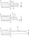
- FIG. 5 shows a partial (local) swage of a 0.75 inch (19 mm) diameter D single crystal rod by about 56% to a reduced diameter d of about 0.33 inch (8.4 mm) leaving a transition between swages and unswagged material. Swaging the root stub area may be similarly performed with the transition region (144 and/or an outboard portion of 140) being progressively less swaged toward the platform underside.
- Normal swaging dies have a long tapered entrance but the dies can be inserted in the machine with the tapered end towards the exit to reduce the transition zone between the swaged stub and the platform. Or, as shown in many standard handbooks, a different die design can be used to achieve a reduced transition zone. For an example, in a typical swaging machine to reduce a 1.5 inch (38mm) diameter cylinder by a 50% reduction in diameter (to 0.75 inch (19mm)) or 75% reduction in cross-sectional area, about twenty-three die sets are required. Each die set reduces the diameter by approximately 0.035 inch (0.89mm). This amounts to about 6.8% reduction in area and 7.3 % increase in length.
- exemplary per-swaging transverse area cross-sectional area reduction is 4% to 12% or 5% to 10%.
- Overall transverse area cross-sectional area reduction may be 25% to 90% or 50% to 85%.
- FIG. 2 shows a pre-swage blade precursor.
- FIG. 6 shows a post-swage blade precursor with elongated/thinned root stub 124'.
- the root stub may have a near circular cylindrical form due to the swaging.
- the resulting FIG. 6 length of the stub portion from the original cylinder is 8 inches (203mm).
- the overall stub length is over 8 inches (203mm) due to the material of the transition section.
- FIG. 7 shows the final root after cutting away 90 excess stub length at the root inboard end 158 grinding in or electro-discharge machining 92 the fir tree or profile 160, and machining 94 feed passageway trunks 170.
- a multi-layer ceramic thermal barrier coating (TBC) system may be applied 98 in a multi-step process involving several spray or vapor deposition stages for the ceramic preceded by similar such stages or plating of metallic or other bondcoat.
- FIG. 8 shows an example where a long spoke section 180 having a length H S is left between the fir tree and the platform underside.
- a swaged spoke may offer improved strength and fatigue resistance relative to a cast spoke.
- swaging may be used to expand the design space for a longer and thinner spoke and a thinner fir tree thereby reducing the blade weight and/or reducing the blade pull exerted on the disk.
- the at least short spoke (e.g., H S at least 2 inch (5.1 cm) or an exemplary 6 inch (15 cm) to 12 inch (30 cm)) provides a gap between the turbine blade platform and the disk.
- This gap may improve thermal mechanical fatigue performance (TMF) of the disk because the disk outer diameter (OD) rim surface is shifted radially inward and away from the hot gas path.
- TMF thermal mechanical fatigue performance
- a swaged spoke may better resist stress corrosion cracking in the corrosive environment of a secondary airflow. It has been shown that swaged single crystal is at least 100°F (56°C) better in creep resistance than some of the best powder material disk alloys currently used.
- a reheat (not shown e.g., but similar to 78-1 through 78-n) may be performed prior to a bending operation to form a hook.
- Hook final machining may replace the profile machining 92.
- cogging Akin to swaging are other processes called cogging where instead of a round cross section, even square or hexagonal cross sections can be processed.
- cogging For processing single crystal or coarse grain material, though such processes are likely to present additional challenges in terms of secondary crystal orientation and grain size distribution, respectively.
- cogging in ⁇ 110> secondary direction is preferable.
- Hot die forging is typically performed on a single crystal (SX) part by heating the SX part at ⁇ 2000°F (1093°C), transferring and placing the SX part to between a pair of dies preheated to 1400-1600°F (760-871°C) and deforming or forging the SX part at strain rates in the range of 0.1 s -1 ⁇ strain rate ⁇ 10 s -1 in one or more increments.
- the total deformation (strain) may be approximately in the range 50-80%.
- Individual cross-sectional area reductions per forging step may be similar to those above for each swaging or cogging step.
- An advantage of hot die forging is that fairly complex part geometry can be achieved as a result of the forging process without the intervention of cracking or recrystallization phenomena. Minimization of the "die chilling" effect leads to significant improvement in hot workability (compared to the situation wherein the dies are at room temperature).
- ⁇ 010> and ⁇ 100> would be normal thereto. It may be desirable to have the ⁇ 010> and ⁇ 100> with a predetermined relationship to the airfoil so that the swagings may then have a predetermined relationship with the ⁇ 010> and ⁇ 100> directions.
- Dovetail or firtree mountings may be axially mechanically retained to the disk via clamping.
- Alternative mounting comprises bonding such as transient liquid phase bonding (TLP) or inertial friction welding (optionally in combination with and mechanical interlocking attachments such as firtree type or dovetail type attachments).
- TLP transient liquid phase bonding
- inertial friction welding optionally in combination with and mechanical interlocking attachments such as firtree type or dovetail type attachments.
- first, second, and the like in the following claims is for differentiation within the claim only and does not necessarily indicate relative or absolute importance or temporal order. Similarly, the identification in a claim of one element as “first” (or the like) does not preclude such "first” element from identifying an element that is referred to as “second” (or the like) in another claim or in the description.
Landscapes
- Engineering & Computer Science (AREA)
- Chemical & Material Sciences (AREA)
- Mechanical Engineering (AREA)
- Crystallography & Structural Chemistry (AREA)
- Materials Engineering (AREA)
- Metallurgy (AREA)
- Organic Chemistry (AREA)
- Thermal Sciences (AREA)
- Physics & Mathematics (AREA)
- General Engineering & Computer Science (AREA)
- Architecture (AREA)
- Inorganic Chemistry (AREA)
- Turbine Rotor Nozzle Sealing (AREA)
Applications Claiming Priority (1)
| Application Number | Priority Date | Filing Date | Title |
|---|---|---|---|
| US16/131,451 US11306595B2 (en) | 2018-09-14 | 2018-09-14 | Wrought root blade manufacture methods |
Publications (1)
| Publication Number | Publication Date |
|---|---|
| EP3623100A1 true EP3623100A1 (fr) | 2020-03-18 |
Family
ID=67850966
Family Applications (1)
| Application Number | Title | Priority Date | Filing Date |
|---|---|---|---|
| EP19195215.9A Pending EP3623100A1 (fr) | 2018-09-14 | 2019-09-03 | Procédés de fabrication de pale à racine forgée |
Country Status (2)
| Country | Link |
|---|---|
| US (2) | US11306595B2 (fr) |
| EP (1) | EP3623100A1 (fr) |
Cited By (1)
| Publication number | Priority date | Publication date | Assignee | Title |
|---|---|---|---|---|
| RU2744005C1 (ru) * | 2020-05-09 | 2021-03-01 | Федеральное государственное бюджетное образовательное учреждение высшего образования. "Юго-Западный государственный университет" (ЮЗГУ) | Способ электроискрового легирования лопаток из титановых сплавов паровых турбин ТЭЦ и АЭС |
Families Citing this family (1)
| Publication number | Priority date | Publication date | Assignee | Title |
|---|---|---|---|---|
| US11306595B2 (en) * | 2018-09-14 | 2022-04-19 | Raytheon Technologies Corporation | Wrought root blade manufacture methods |
Citations (13)
| Publication number | Priority date | Publication date | Assignee | Title |
|---|---|---|---|---|
| US4514360A (en) | 1982-12-06 | 1985-04-30 | United Technologies Corporation | Wrought single crystal nickel base superalloy |
| US4528048A (en) | 1982-12-06 | 1985-07-09 | United Technologies Corporation | Mechanically worked single crystal article |
| GB2152076A (en) * | 1983-12-27 | 1985-07-31 | United Technologies Corp | Improved forgeability in nickel base superalloys |
| EP0513407A1 (fr) * | 1991-05-13 | 1992-11-19 | Asea Brown Boveri Ag | Procédé de fabrication d' une aube de turbine |
| US5190603A (en) * | 1990-07-04 | 1993-03-02 | Asea Brown Boveri Ltd. | Process for producing a workpiece from an alloy containing dopant and based on titanium aluminide |
| US8147749B2 (en) | 2005-03-30 | 2012-04-03 | United Technologies Corporation | Superalloy compositions, articles, and methods of manufacture |
| US20130108445A1 (en) | 2011-10-28 | 2013-05-02 | Gabriel L. Suciu | Spoked rotor for a gas turbine engine |
| WO2013143995A1 (fr) * | 2012-03-27 | 2013-10-03 | Alstom Technology Ltd | Procédé pour fabriquer des composants constitués de superalliages à base de nickel monocristallins (sx) ou solidifiés de façon directionnelle (ds) |
| JP2014047389A (ja) * | 2012-08-31 | 2014-03-17 | Hitachi Ltd | 発電用ガスタービン用動翼と、熱処理方法 |
| US9138963B2 (en) | 2009-12-14 | 2015-09-22 | United Technologies Corporation | Low sulfur nickel base substrate alloy and overlay coating system |
| US20170088926A1 (en) | 2015-09-28 | 2017-03-30 | United Technologies Corporation | Nickel Based Superalloy With High Volume Fraction of Precipitate Phase |
| US20170130289A1 (en) | 2012-08-28 | 2017-05-11 | United Technologies Corporation | High Elastic Modulus Shafts and Method of Manufacture |
| EP3178959A1 (fr) * | 2015-12-10 | 2017-06-14 | Ansaldo Energia Switzerland AG | Procédé de traitement de solution thermique pour la fabrication de composants métalliques d'une turbomachine |
Family Cites Families (12)
| Publication number | Priority date | Publication date | Assignee | Title |
|---|---|---|---|---|
| FR979187A (fr) * | 1948-01-15 | 1951-04-23 | Perfectionnements apportés aux procédés et dispositifs de fabrication des aubes de turbines, compresseurs et autres machines analogues | |
| US2928650A (en) * | 1953-11-20 | 1960-03-15 | Bristol Aero Engines Ltd | Rotor assemblies for gas turbine engines |
| US4680160A (en) * | 1985-12-11 | 1987-07-14 | Trw Inc. | Method of forming a rotor |
| US7338259B2 (en) | 2004-03-02 | 2008-03-04 | United Technologies Corporation | High modulus metallic component for high vibratory operation |
| US7784183B2 (en) * | 2005-06-09 | 2010-08-31 | General Electric Company | System and method for adjusting performance of manufacturing operations or steps |
| US7741576B2 (en) * | 2007-05-11 | 2010-06-22 | General Electric Company | Apparatus and method for hybrid machining a workpiece |
| GB2454187A (en) | 2007-10-30 | 2009-05-06 | Rolls Royce Plc | Machining Apparatus |
| GB2462704B (en) | 2008-08-22 | 2010-07-21 | Rolls Royce Plc | A single crystal component and a method of heat treating a single crystal component |
| SG11201503276PA (en) | 2012-12-14 | 2015-06-29 | United Technologies Corp | Hybrid turbine blade for improved engine performance or architecture |
| US9896945B2 (en) * | 2013-11-25 | 2018-02-20 | General Electric Company | Process of producing a ceramic matrix composite turbine bucket, insert for a ceramic matrix composite turbine bucket and ceramic matrix composite turbine bucket |
| US11021965B2 (en) * | 2016-05-19 | 2021-06-01 | Honeywell International Inc. | Engine components with cooling holes having tailored metering and diffuser portions |
| US11306595B2 (en) * | 2018-09-14 | 2022-04-19 | Raytheon Technologies Corporation | Wrought root blade manufacture methods |
-
2018
- 2018-09-14 US US16/131,451 patent/US11306595B2/en active Active
-
2019
- 2019-09-03 EP EP19195215.9A patent/EP3623100A1/fr active Pending
-
2022
- 2022-04-01 US US17/711,441 patent/US11773724B2/en active Active
Patent Citations (13)
| Publication number | Priority date | Publication date | Assignee | Title |
|---|---|---|---|---|
| US4514360A (en) | 1982-12-06 | 1985-04-30 | United Technologies Corporation | Wrought single crystal nickel base superalloy |
| US4528048A (en) | 1982-12-06 | 1985-07-09 | United Technologies Corporation | Mechanically worked single crystal article |
| GB2152076A (en) * | 1983-12-27 | 1985-07-31 | United Technologies Corp | Improved forgeability in nickel base superalloys |
| US5190603A (en) * | 1990-07-04 | 1993-03-02 | Asea Brown Boveri Ltd. | Process for producing a workpiece from an alloy containing dopant and based on titanium aluminide |
| EP0513407A1 (fr) * | 1991-05-13 | 1992-11-19 | Asea Brown Boveri Ag | Procédé de fabrication d' une aube de turbine |
| US8147749B2 (en) | 2005-03-30 | 2012-04-03 | United Technologies Corporation | Superalloy compositions, articles, and methods of manufacture |
| US9138963B2 (en) | 2009-12-14 | 2015-09-22 | United Technologies Corporation | Low sulfur nickel base substrate alloy and overlay coating system |
| US20130108445A1 (en) | 2011-10-28 | 2013-05-02 | Gabriel L. Suciu | Spoked rotor for a gas turbine engine |
| WO2013143995A1 (fr) * | 2012-03-27 | 2013-10-03 | Alstom Technology Ltd | Procédé pour fabriquer des composants constitués de superalliages à base de nickel monocristallins (sx) ou solidifiés de façon directionnelle (ds) |
| US20170130289A1 (en) | 2012-08-28 | 2017-05-11 | United Technologies Corporation | High Elastic Modulus Shafts and Method of Manufacture |
| JP2014047389A (ja) * | 2012-08-31 | 2014-03-17 | Hitachi Ltd | 発電用ガスタービン用動翼と、熱処理方法 |
| US20170088926A1 (en) | 2015-09-28 | 2017-03-30 | United Technologies Corporation | Nickel Based Superalloy With High Volume Fraction of Precipitate Phase |
| EP3178959A1 (fr) * | 2015-12-10 | 2017-06-14 | Ansaldo Energia Switzerland AG | Procédé de traitement de solution thermique pour la fabrication de composants métalliques d'une turbomachine |
Cited By (1)
| Publication number | Priority date | Publication date | Assignee | Title |
|---|---|---|---|---|
| RU2744005C1 (ru) * | 2020-05-09 | 2021-03-01 | Федеральное государственное бюджетное образовательное учреждение высшего образования. "Юго-Западный государственный университет" (ЮЗГУ) | Способ электроискрового легирования лопаток из титановых сплавов паровых турбин ТЭЦ и АЭС |
Also Published As
| Publication number | Publication date |
|---|---|
| US11773724B2 (en) | 2023-10-03 |
| US20220364472A1 (en) | 2022-11-17 |
| US20200088040A1 (en) | 2020-03-19 |
| US11306595B2 (en) | 2022-04-19 |
Similar Documents
| Publication | Publication Date | Title |
|---|---|---|
| EP3441489B1 (fr) | Procédé de fabrication d'un élément en alliage à base de ni | |
| US11773724B2 (en) | Wrought root blade manufacture methods | |
| US10196724B2 (en) | Method for manufacturing Ni-based super-heat-resistant alloy | |
| EP3587606A1 (fr) | Alliage super-résistant à la chaleur à base de ni et son procédé de fabrication | |
| JP6150192B2 (ja) | Ni基超耐熱合金の製造方法 | |
| RU2712323C1 (ru) | Заготовка из ковочного сплава на основе ni и высокотемпературный элемент конструкции турбины с использованием этой заготовки | |
| JP6252704B2 (ja) | Ni基超耐熱合金の製造方法 | |
| US10737314B2 (en) | Method for producing forged TiAl components | |
| US20210331239A1 (en) | Method for Manufacturing Nickel-Based Alloy Repaired Member | |
| US20100043929A1 (en) | Single crystal component and a method of heat treating a single crystal component | |
| JP6315319B2 (ja) | Fe−Ni基超耐熱合金の製造方法 | |
| US20140369822A1 (en) | Method for Producing Forged Components From A TiAl Alloy And Component Produced Thereby | |
| JP6315320B2 (ja) | Fe−Ni基超耐熱合金の製造方法 | |
| WO2020031579A1 (fr) | Procédé de production d'un alliage super résistant à la chaleur à base de ni, et alliage super résistant à la chaleur à base de ni | |
| KR102062031B1 (ko) | 대형 선박용 엔진 배기 밸브 및 그 제조 방법 | |
| EP0362661B1 (fr) | Pièce creuse en alliage à base de nickel coulé comportant une structure de grains colonaire, alliage et procédé de sa fabrication | |
| CN112708788B (zh) | 一种提高k403合金塑性的方法,模具材料和制品 | |
| CN112376005B (zh) | Ta11钛合金棒材的制造方法 | |
| CN108754371A (zh) | 一种细化近α高温钛合金晶粒的制备方法 | |
| EP3520915A1 (fr) | Procédé de fabrication de matériau extrudé d'alliage très résistant à la chaleur à base de ni, et matériau extrudé d'alliage très résistant à la chaleur à base de ni | |
| JP6185347B2 (ja) | Ni基超耐熱合金の分塊用中間素材及びその製造方法、Ni基超耐熱合金の製造方法 | |
| CN115491621B (zh) | 一种优化gh3128高温合金构件晶界析出相的方法 | |
| CN115094360B (zh) | 一种具有抗变形抗再结晶效果的单晶高温合金的热处理工艺 | |
| CN115141911A (zh) | 一种改善或消除合金偏析及粗大析出相的方法、一种合金 | |
| CN115722618A (zh) | 一种短流程tc25g钛合金高均匀棒材的制备方法 |
Legal Events
| Date | Code | Title | Description |
|---|---|---|---|
| PUAI | Public reference made under article 153(3) epc to a published international application that has entered the european phase |
Free format text: ORIGINAL CODE: 0009012 |
|
| STAA | Information on the status of an ep patent application or granted ep patent |
Free format text: STATUS: THE APPLICATION HAS BEEN PUBLISHED |
|
| AK | Designated contracting states |
Kind code of ref document: A1 Designated state(s): AL AT BE BG CH CY CZ DE DK EE ES FI FR GB GR HR HU IE IS IT LI LT LU LV MC MK MT NL NO PL PT RO RS SE SI SK SM TR |
|
| AX | Request for extension of the european patent |
Extension state: BA ME |
|
| STAA | Information on the status of an ep patent application or granted ep patent |
Free format text: STATUS: REQUEST FOR EXAMINATION WAS MADE |
|
| 17P | Request for examination filed |
Effective date: 20200914 |
|
| RBV | Designated contracting states (corrected) |
Designated state(s): AL AT BE BG CH CY CZ DE DK EE ES FI FR GB GR HR HU IE IS IT LI LT LU LV MC MK MT NL NO PL PT RO RS SE SI SK SM TR |
|
| RAP1 | Party data changed (applicant data changed or rights of an application transferred) |
Owner name: RAYTHEON TECHNOLOGIES CORPORATION |
|
| STAA | Information on the status of an ep patent application or granted ep patent |
Free format text: STATUS: EXAMINATION IS IN PROGRESS |
|
| 17Q | First examination report despatched |
Effective date: 20221215 |
|
| RAP3 | Party data changed (applicant data changed or rights of an application transferred) |
Owner name: RTX CORPORATION |