EP3622248B1 - Inertiales messgerät zum bestimmen einer nordrichtung - Google Patents
Inertiales messgerät zum bestimmen einer nordrichtung Download PDFInfo
- Publication number
- EP3622248B1 EP3622248B1 EP18720615.6A EP18720615A EP3622248B1 EP 3622248 B1 EP3622248 B1 EP 3622248B1 EP 18720615 A EP18720615 A EP 18720615A EP 3622248 B1 EP3622248 B1 EP 3622248B1
- Authority
- EP
- European Patent Office
- Prior art keywords
- measuring device
- inertial measuring
- housing
- battery
- inertial
- Prior art date
- Legal status (The legal status is an assumption and is not a legal conclusion. Google has not performed a legal analysis and makes no representation as to the accuracy of the status listed.)
- Active
Links
Images


Classifications
-
- G—PHYSICS
- G01—MEASURING; TESTING
- G01C—MEASURING DISTANCES, LEVELS OR BEARINGS; SURVEYING; NAVIGATION; GYROSCOPIC INSTRUMENTS; PHOTOGRAMMETRY OR VIDEOGRAMMETRY
- G01C19/00—Gyroscopes; Turn-sensitive devices using vibrating masses; Turn-sensitive devices without moving masses; Measuring angular rate using gyroscopic effects
- G01C19/02—Rotary gyroscopes
- G01C19/34—Rotary gyroscopes for indicating a direction in the horizontal plane, e.g. directional gyroscopes
- G01C19/38—Rotary gyroscopes for indicating a direction in the horizontal plane, e.g. directional gyroscopes with north-seeking action by other than magnetic means, e.g. gyrocompasses using earth's rotation
-
- G—PHYSICS
- G01—MEASURING; TESTING
- G01P—MEASURING LINEAR OR ANGULAR SPEED, ACCELERATION, DECELERATION, OR SHOCK; INDICATING PRESENCE, ABSENCE, OR DIRECTION, OF MOVEMENT
- G01P15/00—Measuring acceleration; Measuring deceleration; Measuring shock, i.e. sudden change of acceleration
- G01P15/18—Measuring acceleration; Measuring deceleration; Measuring shock, i.e. sudden change of acceleration in two or more dimensions
-
- H—ELECTRICITY
- H01—ELECTRIC ELEMENTS
- H01M—PROCESSES OR MEANS, e.g. BATTERIES, FOR THE DIRECT CONVERSION OF CHEMICAL ENERGY INTO ELECTRICAL ENERGY
- H01M10/00—Secondary cells; Manufacture thereof
- H01M10/42—Methods or arrangements for servicing or maintenance of secondary cells or secondary half-cells
- H01M10/46—Accumulators structurally combined with charging apparatus
-
- Y—GENERAL TAGGING OF NEW TECHNOLOGICAL DEVELOPMENTS; GENERAL TAGGING OF CROSS-SECTIONAL TECHNOLOGIES SPANNING OVER SEVERAL SECTIONS OF THE IPC; TECHNICAL SUBJECTS COVERED BY FORMER USPC CROSS-REFERENCE ART COLLECTIONS [XRACs] AND DIGESTS
- Y02—TECHNOLOGIES OR APPLICATIONS FOR MITIGATION OR ADAPTATION AGAINST CLIMATE CHANGE
- Y02E—REDUCTION OF GREENHOUSE GAS [GHG] EMISSIONS, RELATED TO ENERGY GENERATION, TRANSMISSION OR DISTRIBUTION
- Y02E60/00—Enabling technologies; Technologies with a potential or indirect contribution to GHG emissions mitigation
- Y02E60/10—Energy storage using batteries
Definitions
- the invention relates to an inertial measuring device.
- Inertial measuring devices are known.
- an inertial measuring device that can be mounted on the drill rod of an earth drilling device in order to determine the orientation of the drill before the actual drilling operation can. With the help of the inertial measuring device, the alignment of the drill can be carried out precisely. The measuring device is then removed and the drilling process commenced.
- Inertial measuring devices if designed as independent portable measuring devices at all, are difficult to handle and therefore impractical.
- the invention is based on the object of specifying an inertial measuring device in which handling is improved compared to the prior art.
- An inertial measuring unit (inertial measuring unit) is known per se.
- An inertial measurement unit (IMU) is a spatial combination of several inertial sensors such as acceleration sensors and rotation rate sensors. To record the six possible kinematic degrees of freedom, an IMU has three orthogonally positioned acceleration sensors (translation sensors) for recording the translational movement in the x, y or z axes and three rotation rate sensors (gyroscopic sensors) that are orthogonally attached to one another for the Detection of rotating (circular) movements in the x, y or z axis.
- An inertial measuring unit delivers as measured values three linear acceleration values for the translational movement and three angular speeds for the rotation rates.
- the measured values of the IMU for the linear accelerations, after compensation of the acceleration due to gravity, the linear speed is determined by integration and the position in space related to a reference point.
- the integration of the three angular velocities provides the orientation in space in relation to a reference point.
- the battery serves as an energy store and supplies the measuring unit and the wireless interface with electrical energy. All components of the measuring device are protected in the housing. With the help of the one-hand handle, the compact housing and the components housed in it can easily be carried with just one hand, similar to a suitcase. This makes the measuring device very mobile and easy to use.
- the inertial measuring unit can have a north finder device with three gyroscopes and three acceleration sensors.
- This can be, for example, an IMU (inertial measurement unit) with three fiber optic gyroscopes arranged in a triad and with three acceleration sensors.
- the acceleration sensors can be designed as MEMS acceleration sensors (micro-electro-mechanical systems).
- the inertial measuring unit can in particular be designed to measure pitch and roll position angles.
- the battery can be designed as a rechargeable battery.
- the battery can be plugged into the housing in a replaceable manner. This enables the battery to be easily exchanged for a replacement battery. It can be useful to fix the battery with the help of a locking device in the device or in the housing in order to ensure in all operating positions that the battery cannot fall out of the housing and the battery holder provided in the housing.
- the possibility of changing the battery is advantageous in order to use batteries with a relatively low capacity. It is therefore not necessary to provide a battery with a large capacity in the measuring device, which would also entail a correspondingly large amount of weight. Rather, any number of replacement batteries can be provided in order to change the battery in relatively short cycles if necessary, so that continuous operation of the measuring device can be achieved.
- the wireless interface can be a Bluetooth interface, for example in the form of an interface card, which is accommodated in the housing.
- the wireless interface enables information to be provided via radio with devices provided for this purpose outside the measuring device, for example output, display or input devices. This eliminates the need for an otherwise required data transmission cable.
- At least part of the housing and part of the handle are formed integrally with one another.
- the housing and the handle can be made essentially entirely of plastic. Depending on the design of the housing, it can be useful to divide the housing into several parts, for example two housing shells. It can also be useful to seal the housing in order to protect the components housed in it and also to prevent unauthorized access.
- the housing extends in a longitudinal direction, with the handle also extending in the longitudinal direction of the housing. This means that the housing can be easily controlled using the handle and can therefore be carried safely.
- the housing has a horizontally extending mounting plate on its underside, for mounting the measuring device on an object, for example on the measurement object.
- the mounting plate can thus define a horizontal mounting plane. It can be designed with high precision in order to implement a fastening to the object with high accuracy.
- Adapter plates provided for this purpose can optionally be attached to the attachment plate, with the aid of which the measuring device can be attached to the object provided for it.
- the object can in particular be the object to be measured, that is to say the object whose position is to be determined.
- the handle can have a first handle area extending essentially parallel to the fastening plate.
- the handle can have a second grip area which extends at an angle of more than 30 °, in particular more than 45 °, in particular more than 60 ° to the fastening plate and adjoins the first grip area.
- the measuring device can thus be held with one hand either on the first grip area or on the second grip area. While the first grip area makes it easier to place the fastening plate on the object to be measured, the measuring device can, for example, be set up vertically when the second grip area is gripped. For this purpose, corresponding feet can be formed on the housing opposite the second grip area on the outside of an opposite end face of the housing.
- the first grip area can merge into the second grip area and, in the process, make a kink.
- the second grip area is thus at a corresponding angle to the first grip area.
- a fastening device can be provided on the housing, in particular on the carrying handle, for fastening a carrying strap.
- the fastening device can, for example, have two eyelets which are formed on the housing or in particular on the carrying handle and to which the carrying strap can be fastened. This makes it possible to carry the measuring device on the shoulder strap, for example, and thus to have your hands free for other activities.
- a system is specified with an inertial measuring device as described above, a mobile data terminal, a computer program that can run on the mobile data terminal, data exchange between the inertial measuring device and the data terminal being possible via the interface.
- the data terminal can be, for example, a smartphone, a tablet or a laptop.
- the computer program can be designed as a so-called app.
- the data terminal device can have a display device for displaying the measurement results measured by the inertial measuring device and transmitted via the interface.
- the data terminal device can have an input device for inputting control commands for controlling the inertial measuring device.
- the measuring device can be operated entirely via the smartphone with the help of the smartphone or a corresponding tablet. For this reason, it is not necessary to provide displays or operating or control elements on the actual inertial measuring device. It can only be useful to provide an on / off switch on the inertial measuring device.
- the inertial measuring device is suitable, for example, for aligning drill heads or drill rods in earth drilling rigs, for example, and can be attached to a drill rod for this purpose.
- Another area of application can be the monitoring of structural structures such as high buildings, dams, load-bearing walls, etc.
- the inertial measuring device can also be used to monitor the structure of a wind turbine.
- a further area of application can be track measurement, in which the inertial measuring device is attached to a hole that can be moved on the track to be measured.
- the inertial measuring device 1 has a housing 2 on which a handle 3 is formed.
- An inertial measuring unit 4 serving as a north finder, a rechargeable battery 5 and an interface card 6 for providing a wireless Bluetooth interface 7 are accommodated in the interior of the housing 2.
- the inertial measuring device 1 Via the Bluetooth interface 7, it is possible for the inertial measuring device 1 to communicate with a smartphone 8 serving as a data terminal device.
- a so-called “app” can be installed on the smartphone 8, with the aid of which data, in particular measurement, status or other operating data from the inertial measuring device 1 can be displayed, which are transmitted to the smartphone 8 via the Bluetooth interface 7 . It is also possible to enter control commands via the smartphone 8, which are then transmitted to the inertial measuring device 1 via the Bluetooth interface 7.
- the battery 5 can be designed as a rechargeable battery pack which can be inserted into the housing 2 at one end face. In this way, an empty battery can easily be removed from the housing 2 and replaced by a freshly charged battery 5. The rest of the housing 2 remains closed, so that the sensitive components, in particular the inertial measuring unit 4 and the interface card 6, are well protected from external influences.
- a corresponding accumulator or battery receptacle can be provided in the housing 2, into which the battery 5 can be plugged reliably and safely.
- the battery receptacle can be separated from the remaining components in the interior of the housing 2, in particular the inertial measuring unit 4 and the interface card 6, in order to avoid damage to these components when handling the battery 5.
- the battery receptacle can be sealed off from the interior of the housing 2 in order to prevent moisture from penetrating.
- a power switch 9 is provided on the housing 2, via which the inertial measuring device 1 can be switched on and off.
- the handle 3 is connected in one piece to the rest of the housing 2.
- the housing 2 and the handle 3 can therefore expediently be manufactured as a single plastic component.
- the housing 2 can thus merge into the handle 3 in one piece.
- the handle 3 does not have to be attached to the housing 2 as an independent component.
- the handle 3 is divided into two grip areas: a first grip area 10 extends essentially horizontally. From the first grip area 10, a second grip area 11 bends at an angle. The operator can thus comfortably grip the handle 3 on both handle areas 10, 11.
- a recess 12 is formed on the housing ( Fig. 4 ).
- a plurality of feet 13 are formed on the opposite end face of the housing 2. The operator thus has the option of grasping the housing 2 by the second grip area 11 and placing it on the feet 13.
- a horizontal fastening plate 14 extends on the underside of the housing 2.
- the fastening plate 14 is firmly fastened to the housing 2 with high precision and represents the mechanical connection means for the housing 2 and thus the inertial measuring device 1
- three fastening openings 15 are provided, each of which is formed in fastening tabs 16 which extend from the actual fastening plate 14.
- two eyelets 17 serving as a fastening device are provided.
- a carrying strap (not shown) can be threaded through the eyelets 17 in order to enable the inertial measuring device 1 to be carried with the aid of the carrying strap.
Landscapes
- General Physics & Mathematics (AREA)
- Physics & Mathematics (AREA)
- Engineering & Computer Science (AREA)
- Remote Sensing (AREA)
- Radar, Positioning & Navigation (AREA)
- Environmental & Geological Engineering (AREA)
- Geology (AREA)
- General Life Sciences & Earth Sciences (AREA)
- Life Sciences & Earth Sciences (AREA)
- Gyroscopes (AREA)
- Arrangements For Transmission Of Measured Signals (AREA)
- Automation & Control Theory (AREA)
- Length Measuring Devices With Unspecified Measuring Means (AREA)
Description
- Die Erfindung betrifft ein inertiales Messgerät.
- Inertiale Messgeräte sind bekannt. So ist zum Beispiel in der
AU 2012 101 210 A4 - Inertial-Messgeräte, sofern überhaupt als eigenständige portable Messgeräte ausgeführt, sind schwer zu handhaben und damit unpraktisch.
- Der Erfindung liegt die Aufgabe zugrunde, ein Inertial-Messgerät anzugeben, bei dem die Handhabung gegenüber dem Stand der Technik verbessert ist.
- Die Aufgabe wird gelöst durch ein Inertial-Messgerät mit den Merkmalen von Anspruch 1 sowie durch ein System mit den Merkmalen des nebengeordneten Anspruchs. Vorteilhafte Ausgestaltungen ergeben sich aus den abhängigen Ansprüchen.
- Eine inertiale Messeinheit (Inertial-Messeinheit) ist an sich bekannt. Eine inertiale Messeinheit (englisch inertial measurement unit, IMU) ist eine räumliche Kombination mehrerer Inertialsensoren wie Beschleunigungssensoren und Drehratensensoren. Zur Erfassung der sechs möglichen kinematischen Freiheitsgrade verfügt eine IMU über drei jeweils aufeinander orthogonal stehende Beschleunigungssensoren (Translationssensoren) für die Erfassung der translatorischen Bewegung in x- bzw. y- bzw. z-Achse und drei orthogonal zueinander angebrachten Drehratensensoren (Gyroskopische Sensoren) für die Erfassung rotierender (kreisender) Bewegungen in x- bzw. y- bzw. z-Achse. Eine inertiale Messeinheit liefert als Messwerte drei lineare Beschleunigungswerte für die translatorische Bewegung und drei Winkelgeschwindigkeiten für die Drehraten. In einem Trägheitsnavigationssystem (INS) wird aus den Messwerten der IMU für die lineare Beschleunigungen, nach Kompensation der Erdbeschleunigung, durch Integration die lineare Geschwindigkeit und nochmalige Integration die Position im Raum bezogen zu einem Referenzpunkt ermittelt. Die Integration der drei Winkelgeschwindigkeiten liefert, bezogen zu einem Referenzpunkt, die Orientierung im Raum.
- Die Batterie dient als Energiespeicher und versorgt die Messeinheit und die drahtlose Schnittstelle mit elektrischer Energie. Sämtliche Komponenten des Messgeräts sind in dem Gehäuse geschützt untergebracht. Mit Hilfe des Einhand-Tragegriffs kann das kompakte Gehäuse mitsamt den darin untergebrachten Komponenten leicht mit nur einer Hand getragen werden, ähnlich wie ein Koffer. Dadurch ist das Messgerät sehr mobil und einfach zu handhaben.
- Die Inertial-Messeinheit kann eine Nordsucher-Einrichtung aufweisen, mit drei Kreiseln und drei Beschleunigungssensoren. Dabei kann es sich zum Beispiel um eine IMU (Inertial Measurement Unit) mit drei zu einer Triade angeordneten faseroptischen Kreiseln sowie mit drei Beschleunigungssensoren handeln. Die Beschleunigungssensoren können als MEMS-Beschleunigungssensoren (Mikro-Elektro-Mechanische Systeme) ausgebildet sein.
- Die Inertial-Messeinheit kann insbesondere dazu ausgebildet sein, Nick- und Roll-Lagewinkel zu messen.
- Die Batterie kann als wiederaufladbarer Akku ausgebildet sein.
- Der Akku kann in dem Gehäuse wechselbar eingesteckt sein. Das ermöglicht es, den Akku gegen einen Ersatzakku leicht auszutauschen. Dabei kann es sinnvoll sein, den Akku mit Hilfe einer Verriegelungseinrichtung im Gerät bzw. in dem Gehäuse zu fixieren, um in allen Betriebslagen sicherzustellen, dass der Akku nicht aus dem Gehäuse und der dafür vorgesehenen Akkuaufnahme im Gehäuse herausfallen kann.
- Die Wechselmöglichkeit des Akkus ist vorteilhaft, um Akkus mit verhältnismäßig geringer Kapazität einzusetzen. Es muss somit in dem Messgerät nicht eine Batterie mit großer Kapazität vorgesehen sein, die auch entsprechend viel Gewicht mit sich bringen würde. Vielmehr können beliebig viele Ersatzakkus bereitgestellt werden, um bei Bedarf auch in relativ kurzen Zyklen den Akku zu wechseln, damit ein Dauerbetrieb des Messgeräts erreicht werden kann.
- Die drahtlose Schnittstelle kann eine Bluetooth-Schnittstelle sein, zum Beispiel in Form einer Schnittstellenkarte, die in dem Gehäuse untergebracht ist. Die drahtlose Schnittstelle ermöglicht es, Informationen mit dafür außerhalb des Messgeräts vorgesehenen Einrichtungen, zum Beispiel Ausgabe-, Anzeige- oder Eingabeeinrichtungen per Funk zu ermöglichen. Dadurch erübrigt sich ein ansonsten erforderliches Kabel zur Datenübertragung.
- Wenigstens ein Teil des Gehäuses und ein Teil des Tragegriffs sind einstückig miteinander ausgebildet.
- Dabei können das Gehäuse und der Tragegriff im Wesentlichen vollständig aus Kunststoff hergestellt sein. Je nach Ausgestaltung des Gehäuses kann es zweckmäßig sein, das Gehäuse in mehrere Teile, zum Beispiel zwei Gehäuseschalen aufzuteilen. Ebenso kann es zweckmäßig sein, das Gehäuse zu versiegeln, um die darin untergebrachten Komponenten zu schützen und auch vor unbefugten Eingriffen zu bewahren.
- Das Gehäuse erstreckt sich in einer Längsrichtung, wobei sich der Tragegriff ebenfalls in der Längsrichtung des Gehäuses erstreckt. Dadurch lässt sich das Gehäuse über den Tragegriff gut kontrollieren und damit sicher tragen.
- Das Gehäuse weist an seiner Unterseite eine sich horizontal erstreckende Befestigungsplatte auf, zum Befestigen des Messgeräts an einem Gegenstand, z.B. an dem Messobjekt. Die Befestigungsplatte kann damit eine horizontale Befestigungsebene definieren. Sie kann hochpräzise ausgeführt sein, um eine Befestigung an dem Gegenstand mit hoher Genauigkeit zu realisieren. An der Befestigungsplatte können wahlweise entsprechend dafür vorgesehene Adapterplatten befestigt werden, mit deren Hilfe das Messgerät an dem dafür vorgesehenen Gegenstand befestigt werden kann.
- Bei dem Gegenstand kann es sich insbesondere um das zu messende Objekt handeln, also das Objekt, dessen Lage bestimmt werden soll.
- Der Tragegriff kann einen sich im Wesentlichen parallel zu der Befestigungsplatte erstreckenden ersten Griffbereich aufweisen.
- Weiterhin kann der Tragegriff einen sich in einem Winkel von mehr als 30°, insbesondere mehr als 45°, insbesondere mehr als 60° zu der Befestigungsplatte erstreckenden zweiten Griffbereich aufweisen, der sich an den ersten Griffbereich anschließt. Das Messgerät kann damit mit einer Hand sowohl wahlweise an dem ersten Griffbereich oder an dem zweiten Griffbereich gehalten werden. Während der erste Griffbereich ein Aufsetzen der Befestigungsplatte auf dem zu messenden Gegenstand erleichtert, kann bei einem Greifen des zweiten Griffbereichs das Messgerät zum Beispiel senkrecht aufgestellt werden. Zu diesem Zweck können gegenüberliegend von dem zweiten Griffbereich an der Außenseite einer gegenüberliegenden Stirnseite des Gehäuses entsprechende Standfüße an dem Gehäuse ausgebildet sein.
- Der erste Griffbereich kann in den zweiten Griffbereich übergehen und dabei einen Knick vollziehen. Der zweite Griffbereich steht somit in einem entsprechenden Winkel zu dem ersten Griffbereich.
- An dem Gehäuse, insbesondere an dem Tragegriff, kann eine Befestigungseinrichtung vorgesehen sein, zum Befestigen eines Tragriemens. Die Befestigungseinrichtung kann zum Beispiel zwei Ösen aufweisen, die an dem Gehäuse bzw. insbesondere an dem Tragegriff ausgebildet sind und an denen der Tragriemen befestigt werden kann. Damit ist es möglich, das Messgerät an dem Tragriemen zum Beispiel auf der Schulter zu tragen und somit die Hände für andere Tätigkeiten frei zu haben.
- Weiterhin wird ein System angegeben, mit einem Inertial-Messgerät, wie es oben beschrieben wurde, einem mobilen Datenendgerät, einem auf dem mobilen Datenendgerät lauffähigen Computerprogramm, wobei über die Schnittstelle ein Datenaustausch zwischen dem Inertial-Messgerät und dem Datenendgerät möglich ist. Bei dem Datenendgerät kann es sich zum Beispiel um ein Smartphone, ein Tablet oder einen Laptop handeln. Im Falle eines Smartphones oder eines Tablets kann das Computerprogramm als so genannte App ausgebildet sein.
- Das Datenendgerät kann eine Anzeigeeinrichtung aufweisen, zum Anzeigen der von dem Inertial-Messgerät gemessenen und über die Schnittstelle übertragenen Messergebnisse.
- Das Datenendgerät kann eine Eingabeeinrichtung aufweisen, zum Eingeben von Steuerungsbefehlen zum Ansteuern des Inertial-Messgeräts.
- Wenn somit das Datenendgerät ein Smartphone oder Tablet ist und damit über die Bildschirmanzeige und den berührungsempfindlichen Bildschirm sowohl eine Anzeige als auch eine Eingabe ermöglicht, kann mit Hilfe des Smartphones oder eines entsprechenden Tablets die Bedienung des Messgeräts vollständig über das Smartphone erfolgen. Aus diesem Grund ist es nicht erforderlich, an dem eigentlichen Inertial-Messgerät Anzeigen oder Bedien- bzw. Steuerungselemente vorzusehen. Es kann lediglich zweckmäßig sein, an dem Inertial-Messgerät einen Ein-Aus-Schalter vorzusehen.
- Das Inertial-Messgerät eignet sich zum Beispiel zum Ausrichten von Bohrköpfen oder Bohrstangen bei z.B. Erdbohrgeräten und kann zu diesem Zweck entsprechend an einer Bohrstange befestigt werden. Ein weiteres Anwendungsgebiet kann das Überwachen von baulichen Strukturen, wie zum Beispiel hohen Gebäuden, Staumauern, Tragwänden etc. sein. Ebenso kann das Inertial-Messgerät zur Überwachung der Struktur eines Windrads genutzt werden. Als weiteres Anwendungsgebiet kann eine Gleisvermessung dienen, bei der das Inertial-Messgerät auf einer auf dem zu vermessenden Gleis fahrbaren Lohre angebracht ist.
- Diese und weitere Vorteile und Merkmale der Erfindung werden nachfolgend anhand eines Beispiels unter Zuhilfenahme der begleitenden Figuren näher erläutert. Es zeigen:
- Fig. 1
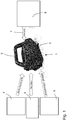
- ein Diagramm mit einer Übersicht über ein Messsystem mit einem Inertial-Messgerät;
- Fig. 2
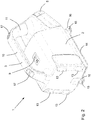
- das Inertial-Messgerät von
Fig. 1 in Perspektivdarstellung; - Fig. 3
- das Inertial-Messgerät in verschiedenen Seitansichten.
- Fig. 4
- eine vergrößerte Seitenansicht des Inertial-Messgeräts von
Fig. 3 ; und - Fig. 5
- eine vergrößerte Untersicht des Inertial-Messgeräts von
Fig. 3 . - In den
Fig. 1 bis 5 wird ein Inertial-Messgerät 1 gezeigt. - Das Inertial-Messgerät 1 weist ein Gehäuse 2 auf, an dem ein Tragegriff 3 ausgebildet ist.
- Im Inneren des Gehäuses 2 ist eine als Nordsucher dienende Inertial-Messeinheit 4, eine wiederaufladbare Batterie 5 und eine Schnittstellenkarte 6 zur Bereitstellung einer drahtlosen Bluetooth-Schnittstelle 7 untergebracht.
- Über die Bluetooth-Schnittstelle 7 ist es möglich, dass das Inertial-Messgerät 1 mit einem als Datenendgerät dienenden Smartphone 8 kommuniziert. Auf dem Smartphone 8 kann eine sogenannte "App" installiert sein, mit deren Hilfe Daten, insbesondere Mess-, Zustands- oder andere Betriebsdaten von dem Inertial-Messgerät 1 angezeigt werden können, die über die Bluetooth-Schnittstelle 7 an das Smartphone 8 übermittelt werden. Ebenso ist es möglich, über das Smartphone 8 Steuerbefehle einzugeben, die dann über die Bluetooth-Schnittstelle 7 an das Inertial-Messgerät 1 übermittelt werden.
- Die Batterie 5 kann als Akkupaket ausgebildet sein, das an einer Stirnseite in das Gehäuses 2 einsteckbar ist. Auf diese Weise kann eine leere Batterie leicht aus dem Gehäuse 2 entnommen und durch eine frisch aufgeladene Batterie 5 ersetzt werden. Dabei bleibt das restliche Gehäuse 2 verschlossen, so dass die empfindlichen Komponenten, insbesondere die Inertial-Messeinheit 4 und die Schnittstellenkarte 6 gut vor Einflüssen von außen geschützt sind.
- Insbesondere kann in dem Gehäuse 2 eine entsprechende Akku- bzw. Batterieaufnahme vorgesehen sein, in die sich die Batterie 5 zuverlässig und sicher einstecken kann. Die Batterieaufnahme kann von den restlichen Komponenten im Inneren des Gehäuses 2, insbesondere der Inertial-Messeinheit 4 und der Schnittstellenkarte 6 separiert sein, um eine Beschädigung dieser Komponenten bei der Handhabung der Batterie 5 zu vermeiden. Zudem kann die Batterieaufnahme gegenüber dem Inneren des Gehäuses 2 abgedichtet sein, um ein Eindringen von Feuchtigkeit zu verhindern.
- An dem Gehäuse 2 ist ein Netzschalter 9 vorgesehen, über den das Inertial-Messgerät 1 ein- und ausgeschaltet werden kann.
- Der Tragegriff 3 ist mit dem restlichen Gehäuse 2 einstückig verbunden. Zweckmäßigerweise können somit das Gehäuse 2 und der Tragegriff 3 als einheitliches Kunststoffbauteil hergestellt werden. Somit kann das Gehäuse 2 einstückig in den Tragegriff 3 übergehen. Der Tragegriff 3 muss somit bei dieser Ausführungsform nicht als eigenständiges Bauelement an dem Gehäuse 2 befestigt werden.
- Der Tragegriff 3 gliedert sich in zwei Griffbereiche: ein erster Griffbereich 10 erstreckt sich im Wesentlichen horizontal. Von dem ersten Griffbereich 10 knickt ein zweiter Griffbereich 11 in einem Winkel ab. Der Bediener kann somit den Tragegriff 3 an beiden Griffbereichen 10, 11 komfortabel greifen.
- Um ein Greifen auch des etwas kürzer ausgebildeten zweiten Griffbereichs 11 zu ermöglichen, ist an dem Gehäuse eine Ausnehmung 12 ausgebildet (
Fig. 4 ). - Gegenüberliegend von dem zweiten Griffbereich 11 und der Ausnehmung 12 sind an der gegenüberliegenden Stirnseite des Gehäuses 2 mehrere Standfüße 13 (im gezeigten Beispiel vier Standfüße 13) ausgebildet. Der Bediener hat damit die Möglichkeit, das Gehäuse 2 an dem zweiten Griffbereich 11 zu ergreifen und auf die Standfüße 13 abzustellen.
- An der Unterseite des Gehäuses 2 erstreckt sich eine horizontale Befestigungsplatte 14. Die Befestigungsplatte 14 ist an dem Gehäuse 2 mit hoher Präzision stabil befestigt und stellt das mechanische Anschlussmittel für das Gehäuse 2 und damit das Inertial-Messgerät 1 dar. An der Befestigungsplatte 14 sind in dem gezeigten Beispiel drei Befestigungsöffnungen 15 vorgesehen, die jeweils in Befestigungslaschen 16 ausgebildet sind, welche sich von der eigentlichen Befestigungsplatte 14 erstrecken.
- An der Oberseite des Tragegriffs 3 sind zwei als Befestigungseinrichtung dienende Ösen 17 vorgesehen. Durch die Ösen 17 kann ein nicht dargestellter Tragriemen durchgefädelt werden, um somit ein Tragen des Inertial-Messgeräts 1 mit Hilfe des Tragriemens zu ermöglichen.
Claims (11)
- Inertial-Messgerät (1), mit- einer Inertial-Messeinheit (4) zum Bestimmen einer Nordrichtung und zum Bestimmen von Lagewinkeln;- einer Batterie (5);- einer drahtlosen Schnittstelle (6); und mit- einem Gehäuse (2), in dem die Inertial-Messeinheit (1), die Batterie (5) und die Schnittstelle (6) untergebracht sind;wobei- an dem Gehäuse (2) ein Tragegriff (3) vorgesehen ist, der als Einhand-Tragegriff ausgebildet ist, zum bestimmungsgemäßen Tragen des Inertial-Messgeräts (1) mit nur einer Hand;- das Gehäuse (2) an seiner Unterseite eine sich horizontal erstreckende Befestigungsplatte (14) aufweist, zum Befestigen des Inertial-Messgeräts an einem Gegenstand;- der Tragegriff (3) an der Oberseite des Gehäuses (2) gegenüber von der Befestigungsplatte (14) angeordnet ist;- das Gehäuse (2) sich in einer Längsrichtung erstreckt;- der Tragegriff (3) sich ebenfalls in der Längsrichtung des Gehäuses (2) erstreckt; und wobei- wenigstens ein Teil des Gehäuses (2) und ein Teil des Tragegriffs (3) einstückig ausgebildet sind.
- Inertial-Messgerät nach Anspruch 1, wobei die Inertial-Messeinheit (4) eine Nordsucher-Einrichtung ist, mit drei Kreiseln und drei Beschleunigungssensoren.
- Inertial-Messgerät nach einem der vorstehenden Ansprüche, wobei die Batterie (5) ein wiederaufladbarer Akku ist.
- Inertial-Messgerät nach einem der vorstehenden Ansprüche, wobei der Acku in dem Gehäuse (2) wechselbar eingesteckt ist.
- Inertial-Messgerät nach einem der vorstehenden Ansprüche, wobei die Schnittstelle (6) eine Bluetooth-Schnittstelle ist.
- Inertial-Messgerät nach einem der vorstehenden Ansprüche, wobei der Tragegriff (3) einen sich im Wesentlichen parallel zu der Befestigungsplatte (14) erstreckenden ersten Griffbereich (10) aufweist.
- Inertial-Messgerät nach einem der vorstehenden Ansprüche, wobei der Tragegriff (3) einen sich in einem Winkel von mehr als 30 Grad, insbesondere mehr als 45 Grad, insbesondere mehr als 60 Grad zu der Befestigungsplatte (14) erstreckenden zweiten Griffbereich (11) aufweist, der sich an den ersten Griffbereich (10) anschließt.
- Inertial-Messgerät nach einem der vorstehenden Ansprüche, wobei an dem Gehäuse (2) und/oder dem Tragegriff (3) eine Befestigungseinrichtung (17) vorgesehen ist, zum Befestigen eines Tragriemens.
- System mit- einem Inertial-Messgerät (1) nach einem der vorstehenden Ansprüche;- einem mobilen Datenendgerät (8); und mit- einem auf dem mobilen Datenendgerät (8) lauffähigen Computerprogramm;wobei- über die Schnittstelle (7) ein Datenaustausch zwischen dem Inertial-Messgerät und dem Datenendgerät möglich ist.
- System nach Anspruch 9, wobei das Datenendgerät (8) eine Anzeigeeinrichtung aufweist, zum Anzeigen der von dem Inertial-Messgerät gemessenen und über die Schnittstelle übertragenen Messergebnisse.
- System nach Anspruch 9 oder 10, wobei das Datenendgerät (8) eine Eingabeeinrichtung aufweist, zum Eingeben von Steuerungsbefehlen, zum Ansteuern des Inertial-Messgeräts.
Applications Claiming Priority (2)
| Application Number | Priority Date | Filing Date | Title |
|---|---|---|---|
| DE102017110205.1A DE102017110205A1 (de) | 2017-05-11 | 2017-05-11 | Inertiales messgerät |
| PCT/EP2018/060966 WO2018206330A1 (de) | 2017-05-11 | 2018-04-27 | Inertiales messgerät zum bestimmen einer nordrichtung |
Publications (2)
| Publication Number | Publication Date |
|---|---|
| EP3622248A1 EP3622248A1 (de) | 2020-03-18 |
| EP3622248B1 true EP3622248B1 (de) | 2021-10-13 |
Family
ID=62063562
Family Applications (1)
| Application Number | Title | Priority Date | Filing Date |
|---|---|---|---|
| EP18720615.6A Active EP3622248B1 (de) | 2017-05-11 | 2018-04-27 | Inertiales messgerät zum bestimmen einer nordrichtung |
Country Status (8)
| Country | Link |
|---|---|
| US (1) | US11841226B2 (de) |
| EP (1) | EP3622248B1 (de) |
| CN (1) | CN110637207B (de) |
| AU (1) | AU2018264892A1 (de) |
| CA (1) | CA3062110A1 (de) |
| CL (1) | CL2019003175A1 (de) |
| DE (1) | DE102017110205A1 (de) |
| WO (1) | WO2018206330A1 (de) |
Family Cites Families (22)
| Publication number | Priority date | Publication date | Assignee | Title |
|---|---|---|---|---|
| DE59505134D1 (de) * | 1995-08-11 | 1999-03-25 | Katadyn Produkte Ag | Kompaktes, tragbares, handbetriebenes kleinfilter zur wasseraufbereitung |
| KR20010063215A (ko) * | 1999-12-22 | 2001-07-09 | 송재인 | 관성 측정 장치의 이상 유무를 판단하기 위한 점검 장치 |
| DE10029536A1 (de) * | 2000-06-15 | 2001-12-20 | Bosch Gmbh Robert | Handwerkzeugmaschine mit zumindest einem Handgriff |
| AT413190B (de) * | 2003-10-16 | 2005-12-15 | Berthold Mag Schroedl | Handschuh, insbesonders arbeits-, untersuchungs- oder operationshandschuh |
| ITMI20050615A1 (it) * | 2005-04-12 | 2006-10-13 | Pamar S P A | Elemento di presa ad incasso per ante scorrevoli e simili |
| US20120059575A1 (en) * | 2010-02-05 | 2012-03-08 | Honeywell International Inc. | Target locator device and methods |
| RU2727040C2 (ru) * | 2011-01-24 | 2020-07-17 | Эббви Байотекнолоджи Лтд. | Автоматические инъекционные устройства, имеющие наформованные поверхности захвата |
| WO2013027377A2 (en) * | 2011-08-23 | 2013-02-28 | Hitachi Koki Co., Ltd. | Power supply device |
| AU2012101210C4 (en) * | 2012-02-22 | 2019-06-27 | Minnovare Pty Ltd | Drill hole orientation apparatus |
| US9372070B1 (en) * | 2012-07-17 | 2016-06-21 | L-3 Communications Corporation | Target locating device and methods |
| DE102012017048B4 (de) * | 2012-08-29 | 2016-09-15 | Khs Gmbh | Behälter- und Transportvorrichtung mit selbstadaptiven Greifelementen sowie Verfahren zum greifenden Transport von Behältern an einer Behandlungs- und Transportvorrichtung |
| US9513107B2 (en) * | 2012-10-05 | 2016-12-06 | Faro Technologies, Inc. | Registration calculation between three-dimensional (3D) scans based on two-dimensional (2D) scan data from a 3D scanner |
| EP2962063B1 (de) * | 2013-02-28 | 2017-03-29 | Fugro N.V. | System und verfahren zur lagemessung |
| GB2516066B (en) * | 2013-07-10 | 2020-07-01 | Atlantic Inertial Systems Ltd | Portable device for determining azimuth |
| EP3046979B1 (de) | 2013-09-22 | 2018-10-24 | Dow Global Technologies LLC | Polyurethan-/acrylhybrid für elastomere wandbeschichtungen |
| CN203879491U (zh) * | 2014-04-28 | 2014-10-15 | 安徽感知安全装备有限公司 | 一种随钻测斜系统的手持仪 |
| US10175358B2 (en) * | 2014-08-04 | 2019-01-08 | Elbit Systems Of America, Llc | Systems and methods for northfinding |
| US20160054355A1 (en) * | 2014-08-20 | 2016-02-25 | Honeywell International Inc. | Compact inertial measurement unit with interface adapter |
| CN106123880A (zh) * | 2016-08-02 | 2016-11-16 | 中良科技集团有限公司 | 一种适应低气压环境的指北针 |
| US10851867B2 (en) * | 2016-08-29 | 2020-12-01 | Verily Life Sciences Llc | Method and system for a feedback controller for a handheld tool |
| DE202017100748U1 (de) * | 2017-02-13 | 2017-02-22 | Angelika Dietz | Aufsätze zur Verbesserung des Klangergebnisses für Streichinstrumente |
| US11199631B2 (en) * | 2017-04-07 | 2021-12-14 | Criterionix, L.L.C. | Apparatus and methods for geo-locating one or more objects |
-
2017
- 2017-05-11 DE DE102017110205.1A patent/DE102017110205A1/de not_active Withdrawn
-
2018
- 2018-04-27 EP EP18720615.6A patent/EP3622248B1/de active Active
- 2018-04-27 AU AU2018264892A patent/AU2018264892A1/en not_active Withdrawn
- 2018-04-27 CN CN201880030328.4A patent/CN110637207B/zh active Active
- 2018-04-27 CA CA3062110A patent/CA3062110A1/en not_active Abandoned
- 2018-04-27 US US16/612,377 patent/US11841226B2/en active Active
- 2018-04-27 WO PCT/EP2018/060966 patent/WO2018206330A1/de not_active Ceased
-
2019
- 2019-11-05 CL CL2019003175A patent/CL2019003175A1/es unknown
Also Published As
| Publication number | Publication date |
|---|---|
| CL2019003175A1 (es) | 2020-01-31 |
| EP3622248A1 (de) | 2020-03-18 |
| AU2018264892A1 (en) | 2019-12-12 |
| CN110637207B (zh) | 2023-07-18 |
| US20200096335A1 (en) | 2020-03-26 |
| WO2018206330A1 (de) | 2018-11-15 |
| CA3062110A1 (en) | 2019-11-22 |
| DE102017110205A1 (de) | 2018-11-15 |
| US11841226B2 (en) | 2023-12-12 |
| CN110637207A (zh) | 2019-12-31 |
Similar Documents
| Publication | Publication Date | Title |
|---|---|---|
| DE2920194C2 (de) | ||
| DE69904759T2 (de) | Orientierungswinkeldetektor | |
| DE102009018070A1 (de) | Mobile Arbeitsmaschine mit einer Positionsregeleinrichtung eines Arbeitsarms und Verfahren zur Positionregelung eines Arbeitsarms einer mobilen Arbeitsmaschine | |
| DE2849633C2 (de) | Vorrichtung zum Messen von Azimut und Neigung eines Bohrlochs | |
| DE102014115383A1 (de) | Handgerät sowie mobile Einrichtung zur Röntgenfluoreszenzanalyse | |
| DE602004009298T2 (de) | System zur verwaltung von bohrlochdaten | |
| DE102016102753A1 (de) | Handwerkzeug mit Lagebestimmung und Verfahren zur Lagebestimmung eines Handwerkzeuges | |
| EP1108980A2 (de) | Ergonomisch gestaltete, störsignalreduzierende Lagemesssonde zum gegenseitigen Ausrichten von Körpern | |
| DE19800901B4 (de) | Lagemeßsonde zum gegenseitigen Ausrichten von Körpern | |
| EP3622248B1 (de) | Inertiales messgerät zum bestimmen einer nordrichtung | |
| DE3331448A1 (de) | Verfahren und vorrichtung zum messen eines bohrloches | |
| DE102019120547A1 (de) | Vorrichtung und Verfahren zum Ausrichten eines Bohrgeräts | |
| DE3408137C2 (de) | ||
| EP4073601B1 (de) | Verarbeitungsvorrichtung zum steuern, messen und regeln | |
| DE102015107254A1 (de) | Stoßfestes integriertes mehrachsiges Gyroskop | |
| DE102016103166A1 (de) | Sensorsystem und Verfahren zur räumlichen Verlaufsmessung eines Bohrlochs | |
| EP1004003B1 (de) | Stossschutz für lagemess-sonden | |
| WO2022106520A1 (de) | Haltevorrichtung zum ortsfesten haltern eines head-mounted-devices, anordnung aus einem head-mounted-device und einer gyroskopeinrichtung, head-mounted-device, augmented-reality-brille, set mit einem solchen head-mounted-device und einer haltevorrichtung hierfür, fahrzeug, sowie verfahren zum betreiben eines solchen head-mounted-devices | |
| DE2158244C3 (de) | Verfahren und Vorrichtung zum Zielhalten für ein auf einer stabilisierten Plattform eines Fahrzeugs angeordnetes Sichtgerät | |
| EP1044352A1 (de) | Drehratenmesseinrichtung für rotierende flugkörper | |
| DE102024118279B3 (de) | Rotationstisch mit verkippbarer Sensoraufnahme | |
| DE952611C (de) | Verfahren und Einrichtung zur Messung der Abweichung von Bohrloechern von der Lotrechten in Abhaengigkeit von der Tiefe | |
| EP4397822A1 (de) | Betonagesystem mit positionsbestimmung für innenrüttler | |
| DE102004057959A1 (de) | Vorrichtung zur Vermittlung von Informationen an einen Benutzer | |
| WO2007003161A9 (de) | Schockisolationssystem für eine inertialsensoranordnung |
Legal Events
| Date | Code | Title | Description |
|---|---|---|---|
| STAA | Information on the status of an ep patent application or granted ep patent |
Free format text: STATUS: UNKNOWN |
|
| STAA | Information on the status of an ep patent application or granted ep patent |
Free format text: STATUS: THE INTERNATIONAL PUBLICATION HAS BEEN MADE |
|
| PUAI | Public reference made under article 153(3) epc to a published international application that has entered the european phase |
Free format text: ORIGINAL CODE: 0009012 |
|
| STAA | Information on the status of an ep patent application or granted ep patent |
Free format text: STATUS: REQUEST FOR EXAMINATION WAS MADE |
|
| 17P | Request for examination filed |
Effective date: 20191024 |
|
| AK | Designated contracting states |
Kind code of ref document: A1 Designated state(s): AL AT BE BG CH CY CZ DE DK EE ES FI FR GB GR HR HU IE IS IT LI LT LU LV MC MK MT NL NO PL PT RO RS SE SI SK SM TR |
|
| AX | Request for extension of the european patent |
Extension state: BA ME |
|
| RIN1 | Information on inventor provided before grant (corrected) |
Inventor name: KUEHNE, CLAUS Inventor name: DAHLHOFF, ANDREA Inventor name: SPANNAGEL, CHRISTIAN |
|
| DAV | Request for validation of the european patent (deleted) | ||
| DAX | Request for extension of the european patent (deleted) | ||
| GRAP | Despatch of communication of intention to grant a patent |
Free format text: ORIGINAL CODE: EPIDOSNIGR1 |
|
| STAA | Information on the status of an ep patent application or granted ep patent |
Free format text: STATUS: GRANT OF PATENT IS INTENDED |
|
| INTG | Intention to grant announced |
Effective date: 20210510 |
|
| GRAS | Grant fee paid |
Free format text: ORIGINAL CODE: EPIDOSNIGR3 |
|
| GRAA | (expected) grant |
Free format text: ORIGINAL CODE: 0009210 |
|
| STAA | Information on the status of an ep patent application or granted ep patent |
Free format text: STATUS: THE PATENT HAS BEEN GRANTED |
|
| AK | Designated contracting states |
Kind code of ref document: B1 Designated state(s): AL AT BE BG CH CY CZ DE DK EE ES FI FR GB GR HR HU IE IS IT LI LT LU LV MC MK MT NL NO PL PT RO RS SE SI SK SM TR |
|
| REG | Reference to a national code |
Ref country code: GB Ref legal event code: FG4D Free format text: NOT ENGLISH |
|
| REG | Reference to a national code |
Ref country code: CH Ref legal event code: EP |
|
| REG | Reference to a national code |
Ref country code: DE Ref legal event code: R096 Ref document number: 502018007437 Country of ref document: DE |
|
| REG | Reference to a national code |
Ref country code: IE Ref legal event code: FG4D Free format text: LANGUAGE OF EP DOCUMENT: GERMAN |
|
| REG | Reference to a national code |
Ref country code: AT Ref legal event code: REF Ref document number: 1438486 Country of ref document: AT Kind code of ref document: T Effective date: 20211115 |
|
| REG | Reference to a national code |
Ref country code: SE Ref legal event code: TRGR |
|
| REG | Reference to a national code |
Ref country code: LT Ref legal event code: MG9D |
|
| REG | Reference to a national code |
Ref country code: NL Ref legal event code: MP Effective date: 20211013 |
|
| REG | Reference to a national code |
Ref country code: NO Ref legal event code: T2 Effective date: 20211013 |
|
| PG25 | Lapsed in a contracting state [announced via postgrant information from national office to epo] |
Ref country code: RS Free format text: LAPSE BECAUSE OF FAILURE TO SUBMIT A TRANSLATION OF THE DESCRIPTION OR TO PAY THE FEE WITHIN THE PRESCRIBED TIME-LIMIT Effective date: 20211013 Ref country code: LT Free format text: LAPSE BECAUSE OF FAILURE TO SUBMIT A TRANSLATION OF THE DESCRIPTION OR TO PAY THE FEE WITHIN THE PRESCRIBED TIME-LIMIT Effective date: 20211013 Ref country code: FI Free format text: LAPSE BECAUSE OF FAILURE TO SUBMIT A TRANSLATION OF THE DESCRIPTION OR TO PAY THE FEE WITHIN THE PRESCRIBED TIME-LIMIT Effective date: 20211013 Ref country code: BG Free format text: LAPSE BECAUSE OF FAILURE TO SUBMIT A TRANSLATION OF THE DESCRIPTION OR TO PAY THE FEE WITHIN THE PRESCRIBED TIME-LIMIT Effective date: 20220113 |
|
| PG25 | Lapsed in a contracting state [announced via postgrant information from national office to epo] |
Ref country code: IS Free format text: LAPSE BECAUSE OF FAILURE TO SUBMIT A TRANSLATION OF THE DESCRIPTION OR TO PAY THE FEE WITHIN THE PRESCRIBED TIME-LIMIT Effective date: 20220213 Ref country code: PT Free format text: LAPSE BECAUSE OF FAILURE TO SUBMIT A TRANSLATION OF THE DESCRIPTION OR TO PAY THE FEE WITHIN THE PRESCRIBED TIME-LIMIT Effective date: 20220214 Ref country code: PL Free format text: LAPSE BECAUSE OF FAILURE TO SUBMIT A TRANSLATION OF THE DESCRIPTION OR TO PAY THE FEE WITHIN THE PRESCRIBED TIME-LIMIT Effective date: 20211013 Ref country code: NL Free format text: LAPSE BECAUSE OF FAILURE TO SUBMIT A TRANSLATION OF THE DESCRIPTION OR TO PAY THE FEE WITHIN THE PRESCRIBED TIME-LIMIT Effective date: 20211013 Ref country code: LV Free format text: LAPSE BECAUSE OF FAILURE TO SUBMIT A TRANSLATION OF THE DESCRIPTION OR TO PAY THE FEE WITHIN THE PRESCRIBED TIME-LIMIT Effective date: 20211013 Ref country code: HR Free format text: LAPSE BECAUSE OF FAILURE TO SUBMIT A TRANSLATION OF THE DESCRIPTION OR TO PAY THE FEE WITHIN THE PRESCRIBED TIME-LIMIT Effective date: 20211013 Ref country code: GR Free format text: LAPSE BECAUSE OF FAILURE TO SUBMIT A TRANSLATION OF THE DESCRIPTION OR TO PAY THE FEE WITHIN THE PRESCRIBED TIME-LIMIT Effective date: 20220114 Ref country code: ES Free format text: LAPSE BECAUSE OF FAILURE TO SUBMIT A TRANSLATION OF THE DESCRIPTION OR TO PAY THE FEE WITHIN THE PRESCRIBED TIME-LIMIT Effective date: 20211013 |
|
| REG | Reference to a national code |
Ref country code: DE Ref legal event code: R097 Ref document number: 502018007437 Country of ref document: DE |
|
| PG25 | Lapsed in a contracting state [announced via postgrant information from national office to epo] |
Ref country code: SM Free format text: LAPSE BECAUSE OF FAILURE TO SUBMIT A TRANSLATION OF THE DESCRIPTION OR TO PAY THE FEE WITHIN THE PRESCRIBED TIME-LIMIT Effective date: 20211013 Ref country code: SK Free format text: LAPSE BECAUSE OF FAILURE TO SUBMIT A TRANSLATION OF THE DESCRIPTION OR TO PAY THE FEE WITHIN THE PRESCRIBED TIME-LIMIT Effective date: 20211013 Ref country code: RO Free format text: LAPSE BECAUSE OF FAILURE TO SUBMIT A TRANSLATION OF THE DESCRIPTION OR TO PAY THE FEE WITHIN THE PRESCRIBED TIME-LIMIT Effective date: 20211013 Ref country code: EE Free format text: LAPSE BECAUSE OF FAILURE TO SUBMIT A TRANSLATION OF THE DESCRIPTION OR TO PAY THE FEE WITHIN THE PRESCRIBED TIME-LIMIT Effective date: 20211013 Ref country code: DK Free format text: LAPSE BECAUSE OF FAILURE TO SUBMIT A TRANSLATION OF THE DESCRIPTION OR TO PAY THE FEE WITHIN THE PRESCRIBED TIME-LIMIT Effective date: 20211013 Ref country code: CZ Free format text: LAPSE BECAUSE OF FAILURE TO SUBMIT A TRANSLATION OF THE DESCRIPTION OR TO PAY THE FEE WITHIN THE PRESCRIBED TIME-LIMIT Effective date: 20211013 |
|
| PLBE | No opposition filed within time limit |
Free format text: ORIGINAL CODE: 0009261 |
|
| STAA | Information on the status of an ep patent application or granted ep patent |
Free format text: STATUS: NO OPPOSITION FILED WITHIN TIME LIMIT |
|
| 26N | No opposition filed |
Effective date: 20220714 |
|
| PG25 | Lapsed in a contracting state [announced via postgrant information from national office to epo] |
Ref country code: AL Free format text: LAPSE BECAUSE OF FAILURE TO SUBMIT A TRANSLATION OF THE DESCRIPTION OR TO PAY THE FEE WITHIN THE PRESCRIBED TIME-LIMIT Effective date: 20211013 |
|
| PG25 | Lapsed in a contracting state [announced via postgrant information from national office to epo] |
Ref country code: SI Free format text: LAPSE BECAUSE OF FAILURE TO SUBMIT A TRANSLATION OF THE DESCRIPTION OR TO PAY THE FEE WITHIN THE PRESCRIBED TIME-LIMIT Effective date: 20211013 |
|
| REG | Reference to a national code |
Ref country code: CH Ref legal event code: PL |
|
| GBPC | Gb: european patent ceased through non-payment of renewal fee |
Effective date: 20220427 |
|
| REG | Reference to a national code |
Ref country code: BE Ref legal event code: MM Effective date: 20220430 |
|
| PG25 | Lapsed in a contracting state [announced via postgrant information from national office to epo] |
Ref country code: MC Free format text: LAPSE BECAUSE OF FAILURE TO SUBMIT A TRANSLATION OF THE DESCRIPTION OR TO PAY THE FEE WITHIN THE PRESCRIBED TIME-LIMIT Effective date: 20211013 Ref country code: LU Free format text: LAPSE BECAUSE OF NON-PAYMENT OF DUE FEES Effective date: 20220427 Ref country code: LI Free format text: LAPSE BECAUSE OF NON-PAYMENT OF DUE FEES Effective date: 20220430 Ref country code: GB Free format text: LAPSE BECAUSE OF NON-PAYMENT OF DUE FEES Effective date: 20220427 Ref country code: FR Free format text: LAPSE BECAUSE OF NON-PAYMENT OF DUE FEES Effective date: 20220430 Ref country code: CH Free format text: LAPSE BECAUSE OF NON-PAYMENT OF DUE FEES Effective date: 20220430 |
|
| PG25 | Lapsed in a contracting state [announced via postgrant information from national office to epo] |
Ref country code: BE Free format text: LAPSE BECAUSE OF NON-PAYMENT OF DUE FEES Effective date: 20220430 |
|
| PG25 | Lapsed in a contracting state [announced via postgrant information from national office to epo] |
Ref country code: IE Free format text: LAPSE BECAUSE OF NON-PAYMENT OF DUE FEES Effective date: 20220427 |
|
| P01 | Opt-out of the competence of the unified patent court (upc) registered |
Effective date: 20230512 |
|
| PG25 | Lapsed in a contracting state [announced via postgrant information from national office to epo] |
Ref country code: MK Free format text: LAPSE BECAUSE OF FAILURE TO SUBMIT A TRANSLATION OF THE DESCRIPTION OR TO PAY THE FEE WITHIN THE PRESCRIBED TIME-LIMIT Effective date: 20211013 Ref country code: CY Free format text: LAPSE BECAUSE OF FAILURE TO SUBMIT A TRANSLATION OF THE DESCRIPTION OR TO PAY THE FEE WITHIN THE PRESCRIBED TIME-LIMIT Effective date: 20211013 |
|
| PG25 | Lapsed in a contracting state [announced via postgrant information from national office to epo] |
Ref country code: HU Free format text: LAPSE BECAUSE OF FAILURE TO SUBMIT A TRANSLATION OF THE DESCRIPTION OR TO PAY THE FEE WITHIN THE PRESCRIBED TIME-LIMIT; INVALID AB INITIO Effective date: 20180427 |
|
| REG | Reference to a national code |
Ref country code: AT Ref legal event code: MM01 Ref document number: 1438486 Country of ref document: AT Kind code of ref document: T Effective date: 20230427 |
|
| PG25 | Lapsed in a contracting state [announced via postgrant information from national office to epo] |
Ref country code: AT Free format text: LAPSE BECAUSE OF NON-PAYMENT OF DUE FEES Effective date: 20230427 |
|
| PG25 | Lapsed in a contracting state [announced via postgrant information from national office to epo] |
Ref country code: AT Free format text: LAPSE BECAUSE OF NON-PAYMENT OF DUE FEES Effective date: 20230427 |
|
| PG25 | Lapsed in a contracting state [announced via postgrant information from national office to epo] |
Ref country code: MT Free format text: LAPSE BECAUSE OF FAILURE TO SUBMIT A TRANSLATION OF THE DESCRIPTION OR TO PAY THE FEE WITHIN THE PRESCRIBED TIME-LIMIT Effective date: 20211013 |
|
| PGFP | Annual fee paid to national office [announced via postgrant information from national office to epo] |
Ref country code: DE Payment date: 20250415 Year of fee payment: 8 |
|
| PGFP | Annual fee paid to national office [announced via postgrant information from national office to epo] |
Ref country code: NO Payment date: 20250422 Year of fee payment: 8 |
|
| PGFP | Annual fee paid to national office [announced via postgrant information from national office to epo] |
Ref country code: IT Payment date: 20250430 Year of fee payment: 8 |
|
| PGFP | Annual fee paid to national office [announced via postgrant information from national office to epo] |
Ref country code: SE Payment date: 20250423 Year of fee payment: 8 |
|
| PG25 | Lapsed in a contracting state [announced via postgrant information from national office to epo] |
Ref country code: TR Free format text: LAPSE BECAUSE OF FAILURE TO SUBMIT A TRANSLATION OF THE DESCRIPTION OR TO PAY THE FEE WITHIN THE PRESCRIBED TIME-LIMIT Effective date: 20211013 |
|
| PGFP | Annual fee paid to national office [announced via postgrant information from national office to epo] |
Ref country code: AT Payment date: 20260410 Year of fee payment: 5 |