EP3620670A1 - Anchor rod assembly with pumping head - Google Patents
Anchor rod assembly with pumping head Download PDFInfo
- Publication number
- EP3620670A1 EP3620670A1 EP18192405.1A EP18192405A EP3620670A1 EP 3620670 A1 EP3620670 A1 EP 3620670A1 EP 18192405 A EP18192405 A EP 18192405A EP 3620670 A1 EP3620670 A1 EP 3620670A1
- Authority
- EP
- European Patent Office
- Prior art keywords
- anchor rod
- additional element
- rod assembly
- sleeve
- section
- Prior art date
- Legal status (The legal status is an assumption and is not a legal conclusion. Google has not performed a legal analysis and makes no representation as to the accuracy of the status listed.)
- Withdrawn
Links
- 238000005086 pumping Methods 0.000 title 1
- 239000004570 mortar (masonry) Substances 0.000 claims abstract description 48
- 229920003002 synthetic resin Polymers 0.000 claims abstract description 22
- 239000000057 synthetic resin Substances 0.000 claims abstract description 22
- 239000000463 material Substances 0.000 claims description 30
- 230000002093 peripheral effect Effects 0.000 claims description 11
- 239000004033 plastic Substances 0.000 claims description 9
- 229920003023 plastic Polymers 0.000 claims description 9
- 230000004323 axial length Effects 0.000 claims description 5
- 239000002775 capsule Substances 0.000 description 9
- 238000002347 injection Methods 0.000 description 9
- 239000007924 injection Substances 0.000 description 9
- 239000002131 composite material Substances 0.000 description 8
- 239000004952 Polyamide Substances 0.000 description 5
- 229920002647 polyamide Polymers 0.000 description 5
- 230000003068 static effect Effects 0.000 description 5
- 238000004873 anchoring Methods 0.000 description 4
- 239000003822 epoxy resin Substances 0.000 description 4
- 229920000647 polyepoxide Polymers 0.000 description 4
- 239000004567 concrete Substances 0.000 description 3
- 239000006260 foam Substances 0.000 description 3
- 239000011521 glass Substances 0.000 description 3
- 230000001070 adhesive effect Effects 0.000 description 2
- 235000019589 hardness Nutrition 0.000 description 2
- 238000000034 method Methods 0.000 description 2
- 239000000203 mixture Substances 0.000 description 2
- 230000032258 transport Effects 0.000 description 2
- 241000169624 Casearia sylvestris Species 0.000 description 1
- 239000004593 Epoxy Substances 0.000 description 1
- 229910000831 Steel Inorganic materials 0.000 description 1
- 230000003213 activating effect Effects 0.000 description 1
- 230000004913 activation Effects 0.000 description 1
- 230000001154 acute effect Effects 0.000 description 1
- 239000000853 adhesive Substances 0.000 description 1
- 230000002411 adverse Effects 0.000 description 1
- 230000015572 biosynthetic process Effects 0.000 description 1
- 238000004140 cleaning Methods 0.000 description 1
- 150000001875 compounds Chemical class 0.000 description 1
- 230000000694 effects Effects 0.000 description 1
- 238000000605 extraction Methods 0.000 description 1
- 229920002457 flexible plastic Polymers 0.000 description 1
- 239000011888 foil Substances 0.000 description 1
- 238000009472 formulation Methods 0.000 description 1
- LNEPOXFFQSENCJ-UHFFFAOYSA-N haloperidol Chemical compound C1CC(O)(C=2C=CC(Cl)=CC=2)CCN1CCCC(=O)C1=CC=C(F)C=C1 LNEPOXFFQSENCJ-UHFFFAOYSA-N 0.000 description 1
- 238000001746 injection moulding Methods 0.000 description 1
- 238000003780 insertion Methods 0.000 description 1
- 230000037431 insertion Effects 0.000 description 1
- 239000007788 liquid Substances 0.000 description 1
- 239000002184 metal Substances 0.000 description 1
- 235000011837 pasties Nutrition 0.000 description 1
- 239000002985 plastic film Substances 0.000 description 1
- 229920006255 plastic film Polymers 0.000 description 1
- 229920000642 polymer Polymers 0.000 description 1
- 230000008569 process Effects 0.000 description 1
- 150000003254 radicals Chemical class 0.000 description 1
- 239000010959 steel Substances 0.000 description 1
- 230000007704 transition Effects 0.000 description 1
- 230000001960 triggered effect Effects 0.000 description 1
Images


Classifications
-
- F—MECHANICAL ENGINEERING; LIGHTING; HEATING; WEAPONS; BLASTING
- F16—ENGINEERING ELEMENTS AND UNITS; GENERAL MEASURES FOR PRODUCING AND MAINTAINING EFFECTIVE FUNCTIONING OF MACHINES OR INSTALLATIONS; THERMAL INSULATION IN GENERAL
- F16B—DEVICES FOR FASTENING OR SECURING CONSTRUCTIONAL ELEMENTS OR MACHINE PARTS TOGETHER, e.g. NAILS, BOLTS, CIRCLIPS, CLAMPS, CLIPS OR WEDGES; JOINTS OR JOINTING
- F16B13/00—Dowels or other devices fastened in walls or the like by inserting them in holes made therein for that purpose
- F16B13/14—Non-metallic plugs or sleeves; Use of liquid, loose solid or kneadable material therefor
- F16B13/141—Fixing plugs in holes by the use of settable material
- F16B2013/148—Means for inhibiting adhesion between dowel or anchor bolt parts and the surrounding grouting composition
Definitions
- the invention relates to an anchor rod assembly for fastening in synthetic resin mortar.
- Anchor rods are known from the prior art which have a fastening section which has at least one conical section. Anchor rods of this type are usually used together with free-radically hardening mortars, and very good load values can be obtained even in cracked and / or unpurified boreholes.
- the free radical curing materials, the polyadditive curing materials and the components of the composite anchor capsule are also generally referred to herein as synthetic resin mortars.
- the components of the mortar compound are mixed intimately.
- this is controlled by the static mixer.
- the armature rod rotates around the longitudinal axis (in the mounting hole) for the necessary mixing.
- the anchor rod also has the task of crushing the glass ampoules or the foil bags. This must be done to such an extent that the holding values are not adversely affected by larger remnants of the glass ampoules or the film adhering to the borehole wall.
- Such an anchor rod is approximately from the EP 0856 669 A1 known.
- polyadditive hardening mortars such as epoxy resins
- these mortar properties are a significantly higher adhesive strength of the mortar and also significantly better tensile / compressive strength. This means that the mortar sleeve surrounding the anchor rod cannot be broken open when the anchor rod is fastened in polyadditive hardening mortar, but this is necessary for anchoring the anchor rod.
- the object of the invention is to provide an anchor rod which, regardless of the mortar material, can be used for injection systems and for composite anchor capsules.
- the invention relates to an anchor rod assembly for fastening in synthetic resin mortar, with an anchor rod having a shaft section, a special one Fastening section and a head part, wherein the fastening section, which is provided between the shaft section and the head part, is at least partially surrounded by a sleeve-like additional element, and wherein the head part has a cutting edge at its free end.
- the head part also has an axial end, which is also referred to as the free end or the insertion end of the anchor rod assembly.
- the special fastening section preferably has cone-like sections.
- the cone-like sections support the post-expansion behavior of the composite anchor, for example in cracked concrete with an opening receiving hole, and lead to a better introduction of the expansion pressure over the length of the anchoring area.
- the cutting edge provided at the free end of the head part serves to break open and comminute the composite anchor capsule and to mix both its content and the content with the comminuted capsule.
- the cutting edge is not required to use the anchor rod with injection systems. The cutting edge does not affect the function of the anchor rod in any way.
- the cutting edge is expediently formed by a wedge-shaped beveling of the head part.
- the peripheral surface of the head part is preferably profiled. This supports the mixing of the contents of the capsule and the mixing of the comminuted capsule into the mortar when using anchoring capsules. Furthermore, the transport of the mixed mass is supported when screwing the anchor rod away from the bottom of the borehole.
- the profile of the peripheral surface of the head part supports the mixing of the mortar mass when the anchor rod is introduced into the borehole filled with the mortar mass.
- the profiling of the peripheral surface of the head part is a thread-like profile, the direction of rotation of which coincides with the direction of rotation of the coarse-thread profiled fastening section.
- the thread-like profile of the head section transports and mixes the mortar mass like in a screw conveyor.
- the profiling of the peripheral surface of the head part is knurling in the form of essentially axially extending grooves which extend from the free front end to the fastening section.
- the surface of the anchoring area preferably has non-adhesive properties compared to the synthetic resin mortar. This is achieved according to the invention by a sleeve-like additional element.
- a basic idea of the invention is that the anchor rod is not only embedded with its fastening section in the synthetic resin mortar, but that at least in regions the sleeve-like additional element comes into direct contact with the synthetic resin mortar.
- the additional element surrounds the fastening section over its entire circumference at least in regions, which ensures that the anchor rod assembly is embedded in the synthetic resin mortar at least in a certain cross-sectional plane exclusively via the additional element.
- the sleeve-shaped additional element is connected to the anchor rod in such a way that it can be easily separated from the anchor rod.
- the sleeve-like additional element consists of at least two different materials with different hardness, such as plastic or rigid foam or a combination of both.
- the different materials which have different hardnesses, form a support area and a tear area, the support area being formed from the harder material.
- the tear area of the sleeve-like additional element at least in a cross-sectional plane through several radial Web sections are formed in the additional element, which extend from the inside of the additional element to the outside thereof.
- the sleeve-like additional element essentially has an annular cross section. These web sections, which extend from radially inside to radially outside, ensure that there are no continuous sections of the support region in the circumferential direction. Accordingly, the radial web sections formed from the softer material ensure that the additional element tears under a predefined load (predetermined breaking points), which is less than if only one and the same (hard) material were used.
- a circular section element of the support area is provided between two adjacent web sections. Accordingly, part of the support area alternates with part of the tear area in a cross-sectional plane, so that uniform support of the additional element is ensured. In this cross-sectional plane, the additional element therefore only consists of the support area and the tear area, that is to say the circular sections and the radial web sections.
- the tear area and / or the support area can be formed in a plurality of cross-sectional planes of the additional element, in particular wherein the tear area and / or the support area extend or extend over the entire axial length of the additional element, preferably continuously. In addition, this ensures that the additional element can tear when viewed over its entire axial length when a predetermined force acts on the additional element.
- Another aspect of the invention provides that the additional element has been injection molded onto the anchor rod.
- the anchor rod assembly can be produced inexpensively, since the additional element surrounding the fastening section can be connected to the anchor rod in a simple manner.
- the additional element can have at least one plastic material.
- This plastic material can be a polyamide, for example, which forms the support area of the additional element.
- the further material which forms the tear area can likewise consist of a plastic material which has a correspondingly lower tear strength than polyamide, if polyamide is used as that Support area material is used.
- rigid foam or a flexible plastic can also be used.
- the additional element is a two-component injection molded part. This ensures in a simple manner that the additional element formed from two different materials can be attached to the anchor rod in a single method step.
- the anchor rod can be formed from a metal, in particular from steel. This ensures that the anchor rod can absorb or transmit the loads that occur.
- FIG. 1 An anchor rod assembly 10 is shown that can be used in an epoxy resin mortar.
- the anchor rod assembly 10 has an anchor rod 12, which comprises a shaft section 14, a fastening section 16 and a mixing section 20 designed as a head part.
- the fastening section 16 has a plurality of conical sections 18, which are arranged one after the other in series in the axial direction and each extend in the direction of the shaft section 14 with the narrower end.
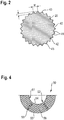
- the mixing section 20 also has an axial end 22, which in the embodiment shown is essentially circular in cross section.
- the axial end 22 is also referred to as the free end of the anchor rod assembly 10.
- the anchor rod assembly 10 comprises a sleeve-like additional element 50, which is shown partially cut in the embodiment shown.
- the additional element 50 surrounds the entire fastening section 16.
- the additional element 50 extends in the axial direction from the end of the fastening section 16 facing away from the shaft section 14 to the shaft section 14, the additional element 50 at the transition between the fastening section 16 and the shaft section 14 rests and is fastened with the fastening section 16.
- the additional element 50 is formed from two plastic materials, for example polyamide and a softer plastic material or foam. Accordingly, the additional element 50 may have been injection molded onto the anchor rod 12 in a two-component injection molding process, in particular on the shaft section 14, in order to form the anchor rod assembly 10.
- the tear area 52 is formed by radial web sections 53, two of which are shown.
- the radial web sections 53 extend from a radially inner inner edge 54 of the additional element 50 radially outward to a radially outer outer edge 55 of the additional element 50. Accordingly, the radial web sections 53 extend in the radial direction over the entire extent of the additional element 50.
- a circular section element 56 is provided, which is formed from the harder plastic material, for example from polyamide.
- the circular section elements 56 each comprise an angular range of approximately 60 ° in the embodiment shown.
- the radial web sections 53 and the circular section elements 56 are each arranged alternately in the circumferential direction, so that a homogeneous support area 51 and a homogeneous tear area 52 are formed in the cross-sectional plane.
- a plurality of or less radial web sections 53 can also be provided, so that correspondingly more or fewer circular section elements 56 are provided, which then each encompass a smaller or larger angular range.
- the additional element 50 preferably has a plurality of such cross-sectional planes, as shown in FIG Figure 4 are shown. Accordingly, the additional element 50 also has essentially homogeneous support and tear properties over its axial length.
- the radial web sections 53 and the circular section elements 56 extend continuously in the axial direction of the additional element 50. Accordingly, the additional element 50 tears over its entire axial length, provided that the predefined force has been reached.
- the web sections 56 generally form one or more predetermined breaking point (s) of the additional element 50.
- the predetermined breaking point or the predetermined breaking points can be formed in the additional element 50 and the required force at which the additional element 50 tears can be set via the support area 51 and the tear area 52 and the corresponding material properties of the materials used.
- the additional element 50 separates in the region of the radial web sections 53 or tears, as a result of which the anchor rod 12 enclosed by the additional element 50, in particular its fastening section 16, can engage in the torn parts of the additional element 50, so that the anchor rod 12 engages in the torn ones Parts of the additional element 50 can be anchored with the mortar sleeve adhering to it.
- the anchor rod 12 it is possible for the anchor rod 12 to find a hold in a borehole filled with synthetic resin mortar even if this would not otherwise be possible due to poor borehole cleaning and / or difficult application conditions.
- a force can be exerted on the anchor rod 12, in particular via a threaded section, not shown here, due to which the additional element 50 tears.
- the threaded section can adjoin the shaft section 14 or the shaft section 14 merges into the threaded section.
- the foremost section of the anchor rod 12 facing the bottom of the borehole is designed as a head part 20, at the free front end 22 of which a cutting edge 24 is provided which extends approximately perpendicular to the axis A of the anchor rod 12.
- the head part 20 is provided in the front area with a bevel 28 which extends up to the peripheral surface 30 of the head part 20.
- the illustrated embodiment variants of the invention consist in the formation of conveying devices 26, which are provided in the largest diameter cylindrical region 34 of the head part 20.
- the conveying devices 26 consist of a knurling of the peripheral surface 30.
- the knurling forms approximately axially extending grooves 40, which extend from the free front end 22 equipped with the cutting edge 24 to the conical section 32 of the head part 20.
- the grooves 40 have flanks 41 which extend obliquely from the groove base 42 to the peripheral surface 30. There they meet at an acute angle on the flanks 41 of adjacent grooves 40 and form a sharp edge 43 on the circumferential surface 30.
- the circumferential surface 30 provided with toothed strips in this way supports the comminution of the container, for example a plastic film, when the anchor rod rotates in the receiving bore .
- the depth t of the grooves is from about 0.5 mm to about 2.5 mm.
- the greatest width w of the grooves is about 1 mm to about 3 mm.
- the conveyor devices 26 consist of a thread-like profiling 44, which is provided in the peripheral surface 30 of the cylindrical region 34 of the head part 20.
- the thread-like profile 44 has the same direction of rotation as the coarse thread 18 of the fastening section 16.
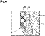
- the borehole 60 is provided in a component 61 made of concrete or the like, the borehole 60 being torn in the concrete, for example, which is why the borehole 60 has been filled with a synthetic resin mortar 62 into which the anchor rod assembly 10 has been inserted.
- the synthetic resin mortar 62 forms a mortar sleeve 63 which has formed around the additional element 50 and is connected to it.
- the additional element 50 is formed in particular from a material or materials with which the synthetic resin mortar 62 connects as if the synthetic resin mortar 62 and that were Additional element 50 a single material.
- the synthetic resin mortar 62 and the additional element 50 therefore form an integral or homogeneous bond.
- the anchor rod assembly 10 Since the synthetic resin mortar 62 has hardened, the anchor rod assembly 10, in particular the additional element 50, is firmly accommodated in the synthetic resin mortar 62.
- the anchor rod 12 can then build up an expansion effect which contributes to increasing the load-bearing capacity.
- the anchor rod assembly 10 fasten the anchor rod 12 in a borehole 60 filled with synthetic resin mortar, in particular with epoxy resin mortar, in particular even if the borehole 60 has not been cleaned beforehand.
- the additional element 50 is designed as a cap-like or sleeve-like element, which can also be referred to as a dowel, in particular a drawing dowel.
- the anchor rod explained using the example of two design variants ensures reliable comminution of the container in which the synthetic resin mortar composition and its components are contained. Due to the geometric design of the mixing section of the anchor rod according to the invention, the individual components of two- or multi-component mortar systems are intimately mixed. The mixed mortar is distributed evenly over the anchor area of the anchor rod.
- the geometry of the anchor rod according to the invention also supports the post-expansion behavior of the anchor rod, as a result of which it ensures sufficiently high holding values even in cracked subsoil when the crack opens.
Abstract
Eine Ankerstangenbaugruppe für die Befestigung in Kunstharz-Mörtel ist beschrieben, mit einer Ankerstange, die einen Schaftabschnitt, einen Befestigungsabschnitt und ein Kopfteil, das eine Schneide aufweist, und mit einem hülsenartigen Zusatzelement, das zumindest den Befestigungsabschnitt bereichsweise umgibt.An anchor rod assembly for fastening in synthetic resin mortar is described, with an anchor rod that has a shaft section, a fastening section and a head part that has a cutting edge, and with a sleeve-like additional element that at least partially surrounds the fastening section.
Description
Die Erfindung betrifft eine Ankerstangenbaugruppe für die Befestigung in Kunstharz-Mörtel.The invention relates to an anchor rod assembly for fastening in synthetic resin mortar.
Aus dem Stand der Technik sind Ankerstangen bekannt, die einen Befestigungsabschnitt aufweisen, der mindestens einen konusförmigen Abschnitt hat. Derartige Ankerstangen werden gewöhnlich zusammen mit radikalisch härtenden Mörteln verwendet, wobei selbst in gerissenen und/oder ungereinigten Bohrlöchern sehr gute Lastwerte erhalten werden können.Anchor rods are known from the prior art which have a fastening section which has at least one conical section. Anchor rods of this type are usually used together with free-radically hardening mortars, and very good load values can be obtained even in cracked and / or unpurified boreholes.
Auf dem Markt haben sich verschiedene Konfektionierungsformen von jeweils zweikomponentigen Verbundmörtelsystemen etabliert:
- a) Injektionssysteme, die zwei jeweils pastöse Komponenten aus radikalisch härtenden Materialien, durch einen Statikmischer gepresst, verwenden, wobei die Aushärtung durch Aktivierung der Komponenten durch den Statikmischer erfolgt;
- b) Injektionssysteme, die zwei jeweils pastöse Komponenten aus polyadditiv härtenden Materialien, durch einen Statikmischer gepresst, verwenden (Epoxid-Injektions-Mörtel), wobei die Aushärtung durch Aktivierung der Komponenten durch den Statikmischer erfolgt;
- c) Verbundankerkapseln aus Glas oder Kunststoff, bei denen, initiiert durch den Setzvorgang der Ankerstangen, zwei flüssige, trockene oder pastöse Komponenten miteinander gemischt werden, wobei die Härtungsreaktion durch den Kontakt der Komponenten durch die Vermischung innerhalb der Aufnahmebohrung ausgelöst wird.
- a) injection systems, each using two paste-like components made of free-radically hardening materials, pressed through a static mixer, the curing being carried out by activating the components by the static mixer;
- b) use injection systems, each of two paste-like components made of polyadditively hardening materials, pressed through a static mixer (epoxy injection mortar), the hardening taking place by activation of the components by the static mixer;
- c) composite anchor capsules made of glass or plastic, in which, initiated by the setting process of the anchor rods, two liquid, dry or pasty components are mixed with each other, the hardening reaction being triggered by the contact of the components through the mixing within the receiving bore.
Die radikalisch härtenden Materialien, die polyadditiv härtenden Materialien und die Komponenten der Verbundankerkapsel werden hierin auch allgemein als Kunstharzmörtel bezeichnet.The free radical curing materials, the polyadditive curing materials and the components of the composite anchor capsule are also generally referred to herein as synthetic resin mortars.
Für die Festigkeit des Verbundmörtels und für die Erzielung möglichst hoher Auszugswerte ist es wichtig, dass die Komponenten der Mörtelmasse innig miteinander vermischt werden. Bei den ersten beiden eben beschriebenen Systemen (a) und (b) erfolgt dies kontrolliert durch den Statikmischer. Bei dem dritten System (c) führt eine rotierende Bewegung der Ankerstange um die Längsachse (in der Aufnahmebohrung) für die nötige Durchmischung. Die Ankerstange hat dabei auch die Aufgabe, die Glasampullen bzw. die Folienbeutel zu zerkleinern. Dies muss in einem Umfang erfolgen, dass es zu keiner Beeinträchtigung der Haltewerte durch an der Bohrlochwandung anhaftende größere Reststücke der Glasampullen bzw. der Folie kommt. Eine derartige Ankerstange ist etwa aus der
Im Gegensatz zu radikalisch härtenden Mörteln weisen polyadditiv härtende Mörtel, wie etwa Epoxidharze, andere Mörteleigenschaften auf. Im Speziellen ist dies eine deutlich höhere Klebekraft des Mörtels und ebenso deutlich bessere Zug-/Druckfestigkeit. Dies führt dazu, dass die die Ankerstange umgebende Mörtelhülse bei der Befestigung der Ankerstange in polyadditiv härtenden Mörtel nicht aufgebrochen werden kann, was jedoch für eine Verankerung der Ankerstange nötig ist.In contrast to free-radically hardening mortars, polyadditive hardening mortars, such as epoxy resins, have different mortar properties. In particular, this is a significantly higher adhesive strength of the mortar and also significantly better tensile / compressive strength. This means that the mortar sleeve surrounding the anchor rod cannot be broken open when the anchor rod is fastened in polyadditive hardening mortar, but this is necessary for anchoring the anchor rod.
Bisher sind Ankerstangen bekannt, die für ihren jeweiligen Einsatz in einem der eingangs genannten Systeme bestimmt sind. Es ist keine Ankerstange bekannt, die universell, d.h. für alle genannten Systeme (a), (b) und (c) verwendet werden kann.So far anchor rods are known which are intended for their respective use in one of the systems mentioned at the beginning. There is no known anchor rod that is universal, i.e. can be used for all mentioned systems (a), (b) and (c).
Aufgabe der Erfindung ist die Bereitstellung einer Ankerstange, die, unabhängig von dem Mörtelmaterial für Injektionssysteme und für Verbundankerkapseln verwendet werden kann.The object of the invention is to provide an anchor rod which, regardless of the mortar material, can be used for injection systems and for composite anchor capsules.
Die Aufgabe wird erfindungsgemäß durch eine Ankerstangenbaugruppe gemäß Anspruch 1 gelöst.The object is achieved by an anchor rod assembly according to claim 1.
Gegenstand der Erfindung ist eine Ankerstangenbaugruppe für die Befestigung in Kunstharzmörtel, mit einer Ankerstange, die einen Schaftabschnitt, einen speziellen Befestigungsabschnitt und ein Kopfteil umfasst, wobei der Befestigungsabschnitt, der zwischen dem Schaftabschnitt und dem Kopfteil vorgesehen ist, zumindest bereichsweise von einem hülsenartigen Zusatzelement umgeben ist, und wobei das Kopfteil an seinem freien Ende eine Schneide aufweist. Das Kopfteil weist zudem ein axiales Ende auf, welches auch als freies Ende oder als Einsteckende der Ankerstangenbaugruppe bezeichnet wird.The invention relates to an anchor rod assembly for fastening in synthetic resin mortar, with an anchor rod having a shaft section, a special one Fastening section and a head part, wherein the fastening section, which is provided between the shaft section and the head part, is at least partially surrounded by a sleeve-like additional element, and wherein the head part has a cutting edge at its free end. The head part also has an axial end, which is also referred to as the free end or the insertion end of the anchor rod assembly.
Bevorzugt weist der spezielle Befestigungsabschnitt konusähnliche Abschnitte auf. Die konusähnlichen Abschnitte unterstützen dabei das Nachspreizverhalten des Verbundankers, beispielsweise im gerissenen Beton bei einer sich öffnenden Aufnahmebohrung, und führt zu einer besseren Einleitung des Spreizdrucks über die Länge des Verankerungsbereiches.The special fastening section preferably has cone-like sections. The cone-like sections support the post-expansion behavior of the composite anchor, for example in cracked concrete with an opening receiving hole, and lead to a better introduction of the expansion pressure over the length of the anchoring area.
Wird die Ankerstange mit einer Verbundankerkapsel verwendet, dient die am freien Ende des Kopfteils vorgesehene Schneide dazu, die Verbundankerkapsel aufzubrechen und zu zerkleinern und sowohl deren Inhalt als auch den Inhalt mit der zerkleinerten Kapsel zu mischen. Für die Anwendung der Ankerstange mit Injektionssytemen ist die Schneide nicht erforderlich. Die Schneide beeinträchtigt die Funktion der Ankerstange jedoch in keiner Weise.If the anchor rod is used with a composite anchor capsule, the cutting edge provided at the free end of the head part serves to break open and comminute the composite anchor capsule and to mix both its content and the content with the comminuted capsule. The cutting edge is not required to use the anchor rod with injection systems. The cutting edge does not affect the function of the anchor rod in any way.
Die Schneide wird zweckmäßig durch eine keilförmige Abschrägung des Kopfteils gebildet.The cutting edge is expediently formed by a wedge-shaped beveling of the head part.
Bevorzugt ist die Umfangsfläche des Kopfteils profiliert. Hierdurch wird bei der Verwendung von Verankerungskapseln die Mischung des Inhalts der Kapsel und die Untermischung der zerkleinerten Kapsel in die Mörtelmasse unterstützt. Ferner wird der Transport der vermischten Masse beim Eindrehen der Ankerstange vom Bohrlochgrund weg unterstützt. Bei Verwendung der Ankerstange mit Injektionssystemen wird durch die Profilierung der Umfangsfläche des Kopfteils die Mischung der Mörtelmasse beim Einbringen der Ankerstange in das mit der Mörtelmasse gefüllte Bohrloch unterstützt.The peripheral surface of the head part is preferably profiled. This supports the mixing of the contents of the capsule and the mixing of the comminuted capsule into the mortar when using anchoring capsules. Furthermore, the transport of the mixed mass is supported when screwing the anchor rod away from the bottom of the borehole. When using the anchor rod with injection systems, the profile of the peripheral surface of the head part supports the mixing of the mortar mass when the anchor rod is introduced into the borehole filled with the mortar mass.
In einer Ausführungsvariante der Erfindung ist die Profilierung der Umfangsfläche des Kopfteils eine gewindeartige Profilierung, deren Drehsinn mit dem Drehsinn des grobgewindeartig profilierten Befestigungsabschnitts übereinstimmt. In der gewindeartigen Profilierung des Kopfteils wird die Mörtelmasse wie in einer Förderschnecke transportiert und dabei auch gemischt.In one embodiment variant of the invention, the profiling of the peripheral surface of the head part is a thread-like profile, the direction of rotation of which coincides with the direction of rotation of the coarse-thread profiled fastening section. In the The thread-like profile of the head section transports and mixes the mortar mass like in a screw conveyor.
In einer weiteren Ausführungsvariante der Erfindung ist die Profilierung der Umfangsfläche des Kopfteils eine Rändelung in Form von im Wesentlichen axial verlaufenden Rillen, die sich vom freien Vorderende zum Befestigungsabschnitt hin erstrecken.In a further embodiment variant of the invention, the profiling of the peripheral surface of the head part is knurling in the form of essentially axially extending grooves which extend from the free front end to the fastening section.
Damit sich die Ankerstange und der Kunstharz-Mörtel etwa im Rissfall zuverlässig voneinander lösen und die Ankerstange nachspreizen kann, weist die Oberfläche des Verankerungsbereichs gegenüber dem Kunstharzmörtel vorzugsweise nichthaftende Eigenschaften auf. Dies wird erfindungsgemäß durch ein hülsenartiges Zusatzelement erreicht.So that the anchor rod and the synthetic resin mortar can reliably separate from one another in the event of a crack and the anchor rod can expand, the surface of the anchoring area preferably has non-adhesive properties compared to the synthetic resin mortar. This is achieved according to the invention by a sleeve-like additional element.
Ein Grundgedanke der Erfindung ist es, dass die Ankerstange nicht ausschließlich mit ihrem Befestigungsabschnitt im Kunstharzmörtel eingebettet ist, sondern dass zumindest bereichsweise das hülsenartige Zusatzelement direkt mit dem Kunstharzmörtel in Kontakt kommt. Das Zusatzelement umgibt den Befestigungsabschnitt über seinen gesamten Umfang zumindest bereichsweise, wodurch sichergestellt ist, dass die Ankerstangenbaugruppe zumindest in einer bestimmten Querschnittsebene ausschließlich über das Zusatzelement im Kunstharzmörtel eingebettet ist. Insbesondere ist das hülsenförmige Zusatzelement so mit der Ankerstange verbunden, dass eine leichte Separierung von der Ankerstange erfolgen kann.A basic idea of the invention is that the anchor rod is not only embedded with its fastening section in the synthetic resin mortar, but that at least in regions the sleeve-like additional element comes into direct contact with the synthetic resin mortar. The additional element surrounds the fastening section over its entire circumference at least in regions, which ensures that the anchor rod assembly is embedded in the synthetic resin mortar at least in a certain cross-sectional plane exclusively via the additional element. In particular, the sleeve-shaped additional element is connected to the anchor rod in such a way that it can be easily separated from the anchor rod.
Gemäß einem Aspekt der Erfindung besteht das hülsenartige Zusatzelement aus mindestens zwei unterschiedlichen Materialien mit unterschiedlicher Härte, wie beispielsweise aus Kunststoff oder Hartschaum oder einer Kombination aus beiden.According to one aspect of the invention, the sleeve-like additional element consists of at least two different materials with different hardness, such as plastic or rigid foam or a combination of both.
Durch die unterschiedlichen Materialien, die unterschiedliche Härte haben, wird ein Stützbereich sowie ein Reißbereich ausgebildet, wobei der Stützbereich aus dem härteren Material gebildet ist.The different materials, which have different hardnesses, form a support area and a tear area, the support area being formed from the harder material.
Ein weiterer Aspekt der Erfindung sieht vor, dass der Reißbereich des hülsenartigen Zusatzelements zumindest in einer Querschnittsebene durch mehrere radiale Stegabschnitte im Zusatzelement gebildet ist, die sich von der Innenseite des Zusatzelements bis zu dessen Außenseite erstrecken. Das hülsenartige Zusatzelement weist im Wesentlichen einen ringförmigen Querschnitt auf. Diese Stegabschnitte, die sich von radial innen bis radial außen erstrecken stellen sicher, dass es in Umfangsrichtung keine durchgehenden Abschnitte des Stützbereichs gibt. Dementsprechend ist über die radialen, aus dem weicheren Material gebildeten Stegabschnitte sichergestellt, dass das Zusatzelement bei einer vordefinierten Belastung reißt (vorbestimmte Sollbruchstellen), welche geringer ist als wenn nur ein und das selbe (harte) Material verwendet werden würde.Another aspect of the invention provides that the tear area of the sleeve-like additional element at least in a cross-sectional plane through several radial Web sections are formed in the additional element, which extend from the inside of the additional element to the outside thereof. The sleeve-like additional element essentially has an annular cross section. These web sections, which extend from radially inside to radially outside, ensure that there are no continuous sections of the support region in the circumferential direction. Accordingly, the radial web sections formed from the softer material ensure that the additional element tears under a predefined load (predetermined breaking points), which is less than if only one and the same (hard) material were used.
Ein Aspekt sieht vor, dass zwischen zwei benachbarten Stegabschnitten ein Kreisabschnittselement des Stützbereichs vorgesehen ist. Dementsprechend wechselt sich in einer Querschnittsebene ein Teil des Stützbereichs mit einem Teil des Reißbereichs ab, sodass eine gleichmäßige Stützung des Zusatzelements gewährleistet ist. Das Zusatzelement besteht demnach in dieser Querschnittsebene nur aus dem Stützbereich und dem Reißbereich, also den Kreisabschnitten und den radialen Stegabschnitten.One aspect provides that a circular section element of the support area is provided between two adjacent web sections. Accordingly, part of the support area alternates with part of the tear area in a cross-sectional plane, so that uniform support of the additional element is ensured. In this cross-sectional plane, the additional element therefore only consists of the support area and the tear area, that is to say the circular sections and the radial web sections.
Ferner können bzw. kann der Reißbereich und/oder der Stützbereich in mehreren Querschnittsebenen des Zusatzelements ausgebildet sein, insbesondere wobei sich der Reißbereich und/oder der Stützbereich über die gesamte axiale Länge des Zusatzelements erstrecken bzw. erstreckt, vorzugsweise durchgehend. Darüber hinaus ist hierdurch gewährleistet, dass das Zusatzelement über seine gesamte axiale Länge gesehen reißen kann, wenn eine vorbestimmte Kraft auf das Zusatzelement wirkt.Furthermore, the tear area and / or the support area can be formed in a plurality of cross-sectional planes of the additional element, in particular wherein the tear area and / or the support area extend or extend over the entire axial length of the additional element, preferably continuously. In addition, this ensures that the additional element can tear when viewed over its entire axial length when a predetermined force acts on the additional element.
Ein weiterer Aspekt der Erfindung sieht vor, dass das Zusatzelement an die Ankerstange angespritzt worden ist. Hierdurch kann die Ankerstangenbaugruppe kostengünstig hergestellt werden, da das den Befestigungsabschnitt umgebende Zusatzelement in einfacher Weise mit der Ankerstange verbunden werden kann.Another aspect of the invention provides that the additional element has been injection molded onto the anchor rod. As a result, the anchor rod assembly can be produced inexpensively, since the additional element surrounding the fastening section can be connected to the anchor rod in a simple manner.
Das Zusatzelement kann zumindest einen Kunststoffwerkstoff aufweisen. Bei diesem Kunststoffwerkstoff kann es sich beispielsweise um ein Polyamid handeln, welches den Stützbereich des Zusatzelements ausbildet. Das weitere Material, welches den Reißbereich ausbildet, kann ebenfalls aus einem Kunststoffwerkstoff bestehen, der eine entsprechend geringere Reißfestigkeit als Polyamid aufweist, sofern Polyamid als das Material des Stützbereichs verwendet wird. Ebenso kann aber Hartschaum oder ein flexibler Kunststoff eingesetzt werden.The additional element can have at least one plastic material. This plastic material can be a polyamide, for example, which forms the support area of the additional element. The further material which forms the tear area can likewise consist of a plastic material which has a correspondingly lower tear strength than polyamide, if polyamide is used as that Support area material is used. However, rigid foam or a flexible plastic can also be used.
Insbesondere ist das Zusatzelement ein Zweikomponentenspritzgussteil. Hierdurch ist in einfacher Weise sichergestellt, dass das aus zwei unterschiedlichen Materialien gebildete Zusatzelement in einem einzigen Verfahrensschritt an der Ankerstange befestigt werden kann.In particular, the additional element is a two-component injection molded part. This ensures in a simple manner that the additional element formed from two different materials can be attached to the anchor rod in a single method step.
Die Ankerstange kann dagegen aus einem Metall gebildet sein, insbesondere aus Stahl. Dies gewährleistet, dass die Ankerstange die auftretenden Lasten aufnehmen bzw. übertragen kann.In contrast, the anchor rod can be formed from a metal, in particular from steel. This ensures that the anchor rod can absorb or transmit the loads that occur.
Weitere Vorteile und Eigenschaften der Erfindung ergeben sich aus der nachfolgenden Beschreibung und den Zeichnungen, auf die Bezug genommen wird. In den Zeichnungen zeigen:
- Figur 1
- eine Schnittdarstellung einer Ankerstangenbaugruppe gemäß einer Ausführungsform der Erfindung;
- Figur 2
- eine Darstellung eines Bereichs des Kopfteils der Ankerstangenbaugruppe aus
Figur 1 im Querschnitt; Figur 3- eine Schnittdarstellung einer Ankerstangenbaugruppe gemäß einer alternativen Ausführungsform der Erfindung;
Figur 4- eine Darstellung eines Bereichs des Zusatzelements der Ankerstangenbaugruppe aus
Figur 1 oder2 im Querschnitt; - Figur 5
- die in
Figur 1 gezeigte erfindungsgemäße Ankerstangenbaugruppe in einem mit Epoxidharz-Mörtel aufgefüllten Bohrloch; und - Figur 6
- eine Detaildarstellung der
Figur 5 .
- Figure 1
- a sectional view of an anchor rod assembly according to an embodiment of the invention;
- Figure 2
- a representation of a portion of the head part of the anchor rod assembly from
Figure 1 in cross section; - Figure 3
- a sectional view of an anchor rod assembly according to an alternative embodiment of the invention;
- Figure 4
- a representation of a portion of the additional element of the anchor rod assembly
Figure 1 or2nd in cross section; - Figure 5
- in the
Figure 1 Anchor rod assembly according to the invention shown in a borehole filled with epoxy resin mortar; and - Figure 6
- a detailed representation of the
Figure 5 .
In
Die Ankerstangenbaugruppe 10 weist eine Ankerstange 12 auf, welche einen Schaftabschnitt 14, einen Befestigungsabschnitt 16 sowie einen als Kopfteil ausgebildeten Mischabschnitt 20 umfasst.The
Der Befestigungsabschnitt 16 hat mehrere konusförmige Abschnitte 18, die jeweils in axialer Richtung nacheinander in Reihe angeordnet sind und sich mit dem schmaleren Ende jeweils in Richtung des Schaftabschnitts 14 erstrecken.The
Der Mischabschnitt 20 weist zudem ein axiales Ende 22 auf, welches in der gezeigten Ausführungsform im Querschnitt im Wesentlichen kreisförmig ausgebildet ist. Das axiale Ende 22 wird auch als freies Ende der Ankerstangenbaugruppe 10 bezeichnet.The mixing
Zudem umfasst die Ankerstangenbaugruppe 10 ein hülsenartiges Zusatzelement 50, welches in der gezeigten Ausführungsform teilweise geschnitten dargestellt ist.In addition, the
Das Zusatzelement 50 umgibt den gesamten Befestigungsabschnitt 16. In der gezeigten ausführungsform erstreckt sich das Zusatzelement 50 in axialer Richtung von dem Schaftabschnitt 14 abgewandten Ende des Befestigungsabschnitts 16 bis an den Schaftabschnitt 14 heran, wobei das Zusatzelement 50 am Übergang zwischen dem Befestigungsabschnitt 16 und dem Schaftabschnitt 14 anliegt und mit dem Befestigungsabschnitt 16 befestigt ist.The
Das Zusatzelement 50 ist in der gezeigten Ausführungsform aus zwei Kunststoffwerkstoffen gebildet, beispielsweise Polyamid und einem weicheren Kunststoffwerkstoff oder Schaum. Dementsprechend kann das Zusatzelement 50 in einem Zweikomponentenspritzgussverfahren an der Ankerstange 12 angespritzt worden sein, insbesondere am Schaftabschnitt 14, um die Ankerstangenbaugruppe 10 auszubilden.In the embodiment shown, the
Mit Bezug auf
Der Reißbereich 52 ist durch radiale Stegabschnitte 53 gebildet, von denen zwei dargestellt sind. Die radialen Stegabschnitte 53 erstrecken sich von einem radial innen liegenden Innenrand 54 des Zusatzelements 50 nach radial außen zu einem radial äußeren Außenrand 55 des Zusatzelements 50. Demnach erstrecken sich die radialen Stegabschnitte 53 in radialer Richtung gesehen über die gesamte Ausdehnung des Zusatzelements 50.The
Zwischen zwei benachbarten radialen Stegabschnitten 53 ist jeweils ein Kreisabschnittselement 56 vorgesehen, das aus dem härteren Kunststoffwerkstoff gebildet ist, beispielsweise aus Polyamid. Die Kreisabschnittselemente 56 umfassen in der gezeigten Ausführungsform jeweils einen Winkelbereich von etwa 60°.Between two adjacent
Dementsprechend sind bei dem Zusatzelement 50 gemäß der gezeigten Ausführungsform sechs radiale Stegabschnitte 53 vorgesehen.Accordingly, six
Die radialen Stegabschnitte 53 sowie die Kreisabschnittselemente 56 sind jeweils abwechselnd in Umfangsrichtung angeordnet, sodass ein homogener Stützbereich 51 sowie ein homogener Reißbereich 52 in der Querschnittsebene ausgebildet sind.The
Es können auch mehrere oder weniger radiale Stegabschnitte 53 vorgesehen sein, sodass entsprechend mehr oder weniger Kreisabschnittselemente 56 vorgesehen sind, die dann jeweils einen kleineren bzw. größeren Winkelbereich umfassen.A plurality of or less
Vorzugsweise weist das Zusatzelement 50 über seine axiale Länge mehrere solcher Querschnittsebenen auf, wie sie in
Insbesondere erstrecken sich die radialen Stegabschnitte 53 sowie die Kreisabschnittselemente 56 in axialer Richtung des Zusatzelements 50 durchgehend. Dementsprechend reißt das Zusatzelement 50 über seine gesamte axiale Länge, sofern die vordefinierte Kraft erreicht ist.In particular, the
Dies bedeutet, dass sich die Stegabschnitte 53 sowie die Kreisabschnittselemente 56 im Wesentlichen durchgehend, d.h. zwischen den beiden axialen Enden des Zusatzelements 50 erstrecken.This means that the
Die Stegabschnitte 56 bilden generell eine bzw. mehrere Sollbruchstelle(n) des Zusatzelements 50 aus.The
Über den Stützbereich 51 sowie den Reißbereich 52 und die entsprechenden Materialeigenschaften der verwendeten Materialien kann die Sollbruchstelle bzw. können die Sollbruchstellen im Zusatzelement 50 ausgebildet und die benötigte Kraft eingestellt werden, bei der das Zusatzelement 50 reißt.The predetermined breaking point or the predetermined breaking points can be formed in the
Hierbei trennt sich das Zusatzelement 50 im Bereich der radialen Stegabschnitte 53 auf bzw. reißt es, wodurch die vom Zusatzelement 50 umschlossene Ankerstange 12, insbesondere dessen Befestigungsabschnitt 16, in die zerrissenen Teile des Zusatzelements 50 eingreifen kann, sodass sich die Ankerstange 12 in den zerrissenen Teilen des Zusatzelements 50 mit der daran anhaftenden Mörtelhülse verankern kann.Here, the
Dementsprechend ist es möglich, dass die Ankerstange 12 in einem mit Kunstharz-Mörtel aufgefüllten Bohrloch auch dann Halt findet, wenn dies aufgrund schlechter Bohrlochreinigung und/oder schwierigen Anwendungsbedingungen ansonsten nicht möglich wäre.Accordingly, it is possible for the
Auf die Ankerstange 12 kann insbesondere über einen hier nicht dargestellten Gewindeabschnitt eine Kraft ausgeübt werden, aufgrund der das Zusatzelement 50 reißt. Der Gewindeabschnitt kann sich an den Schaftabschnitt 14 anschließen bzw. geht der Schaftabschnitt 14 in den Gewindeabschnitt über.A force can be exerted on the
Der dem Bohrlochgrund zugewandte vorderste Abschnitt der Ankerstange 12 ist als Kopfteil 20 ausgebildet, an dessen freiem Vorderende 22 eine Schneide 24 vorgesehen ist, die sich etwa senkrecht zur Achse A der Ankerstange 12 erstreckt. Zur Bildung der Schneide 24 ist das Kopfteil 20 im vorderen Bereich mit einer Abschrägung 28 versehen, die sich bis zur Umfangsfläche 30 des Kopfteils 20 erstreckt.The foremost section of the
Ein weiterer wesentlicher Unterschied der beiden in
Aus der Querschnittsdarstellung (Schnitt durch die Ebene II-II, wie in
In dem in
In den
Das Bohrloch 60 ist in einem Bauteil 61 aus Beton oder ähnlichem vorgesehen, wobei das Bohrloch 60 im Beton beispielsweise gerissen ist, weswegen das Bohrloch 60 mit einem Kunstharz-Mörtel 62 aufgefüllt worden ist, in den die Ankerstangenbaugruppe 10 eingesetzt wurde.The
Der Kunstharz-Mörtel 62 bildet im ausgehärteten Zustand eine Mörtelhülse 63, die sich um das Zusatzelement 50 gebildet hat und mit diesem verbunden ist. Das Zusatzelement 50 ist insbesondere aus einem Material bzw. Materialien gebildet, mit dem/denen sich der Kunstharz-Mörtel 62 derart verbindet, als wären der Kunstharz-Mörtel 62 und das Zusatzelement 50 ein einziges Material. Der Kunstharz-Mörtel 62 und das Zusatzelement 50 gehen also eine stoffschlüssige bzw. homogene Bindung ein.In the hardened state, the
Da der Kunstharz-Mörtel 62 ausgehärtet ist, ist die Ankerstangenbaugruppe 10, insbesondere das Zusatzelement 50, fest im Kunstharz-Mörtel 62 aufgenommen.Since the
Sobald über den Schaftabschnitt 14 bzw. den Gewindeabschnitt (nicht gezeigt) eine Kraft auf die Ankerstangenbaugruppe 10 aufgebracht wird, zerreißt das Zusatzelement 50 mit der damit verbundenen Mörtelhülse 63 in einzelne Teile. Aufgrund des Zusatzelements 50 hat die Mörtelhülse 63 eine geringere Wandstärke, als wenn die Ankerstange direkt in das Bohrloch eingesetzt wäre. Auch dies erleichtert es, die Mörtelhülse 63 bei Zugbelastungen zu zerbrechen.As soon as a force is applied to the
Anhand der zerrissenen Teile des Zusatzelements 50 kann die Ankerstange 12 dann eine Spreizwirkung aufbauen, welche zur Steigerung der Tragfähigkeit beiträgt.On the basis of the torn parts of the
Aufgrund der Umhüllung der Ankerstange 12 ist es mit der Ankerstangenbaugruppe 10 möglich, die Ankerstange 12 in einem mit Kunstharz-Mörtel, insbesondere mit Epoxidharz-Mörtel aufgefüllten Bohrloch 60 zu befestigen, insbesondere auch dann, wenn das Bohrloch 60 zuvor nicht gereinigt worden ist.Due to the covering of the
Des Weiteren kann aufgrund des hülsenartigen Zusatzelements 50 Kunstharz-Mörtel 62 eingespart werden, was die Gesamtkosten pro Befestigungspunkt reduziert.Furthermore, because of the sleeve-like
Generell ist das Zusatzelement 50 als ein kappen- bzw. hülsenartiges Element ausgebildet, das auch als ein Dübel, insbesondere Reißdübel, bezeichnet werden kann.In general, the
Die am Beispiel von zwei Ausführungsvarianten erläuterte Ankerstange gewährleistet eine zuverlässige Zerkleinerung des Gebindes, in dem die Kunstharz-Mörtelmasse, bzw. seine Komponenten enthalten sind. Durch die erfindungsgemäße geometrische Ausbildung des Mischabschnitts der Ankerstange werden die einzelnen Komponenten von zwei- oder mehrkomponentigen Mörtelsystemen innig gemischt. Die gemischte Mörtelmasse wird gleichmäßig über den Verankerungsbereich der Ankerstange verteilt. Die erfindungsgemäße Geometrie der Ankerstange unterstützt auch das Nachspreizverhalten der Ankerstange, wodurch sie auch in gerissenem Untergrund, bei sich öffnendem Riss ausreichend hohe Haltewerte gewährleistet.The anchor rod explained using the example of two design variants ensures reliable comminution of the container in which the synthetic resin mortar composition and its components are contained. Due to the geometric design of the mixing section of the anchor rod according to the invention, the individual components of two- or multi-component mortar systems are intimately mixed. The mixed mortar is distributed evenly over the anchor area of the anchor rod. The geometry of the anchor rod according to the invention also supports the post-expansion behavior of the anchor rod, as a result of which it ensures sufficiently high holding values even in cracked subsoil when the crack opens.
Claims (14)
wobei der Befestigungsabschnitt (16), der zwischen dem Schaftabschnitt (14) und dem Kopfteil (20) vorgesehen ist, zumindest bereichsweise von dem hülsenartigen Zusatzelement (50) umgeben ist.Anchor rod assembly (10) for fastening in synthetic resin mortar (62), with an anchor rod (12), which has a shaft section (14), a special fastening section (16) and a head part (20), which at its free end (22) has a cutting edge (24), and with a sleeve-like additional element (50),
wherein the fastening section (16), which is provided between the shaft section (14) and the head part (20), is at least partially surrounded by the sleeve-like additional element (50).
Priority Applications (4)
| Application Number | Priority Date | Filing Date | Title |
|---|---|---|---|
| EP18192405.1A EP3620670A1 (en) | 2018-09-04 | 2018-09-04 | Anchor rod assembly with pumping head |
| US17/271,656 US11802582B2 (en) | 2018-09-04 | 2019-08-20 | Anchor rod assembly with conveying head |
| EP19755633.5A EP3847379B1 (en) | 2018-09-04 | 2019-08-20 | Anchor rod assembly with pumping head |
| PCT/EP2019/072216 WO2020048763A1 (en) | 2018-09-04 | 2019-08-20 | Anchor rod assembly with conveying head |
Applications Claiming Priority (1)
| Application Number | Priority Date | Filing Date | Title |
|---|---|---|---|
| EP18192405.1A EP3620670A1 (en) | 2018-09-04 | 2018-09-04 | Anchor rod assembly with pumping head |
Publications (1)
| Publication Number | Publication Date |
|---|---|
| EP3620670A1 true EP3620670A1 (en) | 2020-03-11 |
Family
ID=63528519
Family Applications (2)
| Application Number | Title | Priority Date | Filing Date |
|---|---|---|---|
| EP18192405.1A Withdrawn EP3620670A1 (en) | 2018-09-04 | 2018-09-04 | Anchor rod assembly with pumping head |
| EP19755633.5A Active EP3847379B1 (en) | 2018-09-04 | 2019-08-20 | Anchor rod assembly with pumping head |
Family Applications After (1)
| Application Number | Title | Priority Date | Filing Date |
|---|---|---|---|
| EP19755633.5A Active EP3847379B1 (en) | 2018-09-04 | 2019-08-20 | Anchor rod assembly with pumping head |
Country Status (3)
| Country | Link |
|---|---|
| US (1) | US11802582B2 (en) |
| EP (2) | EP3620670A1 (en) |
| WO (1) | WO2020048763A1 (en) |
Citations (3)
| Publication number | Priority date | Publication date | Assignee | Title |
|---|---|---|---|---|
| DE3708764A1 (en) * | 1987-03-18 | 1988-09-29 | Upat Max Langensiepen Kg | ANCHOR ROD FOR A RESIN ADHESIVE |
| EP0856669A1 (en) | 1997-02-04 | 1998-08-05 | HILTI Aktiengesellschaft | Anchoring bar for compound anchor |
| DE29820560U1 (en) * | 1998-11-18 | 2000-04-06 | Fischer Artur Werke Gmbh | Adhesive anchor |
Family Cites Families (11)
| Publication number | Priority date | Publication date | Assignee | Title |
|---|---|---|---|---|
| CH333422A (en) * | 1956-09-20 | 1958-10-31 | Fischer Artur | Device for fastening objects to masonry, concrete and the like |
| US3257891A (en) * | 1965-05-20 | 1966-06-28 | Lerich Lester | Wedge type expansion bolt |
| DE2733007A1 (en) * | 1977-07-21 | 1979-02-08 | Hilti Ag | ADHESIVE ANCHORS |
| DE3716703A1 (en) * | 1987-05-19 | 1988-12-01 | Hilti Ag | CONNECTING ANCHOR WITH ELECTRICAL INSULATION |
| DE3823163A1 (en) * | 1988-07-08 | 1990-02-01 | Hilti Ag | ANCHOR ROD |
| DE59004679D1 (en) * | 1989-11-04 | 1994-03-31 | Upat Max Langensiepen Kg | Anchor rod. |
| DE4010051C1 (en) * | 1990-03-29 | 1991-08-08 | Upat Gmbh & Co, 7830 Emmendingen, De | |
| DE4221853A1 (en) * | 1992-05-18 | 1993-11-25 | Fischer Artur Werke Gmbh | Fixture locating in borehole of concrete mass - has belt and plastics sleeve, bolt having additional head section with wedge end attaching to expanded cone |
| EP0750722B1 (en) * | 1994-03-18 | 1998-11-04 | Vape Rail International S.A. | Anchoring sleeve |
| DE4439861A1 (en) * | 1994-11-08 | 1996-05-09 | Fischer Artur Werke Gmbh | Anchor bolt for anchoring using a compound |
| JP6991562B2 (en) * | 2017-11-09 | 2022-01-12 | Fsテクニカル株式会社 | How to install anchor bolts, adhesive anchors and adhesive anchors for adhesive anchors |
-
2018
- 2018-09-04 EP EP18192405.1A patent/EP3620670A1/en not_active Withdrawn
-
2019
- 2019-08-20 EP EP19755633.5A patent/EP3847379B1/en active Active
- 2019-08-20 US US17/271,656 patent/US11802582B2/en active Active
- 2019-08-20 WO PCT/EP2019/072216 patent/WO2020048763A1/en unknown
Patent Citations (3)
| Publication number | Priority date | Publication date | Assignee | Title |
|---|---|---|---|---|
| DE3708764A1 (en) * | 1987-03-18 | 1988-09-29 | Upat Max Langensiepen Kg | ANCHOR ROD FOR A RESIN ADHESIVE |
| EP0856669A1 (en) | 1997-02-04 | 1998-08-05 | HILTI Aktiengesellschaft | Anchoring bar for compound anchor |
| DE29820560U1 (en) * | 1998-11-18 | 2000-04-06 | Fischer Artur Werke Gmbh | Adhesive anchor |
Also Published As
| Publication number | Publication date |
|---|---|
| US11802582B2 (en) | 2023-10-31 |
| EP3847379A1 (en) | 2021-07-14 |
| WO2020048763A1 (en) | 2020-03-12 |
| US20210324895A1 (en) | 2021-10-21 |
| EP3847379B1 (en) | 2024-01-17 |
Similar Documents
| Publication | Publication Date | Title |
|---|---|---|
| EP0352226B1 (en) | Anchoring bolt | |
| DE2941769C2 (en) | Procedure for setting an anchor bolt and anchor bolts | |
| DE102010043769B4 (en) | Anchor assembly, especially for mining and tunneling | |
| EP0593721B1 (en) | Anchor for anchoring by means of a compound in a drilling in a concrete component | |
| EP0955476B2 (en) | Fastening device with a self-tapping screw for insertion into construction elements made of concrete. | |
| EP0856669B1 (en) | Anchoring bar for compound anchor | |
| DE102006000412A1 (en) | Fixing element for hard surfaces | |
| DE3009312C2 (en) | ||
| EP1397601B1 (en) | Shear connector | |
| EP2158407B1 (en) | Improved anchor nut made of fiber-reinforced plastic | |
| EP0015895B1 (en) | Tension bolt for anchoring construction elements in a foundation body | |
| EP1645757B1 (en) | Anchor element | |
| WO2004072495A1 (en) | Undercutting anchor that can be seated with positive engagement | |
| EP3847379B1 (en) | Anchor rod assembly with pumping head | |
| EP0985100B1 (en) | Plastic anchoring cartridge | |
| DE10311471A1 (en) | Thread forming screw for use on foundation formed of hard construction materials e.g. concrete, has each thread root having conical shape that enlarges in diameter towards each thread flank of threaded portion along screwing direction | |
| DE3741345C2 (en) | Anchoring procedure for fasteners | |
| DE102010043765B4 (en) | Armature assembly and method of making an armature assembly | |
| EP2138728A2 (en) | Anchor rod for anchoring in a bore hole | |
| EP0697530B1 (en) | Anchoring bolt for concrete or similar | |
| WO1993010362A1 (en) | Roof boolt for imbedding in plastic mortar | |
| DE2164666A1 (en) | Anchor bolts | |
| EP3286442B1 (en) | Filling disk for a rod-shaped armature and arrangement comprising an armature and such a filling disk | |
| DE19634912A1 (en) | Anchor rod for mounting in holes | |
| EP3088752B1 (en) | Composite anchor and composite anchor system |
Legal Events
| Date | Code | Title | Description |
|---|---|---|---|
| PUAI | Public reference made under article 153(3) epc to a published international application that has entered the european phase |
Free format text: ORIGINAL CODE: 0009012 |
|
| STAA | Information on the status of an ep patent application or granted ep patent |
Free format text: STATUS: THE APPLICATION HAS BEEN PUBLISHED |
|
| AK | Designated contracting states |
Kind code of ref document: A1 Designated state(s): AL AT BE BG CH CY CZ DE DK EE ES FI FR GB GR HR HU IE IS IT LI LT LU LV MC MK MT NL NO PL PT RO RS SE SI SK SM TR |
|
| AX | Request for extension of the european patent |
Extension state: BA ME |
|
| STAA | Information on the status of an ep patent application or granted ep patent |
Free format text: STATUS: THE APPLICATION IS DEEMED TO BE WITHDRAWN |
|
| 18D | Application deemed to be withdrawn |
Effective date: 20200912 |