EP3620670A1 - Ensemble de tige d'ancrage pourvu de tête de transport - Google Patents
Ensemble de tige d'ancrage pourvu de tête de transport Download PDFInfo
- Publication number
- EP3620670A1 EP3620670A1 EP18192405.1A EP18192405A EP3620670A1 EP 3620670 A1 EP3620670 A1 EP 3620670A1 EP 18192405 A EP18192405 A EP 18192405A EP 3620670 A1 EP3620670 A1 EP 3620670A1
- Authority
- EP
- European Patent Office
- Prior art keywords
- anchor rod
- additional element
- rod assembly
- sleeve
- section
- Prior art date
- Legal status (The legal status is an assumption and is not a legal conclusion. Google has not performed a legal analysis and makes no representation as to the accuracy of the status listed.)
- Withdrawn
Links
- 238000005086 pumping Methods 0.000 title 1
- 239000004570 mortar (masonry) Substances 0.000 claims abstract description 48
- 229920003002 synthetic resin Polymers 0.000 claims abstract description 22
- 239000000057 synthetic resin Substances 0.000 claims abstract description 22
- 239000000463 material Substances 0.000 claims description 30
- 230000002093 peripheral effect Effects 0.000 claims description 11
- 239000004033 plastic Substances 0.000 claims description 9
- 229920003023 plastic Polymers 0.000 claims description 9
- 230000004323 axial length Effects 0.000 claims description 5
- 239000002775 capsule Substances 0.000 description 9
- 238000002347 injection Methods 0.000 description 9
- 239000007924 injection Substances 0.000 description 9
- 239000002131 composite material Substances 0.000 description 8
- 239000004952 Polyamide Substances 0.000 description 5
- 229920002647 polyamide Polymers 0.000 description 5
- 230000003068 static effect Effects 0.000 description 5
- 238000004873 anchoring Methods 0.000 description 4
- 239000003822 epoxy resin Substances 0.000 description 4
- 229920000647 polyepoxide Polymers 0.000 description 4
- 239000004567 concrete Substances 0.000 description 3
- 239000006260 foam Substances 0.000 description 3
- 239000011521 glass Substances 0.000 description 3
- 230000001070 adhesive effect Effects 0.000 description 2
- 235000019589 hardness Nutrition 0.000 description 2
- 238000000034 method Methods 0.000 description 2
- 239000000203 mixture Substances 0.000 description 2
- 230000032258 transport Effects 0.000 description 2
- 241000169624 Casearia sylvestris Species 0.000 description 1
- 239000004593 Epoxy Substances 0.000 description 1
- 229910000831 Steel Inorganic materials 0.000 description 1
- 230000003213 activating effect Effects 0.000 description 1
- 230000004913 activation Effects 0.000 description 1
- 230000001154 acute effect Effects 0.000 description 1
- 239000000853 adhesive Substances 0.000 description 1
- 230000002411 adverse Effects 0.000 description 1
- 230000015572 biosynthetic process Effects 0.000 description 1
- 238000004140 cleaning Methods 0.000 description 1
- 150000001875 compounds Chemical class 0.000 description 1
- 230000000694 effects Effects 0.000 description 1
- 238000000605 extraction Methods 0.000 description 1
- 229920002457 flexible plastic Polymers 0.000 description 1
- 239000011888 foil Substances 0.000 description 1
- 238000009472 formulation Methods 0.000 description 1
- LNEPOXFFQSENCJ-UHFFFAOYSA-N haloperidol Chemical compound C1CC(O)(C=2C=CC(Cl)=CC=2)CCN1CCCC(=O)C1=CC=C(F)C=C1 LNEPOXFFQSENCJ-UHFFFAOYSA-N 0.000 description 1
- 238000001746 injection moulding Methods 0.000 description 1
- 238000003780 insertion Methods 0.000 description 1
- 230000037431 insertion Effects 0.000 description 1
- 239000007788 liquid Substances 0.000 description 1
- 239000002184 metal Substances 0.000 description 1
- 235000011837 pasties Nutrition 0.000 description 1
- 239000002985 plastic film Substances 0.000 description 1
- 229920006255 plastic film Polymers 0.000 description 1
- 229920000642 polymer Polymers 0.000 description 1
- 230000008569 process Effects 0.000 description 1
- 150000003254 radicals Chemical class 0.000 description 1
- 239000010959 steel Substances 0.000 description 1
- 230000007704 transition Effects 0.000 description 1
- 230000001960 triggered effect Effects 0.000 description 1
Images


Classifications
-
- F—MECHANICAL ENGINEERING; LIGHTING; HEATING; WEAPONS; BLASTING
- F16—ENGINEERING ELEMENTS AND UNITS; GENERAL MEASURES FOR PRODUCING AND MAINTAINING EFFECTIVE FUNCTIONING OF MACHINES OR INSTALLATIONS; THERMAL INSULATION IN GENERAL
- F16B—DEVICES FOR FASTENING OR SECURING CONSTRUCTIONAL ELEMENTS OR MACHINE PARTS TOGETHER, e.g. NAILS, BOLTS, CIRCLIPS, CLAMPS, CLIPS OR WEDGES; JOINTS OR JOINTING
- F16B13/00—Dowels or other devices fastened in walls or the like by inserting them in holes made therein for that purpose
- F16B13/14—Non-metallic plugs or sleeves; Use of liquid, loose solid or kneadable material therefor
- F16B13/141—Fixing plugs in holes by the use of settable material
- F16B2013/148—Means for inhibiting adhesion between dowel or anchor bolt parts and the surrounding grouting composition
Definitions
- the invention relates to an anchor rod assembly for fastening in synthetic resin mortar.
- Anchor rods are known from the prior art which have a fastening section which has at least one conical section. Anchor rods of this type are usually used together with free-radically hardening mortars, and very good load values can be obtained even in cracked and / or unpurified boreholes.
- the free radical curing materials, the polyadditive curing materials and the components of the composite anchor capsule are also generally referred to herein as synthetic resin mortars.
- the components of the mortar compound are mixed intimately.
- this is controlled by the static mixer.
- the armature rod rotates around the longitudinal axis (in the mounting hole) for the necessary mixing.
- the anchor rod also has the task of crushing the glass ampoules or the foil bags. This must be done to such an extent that the holding values are not adversely affected by larger remnants of the glass ampoules or the film adhering to the borehole wall.
- Such an anchor rod is approximately from the EP 0856 669 A1 known.
- polyadditive hardening mortars such as epoxy resins
- these mortar properties are a significantly higher adhesive strength of the mortar and also significantly better tensile / compressive strength. This means that the mortar sleeve surrounding the anchor rod cannot be broken open when the anchor rod is fastened in polyadditive hardening mortar, but this is necessary for anchoring the anchor rod.
- the object of the invention is to provide an anchor rod which, regardless of the mortar material, can be used for injection systems and for composite anchor capsules.
- the invention relates to an anchor rod assembly for fastening in synthetic resin mortar, with an anchor rod having a shaft section, a special one Fastening section and a head part, wherein the fastening section, which is provided between the shaft section and the head part, is at least partially surrounded by a sleeve-like additional element, and wherein the head part has a cutting edge at its free end.
- the head part also has an axial end, which is also referred to as the free end or the insertion end of the anchor rod assembly.
- the special fastening section preferably has cone-like sections.
- the cone-like sections support the post-expansion behavior of the composite anchor, for example in cracked concrete with an opening receiving hole, and lead to a better introduction of the expansion pressure over the length of the anchoring area.
- the cutting edge provided at the free end of the head part serves to break open and comminute the composite anchor capsule and to mix both its content and the content with the comminuted capsule.
- the cutting edge is not required to use the anchor rod with injection systems. The cutting edge does not affect the function of the anchor rod in any way.
- the cutting edge is expediently formed by a wedge-shaped beveling of the head part.
- the peripheral surface of the head part is preferably profiled. This supports the mixing of the contents of the capsule and the mixing of the comminuted capsule into the mortar when using anchoring capsules. Furthermore, the transport of the mixed mass is supported when screwing the anchor rod away from the bottom of the borehole.
- the profile of the peripheral surface of the head part supports the mixing of the mortar mass when the anchor rod is introduced into the borehole filled with the mortar mass.
- the profiling of the peripheral surface of the head part is a thread-like profile, the direction of rotation of which coincides with the direction of rotation of the coarse-thread profiled fastening section.
- the thread-like profile of the head section transports and mixes the mortar mass like in a screw conveyor.
- the profiling of the peripheral surface of the head part is knurling in the form of essentially axially extending grooves which extend from the free front end to the fastening section.
- the surface of the anchoring area preferably has non-adhesive properties compared to the synthetic resin mortar. This is achieved according to the invention by a sleeve-like additional element.
- a basic idea of the invention is that the anchor rod is not only embedded with its fastening section in the synthetic resin mortar, but that at least in regions the sleeve-like additional element comes into direct contact with the synthetic resin mortar.
- the additional element surrounds the fastening section over its entire circumference at least in regions, which ensures that the anchor rod assembly is embedded in the synthetic resin mortar at least in a certain cross-sectional plane exclusively via the additional element.
- the sleeve-shaped additional element is connected to the anchor rod in such a way that it can be easily separated from the anchor rod.
- the sleeve-like additional element consists of at least two different materials with different hardness, such as plastic or rigid foam or a combination of both.
- the different materials which have different hardnesses, form a support area and a tear area, the support area being formed from the harder material.
- the tear area of the sleeve-like additional element at least in a cross-sectional plane through several radial Web sections are formed in the additional element, which extend from the inside of the additional element to the outside thereof.
- the sleeve-like additional element essentially has an annular cross section. These web sections, which extend from radially inside to radially outside, ensure that there are no continuous sections of the support region in the circumferential direction. Accordingly, the radial web sections formed from the softer material ensure that the additional element tears under a predefined load (predetermined breaking points), which is less than if only one and the same (hard) material were used.
- a circular section element of the support area is provided between two adjacent web sections. Accordingly, part of the support area alternates with part of the tear area in a cross-sectional plane, so that uniform support of the additional element is ensured. In this cross-sectional plane, the additional element therefore only consists of the support area and the tear area, that is to say the circular sections and the radial web sections.
- the tear area and / or the support area can be formed in a plurality of cross-sectional planes of the additional element, in particular wherein the tear area and / or the support area extend or extend over the entire axial length of the additional element, preferably continuously. In addition, this ensures that the additional element can tear when viewed over its entire axial length when a predetermined force acts on the additional element.
- Another aspect of the invention provides that the additional element has been injection molded onto the anchor rod.
- the anchor rod assembly can be produced inexpensively, since the additional element surrounding the fastening section can be connected to the anchor rod in a simple manner.
- the additional element can have at least one plastic material.
- This plastic material can be a polyamide, for example, which forms the support area of the additional element.
- the further material which forms the tear area can likewise consist of a plastic material which has a correspondingly lower tear strength than polyamide, if polyamide is used as that Support area material is used.
- rigid foam or a flexible plastic can also be used.
- the additional element is a two-component injection molded part. This ensures in a simple manner that the additional element formed from two different materials can be attached to the anchor rod in a single method step.
- the anchor rod can be formed from a metal, in particular from steel. This ensures that the anchor rod can absorb or transmit the loads that occur.
- FIG. 1 An anchor rod assembly 10 is shown that can be used in an epoxy resin mortar.
- the anchor rod assembly 10 has an anchor rod 12, which comprises a shaft section 14, a fastening section 16 and a mixing section 20 designed as a head part.
- the fastening section 16 has a plurality of conical sections 18, which are arranged one after the other in series in the axial direction and each extend in the direction of the shaft section 14 with the narrower end.
- the mixing section 20 also has an axial end 22, which in the embodiment shown is essentially circular in cross section.
- the axial end 22 is also referred to as the free end of the anchor rod assembly 10.
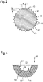
- the anchor rod assembly 10 comprises a sleeve-like additional element 50, which is shown partially cut in the embodiment shown.
- the additional element 50 surrounds the entire fastening section 16.
- the additional element 50 extends in the axial direction from the end of the fastening section 16 facing away from the shaft section 14 to the shaft section 14, the additional element 50 at the transition between the fastening section 16 and the shaft section 14 rests and is fastened with the fastening section 16.
- the additional element 50 is formed from two plastic materials, for example polyamide and a softer plastic material or foam. Accordingly, the additional element 50 may have been injection molded onto the anchor rod 12 in a two-component injection molding process, in particular on the shaft section 14, in order to form the anchor rod assembly 10.
- the tear area 52 is formed by radial web sections 53, two of which are shown.
- the radial web sections 53 extend from a radially inner inner edge 54 of the additional element 50 radially outward to a radially outer outer edge 55 of the additional element 50. Accordingly, the radial web sections 53 extend in the radial direction over the entire extent of the additional element 50.
- a circular section element 56 is provided, which is formed from the harder plastic material, for example from polyamide.
- the circular section elements 56 each comprise an angular range of approximately 60 ° in the embodiment shown.
- the radial web sections 53 and the circular section elements 56 are each arranged alternately in the circumferential direction, so that a homogeneous support area 51 and a homogeneous tear area 52 are formed in the cross-sectional plane.
- a plurality of or less radial web sections 53 can also be provided, so that correspondingly more or fewer circular section elements 56 are provided, which then each encompass a smaller or larger angular range.
- the additional element 50 preferably has a plurality of such cross-sectional planes, as shown in FIG Figure 4 are shown. Accordingly, the additional element 50 also has essentially homogeneous support and tear properties over its axial length.
- the radial web sections 53 and the circular section elements 56 extend continuously in the axial direction of the additional element 50. Accordingly, the additional element 50 tears over its entire axial length, provided that the predefined force has been reached.
- the web sections 56 generally form one or more predetermined breaking point (s) of the additional element 50.
- the predetermined breaking point or the predetermined breaking points can be formed in the additional element 50 and the required force at which the additional element 50 tears can be set via the support area 51 and the tear area 52 and the corresponding material properties of the materials used.
- the additional element 50 separates in the region of the radial web sections 53 or tears, as a result of which the anchor rod 12 enclosed by the additional element 50, in particular its fastening section 16, can engage in the torn parts of the additional element 50, so that the anchor rod 12 engages in the torn ones Parts of the additional element 50 can be anchored with the mortar sleeve adhering to it.
- the anchor rod 12 it is possible for the anchor rod 12 to find a hold in a borehole filled with synthetic resin mortar even if this would not otherwise be possible due to poor borehole cleaning and / or difficult application conditions.
- a force can be exerted on the anchor rod 12, in particular via a threaded section, not shown here, due to which the additional element 50 tears.
- the threaded section can adjoin the shaft section 14 or the shaft section 14 merges into the threaded section.
- the foremost section of the anchor rod 12 facing the bottom of the borehole is designed as a head part 20, at the free front end 22 of which a cutting edge 24 is provided which extends approximately perpendicular to the axis A of the anchor rod 12.
- the head part 20 is provided in the front area with a bevel 28 which extends up to the peripheral surface 30 of the head part 20.
- the illustrated embodiment variants of the invention consist in the formation of conveying devices 26, which are provided in the largest diameter cylindrical region 34 of the head part 20.
- the conveying devices 26 consist of a knurling of the peripheral surface 30.
- the knurling forms approximately axially extending grooves 40, which extend from the free front end 22 equipped with the cutting edge 24 to the conical section 32 of the head part 20.
- the grooves 40 have flanks 41 which extend obliquely from the groove base 42 to the peripheral surface 30. There they meet at an acute angle on the flanks 41 of adjacent grooves 40 and form a sharp edge 43 on the circumferential surface 30.
- the circumferential surface 30 provided with toothed strips in this way supports the comminution of the container, for example a plastic film, when the anchor rod rotates in the receiving bore .
- the depth t of the grooves is from about 0.5 mm to about 2.5 mm.
- the greatest width w of the grooves is about 1 mm to about 3 mm.
- the conveyor devices 26 consist of a thread-like profiling 44, which is provided in the peripheral surface 30 of the cylindrical region 34 of the head part 20.
- the thread-like profile 44 has the same direction of rotation as the coarse thread 18 of the fastening section 16.
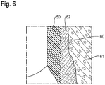
- the borehole 60 is provided in a component 61 made of concrete or the like, the borehole 60 being torn in the concrete, for example, which is why the borehole 60 has been filled with a synthetic resin mortar 62 into which the anchor rod assembly 10 has been inserted.
- the synthetic resin mortar 62 forms a mortar sleeve 63 which has formed around the additional element 50 and is connected to it.
- the additional element 50 is formed in particular from a material or materials with which the synthetic resin mortar 62 connects as if the synthetic resin mortar 62 and that were Additional element 50 a single material.
- the synthetic resin mortar 62 and the additional element 50 therefore form an integral or homogeneous bond.
- the anchor rod assembly 10 Since the synthetic resin mortar 62 has hardened, the anchor rod assembly 10, in particular the additional element 50, is firmly accommodated in the synthetic resin mortar 62.
- the anchor rod 12 can then build up an expansion effect which contributes to increasing the load-bearing capacity.
- the anchor rod assembly 10 fasten the anchor rod 12 in a borehole 60 filled with synthetic resin mortar, in particular with epoxy resin mortar, in particular even if the borehole 60 has not been cleaned beforehand.
- the additional element 50 is designed as a cap-like or sleeve-like element, which can also be referred to as a dowel, in particular a drawing dowel.
- the anchor rod explained using the example of two design variants ensures reliable comminution of the container in which the synthetic resin mortar composition and its components are contained. Due to the geometric design of the mixing section of the anchor rod according to the invention, the individual components of two- or multi-component mortar systems are intimately mixed. The mixed mortar is distributed evenly over the anchor area of the anchor rod.
- the geometry of the anchor rod according to the invention also supports the post-expansion behavior of the anchor rod, as a result of which it ensures sufficiently high holding values even in cracked subsoil when the crack opens.
Landscapes
- Engineering & Computer Science (AREA)
- General Engineering & Computer Science (AREA)
- Mechanical Engineering (AREA)
- Joining Of Building Structures In Genera (AREA)
Priority Applications (4)
| Application Number | Priority Date | Filing Date | Title |
|---|---|---|---|
| EP18192405.1A EP3620670A1 (fr) | 2018-09-04 | 2018-09-04 | Ensemble de tige d'ancrage pourvu de tête de transport |
| US17/271,656 US11802582B2 (en) | 2018-09-04 | 2019-08-20 | Anchor rod assembly with conveying head |
| EP19755633.5A EP3847379B1 (fr) | 2018-09-04 | 2019-08-20 | Ensemble de tige d'ancrage pourvu de tête de transport |
| PCT/EP2019/072216 WO2020048763A1 (fr) | 2018-09-04 | 2019-08-20 | Ensemble de barre d'ancrage doté d'une tête d'extraction |
Applications Claiming Priority (1)
| Application Number | Priority Date | Filing Date | Title |
|---|---|---|---|
| EP18192405.1A EP3620670A1 (fr) | 2018-09-04 | 2018-09-04 | Ensemble de tige d'ancrage pourvu de tête de transport |
Publications (1)
| Publication Number | Publication Date |
|---|---|
| EP3620670A1 true EP3620670A1 (fr) | 2020-03-11 |
Family
ID=63528519
Family Applications (2)
| Application Number | Title | Priority Date | Filing Date |
|---|---|---|---|
| EP18192405.1A Withdrawn EP3620670A1 (fr) | 2018-09-04 | 2018-09-04 | Ensemble de tige d'ancrage pourvu de tête de transport |
| EP19755633.5A Active EP3847379B1 (fr) | 2018-09-04 | 2019-08-20 | Ensemble de tige d'ancrage pourvu de tête de transport |
Family Applications After (1)
| Application Number | Title | Priority Date | Filing Date |
|---|---|---|---|
| EP19755633.5A Active EP3847379B1 (fr) | 2018-09-04 | 2019-08-20 | Ensemble de tige d'ancrage pourvu de tête de transport |
Country Status (3)
| Country | Link |
|---|---|
| US (1) | US11802582B2 (fr) |
| EP (2) | EP3620670A1 (fr) |
| WO (1) | WO2020048763A1 (fr) |
Citations (3)
| Publication number | Priority date | Publication date | Assignee | Title |
|---|---|---|---|---|
| DE3708764A1 (de) * | 1987-03-18 | 1988-09-29 | Upat Max Langensiepen Kg | Ankerstange fuer einen kunstharzklebeanker |
| EP0856669A1 (fr) | 1997-02-04 | 1998-08-05 | HILTI Aktiengesellschaft | Barre d'ancrage pour dispositif d'ancrage composite |
| DE29820560U1 (de) * | 1998-11-18 | 2000-04-06 | Fischer Artur Werke Gmbh | Klebeanker |
Family Cites Families (11)
| Publication number | Priority date | Publication date | Assignee | Title |
|---|---|---|---|---|
| CH333422A (de) * | 1956-09-20 | 1958-10-31 | Fischer Artur | Vorrichtung zum Befestigen von Gegenständen an Mauerwerk, Beton und dergleichen |
| US3257891A (en) * | 1965-05-20 | 1966-06-28 | Lerich Lester | Wedge type expansion bolt |
| DE2733007A1 (de) * | 1977-07-21 | 1979-02-08 | Hilti Ag | Klebeanker |
| DE3716703A1 (de) * | 1987-05-19 | 1988-12-01 | Hilti Ag | Verbundanker mit elektrischer isolation |
| DE3823163A1 (de) * | 1988-07-08 | 1990-02-01 | Hilti Ag | Ankerstange |
| DE59004679D1 (de) * | 1989-11-04 | 1994-03-31 | Upat Max Langensiepen Kg | Ankerstange. |
| DE4010051C1 (fr) * | 1990-03-29 | 1991-08-08 | Upat Gmbh & Co, 7830 Emmendingen, De | |
| DE4221853A1 (de) * | 1992-05-18 | 1993-11-25 | Fischer Artur Werke Gmbh | Anker zur Verankerung mittels einer Verbundmasse in einem Bohrloch eines Betonteils |
| US5740651A (en) * | 1994-03-18 | 1998-04-21 | Vape Rail International S.A. | Anchoring sleeve |
| DE4439861A1 (de) * | 1994-11-08 | 1996-05-09 | Fischer Artur Werke Gmbh | Ankerbolzen zur Verankerung mittels einer Verbundmasse |
| JP6991562B2 (ja) * | 2017-11-09 | 2022-01-12 | Fsテクニカル株式会社 | 接着系アンカー用のアンカーボルト、接着系アンカーおよび接着系アンカーの施工方法 |
-
2018
- 2018-09-04 EP EP18192405.1A patent/EP3620670A1/fr not_active Withdrawn
-
2019
- 2019-08-20 WO PCT/EP2019/072216 patent/WO2020048763A1/fr unknown
- 2019-08-20 US US17/271,656 patent/US11802582B2/en active Active
- 2019-08-20 EP EP19755633.5A patent/EP3847379B1/fr active Active
Patent Citations (3)
| Publication number | Priority date | Publication date | Assignee | Title |
|---|---|---|---|---|
| DE3708764A1 (de) * | 1987-03-18 | 1988-09-29 | Upat Max Langensiepen Kg | Ankerstange fuer einen kunstharzklebeanker |
| EP0856669A1 (fr) | 1997-02-04 | 1998-08-05 | HILTI Aktiengesellschaft | Barre d'ancrage pour dispositif d'ancrage composite |
| DE29820560U1 (de) * | 1998-11-18 | 2000-04-06 | Fischer Artur Werke Gmbh | Klebeanker |
Also Published As
| Publication number | Publication date |
|---|---|
| US11802582B2 (en) | 2023-10-31 |
| EP3847379B1 (fr) | 2024-01-17 |
| EP3847379A1 (fr) | 2021-07-14 |
| US20210324895A1 (en) | 2021-10-21 |
| WO2020048763A1 (fr) | 2020-03-12 |
Similar Documents
| Publication | Publication Date | Title |
|---|---|---|
| EP0352226B1 (fr) | Boulon d'ancrage | |
| DE102010043769B4 (de) | Ankerbaugruppe, insbesondere für den Berg- und Tunnelbau | |
| EP0593721B1 (fr) | Boulon d'ancrage pour l'ancrage au moyen d'une matiere composite dans un trou perce dans un element en beton | |
| EP0955476B2 (fr) | Dispositif de fixation avec une vis-auto-taraudeuse destinée à être insérée dans des éléments de construction en béton. | |
| EP0856669B1 (fr) | Barre d'ancrage pour dispositif d'ancrage composite | |
| CH650064A5 (de) | Verfahren zum setzen eines ankerbolzens und ankerbolzen zu dessen durchfuehrung. | |
| DE102006000412A1 (de) | Befestigungselement für harte Untergründe | |
| DE3009312C2 (fr) | ||
| EP1397601B1 (fr) | Tige d'ancrage | |
| EP2158407B1 (fr) | Amélioration d'un écrou d'ancrage en plastique renforcé de fibres | |
| EP0015895B1 (fr) | Tirant pour l'ancrage d'éléments de construction dans un corps de fondement | |
| EP1645757B1 (fr) | Élément d'ancrage | |
| WO2004072495A1 (fr) | Systeme d'ancrage a contre-depouille pouvant etre mis en place par liaison de forme | |
| EP3847379B1 (fr) | Ensemble de tige d'ancrage pourvu de tête de transport | |
| EP0985100B1 (fr) | Cheville d'ancrage en matiere plastique | |
| DE10311471A1 (de) | Gewindeformende Schraube für Untergründe aus harten Vollbaustoffen | |
| DE3741345C2 (de) | Verankerungsverfahren für Befestigungselemente | |
| DE102010043765B4 (de) | Ankerbaugruppe sowie Verfahren zur Herstellung einer Ankerbaugruppe | |
| EP0697530B1 (fr) | Boulon d'ancrage pour béton ou similaire | |
| WO1993010362A1 (fr) | Boulon d'ancrage a coller | |
| DE2164666A1 (de) | Ankerbolzen | |
| DE10017761B4 (de) | Verwendung eines Rohrankers mit Profilierung | |
| EP3286442B1 (fr) | Disque de remplissage pour une pièce d'ancrage en forme de tige et dispositif composé d'une piéce d'ancrage et d'un tel disque de remplissage | |
| DE19634912A1 (de) | Ankerstange für Verbundanker | |
| EP3088752B1 (fr) | Clavette et systeme de clavette |
Legal Events
| Date | Code | Title | Description |
|---|---|---|---|
| PUAI | Public reference made under article 153(3) epc to a published international application that has entered the european phase |
Free format text: ORIGINAL CODE: 0009012 |
|
| STAA | Information on the status of an ep patent application or granted ep patent |
Free format text: STATUS: THE APPLICATION HAS BEEN PUBLISHED |
|
| AK | Designated contracting states |
Kind code of ref document: A1 Designated state(s): AL AT BE BG CH CY CZ DE DK EE ES FI FR GB GR HR HU IE IS IT LI LT LU LV MC MK MT NL NO PL PT RO RS SE SI SK SM TR |
|
| AX | Request for extension of the european patent |
Extension state: BA ME |
|
| STAA | Information on the status of an ep patent application or granted ep patent |
Free format text: STATUS: THE APPLICATION IS DEEMED TO BE WITHDRAWN |
|
| 18D | Application deemed to be withdrawn |
Effective date: 20200912 |