EP3620600A1 - Beschlaganordnung für ein doppelrahmen - system - Google Patents
Beschlaganordnung für ein doppelrahmen - system Download PDFInfo
- Publication number
- EP3620600A1 EP3620600A1 EP19194398.4A EP19194398A EP3620600A1 EP 3620600 A1 EP3620600 A1 EP 3620600A1 EP 19194398 A EP19194398 A EP 19194398A EP 3620600 A1 EP3620600 A1 EP 3620600A1
- Authority
- EP
- European Patent Office
- Prior art keywords
- frame
- window
- outer frame
- fitting arrangement
- double
- Prior art date
- Legal status (The legal status is an assumption and is not a legal conclusion. Google has not performed a legal analysis and makes no representation as to the accuracy of the status listed.)
- Granted
Links
Images


Classifications
-
- E—FIXED CONSTRUCTIONS
- E05—LOCKS; KEYS; WINDOW OR DOOR FITTINGS; SAFES
- E05C—BOLTS OR FASTENING DEVICES FOR WINGS, SPECIALLY FOR DOORS OR WINDOWS
- E05C7/00—Fastening devices specially adapted for two wings
- E05C7/02—Fastening devices specially adapted for two wings for wings which lie one behind the other when closed
-
- E—FIXED CONSTRUCTIONS
- E05—LOCKS; KEYS; WINDOW OR DOOR FITTINGS; SAFES
- E05C—BOLTS OR FASTENING DEVICES FOR WINGS, SPECIALLY FOR DOORS OR WINDOWS
- E05C9/00—Arrangements of simultaneously actuated bolts or other securing devices at well-separated positions on the same wing
- E05C9/06—Arrangements of simultaneously actuated bolts or other securing devices at well-separated positions on the same wing with three or more sliding bars
- E05C9/063—Arrangements of simultaneously actuated bolts or other securing devices at well-separated positions on the same wing with three or more sliding bars extending along three or more sides of the wing or frame
-
- E—FIXED CONSTRUCTIONS
- E05—LOCKS; KEYS; WINDOW OR DOOR FITTINGS; SAFES
- E05B—LOCKS; ACCESSORIES THEREFOR; HANDCUFFS
- E05B47/00—Operating or controlling locks or other fastening devices by electric or magnetic means
- E05B47/02—Movement of the bolt by electromagnetic means; Adaptation of locks, latches, or parts thereof, for movement of the bolt by electromagnetic means
-
- E—FIXED CONSTRUCTIONS
- E06—DOORS, WINDOWS, SHUTTERS, OR ROLLER BLINDS IN GENERAL; LADDERS
- E06B—FIXED OR MOVABLE CLOSURES FOR OPENINGS IN BUILDINGS, VEHICLES, FENCES OR LIKE ENCLOSURES IN GENERAL, e.g. DOORS, WINDOWS, BLINDS, GATES
- E06B3/00—Window sashes, door leaves, or like elements for closing wall or like openings; Layout of fixed or moving closures, e.g. windows in wall or like openings; Features of rigidly-mounted outer frames relating to the mounting of wing frames
- E06B3/32—Arrangements of wings characterised by the manner of movement; Arrangements of movable wings in openings; Features of wings or frames relating solely to the manner of movement of the wing
- E06B3/34—Arrangements of wings characterised by the manner of movement; Arrangements of movable wings in openings; Features of wings or frames relating solely to the manner of movement of the wing with only one kind of movement
- E06B2003/345—Arrangements of wings characterised by the manner of movement; Arrangements of movable wings in openings; Features of wings or frames relating solely to the manner of movement of the wing with only one kind of movement with additional rotating frame within the wing
- E06B2003/346—Arrangements of wings characterised by the manner of movement; Arrangements of movable wings in openings; Features of wings or frames relating solely to the manner of movement of the wing with only one kind of movement with additional rotating frame within the wing where the additional frame rotates around a vertical axis
Definitions
- the present invention relates to a double frame system for a window, a window door or the like with a fitting arrangement, comprising a base frame with a profile in the direction of an outer frame, the outer frame each with a profile in the direction of the base frame and an inner frame, the inner frame having a profile in the direction of the outer frame, at least one pair of hinges connecting the outer frame to the inner frame at least pivotably and at least one pair of hinges connecting the outer frame to the base frame at least pivotably, the inner frame being at least pivotable completely independently of the outer frame and the fitting arrangement being operable via an actuating element, so that the outer frame and inner frame can be locked together with the base frame.
- a similar system with separately pivotable frame parts is from the DE 21 2015 000 262 U1 known.
- the wing is made up of a glass pane and a fly screen main wing and both wing parts can be rotated together in relation to the frame, but also rotated against each other.
- a disadvantage of the arrangement presented is that in order to pivot the underglass wing outwards, both wings first have to be turned into the interior, that is, a certain turning sequence is necessary in order to be able to implement all possible wing settings.
- the window sash consists of an inner and outer frame, which are combined in a base frame.
- two fittings attached to the outer frame each engage in a counter fitting on the inner and on the base frame.
- This embodiment proves to be disadvantageous in that two separate fittings have to be actuated and, for example, two drive rods are required and a gearbox for actuating the fitting has to be of a more complicated construction.
- a composite window which has an inner and an outer wing, which are rotatable about a common axis and can be folded against each other.
- the compound window is operated using a handle on the inner sash, which drives a fitting arrangement with angle fittings, which are arranged in the angles of the window and have hooks that reach into the base frame for locking, which closes both the inner and outer sash with the frame.
- the object of the invention is to provide a fitting arrangement for a double frame system that is as functional and inexpensive as possible, so that the advantages of sash frames opening outwards and inwards can be realized without high additional expenditure.
- a drive rod fitting with a drive rod is arranged on the outer frame for switching at least part of the opening and closing functions of the outer frame and inner frame.
- This configuration allows the closures of the three frame parts to be controlled centrally via a drive rod.
- several individually running drive rods are avoided and neither several, nor complicated gearboxes are required.
- all the usual opening options such as tilting position or parallel setting, can be realized via several switching positions of the actuating element.
- this is particularly easy to implement if the drive rod of the drive rod fitting drives locking elements which act both for locking with the base frame and for locking with the inner frame, which locking elements can each engage in counter elements.
- the invention can be made as space-saving and visually appealing as possible if the outer frame has a chamber for the drive rod and recesses for the locking elements are formed on both fold sides of the chamber. This means that the drive rod can be installed completely concealed, so that the drive rod is better protected from external influences and well guided. This reduces the wear on the fitting.
- the chamber is arranged approximately centrally at the same distance from the base frame and from the inner frame in the outer frame.
- This embodiment of the invention ensures that the fitting can drive the closing elements with an equally large lever arm on both locking sides. This uniform load also reduces wear and the fitting can be operated smoothly, since the chamber also ensures all-round guidance of the drive rod without additional components, and standard components can be used, as these are used in a Euro groove are provided.
- the chamber on one of the sides of the outer frame is designed as an open chamber in the form of a Euro groove.
- the closing elements on the side that has the open chamber form a smaller lever arm.
- the operation of the system can be implemented particularly advantageously if the actuating element is designed as an actuator, preferably with an electric drive.
- This design makes it easier to operate the fitting.
- the individual locking positions can be controlled in a targeted manner, and any increased clumsiness of the connecting rod fitting due to the higher number of locking points can be compensated for without any problems.
- additional positions such as tilting position or parallel parking are easier to implement.
- the fitting arrangement of the double-frame system is visually appealing and easy to handle if the actuating element carries a handle as an operating element through which the actuator can be switched. This ensures the familiar appearance of a grand piano with a control element.
- the fitting can be operated particularly simply and in the usual manner like a conventional turn-tilt fitting if the actuator acts as a support for manual actuation.
- the handle can be made smaller, since it is now primarily used to switch the actuator and not to transmit torque to the gearbox of the Espagnolette fitting is used so that less space is required when operating the handle. This improves the visual appearance of the double frame system.
- a further advantageous development of the invention is space-saving and also promotes the visual appearance if the actuator of the actuating element is at least partially embedded in the outer frame. This can then be covered, for example, by a rosette located under the control element. Thus, the actuator is arranged under the rosette and consequently the familiar appearance is not or hardly disturbed.
- the handle position can assume at least three different switch positions in a total rotation range of the handle of 180 °.
- the total turning range corresponds to the usual turning range of handles for window fittings.
- These three different positions “closed”, “turning” and “tilting” of the handle are required.
- the proposed handle can advantageously assume four different positions, which can be assigned to four different fitting positions. These include the closed position in which all locking elements are in engagement with their counter-elements, the respective rotational position of the inner and outer frames and the tilting position in which at least the inner or outer frames can be tilted.
- This range of functions is easy to implement, in particular in the case of a motorized design of the fitting arrangement.
- the operation of the fitting arrangement of the double frame system can be adapted such that the handle position can assume at least four different switch positions in a total rotation range of the handle of 360 °.
- the individual positions are separated from one another by a further range of rotation and unintentional incorrect switching can be reliably minimized. Due to the already mentioned possibility of using a shorter handle, the pivoting range of the handle does not or only barely extends beyond the outer edge of the outer frame, so that the individual frames can be pivoted in any rotational position without any problems.
- Figure 1 shows a window with an outer frame 2 rotatable against a base frame 1, which in turn holds an inner frame 3 which is rotatable against itself.
- Outer frame 2 and inner frame 3 are connected to one another via a hinge pair 8.
- Counter elements 13, which are part of the locking system, are arranged between the individual frames.
- On the outer frame there is an actuating element 10 which carries a manually operated handle 16.
- the handle 16 also serves as a handle for moving the outer frame 2.
- the handle 16 can be shortened if the actuating element is designed as an actuator, preferably an electric motor, since in this case no torque has to be transmitted mechanically from the handle 16 to a transmission .
- Figure 2 shows the window Figure 1 with revolving open inner frame 3.
- the direction of rotation is indicated by the arrow A.
- the handle 16 is in one of three possible positions, a position rotated by 180 ° to the basic position, in which the handle 16 points downward, was selected here for the release position of the inner frame 3.
- other release positions can also be selected, for example in an angular range from 0 ° to 360 °.
- a closure element 12, which is arranged on the side of the outer frame 2 facing the inner frame 3, is not in engagement with the counter element 13 and thus releases the inner frame 3 relative to the outer frame 2 for the rotary opening.
- a mushroom pin is selected as the closure element 12, which interacts with a striking plate as the counter element 13, but the closure mechanism can also be implemented via other elements, such as, for example, folding latches.
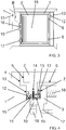
- Figure 3 shows the system according to the invention with the outer frame 2 rotatably opened.
- the arrow B indicates the direction of rotation.
- the handle 16 is now in a position rotated 90 ° to the basic position, which in this case was selected as the release position.
- the closure element 12, which is arranged between the outer frame 2 and the base frame 1 can be seen on the hinge side. In cooperation with the opposite counter element 13, this ensures that the outer frame 2 is fixed to the base frame 1.
- Figure 4 shows a horizontal section of the locking side of the double frame system.
- the cross-sections of the base frame 1, outer frame 2 and inner frame 3 can be seen and the respectively opposite, adapted profiles 4, 5, 6, 7 can be seen.
- the embodiment shown shows a chamber 14 which lies in the outer frame 2 and receives the drive rod 11.
- the drive rod 11 is arranged in a groove, preferably a euro groove, of the outer frame 2. This groove can then be designed either towards the inner frame 3 or towards the base frame 1.
- 2 recesses 15 are provided in the outer frame for the locking elements 12 arranged on the drive rod 11, which are dimensioned such that the locking elements 12 have sufficient movement space to implement the locking function.
- the recesses 15 are for the fitting arrangement shown thus designed as elongated holes, the long side of which runs parallel to the drive rod. So it is possible that a drive rod can drive both locking sides at the same time.
- Figure 5 shows a horizontal section of the hinge side of the double frame system. Also on this side is a locking point, consisting of locking element 12 and counter element 13, the locking element 12 being driven by a drive rod 11 arranged in a chamber 14.
- a locking point consisting of locking element 12 and counter element 13
- the locking element 12 being driven by a drive rod 11 arranged in a chamber 14.
- the hinge pair 9, which is arranged between the profiling 4 and the profiling 5, is responsible for the rotary bearing between the base frame 1 and the outer frame 2.
- the pivot bearing between the outer frame 2 and the inner frame 3 is ensured by the pair of hinges 8, which is arranged between the profiling 6 and the profiling 7.
Landscapes
- Engineering & Computer Science (AREA)
- Mechanical Engineering (AREA)
- Power-Operated Mechanisms For Wings (AREA)
Abstract
Description
- Die vorliegende Erfindung betrifft ein Doppelrahmen-System für ein Fenster, eine Fenstertür oder ähnlichem mit einer Beschlaganordnung, umfassend einen Grundrahmen mit einer Profilierung in Richtung eines Außenrahmens, den Außenrahmen mit jeweils einer Profilierung in Richtung des Grundrahmens und eines Innenrahmens, wobei der Innenrahmen eine Profilierung in Richtung des Außenrahmens aufweist, wobei zumindest ein Scharnierpaar den Außenrahmen mit dem Innenrahmen zumindest schwenkbar verbindet und zumindest ein Scharnierpaar den Außenrahmen mit dem Grundrahmen zumindest schwenkbar verbindet, wobei der Innenrahmen vollständig unabhängig vom Außenrahmen zumindest schwenkbar ist und die Beschlaganordnung über ein Betätigungselement bedienbar ist, sodass ein Verschluss von Außenrahmen und Innenrahmen zusammen mit dem Grundrahmen herstellbar ist.
- Ein ähnliches System mit separat schwenkbaren Rahmenteilen ist aus der
DE 21 2015 000 262 U1 bekannt. Der Flügel wird hier aus einem Unterglasflügel als auch einem Fliegengitterhauptflügel gebildet und beide Flügelteile lassen sich gemeinsam gegenüber dem Rahmen verdrehen, aber auch gegeneinander drehen. Nachteilig bei der vorgestellten Anordnung ist, dass zum Schwenken des Unterglasflügels nach außen zunächst beide Flügel in den Innenraum gedreht werden müssen, also eine gewisse Drehsequenz von Nöten ist, um alle möglichen Flügeleinstellungen realisieren zu können. - Solch ein Doppelrahmen-System ist weiterhin aus der
DE 10 2017 011 284 A1 bekannt, wobei der Fensterflügel aus einem Innen- sowie Außenrahmen besteht, welche zusammen in einem Grundrahmen gefasst sind. Um die Öffnungs- und Schließfunktion des Systems zu erfüllen, greifen zwei an dem Außenrahmen angebrachte Beschläge jeweils in einen Gegenbeschlag am Innen- und am Grundrahmen ein. Diese Ausgestaltung erweist sich dahingehend als unvorteilhaft, dass zwei separate Beschläge angesteuert werden müssen und dadurch beispielsweise zwei Treibstangen benötigt werden und ein Getriebe zur Betätigung des Beschlages komplizierter aufgebaut sein muss. - Weiterhin wird in der
DE 1 073 724 B ein Verbundfenster vorgestellt, welches einen Innen- und einem Außenflügel aufweist, welche um eine gemeinsame Achse drehbar und gegeneinander klappbar sind. Die Bedienung des Verbundfensters erfolgt über einen Handgriff am Innenflügel, wodurch eine Beschlaganordnung mit Winkelbeschlägen, welche in den Winkeln des Fensters angeordnet sind und zum Verschluss in den Grundrahmen greifende Haken aufweisen, angetrieben wird, die sowohl Innen- als auch Außenflügel mit dem Rahmen verschließt. - Der Erfindung liegt die Aufgabe zugrunde eine möglichst funktionale und kostengünstige Beschlaganordnung für ein Doppel-Rahmensystem bereitzustellen, sodass die Vorteile von nach außen und nach innen öffnenden Flügelrahmen ohne hohen Mehraufwand realisiert werden können.
- Die Aufgabe wird erfindungsgemäß dadurch gelöst, dass zur Schaltung zumindest eines Teils der Öffnungs- und Schließfunktionen von Außenrahmen und Innenrahmen ein Treibstangenbeschlag mit einer Treibstange an dem Außenrahmen angeordnet ist. Durch diese Ausgestaltung lassen sich die Verschlüsse der drei Rahmenteile zueinander zentral über eine Treibstange steuern. Somit werden mehrere einzeln laufende Treibstangen vermieden und es werden weder mehrere, noch kompliziert aufgebaute Getriebe benötigt. Neben einer Drehbewegung von Innen- und Außenrahmen sind auch alle üblichen Öffnungsmöglichkeiten, wie Kippstellung oder Parallelabstellung über mehrere Schaltstellungen des Betätigungselementes realisierbar.
- Gemäß einer vorteilhaften Weiterbildung der Erfindung gestaltet sich diese als besonders leicht umsetzbar, wenn die Treibstange des Treibstangenbeschlags sowohl zur Verriegelung mit dem Grundrahmen als auch zur Verriegelung mit dem Innenrahmen wirkende Verriegelungselemente antreibt, welche jeweils in Gegenelemente eingreifen können.
- Weiterhin lässt sich die Erfindung möglichst platzsparend und optisch ansprechend gestalten, wenn der Außenrahmen eine Kammer für die Treibstange aufweist und von der Kammer Ausnehmungen für die Verriegelungselemente zu beiden Falzseiten ausgebildet sind. Somit kann die Treibstange komplett verdeckt installiert werden, sodass die Treibstange besser vor äußeren Einflüssen geschützt und gut geführt ist. Hierdurch wird der Verschleiß des Beschlags reduziert.
- Gemäß einer weiteren vorteilhaften Weiterbildung der Erfindung ist es zu bevorzugen, wenn die Kammer in etwa mittig mit gleichem Abstand zum Grundrahmen und zum Innenrahmen im Außenrahmen angeordnet ist. Diese Ausführung der Erfindung sorgt dafür, dass der Beschlag zu beiden Verschlussseiten hin die Schließelemente mit einem gleichgroßen Hebelarm antreiben kann. Durch diese gleichmäßige Belastung wird ebenfalls der Verschleiß reduziert und der Beschlag lässt sich leichtgängig bedienen, da außerdem durch die Kammer eine Rundumführung der Treibstange ohne zusätzliche Bauteile gewährleistet ist und es können Standard-Bauteile verwendet werden, da diese für den Einsatz in einer Euro-Nut vorgesehen sind.
- Für bestimmte Anwendungsgebiete oder Sonderlösungen kann es gemäß einer weiteren Weiterbildung der Erfindung von Vorteil sein, wenn die Kammer an einer der Seiten des Außenrahmens als offene Kammer in Form einer Euro-Nut ausgebildet ist. Somit bilden die Schließelemente auf der Seite, welche die offene Kammer aufweist, einen kleineren Hebelarm.
- Besonders vorteilhaft lässt sich die Bedienung des Systems umsetzen, wenn das Betätigungselement als Aktor, bevorzugt mit elektrischem Antrieb, ausgeführt ist. Durch diese Ausführung wird die Betätigung des Beschlages erleichtert. Einerseits lassen sich so die einzelnen Schließstellungen gezielt ansteuern und eine eventuell erhöhte Schwerfälligkeit des Treibstangenbeschlags durch die höhere Anzahl an Verschlusspunkten kann so problemlos ausgeglichen werden. Zudem lassen sich zusätzliche Stellungen wie Kippstellung oder Parallelabstellung leichter umsetzen.
- Optisch ansprechend und gut zu handhaben ist die Beschlaganordnung des Doppelrahmen-Systems, wenn das Betätigungselement einen Griff als Bedienelement trägt durch welchen der Aktor geschaltet werden kann. Hiermit wird das gewohnte Erscheinungsbild eines Flügels mit Bedienelement gewahrt.
- Gemäß einer vorteilhaften Weiterbildung der Erfindung kann der Beschlag besonders einfach und in gewohnter Weise wie ein üblicher Dreh-Kipp-Beschlag bedient werden, wenn der Aktor unterstützend zur manuellen Betätigung wirkt. Dank der motorischen Unterstützung lässt sich der Griff kleiner gestalten, da dieser nun primär zur Schaltung des Aktors und nicht zum Übertrag eines Drehmomentes auf das Getriebe des Treibstangenbeschlags dient, sodass bei der Bedienung des Griffs weniger Platz von Nöten ist. Dies verbessert die optische Erscheinung des Doppelrahmen-Systems.
- Platzsparend und ebenfalls das optische Erscheinungsbild begünstigend ist eine weitere vorteilhafte Weiterbildung der Erfindung, wenn der Aktor des Betätigungselementes zumindest teilweise in den Außenrahmen eingelassen ist. Dies lässt sich dann zum Beispiel durch eine unter dem Bedienelement liegende Rosette abdecken. Somit ist der Aktor unter der Rosette angeordnet und folglich wird das gewohnte Erscheinungsbild nicht oder nur kaum gestört.
- Einer vorteilhaften Weiterbildung der Erfindung nach ist es sinnvoll, wenn die Griffstellung mindestens drei unterschiedliche Schaltstellungen in einem Gesamtdrehbereich des Griffes von 180° einnehmen kann. Der Gesamtdrehbereich entspricht dem gängigen Drehbereich von Griffen für Fensterbeschläge. Üblicherweise werden bei diesen drei unterschiedliche Stellungen "Zu", "Dreh" und "Kipp" des Griffes benötigt. Vorteilhafterweise kann der vorgeschlagene Griff vier unterschiedliche Stellungen einnehmen, welche vier unterschiedlichen Beschlagstellungen zuzuordnen sind. Diese umfassen die geschlossene Stellung in der alle Verriegelungselemente im Eingriff mit ihren Gegenelementen sind, die jeweilige Drehstellung von Innen- und Außenrahmen sowie die Kippstellung, in der zumindest Innen- oder Außenrahmen gekippt werden können. Dieser Funktionsumfang ist insbesondere bei motorischer Ausführung der Beschlaganordnung leicht realisierbar.
- Gemäß einer nächsten Vorteilhaften Weiterbildung der Erfindung lässt sich die Bedienung der Beschlaganordnung des Doppelrahmen-Systems dahin anpassen, dass die Griffstellung mindestens vier unterschiedliche Schaltstellungen in einem Gesamtdrehbereich des Griffes von 360° einnehmen kann. Hierdurch sind die einzelnen Stellungen durch einen weiteren Drehbereich voneinander getrennt und unbeabsichtigte Fehlschaltungen können zuverlässig minimiert werden. Durch die bereits erwähnte Möglichkeit einen kürzeren Griff zu verwenden, geht der Schwenkbereich des Griffes nicht oder nur kaum über die Außenkante des Außenrahmens hinaus, sodass in jeder Drehstellung des Griffes ein Schwenken der einzelnen Rahmen problemlos möglich ist.
- Die Erfindung lässt zahlreiche Ausführungsformen zu. Zur weiteren Verdeutlichung ihres Grundprinzips ist eine davon in der Zeichnung dargestellt und wird nachfolgend beschrieben. Diese zeigt in
- FIG. 1
- Ein Fenster mit einem Doppelrahmen-System und erfindungsgemäßer Beschlaganordnung im geschlossenen Zustand.
- FIG. 2
- Ein Fenster mit einem Doppelrahmen-System und erfindungsgemäßer Beschlaganordnung mit dem Innenrahmen in Drehstellung.
- FIG. 3
- Ein Fenster mit einem Doppelrahmen-System und erfindungsgemäßer Beschlaganordnung mit dem Außenrahmen in Drehstellung.
- FIG. 4
- Ein horizontaler Schnitt durch die Verschlussseite eines Fensters oberhalb des Betätigungselements mit einem Doppelrahmen-System und erfindungsgemäßer Beschlaganordnung.
- FIG. 5
- Ein horizontaler Schnitt der Bandseite eines Fensters durch ein bandseitig angeordnetes Verschlusselement mit einem Doppelrahmen-System und erfindungsgemäßer Beschlaganordnung.
-
Figur 1 zeigt ein Fenster mit einem gegen einen Grundrahmen 1 drehbaren Außenrahmen 2, welcher wiederum einen gegen sich drehbaren Innenrahmen 3 hält. Außenrahmen 2 und Innenrahmen 3 sind über ein Scharnierpaar 8 miteinander verbunden. Zwischen den einzelnen Rahmen sind jeweils Gegenelemente 13 angeordnet, welche Teil des Verschlusssystems sind. Am Außenrahmen befindet sich ein Betätigungselement 10, welches einen manuell bedienbaren Griff 16 trägt. Der Griff 16 dient darüber hinaus als Handhabe zur Bewegung des Außenrahmens 2. Weiterhin ist der Griff 16 verkürzt ausführbar, wenn das Betätigungselement als Aktor, bevorzugt elektromotorisch, ausgeführt ist, da in diesem Fall kein Drehmoment mechanisch vom Griff 16 auf ein Getriebe übertragen werden muss. Am Innenrahmen 3, welcher ein Flügelelement 18, üblicherweise eine Glasscheibe, trägt, ist ein zusätzlicher Griff 17 angebracht, welcher bei freigegebenen Innenrahmen dazu genutzt werden kann diesen zu bewegen. -
Figur 2 zeigt das Fenster ausFigur 1 mit drehgeöffneten Innenrahmen 3. Die Drehrichtung wird hierbei durch den Pfeil A angezeigt. Der Griff 16 befindet sich in einer von drei möglichen Stellungen, wobei hier für die Freigabestellung des Innenrahmens 3 eine um 180° zur Grundstellung, in welcher der Griff 16 nach unten zeigt, gedrehte Stellung gewählt wurde. In Kombination mit dem als Aktor ausgeführten Betätigungselement 10 können auch andere Freigabestellungen, beispielsweise in einem Winkelbereich von 0° bis 360° gewählt werden. Ein Verschlusselement 12, welches an der zum Innenrahmen 3 liegenden Seite des Außenrahmens 2 angeordnet ist, ist nicht mit dem Gegenelement 13 im Eingriff und gibt somit den Innenrahmen 3 gegenüber dem Außenrahmen 2 zur Drehöffnung frei. In der Darstellung ist ein Pilzzapfen als Verschlusselement 12 gewählt, welcher mit einem Schließblech als Gegenelement 13 zusammenwirkt, allerdings kann der Verschlussmechanismus auch über andere Elemente, wie beispielswiese Klappriegel umgesetzt werden. -
Figur 3 zeigt das erfindungsgemäße System mit drehgeöffneten Außenrahmen 2. Der Pfeil B zeigt die Drehrichtung an. Der Griff 16 befindet sich nun in einer 90° zur Grundstellung gedrehten Position, welche in diesem Fall als Freigabeposition gewählt wurde. In diesem Fall ist an der Bandseite das Verschlusselement 12, welches zwischen Außenrahmen 2 und Grundrahmen 1 angeordnet ist zu erkennen. Dieses sorgt im Zusammenwirken mit dem gegenüberliegenden Gegenelement 13 für die Fixierung des Außenrahmens 2 an dem Grundrahmen 1. -
Figur 4 zeigt einen horizontalen Schnitt der Verschlussseite des Doppelrahmen-Systems. Es sind die Querschnitte von Grundrahmen 1, Außenrahmen 2 und Innenrahmen 3 zu sehen und die sich jeweils gegenüberliegenden, angepassten Profilierungen 4, 5, 6, 7 sind zu erkennen. Die dargestellte Ausführungsform zeigt eine Kammer 14, welche im Außenrahmen 2 liegt und die Treibstange 11 aufnimmt. Alternativ sind auch Ausführungsformen denkbar, bei denen die Treibstange 11 in einer Nut, vorzugsweise einer Euro-Nut, des Außenrahmens 2 angeordnet ist. Diese Nut kann dann entweder zum Innenrahmen 3 oder zum Grundrahmen 1 hin ausgeführt sein. Um die Schließfunktion auf beiden Seiten steuern zu können, sind im Außenrahmen 2 Ausnehmungen 15 für die an der Treibstange 11 angeordneten Verschlusselemente 12 vorgesehen, welche so dimensioniert sind, dass die Verschlusselemente 12 ausreichend Bewegungsraum zur Umsetzung der Schließfunktion haben. Für die dargestellte Beschlaganordnung sind die Ausnehmungen 15 somit als Langlöcher ausgebildet, deren lange Seite parallel zur Treibstange verläuft. So ist es möglich, dass eine Treibstange beide Verschlussseiten gleichzeitig antreiben kann. -
Figur 5 zeigt einen horizontalen Schnitt der Bandseite des Doppelrahmen-Systems. Auch auf dieser Seite ist ein Verschlusspunkt, bestehend aus Verschlusselement 12 und Gegenelement 13, wobei das Verschlusselement 12 durch eine in einer Kammer 14 angeordneten Treibstange 11 angetrieben wird. Auf dieser Seite ist weiterhin die Drehlagerung von Außenrahmen 2 an Grundrahmen 1 und von Innenrahmen 3 an Außenrahmen 2 zu sehen, welche durch Scharnierpaare 8, 9 umgesetzt wird, die jeweils aus mindestens zwei einzelnen Scharnieren bestehen. Für die Drehlagerung zwischen Grundrahmen 1 und Außenrahmen 2 ist das Scharnierpaar 9 zuständig, welches zwischen der Profilierung 4 und der Profilierung 5 angeordnet ist. Die Drehlagerung zwischen Außenrahmen 2 und Innenrahmen 3 wird über das Scharnierpaar 8 gewährleistet, welches zwischen der Profilierung 6 und der Profilierung 7 angeordnet ist.
Claims (11)
- Doppelrahmen-System für ein Fenster, eine Fenstertür oder ähnlichem mit einer Beschlaganordnung, umfassend einen Grundrahmen (1) mit einer Profilierung (4) in Richtung eines Außenrahmens (2), den Außenrahmen (2) mit jeweils einer Profilierung (5, 6) in Richtung des Grundrahmens (1) und eines Innenrahmens (3), wobei der Innenrahmen (3) eine Profilierung (7) in Richtung des Außenrahmens aufweist, wobei zumindest ein Scharnierpaar (8) den Außenrahmen (2) mit dem Innenrahmen (3) zumindest schwenkbar verbindet und zumindest ein Scharnierpaar (9) den Außenrahmen (2) mit dem Grundrahmen (1) zumindest schwenkbar verbindet, wobei der Innenrahmen (3) vollständig unabhängig vom Außenrahmen (2) zumindest schwenkbar ist und die Beschlaganordnung über ein Betätigungselement (10) bedienbar ist, sodass ein Verschluss von Außenrahmen (2) und Innenrahmen (3) zusammen mit dem Grundrahmen (1) herstellbar ist, dadurch gekennzeichnet, dass zur Schaltung zumindest eines Teils der Öffnungs- und Schließfunktionen von Außenrahmen (2) und Innenrahmen (3) ein Treibstangenbeschlag mit einer Treibstange (11) an dem Außenrahmen (2) angeordnet ist.
- Doppelrahmen-System für ein Fenster, eine Fenstertür oder ähnlichem mit einer Beschlaganordnung nach Anspruch 1, dadurch gekennzeichnet, dass die Treibstange (11) des Treibstangenbeschlags sowohl zur Verriegelung mit dem Grundrahmen (1) als auch zur Verriegelung mit dem Innenrahmen (3) wirkende Verriegelungselemente (12) antreibt, welche jeweils in Gegenelemente (13) eingreifen können.
- Doppelrahmen-System für ein Fenster, eine Fenstertür oder ähnlichem mit einer Beschlaganordnung nach Anspruch 2, dadurch gekennzeichnet, dass der Außenrahmen (2) eine Kammer (14) für die Treibstange (11) aufweist und von der Kammer (14) Ausnehmungen (15) für die Verriegelungselemente (12) zu beiden Falzseiten ausgebildet sind.
- Doppelrahmen-System für ein Fenster, eine Fenstertür oder ähnlichem mit einer Beschlaganordnung nach Anspruch 3, dadurch gekennzeichnet, dass die Kammer (14) in etwa mittig mit gleichem Abstand zum Grundrahmen (1) und zum Innenrahmen (3) im Außenrahmen (2) angeordnet ist.
- Doppelrahmen-System für ein Fenster, eine Fenstertür oder ähnlichem mit einer Beschlaganordnung nach Anspruch 3 oder 4, dadurch gekennzeichnet, dass die Kammer (14) an einer der Seiten des Außenrahmens als offene Kammer in Form einer Euro-Nut ausgebildet ist.
- Doppelrahmen-System für ein Fenster, eine Fenstertür oder ähnlichem mit einer Beschlaganordnung nach einem der vorhergehenden Ansprüche, dadurch gekennzeichnet, dass das Betätigungselement (10) als Aktor, bevorzugt mit elektrischem Antrieb, ausgeführt ist.
- Doppelrahmen-System für ein Fenster, eine Fenstertür oder ähnlichem mit einer Beschlaganordnung nach Anspruch 6, dadurch gekennzeichnet, dass das Betätigungselement (10) einen Griff (16) als Bedienelement trägt, durch welchen der Aktor geschaltet werden kann.
- Doppelrahmen-System für ein Fenster, eine Fenstertür oder ähnlichem mit einer Beschlaganordnung nach Anspruch 6 oder 7, dadurch gekennzeichnet, dass der Aktor unterstützend zur manuellen Betätigung wirkt.
- Doppelrahmen-System für ein Fenster, eine Fenstertür oder ähnlichem mit einer Beschlaganordnung nach einem der Ansprüche 6 bis 8, dadurch gekennzeichnet, dass der Aktor des Betätigungselementes (10) zumindest teilweise in den Außenrahmen (2) eingelassen ist.
- Doppelrahmen-System für ein Fenster, eine Fenstertür oder ähnlichem mit einer Beschlaganordnung nach einem der vorhergehenden Ansprüche, dadurch gekennzeichnet, dass die Griffstellung mindestens drei unterschiedliche Schaltstellungen in einem Gesamtdrehbereich des Griffes (16) von 180° einnehmen kann.
- Doppelrahmen-System für ein Fenster, eine Fenstertür oder ähnlichem mit einer Beschlaganordnung nach einem der vorhergehenden Ansprüche, dadurch gekennzeichnet, dass die Griffstellung mindestens drei unterschiedliche Schaltstellungen in einem Gesamtdrehbereich des Griffes (16) von 360° einnehmen kann.
Applications Claiming Priority (1)
| Application Number | Priority Date | Filing Date | Title |
|---|---|---|---|
| DE102018215345.0A DE102018215345A1 (de) | 2018-09-10 | 2018-09-10 | Beschlaganordnung für ein Doppelrahmen-System |
Publications (2)
| Publication Number | Publication Date |
|---|---|
| EP3620600A1 true EP3620600A1 (de) | 2020-03-11 |
| EP3620600B1 EP3620600B1 (de) | 2021-06-16 |
Family
ID=67809349
Family Applications (1)
| Application Number | Title | Priority Date | Filing Date |
|---|---|---|---|
| EP19194398.4A Active EP3620600B1 (de) | 2018-09-10 | 2019-08-29 | Beschlaganordnung für ein doppelrahmen - system |
Country Status (2)
| Country | Link |
|---|---|
| EP (1) | EP3620600B1 (de) |
| DE (1) | DE102018215345A1 (de) |
Citations (4)
| Publication number | Priority date | Publication date | Assignee | Title |
|---|---|---|---|---|
| DE1073724B (de) | 1960-01-21 | Kopenhagen Villum Benedikt Kann Rasmussen | Verbundfenster mit im Abstand voneinander gekuppelten Rahmen | |
| CN204002307U (zh) * | 2014-08-25 | 2014-12-10 | 杨帆 | 一种单执手控制窗纱一体的五金型材系统 |
| DE212015000262U1 (de) | 2015-09-30 | 2017-07-03 | Qiwu Chen | Mit Fliegengitter versehene(s), nach innen öffnende(s) Tür bzw. Fenster mit nach außen öffnendem Glasflügel und Drückergarnitur sowie Scharnier dafür |
| DE102017011284A1 (de) | 2016-12-10 | 2018-06-14 | Serdar Ersin | Doppelrahmen-System |
-
2018
- 2018-09-10 DE DE102018215345.0A patent/DE102018215345A1/de not_active Withdrawn
-
2019
- 2019-08-29 EP EP19194398.4A patent/EP3620600B1/de active Active
Patent Citations (4)
| Publication number | Priority date | Publication date | Assignee | Title |
|---|---|---|---|---|
| DE1073724B (de) | 1960-01-21 | Kopenhagen Villum Benedikt Kann Rasmussen | Verbundfenster mit im Abstand voneinander gekuppelten Rahmen | |
| CN204002307U (zh) * | 2014-08-25 | 2014-12-10 | 杨帆 | 一种单执手控制窗纱一体的五金型材系统 |
| DE212015000262U1 (de) | 2015-09-30 | 2017-07-03 | Qiwu Chen | Mit Fliegengitter versehene(s), nach innen öffnende(s) Tür bzw. Fenster mit nach außen öffnendem Glasflügel und Drückergarnitur sowie Scharnier dafür |
| DE102017011284A1 (de) | 2016-12-10 | 2018-06-14 | Serdar Ersin | Doppelrahmen-System |
Also Published As
| Publication number | Publication date |
|---|---|
| DE102018215345A1 (de) | 2020-03-12 |
| EP3620600B1 (de) | 2021-06-16 |
Similar Documents
| Publication | Publication Date | Title |
|---|---|---|
| EP1085153A2 (de) | Verriegelbares Dreh- und/oder Schiebeflügelsystem | |
| DE2603240C2 (de) | Beschlag für einen kipp- und schiebbaren Flügel von Fenstern, Türen o.dgl. | |
| EP3622139B1 (de) | Fenster oder tür mit einbruchsicherer kippöffnungsbegrenzung | |
| DE202014000876U1 (de) | Beschlag eines zumindest hebbaren, vorzugsweise aber auch verschiebbaren Flügels von Fenstern oder Türen | |
| DE2439321A1 (de) | In form eines fensters, einer tuere oder dergleichen ausgebildeter drehfluegel | |
| DE3022163A1 (de) | Dreh-kipp-beschlag fuer fenster, tueren o.dgl. mit spaltlueftung | |
| EP0096744A2 (de) | Drehkippbeschlag | |
| EP3620600B1 (de) | Beschlaganordnung für ein doppelrahmen - system | |
| EP2886757B1 (de) | Fenster oder Tür | |
| EP2149661B1 (de) | Gebäudeabschluss in sprengwirkungshemmender und/oder einbruchhemmender Ausführung | |
| DE202009007430U1 (de) | Beschlagsystem | |
| DE202013008784U1 (de) | Beschlag eines zumindest hebbaren, vorzugsweise aber auch verschiebbaren Flügels von Fenstern oder Türen | |
| DE102006013332A1 (de) | Fenster- oder Türelement mit einem automatischen Antrieb | |
| EP0945579A2 (de) | Lüftungseinrichtung | |
| DE20316561U1 (de) | Fenster oder Tür | |
| DE20002467U1 (de) | Drehkippbeschlag | |
| EP1309767B1 (de) | Dreh-kipp-beschlag für fenster, türen od. dgl. | |
| EP2374972B1 (de) | Beschlag für Fenster, Türen oder dergleichen | |
| DE2457169A1 (de) | Kantenverschluss fuer fenster und tueren | |
| DE4027088A1 (de) | Schloss, insbesondere panikschloss | |
| DE102016004916A1 (de) | Fenstersystem und/oder Türsystem | |
| EP2824265B1 (de) | Beschlagsystem | |
| DE3715044A1 (de) | Stangenschloss fuer tueren od. dgl. | |
| WO2015176695A1 (de) | Panik-schloss-vorrichtung für eine fluchttür eines sektional-tores oder eines sektional-hub-falttores | |
| EP2468996B1 (de) | Treibstangenbeschlag für ein Dreh-/Kippfenster mit einer Ausstellschere |
Legal Events
| Date | Code | Title | Description |
|---|---|---|---|
| PUAI | Public reference made under article 153(3) epc to a published international application that has entered the european phase |
Free format text: ORIGINAL CODE: 0009012 |
|
| STAA | Information on the status of an ep patent application or granted ep patent |
Free format text: STATUS: THE APPLICATION HAS BEEN PUBLISHED |
|
| AK | Designated contracting states |
Kind code of ref document: A1 Designated state(s): AL AT BE BG CH CY CZ DE DK EE ES FI FR GB GR HR HU IE IS IT LI LT LU LV MC MK MT NL NO PL PT RO RS SE SI SK SM TR |
|
| AX | Request for extension of the european patent |
Extension state: BA ME |
|
| STAA | Information on the status of an ep patent application or granted ep patent |
Free format text: STATUS: REQUEST FOR EXAMINATION WAS MADE |
|
| 17P | Request for examination filed |
Effective date: 20200812 |
|
| RBV | Designated contracting states (corrected) |
Designated state(s): AL AT BE BG CH CY CZ DE DK EE ES FI FR GB GR HR HU IE IS IT LI LT LU LV MC MK MT NL NO PL PT RO RS SE SI SK SM TR |
|
| RIC1 | Information provided on ipc code assigned before grant |
Ipc: E05B 47/02 20060101ALN20201216BHEP Ipc: E06B 3/36 20060101ALI20201216BHEP Ipc: E05C 7/02 20060101AFI20201216BHEP Ipc: E05C 9/06 20060101ALI20201216BHEP |
|
| GRAP | Despatch of communication of intention to grant a patent |
Free format text: ORIGINAL CODE: EPIDOSNIGR1 |
|
| STAA | Information on the status of an ep patent application or granted ep patent |
Free format text: STATUS: GRANT OF PATENT IS INTENDED |
|
| INTG | Intention to grant announced |
Effective date: 20210203 |
|
| GRAS | Grant fee paid |
Free format text: ORIGINAL CODE: EPIDOSNIGR3 |
|
| GRAA | (expected) grant |
Free format text: ORIGINAL CODE: 0009210 |
|
| STAA | Information on the status of an ep patent application or granted ep patent |
Free format text: STATUS: THE PATENT HAS BEEN GRANTED |
|
| AK | Designated contracting states |
Kind code of ref document: B1 Designated state(s): AL AT BE BG CH CY CZ DE DK EE ES FI FR GB GR HR HU IE IS IT LI LT LU LV MC MK MT NL NO PL PT RO RS SE SI SK SM TR |
|
| REG | Reference to a national code |
Ref country code: GB Ref legal event code: FG4D Free format text: NOT ENGLISH |
|
| REG | Reference to a national code |
Ref country code: CH Ref legal event code: EP |
|
| REG | Reference to a national code |
Ref country code: DE Ref legal event code: R096 Ref document number: 502019001624 Country of ref document: DE |
|
| REG | Reference to a national code |
Ref country code: AT Ref legal event code: REF Ref document number: 1402462 Country of ref document: AT Kind code of ref document: T Effective date: 20210715 |
|
| REG | Reference to a national code |
Ref country code: IE Ref legal event code: FG4D Free format text: LANGUAGE OF EP DOCUMENT: GERMAN |
|
| REG | Reference to a national code |
Ref country code: SE Ref legal event code: TRGR |
|
| REG | Reference to a national code |
Ref country code: LT Ref legal event code: MG9D |
|
| PG25 | Lapsed in a contracting state [announced via postgrant information from national office to epo] |
Ref country code: HR Free format text: LAPSE BECAUSE OF FAILURE TO SUBMIT A TRANSLATION OF THE DESCRIPTION OR TO PAY THE FEE WITHIN THE PRESCRIBED TIME-LIMIT Effective date: 20210616 Ref country code: LT Free format text: LAPSE BECAUSE OF FAILURE TO SUBMIT A TRANSLATION OF THE DESCRIPTION OR TO PAY THE FEE WITHIN THE PRESCRIBED TIME-LIMIT Effective date: 20210616 Ref country code: FI Free format text: LAPSE BECAUSE OF FAILURE TO SUBMIT A TRANSLATION OF THE DESCRIPTION OR TO PAY THE FEE WITHIN THE PRESCRIBED TIME-LIMIT Effective date: 20210616 Ref country code: BG Free format text: LAPSE BECAUSE OF FAILURE TO SUBMIT A TRANSLATION OF THE DESCRIPTION OR TO PAY THE FEE WITHIN THE PRESCRIBED TIME-LIMIT Effective date: 20210916 |
|
| REG | Reference to a national code |
Ref country code: NL Ref legal event code: MP Effective date: 20210616 |
|
| PG25 | Lapsed in a contracting state [announced via postgrant information from national office to epo] |
Ref country code: LV Free format text: LAPSE BECAUSE OF FAILURE TO SUBMIT A TRANSLATION OF THE DESCRIPTION OR TO PAY THE FEE WITHIN THE PRESCRIBED TIME-LIMIT Effective date: 20210616 Ref country code: NO Free format text: LAPSE BECAUSE OF FAILURE TO SUBMIT A TRANSLATION OF THE DESCRIPTION OR TO PAY THE FEE WITHIN THE PRESCRIBED TIME-LIMIT Effective date: 20210916 Ref country code: RS Free format text: LAPSE BECAUSE OF FAILURE TO SUBMIT A TRANSLATION OF THE DESCRIPTION OR TO PAY THE FEE WITHIN THE PRESCRIBED TIME-LIMIT Effective date: 20210616 Ref country code: GR Free format text: LAPSE BECAUSE OF FAILURE TO SUBMIT A TRANSLATION OF THE DESCRIPTION OR TO PAY THE FEE WITHIN THE PRESCRIBED TIME-LIMIT Effective date: 20210917 |
|
| PG25 | Lapsed in a contracting state [announced via postgrant information from national office to epo] |
Ref country code: SM Free format text: LAPSE BECAUSE OF FAILURE TO SUBMIT A TRANSLATION OF THE DESCRIPTION OR TO PAY THE FEE WITHIN THE PRESCRIBED TIME-LIMIT Effective date: 20210616 Ref country code: RO Free format text: LAPSE BECAUSE OF FAILURE TO SUBMIT A TRANSLATION OF THE DESCRIPTION OR TO PAY THE FEE WITHIN THE PRESCRIBED TIME-LIMIT Effective date: 20210616 Ref country code: NL Free format text: LAPSE BECAUSE OF FAILURE TO SUBMIT A TRANSLATION OF THE DESCRIPTION OR TO PAY THE FEE WITHIN THE PRESCRIBED TIME-LIMIT Effective date: 20210616 Ref country code: PT Free format text: LAPSE BECAUSE OF FAILURE TO SUBMIT A TRANSLATION OF THE DESCRIPTION OR TO PAY THE FEE WITHIN THE PRESCRIBED TIME-LIMIT Effective date: 20211018 Ref country code: CZ Free format text: LAPSE BECAUSE OF FAILURE TO SUBMIT A TRANSLATION OF THE DESCRIPTION OR TO PAY THE FEE WITHIN THE PRESCRIBED TIME-LIMIT Effective date: 20210616 Ref country code: EE Free format text: LAPSE BECAUSE OF FAILURE TO SUBMIT A TRANSLATION OF THE DESCRIPTION OR TO PAY THE FEE WITHIN THE PRESCRIBED TIME-LIMIT Effective date: 20210616 Ref country code: ES Free format text: LAPSE BECAUSE OF FAILURE TO SUBMIT A TRANSLATION OF THE DESCRIPTION OR TO PAY THE FEE WITHIN THE PRESCRIBED TIME-LIMIT Effective date: 20210616 Ref country code: SK Free format text: LAPSE BECAUSE OF FAILURE TO SUBMIT A TRANSLATION OF THE DESCRIPTION OR TO PAY THE FEE WITHIN THE PRESCRIBED TIME-LIMIT Effective date: 20210616 |
|
| PG25 | Lapsed in a contracting state [announced via postgrant information from national office to epo] |
Ref country code: PL Free format text: LAPSE BECAUSE OF FAILURE TO SUBMIT A TRANSLATION OF THE DESCRIPTION OR TO PAY THE FEE WITHIN THE PRESCRIBED TIME-LIMIT Effective date: 20210616 |
|
| REG | Reference to a national code |
Ref country code: DE Ref legal event code: R097 Ref document number: 502019001624 Country of ref document: DE |
|
| PG25 | Lapsed in a contracting state [announced via postgrant information from national office to epo] |
Ref country code: MC Free format text: LAPSE BECAUSE OF FAILURE TO SUBMIT A TRANSLATION OF THE DESCRIPTION OR TO PAY THE FEE WITHIN THE PRESCRIBED TIME-LIMIT Effective date: 20210616 |
|
| PLBE | No opposition filed within time limit |
Free format text: ORIGINAL CODE: 0009261 |
|
| REG | Reference to a national code |
Ref country code: BE Ref legal event code: MM Effective date: 20210831 |
|
| STAA | Information on the status of an ep patent application or granted ep patent |
Free format text: STATUS: NO OPPOSITION FILED WITHIN TIME LIMIT |
|
| PG25 | Lapsed in a contracting state [announced via postgrant information from national office to epo] |
Ref country code: DK Free format text: LAPSE BECAUSE OF FAILURE TO SUBMIT A TRANSLATION OF THE DESCRIPTION OR TO PAY THE FEE WITHIN THE PRESCRIBED TIME-LIMIT Effective date: 20210616 |
|
| 26N | No opposition filed |
Effective date: 20220317 |
|
| PG25 | Lapsed in a contracting state [announced via postgrant information from national office to epo] |
Ref country code: LU Free format text: LAPSE BECAUSE OF NON-PAYMENT OF DUE FEES Effective date: 20210829 Ref country code: AL Free format text: LAPSE BECAUSE OF FAILURE TO SUBMIT A TRANSLATION OF THE DESCRIPTION OR TO PAY THE FEE WITHIN THE PRESCRIBED TIME-LIMIT Effective date: 20210616 |
|
| PG25 | Lapsed in a contracting state [announced via postgrant information from national office to epo] |
Ref country code: IT Free format text: LAPSE BECAUSE OF FAILURE TO SUBMIT A TRANSLATION OF THE DESCRIPTION OR TO PAY THE FEE WITHIN THE PRESCRIBED TIME-LIMIT Effective date: 20210616 Ref country code: IE Free format text: LAPSE BECAUSE OF NON-PAYMENT OF DUE FEES Effective date: 20210829 Ref country code: FR Free format text: LAPSE BECAUSE OF NON-PAYMENT OF DUE FEES Effective date: 20210831 Ref country code: BE Free format text: LAPSE BECAUSE OF NON-PAYMENT OF DUE FEES Effective date: 20210831 |
|
| REG | Reference to a national code |
Ref country code: CH Ref legal event code: PL |
|
| PG25 | Lapsed in a contracting state [announced via postgrant information from national office to epo] |
Ref country code: LI Free format text: LAPSE BECAUSE OF NON-PAYMENT OF DUE FEES Effective date: 20220831 Ref country code: CH Free format text: LAPSE BECAUSE OF NON-PAYMENT OF DUE FEES Effective date: 20220831 |
|
| P01 | Opt-out of the competence of the unified patent court (upc) registered |
Effective date: 20230516 |
|
| PG25 | Lapsed in a contracting state [announced via postgrant information from national office to epo] |
Ref country code: CY Free format text: LAPSE BECAUSE OF FAILURE TO SUBMIT A TRANSLATION OF THE DESCRIPTION OR TO PAY THE FEE WITHIN THE PRESCRIBED TIME-LIMIT Effective date: 20210616 |
|
| PG25 | Lapsed in a contracting state [announced via postgrant information from national office to epo] |
Ref country code: HU Free format text: LAPSE BECAUSE OF FAILURE TO SUBMIT A TRANSLATION OF THE DESCRIPTION OR TO PAY THE FEE WITHIN THE PRESCRIBED TIME-LIMIT; INVALID AB INITIO Effective date: 20190829 |
|
| PG25 | Lapsed in a contracting state [announced via postgrant information from national office to epo] |
Ref country code: MK Free format text: LAPSE BECAUSE OF FAILURE TO SUBMIT A TRANSLATION OF THE DESCRIPTION OR TO PAY THE FEE WITHIN THE PRESCRIBED TIME-LIMIT Effective date: 20210616 |
|
| PG25 | Lapsed in a contracting state [announced via postgrant information from national office to epo] |
Ref country code: TR Free format text: LAPSE BECAUSE OF FAILURE TO SUBMIT A TRANSLATION OF THE DESCRIPTION OR TO PAY THE FEE WITHIN THE PRESCRIBED TIME-LIMIT Effective date: 20210616 |
|
| PG25 | Lapsed in a contracting state [announced via postgrant information from national office to epo] |
Ref country code: MT Free format text: LAPSE BECAUSE OF FAILURE TO SUBMIT A TRANSLATION OF THE DESCRIPTION OR TO PAY THE FEE WITHIN THE PRESCRIBED TIME-LIMIT Effective date: 20210616 |
|
| REG | Reference to a national code |
Ref country code: DE Ref legal event code: R081 Ref document number: 502019001624 Country of ref document: DE Owner name: AUG. WINKHAUS SE & CO. KG, DE Free format text: FORMER OWNER: AUG. WINKHAUS GMBH & CO. KG, 48291 TELGTE, DE Ref country code: DE Ref legal event code: R081 Ref document number: 502019001624 Country of ref document: DE Owner name: AUG. WINKHAUS SE, DE Free format text: FORMER OWNER: AUG. WINKHAUS GMBH & CO. KG, 48291 TELGTE, DE |
|
| REG | Reference to a national code |
Ref country code: DE Ref legal event code: R081 Ref document number: 502019001624 Country of ref document: DE Owner name: AUG. WINKHAUS SE, DE Free format text: FORMER OWNER: AUG. WINKHAUS SE & CO. KG, 48291 TELGTE, DE |
|
| PGFP | Annual fee paid to national office [announced via postgrant information from national office to epo] |
Ref country code: DE Payment date: 20250819 Year of fee payment: 7 |
|
| PGFP | Annual fee paid to national office [announced via postgrant information from national office to epo] |
Ref country code: GB Payment date: 20250822 Year of fee payment: 7 |
|
| PGFP | Annual fee paid to national office [announced via postgrant information from national office to epo] |
Ref country code: AT Payment date: 20250819 Year of fee payment: 7 |
|
| PGFP | Annual fee paid to national office [announced via postgrant information from national office to epo] |
Ref country code: SE Payment date: 20250821 Year of fee payment: 7 |