EP3620318A1 - Hydraulische drosselvorrichtung - Google Patents
Hydraulische drosselvorrichtung Download PDFInfo
- Publication number
- EP3620318A1 EP3620318A1 EP19194544.3A EP19194544A EP3620318A1 EP 3620318 A1 EP3620318 A1 EP 3620318A1 EP 19194544 A EP19194544 A EP 19194544A EP 3620318 A1 EP3620318 A1 EP 3620318A1
- Authority
- EP
- European Patent Office
- Prior art keywords
- throttle device
- component
- throttle
- hydraulic
- gap
- Prior art date
- Legal status (The legal status is an assumption and is not a legal conclusion. Google has not performed a legal analysis and makes no representation as to the accuracy of the status listed.)
- Granted
Links
Images



Classifications
-
- B—PERFORMING OPERATIONS; TRANSPORTING
- B60—VEHICLES IN GENERAL
- B60K—ARRANGEMENT OR MOUNTING OF PROPULSION UNITS OR OF TRANSMISSIONS IN VEHICLES; ARRANGEMENT OR MOUNTING OF PLURAL DIVERSE PRIME-MOVERS IN VEHICLES; AUXILIARY DRIVES FOR VEHICLES; INSTRUMENTATION OR DASHBOARDS FOR VEHICLES; ARRANGEMENTS IN CONNECTION WITH COOLING, AIR INTAKE, GAS EXHAUST OR FUEL SUPPLY OF PROPULSION UNITS IN VEHICLES
- B60K7/00—Disposition of motor in, or adjacent to, traction wheel
- B60K7/0015—Disposition of motor in, or adjacent to, traction wheel the motor being hydraulic
Definitions
- the invention relates to a hydraulic throttle device for a sealing system of a rotating device, preferably for a sealing system of a hydrostatic wheel hub motor, the rotating device comprising a first and a second component which can be rotated relative to one another about an axis of rotation.
- the invention further relates to a hydrostatic wheel hub motor and a motor vehicle with such a throttle device.
- the stator of the wheel hub motors is usually screwed to the axle stub and the rotor to the wheel hub. This creates a pressure chamber (also called a control chamber) between the wheel hub motor, stub axle and wheel hub. Since the wheel hub rotates during operation and the wheel bearings must be protected from environmental influences, a sealing system or a sealing device is also used, which is usually located between the steering knuckle and the wheel bearing facing the center of the vehicle. Due to the high pressures that arise, an additional throttle or seal must be applied against high pressures so that this sealing device is not pressed out of the hub by the pressure.
- a hydraulic throttle device preferably a throttle device for a sealing system of a rotating device, the rotating device comprising a first and a second component, which can be rotated relative to one another about an axis of rotation D.
- the sealing system can be a sealing system for a machine for sealing a shaft between a first with a first fluid, in particular a liquid, e.g. B. oil, filled space and a second with a second fluid, e.g. B. air, filled space, wherein the first fluid in the first space a larger Has pressure as the second fluid in the second space.
- the sealing system can be, for example, a sealing system of a wheel part with a hydrostatic wheel hub motor or a sealing system of a hydrostatic wheel hub motor.
- the hydraulic throttle device comprises a hydraulic throttle device which is arranged on the first component in a rotationally fixed manner.
- the throttle device has a throttle gap, the bottom wall and the top wall of which, viewed in the radial direction R of the axis of rotation D, are arranged in a rotationally fixed manner relative to one another and are formed by the throttle device.
- the throttle device can thus also be referred to as a gap throttle.
- the hydraulic throttle device further comprises at least one rotary seal which seals the throttle device with respect to the second component of the rotary device which can be rotated relative to the throttle device.
- the throttle gap is delimited in the radial direction both above and below by a wall or boundary surface which is formed by the throttle device.
- the throttle gap is therefore not from an outside of a rotating component to the throttle gap, for. B. a wave limited.
- the components of the flow restrictor through which they flow do not move towards each other.
- a particular advantage of the invention is therefore that damage to the throttle gap due to the flow of foreign particles during the rotational movement can be prevented or at least effectively reduced, since the two opposite walls (edge surfaces) of the throttle gap do not rotate relative to one another and therefore there is no rotational movement, would pull the smallest foreign body in the hydraulic fluid into the throttle gap (additional).
- the rotating throttle device of the rotating device e.g. B. in a wheel part with a hydrostatic motor, is thus functionally divided into a throttle and a sealing component.
- the throttle device serves only as a throttle, not as a seal to the rotating component, while the rotary seal in turn has no throttle function.
- the rotary seal therefore still allows the wheel part to rotate, but prevents flow between rotating components.
- the throttle gap is preferably a fixed, rigid gap.
- the wall of the throttle gap is preferably made of a non-elastic material, more preferably made of a metallic material.
- the throttle gap is preferably a fixed, rigid gap.
- the wall of the throttle gap is preferably made of a non-elastic material, more preferably made of a metallic material.
- the sealing system may typically have a seal in the axial direction in front of and behind the hydraulic throttle device, arranged between a steering knuckle and a wheel bearing, namely an inner seal that is exposed to high hydraulic pressure and an outer seal that seals against the environment, which is lower Is exposed to pressure, since the liquid hitting the outer seal must first flow through the throttle gap of the throttle device.
- the throttle device has two components arranged in a manner fixed against relative rotation and coaxial to the axis of rotation.
- the upper wall of the throttle gap is formed by a first outer surface of the first component and the lower wall is formed by a second outer surface of the second components, which is spaced radially from the first outer surface.
- Such an embodiment with two components allows the throttle gap to be manufactured with precise manufacturing technology.
- a one-component design of the throttle device is also possible, but the throttle gap would then have to be drilled, for example, which is less advantageous in terms of production technology.
- the two components of the throttle device are ring-shaped, preferably are formed as concentrically arranged metal rings.
- the throttle gap can be designed as a rigid annular gap or a rigid partial annular gap.
- the two components of the throttle device can preferably be components which are arranged concentrically with one another and / or are rigid components.
- the two components of the throttle device can be connected to one another in a rotationally fixed manner by means of a press fit.
- a press fit This in turn enables the two components to be connected in a technically reliable and cost-effective manner in a rotationally fixed manner.
- the first component of the throttle device in order to form the anti-rotation device between the first and second components, can be formed in a groove that is connected to the second outer surface of the second component in axial direction A via a protrusion formed on the first outer surface in axial direction A. molded, intervene.
- the press fit and / or the combination of projection and groove can simultaneously serve as a limitation in order to form a first discharge channel, via which the liquid emerging from the throttle gap can be discharged.
- the rotary seal can be arranged in the radial direction between the throttle device and the second component. Furthermore, the rotary seal can be designed as a radial sealing ring or as an arrangement of a plurality of radial sealing rings.
- the throttle device can be arranged in a rotationally fixed manner on the first component by means of an anti-rotation device, for example in the form of an additional component such as a pin-shaped anti-rotation device.
- the throttle device can be sealed off from the first component by means of a seal arranged between the throttle device and the first component, wherein the seal can be a sealing ring, for example.
- the first component can be a wheel hub or a component fixedly attached to the wheel hub and the second component can be an axle stub or a component fixed to the axle stub, preferably a sealant carrier of the axle stub.
- the second component can be a wheel hub or a component fixedly attached to the wheel hub and the first component can be an axle stub or a component fixed to the axle stub, preferably a sealant carrier of the axle stub.
- the invention further relates to a sealing system, a hydrostatic wheel hub motor and / or a motor vehicle, each comprising a hydraulic throttle device, as described in this document.
- the motor vehicle is preferably a commercial vehicle, such as a truck or bus.
- Figure 1 is a longitudinal section of a rotating device 3 for a sealing system with a hydraulic throttle device 1 according to an embodiment of the invention.
- the rotating device 3 comprises a first and a second component which can be rotated relative to one another about an axis of rotation D.
- the hydraulic throttle device is a hydraulic throttle device 1 for a hydrostatic wheel hub motor.
- the rotating device 3 comprises an axle stub 6 of a vehicle with a sealant carrier 5a fastened thereon and a wheel hub 4a which rotates relative to the axle stub 6 and the sealant carrier 5a.
- Figure 1 shows only a partial section of stub axle 6 and wheel hub 5.
- Figure 1 shows only a partial view of the rotating device 3 and that part that lies above the axis of rotation D.
- the part below the axis of rotation D is constructed accordingly.
- the axis of rotation is illustrated by the dashed line D; the axial direction is identified by the reference symbol A and the radial direction is identified by the reference symbol R.
- the hydraulic throttle device 1 comprises one on the first component 4, which in the exemplary embodiment of FIG Figure 1 corresponds to the wheel hub 4a, non-rotatably arranged hydraulic throttle device 10.
- the throttle device has a throttle gap 11, the lower 11a and upper 11b walls of which — seen in the radial direction R of the axis of rotation D — are arranged in a rotationally fixed manner relative to one another and are formed by the throttle device 10.
- the throttle device 10 is formed by two metal rings 13, 14 arranged in a rotationally fixed manner, coaxially and concentrically to the axis of rotation D.
- the upper wall 11b of the throttle gap 11 is defined by a radially inner circumferential surface of the outer metal ring 13 in the radial direction R and the lower wall 11a of the throttle gap 11 is formed by a radially outer peripheral surface of the inner metal ring 14 in the radial direction R.
- the throttle gap 11 forms a narrow, rigid flow channel in the form of an annular gap through which the liquid of the hydrostatic wheel hub motor in the pressure chamber in Figure 1 can flow from left to right, as illustrated by arrow F, which represents the fluid flow through the throttle gap 11.
- the throttle gap is thus a fixed, rigid gap and the wall of the throttle gap is made according to the embodiment from a non-elastic material, here from a metallic material.
- the two components 13, 14 of the throttle device are connected to one another in a rotationally fixed manner on a contact surface (contact surface) 18 by means of a press fit.
- one of the metal rings 13 has a projection formed in the axial direction A in the form of a clamping lug 15, which is pressed into a groove 16 of the other metal ring 14.
- the throttle device 1 further comprises at least one rotary seal 8, which seals the throttle device 10 with respect to the second component 5 of the rotary device 3, here the sealant carrier 5a, which can be rotated relative to the throttle device 10.
- the rotary seal 8 is arranged in the radial direction between the throttle device 10 and the component rotating relative thereto, ie the sealant carrier 5a.
- the throttle device 10 is arranged in a rotationally fixed manner on the wheel hub 4a by means of a pin-shaped anti-rotation device 7 and is arranged by means of a seal 9, for example, between the throttle device 10 and the wheel hub 4a.
- the throttle device At the end of the throttle gap 11, the throttle device has a free piece 17 which, in the circumferential direction of the rings 13, 14, form an outlet channel through which the liquid emerging from the throttle gap 11 can drain, up to an exposure point at which the anti-rotation device is used to form the anti-rotation device between the two components 13, 14 of the throttle device 10 is exposed to form a further discharge duct for Draining the fluid.
- the throttle gap 11 is thus delimited in the radial direction both above and below by a wall or boundary surface which is formed by the throttle device 10, in particular by an outer surface of the rigid metal rings 13, 14.
- the throttle gap is therefore not from an outside of a rotating component to the throttle gap, for. B. a wave limited.
- the components of the flow restrictor through which they flow therefore do not move towards each other, i.e. the two opposite walls (edge surfaces) 11a, 11b of the throttle gap 11 do not rotate relative to one another, so that there is no rotational movement which would (additionally) pull the smallest foreign bodies in the hydraulic fluid into the throttle gap.
- the rotating throttle device of the rotating device e.g. B. in a wheel part with a hydrostatic motor, is thus functionally divided into a throttle component, i.e. the throttle device 10, and a sealing component, i.e. the rotary seal 8.
- the throttle device 10 serves only as a throttle, not as a seal to the rotating component, while the rotary seal in turn has no throttle function.
- the rotary seal therefore still allows the wheel part to rotate, but prevents flow between rotating components.
- the sealing system may typically have a seal in the axial direction in front of and behind the hydraulic throttle device, arranged between a steering knuckle and a wheel bearing, namely an inner seal that is exposed to high hydraulic pressure and an outer seal that seals against the environment, which is lower Is exposed to pressure, since the liquid hitting the outer seal must first flow through the throttle gap of the throttle device. This seals the pressure chamber (control chamber of the hydrostatic wheel hub motor).
- Figure 5 shows a sectional view of a rotating device 3 with sealing system 2, which shows a hydraulic throttle device 1 of a hydrostatic wheel hub motor according to an embodiment of the invention.
- the seals include, in particular, an inner seal 21 that is exposed to high hydraulic pressure and an outer, environmental seal 22 that is subjected to lower pressure, since the liquid impinging on the outer seal previously flows through the throttle gap of the throttle device got to.
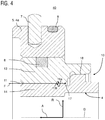
- FIG. 4 shows a sectional view of a hydraulic throttle device 40 according to a further embodiment of the invention.
- the special feature of this embodiment variant is only that the order in the radial direction R of the throttle device 10 and the rotary seal 8 is interchanged.
- the throttle device 40 is arranged on the stub shaft 6 or on a component which is fixed to the stub shaft 6 in a rotationally fixed manner.
- the structure of the throttle device 40 with the two concentrically, coaxially and non-rotatably arranged metal rings 13, 14, which form a throttle gap 11 between them, is otherwise the same as that previously described for the previous embodiment.
- the metal ring 14 of the throttle device 10 which is arranged adjacent to the component 5, 4a rotating relative to the throttle device, has a receiving groove in which a rotary seal 8 is held in a rotationally fixed manner.
- the rotary seal 8 seals the throttle device 10 with respect to a component 5 rotating relative thereto, which in turn is fixed in a rotationally fixed manner to a further component via an anti-rotation device 7 and a seal 9.
Landscapes
- Engineering & Computer Science (AREA)
- Chemical & Material Sciences (AREA)
- Combustion & Propulsion (AREA)
- Transportation (AREA)
- Mechanical Engineering (AREA)
- Sealing Devices (AREA)
Abstract
Description
- Die Erfindung betrifft eine hydraulische Drosselvorrichtung für ein Dichtsystem einer Drehvorrichtung, vorzugsweise für ein Dichtsystem eines hydrostatischen Radnabenmotors, wobei die Drehvorrichtung ein erstes und ein zweites Bauteil umfasst, die um eine Drehachse relativ zueinander verdrehbar sind. Die Erfindung betrifft ferner einen hydrostatischen Radnabenmotor und ein Kraftfahrzeug mit einer solchen Drosselvorrichtung.
- Es ist aus dem Stand der Technik bekannt, die von einem zentralen Antriebsmotor eines Fahrzeugs nicht-angetriebene Achse mit hydrostatischen Radnabenmotoren auszustatten, um die nicht-angetriebenen Achse bei Bedarf für mehr Traktion in eine angetriebene Achse zu verwandeln, wobei lediglich beispielhaft auf die Offenlegungsschriften
EP 2 559 581 A2 undEP 1 886 861 A2 verwiesen wird. - Der Stator der Radnabenmotoren wird dazu üblicherweise mit dem Achsstummel und der Rotor mit der Radnabe verschraubt. Dadurch entsteht ein Druckraum (auch Steuerraum genannt) zwischen Radnabenmotor, Achsstummel und Radnabe. Da sich die Radnabe im Betrieb dreht und die Radlager vor Umwelteinflüssen geschützt werden müssen, kommen des Weiteren ein Dichtsystem bzw. eine Dichtvorrichtung zum Einsatz, die sich üblicherweise zwischen dem Achsschenkel und dem der Fahrzeugmitte zugewandten Radlager befindet. Durch die hohen entstehenden Drücke, muss daher eine zusätzliche Drossel oder Dichtung gegen hohe Drücke aufgebracht werden, damit diese Dichtvorrichtung nicht durch den Druck aus der Nabe gedrückt wird.
- Nach dem Stand der Technik sind verschiedene Dichtungen oder Drosseln bekannt, die in derartigen Systemen zum Einsatz kommen. Wie aus der Offenlegungsschrift
DE 10 2012 220 748 A1 bekannt ist, können sogenannte Spaltdrosseln eingesetzt werden, die drehfest mit der Radnabe verbunden sind und mit einer Gegenfläche (z.B. Achsstummel) eine kontaktlose Verjüngung des Strömungsquerschnitts erzeugen. Je nach Länge und Größe des verjüngten Querschnitts kann ein Druckabfall erzeugt werden, sodass der resultierende Druck hinter dieser Drossel gering genug ist, damit eine konventionelle Dichtung nicht beschädigt wird. Des Weiteren sind nach den OffenlegungsschriftenWO 2011/040843 A1 undWO 2013/068377 A2 Dichtungen bekannt, die vor einer fettgeschmierten Lagereinheit angebracht werden können, und damit überhaupt keine Strömung in Richtung der Lagereinheit bzw. der weiteren Lagerdichtungen zulassen. Diese aus dem Stand der Technik bekannten Lösungsansätze haben jedoch Nachteile. - So weisen hydraulische Dichtvorrichtungen nach
WO 2011/040843 A1 undWO 2013/068377 A2 den Nachteil auf, dass sie auch hohe Druckspitzen komplett abfangen müssen, da keine Hydraulikflüssigkeit in die fettgeschmierte Lagereinheit vordringen darf. Dazu werden diese Systeme mehrteilig ausgeführt, damit sie einfach montierbar bleiben und die hohen Anforderungen an Dichtungen und deren Gegenlaufflächen erfüllen. - Die deutlich einfacheren Drosselringe, wie aus der
DE 10 2012 220 748 A1 bekannt, weisen jedoch den Nachteil auf, dass sie bei einem Druckunterschied vor und hinter der Drossel einen Volumenstrom durch die Drossel, bestehend aus Drosselring und Gegenfläche, erzeugen. Im Rahmen der Erfindung wurde festgestellt, dass die Gefahr besteht, dass kleinste Fremdkörper in der Hydraulikflüssigkeit in den Drosselspalt gezogen werden und durch die Relativbewegung beider Komponenten zueinander die Drosselflächen beschädigen, da sich die beiden Elemente der Drossel auch relativ zueinander drehen. - Es ist somit eine Aufgabe der Erfindung, eine verbesserte Drosselvorrichtung bereitzustellen, bei der kleinste Fremdkörper keine Beschädigung der Drossel verursachen oder zumindest das Risiko für derartige Beschädigungen reduziert ist.
- Diese Aufgabe wird durch eine Drosselvorrichtung mit den Merkmalen des unabhängigen Anspruchs gelöst. Vorteilhafte Ausführungsformen und Anwendungen der Erfindung sind Gegenstand der abhängigen Ansprüche und werden in der folgenden Beschreibung unter teilweiser Bezugnahme auf die Figuren näher erläutert.
- Gemäß einem allgemeinen Gesichtspunkt der Erfindung wird eine hydraulische Drosselvorrichtung bereitgestellt, vorzugsweise eine Drosselvorrichtung für ein Dichtsystem einer Drehvorrichtung, wobei die Drehvorrichtung ein erstes und ein zweites Bauteil umfasst, die um eine Drehachse D relativ zueinander verdrehbar sind. Das Dichtsystem kann ein Dichtsystem für eine Maschine zur Abdichtung einer Welle zwischen einem ersten mit einem ersten Fluid, insbesondere eine Flüssigkeit, z. B. Öl, gefüllten Raum und einem zweiten mit einem zweiten Fluid, z. B. Luft, gefüllten Raum sein, wobei das erste Fluid in dem ersten Raum einen größeren Druck aufweist als das zweite Fluid in dem zweiten Raum. Das Dichtsystem kann beispielsweise ein Dichtsystem eines Radteils mit hydrostatischem Radnabenmotor oder ein Dichtsystem eines hydrostatischen Radnabenmotors sein.
- Die hydraulische Drosselvorrichtung umfasst eine an dem ersten Bauteil drehfest angeordnete hydraulische Drosseleinrichtung. Die Drosseleinrichtung weist einen Drosselspalt auf, dessen - in Radialrichtung R der Drehachse D gesehen - untere Wandung und obere Wandung zueinander drehfest angeordnet sind und durch die Drosseleinrichtung gebildet sind. Die Drosseleinrichtung kann somit auch als Spaltdrossel bezeichnet werden. Die hydraulische Drosselvorrichtung umfasst ferner mindestens eine Rotationsdichtung, die die Drosseleinrichtung gegenüber dem relativ zur Drosseleinrichtung verdrehbaren zweiten Bauteil der Drehvorrichtung abdichtet.
- Mit anderen Worten wird der Drosselspalt in Radialrichtung sowohl oben als auch unten durch eine Wand oder Begrenzungsfläche begrenzt, die durch die Drosseleinrichtung gebildet ist. Der Drosselspalt wird daher nicht von einer Außenseite eines sich zum Drosselspalt drehenden Bauteils, z. B. einer Welle begrenzt. Die Bauteile der durchströmten Spaltdrossel bewegen sich dabei zueinander nicht. Ein besonderer Vorzug der Erfindung liegt somit darin, dass Beschädigungen des Drosselspalts durch Durchströmung mit Fremdpartikeln während der Drehbewegung verhindert oder zumindest wirksam reduziert werden können, da sich die beiden gegenüberliegenden Wandungen (Randflächen) des Drosselspaltes nicht relativ zueinander drehen und somit auch kein Drehbewegung vorliegt, die kleinste Fremdkörper in der Hydraulikflüssigkeit in den Drosselspalt (zusätzlich) ziehen würde.
- Die drehende Drosselvorrichtung der Drehvorrichtung, z. B. in einem Radteil mit hydrostatischen Motor, ist somit funktional aufgeteilt in eine Drossel- und eine Dichtkomponente. Die Drosseleinrichtung dient dabei nur als Drossel, nicht als Abdichtung zum rotierenden Bauteil, während die Rotationsdichtung ihrerseits keine Drosselfunktion hat. Die Rotationsdichtung ermöglicht daher dennoch eine Drehbewegung des Radteils, verhindert aber eine Strömung zwischen rotierenden Komponenten.
- Der Drosselspalt ist vorzugsweise ein fester, starrer Spalt. Die Wandung des Drosselspalts ist vorzugsweise aus einem nicht-elastischem Material, weiter vorzugsweise aus einem metallischen Werkstoff.
- Der Drosselspalt ist vorzugsweise ein fester, starrer Spalt. Die Wandung des Drosselspalts ist vorzugsweise aus einem nicht-elastischem Material, weiter vorzugsweise aus einem metallischen Werkstoff.
- Das Dichtsystem kann typischerweise in Axialrichtung vor und hinter der hydraulischen Drosselvorrichtung jeweils eine Abdichtung aufweisen, angeordnet zwischen einem Achsschenkel und einem Radlager, nämlich eine innere Dichtung, die einem hohem hydraulischen Druck ausgesetzt ist und eine äußere, gegen die Umwelt abdichtende Dichtung, die einem niedrigerem Druck ausgesetzt ist, da das auf die äußere Dichtung auftreffende Flüssigkeit zuvor durch den Drosselspalt der Drosselvorrichtung fließen muss.
- Gemäß einer besonders bevorzugten Ausführungsform weist die Drosseleinrichtung zwei zueinander drehfest und koaxial zu der Drehachse angeordneten Komponenten auf. Hierbei ist die obere Wandung des Drosselspalts durch eine erste Außenfläche der ersten Komponente und die untere Wandung durch eine zweite, zur ersten Außenfläche in Radialrichtung beabstandete Außenfläche der zweiten Komponenten gebildet. Eine solche Ausführung mit zwei Komponenten erlaubt eine herstellungstechnisch präzise Herstellung des Drosselspalts. Eine 1-komponentige Ausführung der Drosseleinrichtung ist auch möglich, jedoch müsste dann der Drosselspalt beispielsweise gebohrt werden, was herstellungstechnisch weniger vorteilhaft ist.
- Gemäß einem weiteren Aspekt dieser Ausführungsform besteht die Möglichkeit, dass die zwei Komponenten der Drosseleinrichtung ringförmig ausgebildet sind, vorzugsweise als konzentrisch angeordnete Metallringe ausgebildet sind. Ferner kann der Drosselspalt als starrer Ringspalt oder starrer Teilringspalt ausgebildet sein. Die zwei Komponenten der Drosseleinrichtung können vorzugsweise zueinander konzentrisch angeordnete und/oder starre Komponenten sein.
- Gemäß einem weiteren Aspekt können die zwei Komponenten der Drosseleinrichtung mittels einer Presspassung miteinander drehfest verbunden sein. Dies ermöglicht wiederum ein herstellungstechnisch zuverlässiges und kostengünstiges drehfestes Verbinden der beiden Komponenten. Alternativ oder zusätzlich kann zur Ausbildung der Verdrehsicherung zwischen der ersten und zweiten Komponente die erste Komponente der Drosseleinrichtung über einen an die erste Außenfläche in Axialrichtung A angeformten Vorsprung, vorzugsweise eine Klemmnase, in eine Nut, die an die zweite Außenfläche der zweiten Komponente in Axialrichtung A angeformt ist, eingreifen. Die Presspassung und/oder die Kombination aus Vorsprung und Nut können gleichzeitig als Begrenzung dienen, um einen ersten Ableitungskanal auszubilden, über den die aus dem Drosselspalt heraustretende Flüssigkeit abgeleitet werden kann.
- Ferner ist es vorteilhaft, die Verdrehsicherung zur Ausbildung der Drehsicherung zwischen den beiden Komponenten in mindestens einem an den Drosselspalt angrenzenden Bereich auszusetzen, zur Ausbildung eines zweiten Ableitungskanals zum Ableiten des Fluides aus dem Drosselspalt und aus dem ersten Ableitungskanal.
- Gemäß einer weiteren Ausführungsform kann die Rotationsdichtung in Radialrichtung zwischen der Drosseleinrichtung und dem zweiten Bauteil angeordnet sein. Ferner kann die Rotationsdichtung als Radialdichtring oder als Anordnung mehrerer Radialdichtringe ausgebildet sein.
- Gemäß einem weiteren Aspekt kann die Drosseleinrichtung mittels einer Verdrehsicherung, beispielsweise in Form eines zusätzlichen Bauteils, wie einer stiftförmigen Verdrehsicherung, drehfest am ersten Bauteil angeordnet sein. Ferner kann die Drosseleinrichtung mittels einer zwischen Drosseleinrichtung und ersten Bauteil angeordneten Dichtung zum ersten Bauteil hin abgedichtet sein, wobei die Dichtung beispielsweise ein Dichtring sein kann.
- Es sind unterschiedliche Anordnungsvarianten der Drosseleinrichtung und der Rotationsdichtung in Radialrichtung möglich. Gemäß einer ersten Variante kann das erste Bauteil eine Radnabe oder ein drehfest an der Radnabe befestigtes Bauteil sein und das zweite Bauteil kann ein Achsstummel oder ein drehfest am Achsstummel befestigtes Bauteil, vorzugsweise ein Dichtmittelträger des Achsstummels, sein. Gemäß einer zweiten Variante kann das zweite Bauteil eine Radnabe oder ein drehfest an der Radnabe befestigtes Bauteil sein und das erste Bauteil kann ein Achsstummel oder ein drehfest am Achsstummel befestigtes Bauteil, vorzugsweise ein Dichtmittelträger des Achsstummels, sein.
- Gemäß einem weiteren Aspekt betrifft die Erfindung ferner ein Dichtsystem, einen hydrostatischen Radnabenmotor und/oder ein Kraftfahrzeug, jeweils umfassend eine hydraulische Drosselvorrichtung, wie in diesem Dokument beschrieben. Das Kraftfahrzeug ist vorzugsweise ein Nutzfahrzeug, wie beispielsweise ein Lastkraftwagen oder Omnibus.
- Die zuvor beschriebenen bevorzugten Ausführungsformen und Merkmale der Erfindung sind beliebig miteinander kombinierbar. Weitere Einzelheiten und Vorteile der Erfindung werden im Folgenden unter Bezug auf die beigefügten Zeichnungen beschrieben. Es zeigen:
- Figur 1
- einen Teilansicht im Schnitt einer Drehvorrichtung mit einer hydraulischen Drosselvorrichtung gemäß einer Ausführungsform der Erfindung;
- Figur 2
- eine perspektivische Ansicht der Drosselvorrichtung gemäß einer Ausführungsform der Erfindung;
- Figur 3
- eine Teilansicht im Schnitt der Drosselvorrichtung gemäß einer Ausführungsform der Erfindung;
- Figur 4
- einen Schnittansicht einer hydraulischen Drosselvorrichtung gemäß einer weiteren Ausführungsform der Erfindung; und
- Figur 5
- einen Schnittansicht einer Drehvorrichtung mit Dichtsystem, das eine hydraulische Drosselvorrichtung gemäß einer Ausführungsform der Erfindung umfasst.
- Gleiche oder äquivalente Elemente sind in allen Figuren mit denselben Bezugszeichen bezeichnet und zum Teil nicht gesondert beschrieben.
- In
Figur 1 ist ein Längsschnitt einer Drehvorrichtung 3 für ein Dichtsystem mit einer hydraulischen Drosselvorrichtung 1 gemäß einer Ausführungsform der Erfindung dargestellt. Die Drehvorrichtung 3 umfasst ein erstes und ein zweites Bauteil, die um eine Drehachse D relativ zueinander verdrehbar sind. Vorliegend handelt es sich bei der hydraulischen Drosselvorrichtung um eine hydraulische Drosselvorrichtung 1 für einen hydrostatischen Radnabenmotor. Entsprechend umfasst die Drehvorrichtung 3 einen Achsstummel 6 eines Fahrzeugs mit einem hieran befestigten Dichtmittelträger 5a und eine Radnabe 4a, die sich relativ zum Achsstummel 6 und zum Dichtmittelträger 5a dreht.Figur 1 zeigt jeweils nur einen Teilausschnitt von Achsstummel 6 und Radnabe 5.Figur 1 zeigt nur eine Teilansicht der Drehvorrichtung 3 und zwar desjenigen Teils, der oberhalb der Drehachse D liegt. Der unterhalb der Drehachse D liegende Teil ist entsprechend analog aufgebaut. Die Drehachse ist durch die gestrichelte Linie D illustriert; die Axialrichtung ist mit dem Bezugszeichen A und die Radialrichtung ist mit dem Bezugszeichen R gekennzeichnet. - Die hydraulische Drosselvorrichtung 1 umfasst eine an dem ersten Bauteil 4, das in dem Ausführungsbeispiel der
Figur 1 der Radnabe 4a entspricht, drehfest angeordnete hydraulische Drosseleinrichtung 10. Die Drosselreinrichtung weist einen Drosselspalt 11 auf, dessen - in Radialrichtung R der Drehachse D gesehen - untere 11a und obere 11b Wandung zueinander drehfest angeordnet und durch die Drosseleinrichtung 10 gebildet sind. - Die Drosseleinrichtung 10 wird dabei gebildet durch zwei zueinander drehfest, koaxial und konzentrisch zu der Drehachse D angeordnete Metallringe 13, 14. Hierbei wird die obere Wandung 11b des Drosselspalts 11 durch eine radial innenliegende Umfangsfläche des in Radialrichtung R äußeren Metallringes 13 und die untere Wandung 11a des Drosselspalts 11 durch eine radial außenliegende Umfangsfläche des in Radialrichtung R inneren Metallrings 14 gebildet. Der Drosselspalt 11 bildet einen engen starren Durchflusskanal in Form eines Ringspaltes aus, durch den Flüssigkeit des hydrostatischen Radnabenmotors im Druckraum in
Figur 1 von links nach rechts strömen kann, wie es durch den Pfeil F, der den Fluiddurchfluss durch den Drosselspalt 11 darstellt, illustriert ist. Der Drosselspalt ist somit ein fester, starrer Spalt und die Wandung des Drosselspalts ist gemäß dem Ausführungsbeispiel aus einem nicht-elastischem Material, hier aus einem metallischen Werkstoff. - Die beiden Komponenten 13, 14 der Drosseleinrichtung sind an einer Kontaktfläche (Auflagefläche) 18 mittels einer Presspassung miteinander drehfest verbunden. Zur Ausbildung der Verdrehsicherung weist einer der Metallringe 13 einen in Axialrichtung A angeformten Vorsprung in Form einer Klemmnase 15 auf, die eine Nut 16 des anderen Metallrings 14 eingepresst ist.
- Die Drosselvorrichtung 1 umfasst ferner mindestens eine Rotationsdichtung 8, die die Drosseleinrichtung 10 gegenüber dem relativ zur Drosseleinrichtung 10 verdrehbaren zweiten Bauteil 5 der Drehvorrichtung 3, hier dem Dichtmittelträger 5a, abdichtet. Die Rotationsdichtung 8 ist in Radialrichtung zwischen der Drosseleinrichtung 10 und dem sich relativ hierzu drehenden Bauteil, d. h. dem Dichtmittelträger 5a, angeordnet. Die Rotationsdichtung 8 umfasst in dem in
Figur 1 gezeigten Ausführungsbeispiel eine Anordnung aus zwei Radialdichtringen 8, die in Axialrichtung A zueinander versetzt angeordnet sind. - Die Drosseleinrichtung 10 ist mittels einer stiftförmigen Verdrehsicherung 7 drehfest an der Radnabe 4a angeordnet und mittels einer zwischen Drosseleinrichtung 10 und Radnabe 4a angeordneten Dichtung 9, z. B. in Form eines Dichtrings, zur Radnabe 4a hin abgedichtet.
- Am Ende des Drosselspalts 11 weist die Drosseleinrichtung ein Freistück 17 auf, die in Umfangsrichtung der Ringe 13, 14 einen Ablaufkanal bilden, über den die aus dem Drosselspalt 11 austretende Flüssigkeit abließen kann, bis zur einer Aussetzstelle, an der die Verdrehsicherung zur Ausbildung der Drehsicherung zwischen den beiden Komponenten 13, 14 der Drosseleinrichtung 10 ausgesetzt ist, zur Ausbildung eines weiteren Ableitungskanals zum Ableiten des Fluides. Diese Merkmale sind ferner in den Ansichten der Drosselvorrichtung 1 der
Figuren 2 und 3 gut erkennbar. - Wie vorstehend bereits dargelegt wurde, wird somit der Drosselspalt 11 in Radialrichtung sowohl oben als auch unten durch eine Wand oder Begrenzungsfläche begrenzt, die durch die Drosseleinrichtung 10, insbesondere durch eine Außenfläche der starren Metallringe 13, 14 gebildet ist. Der Drosselspalt wird daher nicht von einer Außenseite eines sich zum Drosselspalt drehenden Bauteils, z. B. einer Welle begrenzt. Die Bauteile der durchströmten Spaltdrossel bewegen sich daher zueinander nicht, d.h. die beiden gegenüberliegenden Wandungen (Randflächen) 11a, 11b des Drosselspaltes 11 drehen sich nicht relativ zueinander, so dass keine Drehbewegung vorliegt, die kleinste Fremdkörper in der Hydraulikflüssigkeit in den Drosselspalt (zusätzlich) ziehen würde. Entsprechend können Beschädigungen des Drosselspalts 11 durch Durchströmung mit Fremdpartikeln während der Drehbewegung der Drehvorrichtung 3 verhindert oder zumindest wirksam reduziert werden. Die drehende Drosselvorrichtung der Drehvorrichtung, z. B. in einem Radteil mit hydrostatischen Motor, ist somit funktional aufgeteilt in eine Drosselkomponente, d.h. die Drosseleinrichtung 10, und eine Dichtkomponente, d.h. die Rotationsdichtung 8. Die Drosseleinrichtung 10 dient dabei nur als Drossel, nicht als Abdichtung zum rotierenden Bauteil, während die Rotationsdichtung ihrerseits keine Drosselfunktion hat. Die Rotationsdichtung ermöglicht daher dennoch eine Drehbewegung des Radteils, verhindert aber eine Strömung zwischen rotierenden Komponenten.
- Das Dichtsystem kann typischerweise in Axialrichtung vor und hinter der hydraulischen Drosselvorrichtung jeweils eine Abdichtung aufweisen, angeordnet zwischen einem Achsschenkel und einem Radlager, nämlich eine innere Dichtung, die einem hohem hydraulischen Druck ausgesetzt ist und eine äußere, gegen die Umwelt abdichtende Dichtung, die einem niedrigerem Druck ausgesetzt ist, da das auf die äußere Dichtung auftreffende Flüssigkeit zuvor durch den Drosselspalt der Drosselvorrichtung fließen muss. Hierdurch wird der Druckraum (Steuerraum des hydrostatischen Radnabenmotors) abgedichtet.
- In
Figur 1 sind ferner zwei Radlager 20 erkennbar. Das inFigur 1 links gezeigte Radlager 20 ist einem hohem Druck ausgesetzt, wohingegen das rechts gezeigte Radlager 20 einer hierzu geringerem Druck ausgesetzt ist, das Flüssigkeit, die auf das rechte Radlager 20 trifft, durch den Drosselspalt 11 gedrosselt wurde. - Die eigentliche Abdichtung des Dichtsystems erfolgt mittels zweier in Axialrichtung vor und hinter der hydraulischen Drosselvorrichtung 1 vorgesehenen Abdichtungen, angeordnet zwischen einem Achsschenkel 6 und einem Radlager 20, die in dem Ausschnitt der
Figur 1 nicht mehr dargestellt sind. Diese Abdichtungen 21, 22 sind jedoch inFigur 5 erkennbar. -
Figur 5 zeigt eine Schnittansicht einer Drehvorrichtung 3 mit Dichtsystem 2, das eine hydraulische Drosselvorrichtung 1 eines hydrostatischen Radnabenmotors gemäß einer Ausführungsform der Erfindung zeigt. Die Abdichtungen umfassen insbesondere ein eine innere Dichtung 21, die einem hohem hydraulischen Druck ausgesetzt ist und eine äußere, gegen die Umwelt abdichtende Dichtung 22, die einem niedrigerem Druck ausgesetzt ist, da die auf die äußere Dichtung auftreffende Flüssigkeit zuvor durch den Drosselspalt der Drosselvorrichtung fließen muss. -
Figur 4 zeigt eine Schnittansicht einer hydraulischen Drosselvorrichtung 40 gemäß einer weiteren Ausführungsform der Erfindung. Die Besonderheit dieser Ausführungsvariante liegt lediglich darin, dass die Reihenfolge in Radialrichtung R von Drosseleinrichtung 10 und Rotationsdichtung 8 vertauscht sind. Entsprechend ist die Drosseleinrichtung 40 am Achsstummel 6 oder an einem Bauteil, das drehfest am Achsstummel 6 befestigt ist, drehfest angeordnet. Der Aufbau der Drosseleinrichtung 40 mit den beiden konzentrisch, koaxial und drehfest zueinander angeordneten Metallringen 13, 14, die einen Drosselspalt 11 zwischen sich ausbilden, ist ansonsten entsprechend wie sie zuvor für das vorherige Ausführungsbeispiel beschrieben wurde. Der Metallring 14 der Drosseleinrichtung 10, der benachbart zum sich relativ zur Drosseleinrichtung drehenden Bauteil 5, 4a angeordnet ist, weist eine Aufnahmenut auf, in der eine Rotationsdichtung 8 drehfest gehaltert ist. Die Rotationsdichtung 8 dichtet die Drosseleinrichtung 10 gegenüber ein sich relativ hierzu drehenden Bauteil 5 ab, das wiederum über eine Verdrehsicherung 7 und eine Dichtung 9 drehfest an einem weiteren Bauteil befestigt ist. - Obwohl die Erfindung unter Bezugnahme auf bestimmte Ausführungsbeispiele beschrieben worden ist, ist es für einen Fachmann ersichtlich, dass verschiedene Änderungen ausgeführt werden können und Äquivalente als Ersatz verwendet werden können, ohne den Bereich der Erfindung zu verlassen. Folglich soll die Erfindung nicht auf die offenbarten Ausführungsbeispiele begrenzt sein, sondern soll alle Ausführungsbeispiele umfassen, die in den Bereich der beigefügten Patentansprüche fallen. Insbesondere beansprucht die Erfindung auch Schutz für den Gegenstand und die Merkmale der Unteransprüche unabhängig von den in Bezug genommenen Ansprüchen.
-
- 1
- Hydraulische Drosselvorrichtung
- 2
- Dichtsystem eines hydrostatischen Radnabenmotors
- 3
- Drehvorrichtung
- 4
- Drehfest zur Drosseleinrichtung angeordnetes Bauteil
- 4a
- Radnabe
- 5
- Relativ zur Drosseleinrichtung drehendes Bauteil
- 5a
- Dichtmittelträger
- 6
- Achsstummel
- 7
- Verdrehsicherung
- 8
- Rotationsdichtung, vorzugsweise Radialdichtring
- 9
- Dichtring
- 10
- Hydraulische Drosseleinrichtung
- 11
- Drosselspalt
- 11a
- Untere Wandung des Drosselspalts
- 11b
- Obere Wandung des Drosselspalts
- 12
- Freistück
- 13
- Ring
- 14
- Ring
- 15
- Klemmnase
- 16
- Nut
- 17
- Ablaufkanal
- 18
- Kontaktfläche
- 20
- Radlager
- 21
- Innere Dichtung
- 22
- Äußere Dichtung
- 40
- Hydraulische Drosselvorrichtung
- A
- Axialrichtung
- R
- Radialrichtung
- D
- Drehachse
- F
- Fluiddurchfluss
Claims (12)
- Hydraulische Drosselvorrichtung (1; 40) für ein Dichtsystem (2) einer Drehvorrichtung (3), vorzugsweise für ein Dichtsystem eines Radteils (3) mit hydrostatischem Radnabenmotor, wobei die Drehvorrichtung (3) ein erstes und ein zweites Bauteil (4, 5) umfasst, die um eine Drehachse (D) relativ zueinander verdrehbar sind, umfassendeine an dem ersten Bauteil (4) drehfest angeordnete hydraulische Drosseleinrichtung (10), aufweisend einen Drosselspalt (11), dessen - in Radialrichtung (R) der Drehachse (D) gesehen - untere (11a) und obere (11b) Wandung zueinander drehfest angeordnet und durch die Drosseleinrichtung (10) gebildet sind; undmindestens eine Rotationsdichtung (8), die die Drosseleinrichtung (10) gegenüber dem relativ zur Drosseleinrichtung (10) verdrehbaren zweiten Bauteil (5) der Drehvorrichtung (3) abdichtet.
- Hydraulische Drosselvorrichtung (1; 40) nach Anspruch 1, wobei die Drosseleinrichtung (10) zwei zueinander drehfest und koaxial zu der Drehachse angeordneten Komponenten (13, 14) aufweist und die obere Wandung (11b) des Drosselspalts (11) durch eine erste Außenfläche der ersten Komponente (13) und die untere Wandung (11a) durch eine zweite, zur ersten Außenfläche in Radialrichtung beabstandete Außenfläche der zweiten Komponente (14) gebildet sind.
- Hydraulische Drosselvorrichtung (1; 40) nach Anspruch 2,a) wobei die zwei Komponenten (13, 14) der Drosseleinrichtung (10) ringförmig ausgebildet sind, vorzugsweise als konzentrisch angeordnete Metallringe ausgebildet sind; und/oderb) wobei der Drosselspalt (11) als starrer Ringspalt oder starrer Teilringspalt ausgebildet ist.
- Hydraulische Drosselvorrichtung (1, 40) nach Anspruch 2 oder 3,a) wobei die zwei Komponenten (13, 14) der Drosseleinrichtung mittels einer Presspassung miteinander drehfest verbunden sind; und/oderb) wobei zur Ausbildung der Verdrehsicherung zwischen der ersten und zweiten Komponente (13, 14) die erste Komponente (13) der Drosseleinrichtung (10) über einen an die ersten Außenfläche in Axialrichtung (A) angeformten Vorsprung, vorzugsweise eine Klemmnase (15), in eine Nut (16), die an die zweite Außenfläche der zweiten Komponente (14) in Axialrichtung (A) angeformt ist, eingreift.
- Hydraulische Drosselvorrichtung (1; 40) nach einem der Ansprüche 2 bis 4, wobei eine Verdrehsicherung zur Ausbildung der Drehsicherung zwischen den beiden Komponenten der Drosseleinrichtung (10) in mindestens einem an den Drosselspalt angrenzenden Bereich ausgesetzt ist, zur Ausbildung eines Ableitungskanals zum Ableiten von Fluid.
- Hydraulische Drosselvorrichtung nach einem der vorhergehenden Ansprüche, wobei die Rotationsdichtung (8) in Radialrichtung zwischen der Drosseleinrichtung (10) und dem zweiten Bauteil (5) angeordnet ist.
- Hydraulische Drosselvorrichtung (1; 40) nach einem der vorhergehenden Ansprüche, wobei die Rotationsdichtung (8) als Radialdichtring oder als Anordnung mehrerer Radialdichtringe ausgebildet ist.
- Hydraulische Drosselvorrichtung (1; 40) nach einem der vorhergehenden Ansprüche, wobei die Drosseleinrichtung (10)a) mittels einer Verdrehsicherung (7) drehfest am ersten Bauteil (4) angeordnet ist; und/oderb) mittels einer zwischen Drosseleinrichtung (10) und ersten Bauteil (4) angeordneten Dichtung (9) zum ersten Bauteil (4) hin abgedichtet ist, wobei die Dichtung vorzugsweise ein Dichtring ist.
- Hydraulische Drosselvorrichtung (1; 40) nach einem der vorhergehenden Ansprüche, wobeia) das erste Bauteil (4) eine Radnabe (4a) oder ein drehfest an der Radnabe befestigtes Bauteil und das zweite Bauteil (5) ein Achsstummel oder ein drehfest am Achsstummel befestigtes Bauteil, vorzugsweise ein Dichtmittelträger (5a) des Achsstummels (6), ist; oderb) das zweite Bauteil (5) eine Radnabe (4a) oder ein drehfest an der Radnabe befestigtes Bauteil und das erste Bauteil (4) ein Achsstummel oder ein drehfest am Achsstummel befestigtes Bauteil, vorzugsweise ein Dichtmittelträger (5a) des Achsstummels (6), ist.
- Hydraulische Drosselvorrichtung (1; 40) nach einem der vorhergehenden Ansprüche, wobeia) der Drosselspalt als fester und/oder starrer Spalt ausgebildet ist; und/oderb) die Wandung des Drosselspalt aus einem nicht-elastischem Material, beispielsweise aus einem metallischen Werkstoff gebildet ist.
- Hydrostatischer Radnabenmotor, umfassend eine hydraulische Drosselvorrichtung (1; 40) nach einem der vorhergehenden Ansprüche.
- Kraftfahrzeug, vorzugsweise Nutzfahrzeug, umfassend eine hydraulische Drosselvorrichtung (1; 40) nach einem der vorhergehenden Ansprüche.
Applications Claiming Priority (1)
| Application Number | Priority Date | Filing Date | Title |
|---|---|---|---|
| DE102018121725.0A DE102018121725A1 (de) | 2018-09-06 | 2018-09-06 | Hydraulische Drosselvorrichtung |
Publications (2)
| Publication Number | Publication Date |
|---|---|
| EP3620318A1 true EP3620318A1 (de) | 2020-03-11 |
| EP3620318B1 EP3620318B1 (de) | 2021-01-06 |
Family
ID=67840914
Family Applications (1)
| Application Number | Title | Priority Date | Filing Date |
|---|---|---|---|
| EP19194544.3A Active EP3620318B1 (de) | 2018-09-06 | 2019-08-30 | Hydraulische drosselvorrichtung |
Country Status (2)
| Country | Link |
|---|---|
| EP (1) | EP3620318B1 (de) |
| DE (1) | DE102018121725A1 (de) |
Citations (7)
| Publication number | Priority date | Publication date | Assignee | Title |
|---|---|---|---|---|
| EP1886861A2 (de) | 2006-08-11 | 2008-02-13 | MAN Nutzfahrzeuge Österreich AG | Quersperre für MAN-Hydrodrive |
| WO2011040843A1 (en) | 2009-10-02 | 2011-04-07 | Volvo Lastvagnar Ab | A wheel hub unit |
| EP2559581A2 (de) | 2011-08-18 | 2013-02-20 | MAN Truck & Bus AG | Antriebssystem für ein Kraftfahrzeug mit einem als Sperrdifferential wirkenden Bremssystem |
| WO2013068377A2 (fr) | 2011-11-09 | 2013-05-16 | Poclain Hydraulics Industrie | Montage d'etancheite dynamique pour machine tournante hydraulique |
| WO2013092863A1 (fr) * | 2011-12-21 | 2013-06-27 | Poclain Hydraulics Industrie | Drain pour montage d'étanchéité dynamique |
| DE102012220748A1 (de) | 2012-11-14 | 2014-05-15 | Robert Bosch Gmbh | Dichtsystem |
| DE102015225355A1 (de) * | 2015-12-16 | 2017-06-22 | Robert Bosch Gmbh | Radnabenantrieb mit einer Drehvorrichtung |
Family Cites Families (1)
| Publication number | Priority date | Publication date | Assignee | Title |
|---|---|---|---|---|
| DE19637570A1 (de) * | 1996-09-14 | 1998-03-19 | Zahnradfabrik Friedrichshafen | Hydrostatisch-mechanischer Radantrieb |
-
2018
- 2018-09-06 DE DE102018121725.0A patent/DE102018121725A1/de not_active Withdrawn
-
2019
- 2019-08-30 EP EP19194544.3A patent/EP3620318B1/de active Active
Patent Citations (7)
| Publication number | Priority date | Publication date | Assignee | Title |
|---|---|---|---|---|
| EP1886861A2 (de) | 2006-08-11 | 2008-02-13 | MAN Nutzfahrzeuge Österreich AG | Quersperre für MAN-Hydrodrive |
| WO2011040843A1 (en) | 2009-10-02 | 2011-04-07 | Volvo Lastvagnar Ab | A wheel hub unit |
| EP2559581A2 (de) | 2011-08-18 | 2013-02-20 | MAN Truck & Bus AG | Antriebssystem für ein Kraftfahrzeug mit einem als Sperrdifferential wirkenden Bremssystem |
| WO2013068377A2 (fr) | 2011-11-09 | 2013-05-16 | Poclain Hydraulics Industrie | Montage d'etancheite dynamique pour machine tournante hydraulique |
| WO2013092863A1 (fr) * | 2011-12-21 | 2013-06-27 | Poclain Hydraulics Industrie | Drain pour montage d'étanchéité dynamique |
| DE102012220748A1 (de) | 2012-11-14 | 2014-05-15 | Robert Bosch Gmbh | Dichtsystem |
| DE102015225355A1 (de) * | 2015-12-16 | 2017-06-22 | Robert Bosch Gmbh | Radnabenantrieb mit einer Drehvorrichtung |
Also Published As
| Publication number | Publication date |
|---|---|
| DE102018121725A1 (de) | 2020-03-12 |
| EP3620318B1 (de) | 2021-01-06 |
Similar Documents
| Publication | Publication Date | Title |
|---|---|---|
| EP2603708A1 (de) | Dichtungsanordnung für wälzlager | |
| DE3223703A1 (de) | Fluidgesperrte wellendichtung mit fluidzufuehr- und abfuehrbohrungen | |
| EP1261820A1 (de) | Labyrinthdichtung zwischen drehbaren bauteilen | |
| EP1327802A2 (de) | Hydraulische Dichtungsanordnung | |
| EP2491641B1 (de) | Elektrische maschine, hydraulikeinheit | |
| EP2251091B1 (de) | Rotordüse | |
| EP3342931B1 (de) | Verdichterwalze | |
| EP2707629B1 (de) | Vorrichtung zum abdichten eines pumpraums einer drehkolbenpumpe, sowie drehkolbenpumpe mit selbiger | |
| DE102007019642B4 (de) | Fluiddynamisches Lagersystem | |
| EP4644703A1 (de) | Turbomolekularpumpe | |
| EP3620318B1 (de) | Hydraulische drosselvorrichtung | |
| EP3701173B1 (de) | Gasgeschmierte gleitringdichtung mit verbessertem verschmutzungsschutz | |
| EP1488941B1 (de) | Luftdichte, koaxiale Radnabe zum Regulieren des internen Reifendrucks während der Fahrt | |
| DE102020133327A1 (de) | Pumpenanordnung | |
| DE102011014025A1 (de) | Fahrzeug, insbesondere Landmaschine | |
| DE102009019396B4 (de) | Dichtungsanordnung für eine Wälzlagerung | |
| DE102017116875A1 (de) | Kombination eines Wälzlagers und mindestens eines Abdeckelements sowie Walzenmühle | |
| EP3165382B1 (de) | Befülleinrichtung | |
| EP4422882B1 (de) | Anordnung einer nicht rotierenden radblende an einem achsschenkel | |
| DE10243697A1 (de) | Schwenkmotor | |
| DE202015106914U1 (de) | Dichtungsvorrichtung für eine antreibbare Achse und Dichtungsträger für eine Dichtungsvorrichtung | |
| EP2151593B1 (de) | Dichtung für eine Radnabe | |
| EP2647793B1 (de) | Hydraulikmotor | |
| DE102014200020A1 (de) | Hochgeschwindigkeits-Rotationsdichtung | |
| DE19961222C1 (de) | Zellenradschleuse |
Legal Events
| Date | Code | Title | Description |
|---|---|---|---|
| PUAI | Public reference made under article 153(3) epc to a published international application that has entered the european phase |
Free format text: ORIGINAL CODE: 0009012 |
|
| STAA | Information on the status of an ep patent application or granted ep patent |
Free format text: STATUS: THE APPLICATION HAS BEEN PUBLISHED |
|
| AK | Designated contracting states |
Kind code of ref document: A1 Designated state(s): AL AT BE BG CH CY CZ DE DK EE ES FI FR GB GR HR HU IE IS IT LI LT LU LV MC MK MT NL NO PL PT RO RS SE SI SK SM TR |
|
| AX | Request for extension of the european patent |
Extension state: BA ME |
|
| STAA | Information on the status of an ep patent application or granted ep patent |
Free format text: STATUS: REQUEST FOR EXAMINATION WAS MADE |
|
| 17P | Request for examination filed |
Effective date: 20200429 |
|
| RBV | Designated contracting states (corrected) |
Designated state(s): AL AT BE BG CH CY CZ DE DK EE ES FI FR GB GR HR HU IE IS IT LI LT LU LV MC MK MT NL NO PL PT RO RS SE SI SK SM TR |
|
| GRAP | Despatch of communication of intention to grant a patent |
Free format text: ORIGINAL CODE: EPIDOSNIGR1 |
|
| STAA | Information on the status of an ep patent application or granted ep patent |
Free format text: STATUS: GRANT OF PATENT IS INTENDED |
|
| RIC1 | Information provided on ipc code assigned before grant |
Ipc: B60K 7/00 20060101AFI20200814BHEP |
|
| INTG | Intention to grant announced |
Effective date: 20200918 |
|
| GRAS | Grant fee paid |
Free format text: ORIGINAL CODE: EPIDOSNIGR3 |
|
| GRAA | (expected) grant |
Free format text: ORIGINAL CODE: 0009210 |
|
| STAA | Information on the status of an ep patent application or granted ep patent |
Free format text: STATUS: THE PATENT HAS BEEN GRANTED |
|
| AK | Designated contracting states |
Kind code of ref document: B1 Designated state(s): AL AT BE BG CH CY CZ DE DK EE ES FI FR GB GR HR HU IE IS IT LI LT LU LV MC MK MT NL NO PL PT RO RS SE SI SK SM TR |
|
| REG | Reference to a national code |
Ref country code: GB Ref legal event code: FG4D Free format text: NOT ENGLISH |
|
| REG | Reference to a national code |
Ref country code: AT Ref legal event code: REF Ref document number: 1351976 Country of ref document: AT Kind code of ref document: T Effective date: 20210115 Ref country code: CH Ref legal event code: EP |
|
| REG | Reference to a national code |
Ref country code: DE Ref legal event code: R096 Ref document number: 502019000646 Country of ref document: DE |
|
| REG | Reference to a national code |
Ref country code: IE Ref legal event code: FG4D Free format text: LANGUAGE OF EP DOCUMENT: GERMAN |
|
| REG | Reference to a national code |
Ref country code: SE Ref legal event code: TRGR |
|
| REG | Reference to a national code |
Ref country code: NL Ref legal event code: FP |
|
| REG | Reference to a national code |
Ref country code: LT Ref legal event code: MG9D |
|
| PG25 | Lapsed in a contracting state [announced via postgrant information from national office to epo] |
Ref country code: PT Free format text: LAPSE BECAUSE OF FAILURE TO SUBMIT A TRANSLATION OF THE DESCRIPTION OR TO PAY THE FEE WITHIN THE PRESCRIBED TIME-LIMIT Effective date: 20210506 Ref country code: NO Free format text: LAPSE BECAUSE OF FAILURE TO SUBMIT A TRANSLATION OF THE DESCRIPTION OR TO PAY THE FEE WITHIN THE PRESCRIBED TIME-LIMIT Effective date: 20210406 Ref country code: LT Free format text: LAPSE BECAUSE OF FAILURE TO SUBMIT A TRANSLATION OF THE DESCRIPTION OR TO PAY THE FEE WITHIN THE PRESCRIBED TIME-LIMIT Effective date: 20210106 Ref country code: HR Free format text: LAPSE BECAUSE OF FAILURE TO SUBMIT A TRANSLATION OF THE DESCRIPTION OR TO PAY THE FEE WITHIN THE PRESCRIBED TIME-LIMIT Effective date: 20210106 Ref country code: BG Free format text: LAPSE BECAUSE OF FAILURE TO SUBMIT A TRANSLATION OF THE DESCRIPTION OR TO PAY THE FEE WITHIN THE PRESCRIBED TIME-LIMIT Effective date: 20210406 Ref country code: FI Free format text: LAPSE BECAUSE OF FAILURE TO SUBMIT A TRANSLATION OF THE DESCRIPTION OR TO PAY THE FEE WITHIN THE PRESCRIBED TIME-LIMIT Effective date: 20210106 Ref country code: GR Free format text: LAPSE BECAUSE OF FAILURE TO SUBMIT A TRANSLATION OF THE DESCRIPTION OR TO PAY THE FEE WITHIN THE PRESCRIBED TIME-LIMIT Effective date: 20210407 |
|
| PG25 | Lapsed in a contracting state [announced via postgrant information from national office to epo] |
Ref country code: RS Free format text: LAPSE BECAUSE OF FAILURE TO SUBMIT A TRANSLATION OF THE DESCRIPTION OR TO PAY THE FEE WITHIN THE PRESCRIBED TIME-LIMIT Effective date: 20210106 Ref country code: LV Free format text: LAPSE BECAUSE OF FAILURE TO SUBMIT A TRANSLATION OF THE DESCRIPTION OR TO PAY THE FEE WITHIN THE PRESCRIBED TIME-LIMIT Effective date: 20210106 Ref country code: PL Free format text: LAPSE BECAUSE OF FAILURE TO SUBMIT A TRANSLATION OF THE DESCRIPTION OR TO PAY THE FEE WITHIN THE PRESCRIBED TIME-LIMIT Effective date: 20210106 |
|
| PG25 | Lapsed in a contracting state [announced via postgrant information from national office to epo] |
Ref country code: IS Free format text: LAPSE BECAUSE OF FAILURE TO SUBMIT A TRANSLATION OF THE DESCRIPTION OR TO PAY THE FEE WITHIN THE PRESCRIBED TIME-LIMIT Effective date: 20210506 |
|
| REG | Reference to a national code |
Ref country code: DE Ref legal event code: R097 Ref document number: 502019000646 Country of ref document: DE |
|
| PG25 | Lapsed in a contracting state [announced via postgrant information from national office to epo] |
Ref country code: CZ Free format text: LAPSE BECAUSE OF FAILURE TO SUBMIT A TRANSLATION OF THE DESCRIPTION OR TO PAY THE FEE WITHIN THE PRESCRIBED TIME-LIMIT Effective date: 20210106 Ref country code: EE Free format text: LAPSE BECAUSE OF FAILURE TO SUBMIT A TRANSLATION OF THE DESCRIPTION OR TO PAY THE FEE WITHIN THE PRESCRIBED TIME-LIMIT Effective date: 20210106 Ref country code: SM Free format text: LAPSE BECAUSE OF FAILURE TO SUBMIT A TRANSLATION OF THE DESCRIPTION OR TO PAY THE FEE WITHIN THE PRESCRIBED TIME-LIMIT Effective date: 20210106 |
|
| PLBE | No opposition filed within time limit |
Free format text: ORIGINAL CODE: 0009261 |
|
| STAA | Information on the status of an ep patent application or granted ep patent |
Free format text: STATUS: NO OPPOSITION FILED WITHIN TIME LIMIT |
|
| PG25 | Lapsed in a contracting state [announced via postgrant information from national office to epo] |
Ref country code: DK Free format text: LAPSE BECAUSE OF FAILURE TO SUBMIT A TRANSLATION OF THE DESCRIPTION OR TO PAY THE FEE WITHIN THE PRESCRIBED TIME-LIMIT Effective date: 20210106 Ref country code: RO Free format text: LAPSE BECAUSE OF FAILURE TO SUBMIT A TRANSLATION OF THE DESCRIPTION OR TO PAY THE FEE WITHIN THE PRESCRIBED TIME-LIMIT Effective date: 20210106 Ref country code: SK Free format text: LAPSE BECAUSE OF FAILURE TO SUBMIT A TRANSLATION OF THE DESCRIPTION OR TO PAY THE FEE WITHIN THE PRESCRIBED TIME-LIMIT Effective date: 20210106 |
|
| 26N | No opposition filed |
Effective date: 20211007 |
|
| PG25 | Lapsed in a contracting state [announced via postgrant information from national office to epo] |
Ref country code: ES Free format text: LAPSE BECAUSE OF FAILURE TO SUBMIT A TRANSLATION OF THE DESCRIPTION OR TO PAY THE FEE WITHIN THE PRESCRIBED TIME-LIMIT Effective date: 20210106 Ref country code: AL Free format text: LAPSE BECAUSE OF FAILURE TO SUBMIT A TRANSLATION OF THE DESCRIPTION OR TO PAY THE FEE WITHIN THE PRESCRIBED TIME-LIMIT Effective date: 20210106 |
|
| PG25 | Lapsed in a contracting state [announced via postgrant information from national office to epo] |
Ref country code: SI Free format text: LAPSE BECAUSE OF FAILURE TO SUBMIT A TRANSLATION OF THE DESCRIPTION OR TO PAY THE FEE WITHIN THE PRESCRIBED TIME-LIMIT Effective date: 20210106 |
|
| PG25 | Lapsed in a contracting state [announced via postgrant information from national office to epo] |
Ref country code: MC Free format text: LAPSE BECAUSE OF FAILURE TO SUBMIT A TRANSLATION OF THE DESCRIPTION OR TO PAY THE FEE WITHIN THE PRESCRIBED TIME-LIMIT Effective date: 20210106 |
|
| REG | Reference to a national code |
Ref country code: BE Ref legal event code: MM Effective date: 20210831 |
|
| PG25 | Lapsed in a contracting state [announced via postgrant information from national office to epo] |
Ref country code: IS Free format text: LAPSE BECAUSE OF FAILURE TO SUBMIT A TRANSLATION OF THE DESCRIPTION OR TO PAY THE FEE WITHIN THE PRESCRIBED TIME-LIMIT Effective date: 20210506 Ref country code: LU Free format text: LAPSE BECAUSE OF NON-PAYMENT OF DUE FEES Effective date: 20210830 |
|
| PG25 | Lapsed in a contracting state [announced via postgrant information from national office to epo] |
Ref country code: IE Free format text: LAPSE BECAUSE OF NON-PAYMENT OF DUE FEES Effective date: 20210830 Ref country code: BE Free format text: LAPSE BECAUSE OF NON-PAYMENT OF DUE FEES Effective date: 20210831 |
|
| REG | Reference to a national code |
Ref country code: CH Ref legal event code: PL |
|
| PG25 | Lapsed in a contracting state [announced via postgrant information from national office to epo] |
Ref country code: LI Free format text: LAPSE BECAUSE OF NON-PAYMENT OF DUE FEES Effective date: 20220831 Ref country code: CH Free format text: LAPSE BECAUSE OF NON-PAYMENT OF DUE FEES Effective date: 20220831 |
|
| PG25 | Lapsed in a contracting state [announced via postgrant information from national office to epo] |
Ref country code: CY Free format text: LAPSE BECAUSE OF FAILURE TO SUBMIT A TRANSLATION OF THE DESCRIPTION OR TO PAY THE FEE WITHIN THE PRESCRIBED TIME-LIMIT Effective date: 20210106 |
|
| PG25 | Lapsed in a contracting state [announced via postgrant information from national office to epo] |
Ref country code: HU Free format text: LAPSE BECAUSE OF FAILURE TO SUBMIT A TRANSLATION OF THE DESCRIPTION OR TO PAY THE FEE WITHIN THE PRESCRIBED TIME-LIMIT; INVALID AB INITIO Effective date: 20190830 |
|
| GBPC | Gb: european patent ceased through non-payment of renewal fee |
Effective date: 20230830 |
|
| PG25 | Lapsed in a contracting state [announced via postgrant information from national office to epo] |
Ref country code: MK Free format text: LAPSE BECAUSE OF FAILURE TO SUBMIT A TRANSLATION OF THE DESCRIPTION OR TO PAY THE FEE WITHIN THE PRESCRIBED TIME-LIMIT Effective date: 20210106 |
|
| PG25 | Lapsed in a contracting state [announced via postgrant information from national office to epo] |
Ref country code: GB Free format text: LAPSE BECAUSE OF NON-PAYMENT OF DUE FEES Effective date: 20230830 |
|
| PG25 | Lapsed in a contracting state [announced via postgrant information from national office to epo] |
Ref country code: GB Free format text: LAPSE BECAUSE OF NON-PAYMENT OF DUE FEES Effective date: 20230830 |
|
| PG25 | Lapsed in a contracting state [announced via postgrant information from national office to epo] |
Ref country code: MT Free format text: LAPSE BECAUSE OF FAILURE TO SUBMIT A TRANSLATION OF THE DESCRIPTION OR TO PAY THE FEE WITHIN THE PRESCRIBED TIME-LIMIT Effective date: 20210106 |
|
| PGFP | Annual fee paid to national office [announced via postgrant information from national office to epo] |
Ref country code: NL Payment date: 20250825 Year of fee payment: 7 |
|
| PGFP | Annual fee paid to national office [announced via postgrant information from national office to epo] |
Ref country code: DE Payment date: 20250827 Year of fee payment: 7 |
|
| PGFP | Annual fee paid to national office [announced via postgrant information from national office to epo] |
Ref country code: IT Payment date: 20250825 Year of fee payment: 7 |
|
| REG | Reference to a national code |
Ref country code: AT Ref legal event code: MM01 Ref document number: 1351976 Country of ref document: AT Kind code of ref document: T Effective date: 20240830 |
|
| PG25 | Lapsed in a contracting state [announced via postgrant information from national office to epo] |
Ref country code: AT Free format text: LAPSE BECAUSE OF NON-PAYMENT OF DUE FEES Effective date: 20240830 |
|
| PGFP | Annual fee paid to national office [announced via postgrant information from national office to epo] |
Ref country code: FR Payment date: 20250825 Year of fee payment: 7 |
|
| PGFP | Annual fee paid to national office [announced via postgrant information from national office to epo] |
Ref country code: SE Payment date: 20250825 Year of fee payment: 7 |
|
| PG25 | Lapsed in a contracting state [announced via postgrant information from national office to epo] |
Ref country code: TR Free format text: LAPSE BECAUSE OF FAILURE TO SUBMIT A TRANSLATION OF THE DESCRIPTION OR TO PAY THE FEE WITHIN THE PRESCRIBED TIME-LIMIT Effective date: 20210106 |
|
| PGFP | Annual fee paid to national office [announced via postgrant information from national office to epo] |
Ref country code: AT Payment date: 20260410 Year of fee payment: 5 |