EP3617683A1 - Method of insulating a strain gauge against moisture penetration - Google Patents
Method of insulating a strain gauge against moisture penetration Download PDFInfo
- Publication number
- EP3617683A1 EP3617683A1 EP18191935.8A EP18191935A EP3617683A1 EP 3617683 A1 EP3617683 A1 EP 3617683A1 EP 18191935 A EP18191935 A EP 18191935A EP 3617683 A1 EP3617683 A1 EP 3617683A1
- Authority
- EP
- European Patent Office
- Prior art keywords
- moisture
- polymer film
- strain gauge
- insulating
- strain
- Prior art date
- Legal status (The legal status is an assumption and is not a legal conclusion. Google has not performed a legal analysis and makes no representation as to the accuracy of the status listed.)
- Withdrawn
Links
Images

Classifications
-
- G—PHYSICS
- G01—MEASURING; TESTING
- G01L—MEASURING FORCE, STRESS, TORQUE, WORK, MECHANICAL POWER, MECHANICAL EFFICIENCY, OR FLUID PRESSURE
- G01L1/00—Measuring force or stress, in general
- G01L1/20—Measuring force or stress, in general by measuring variations in ohmic resistance of solid materials or of electrically-conductive fluids; by making use of electrokinetic cells, i.e. liquid-containing cells wherein an electrical potential is produced or varied upon the application of stress
- G01L1/22—Measuring force or stress, in general by measuring variations in ohmic resistance of solid materials or of electrically-conductive fluids; by making use of electrokinetic cells, i.e. liquid-containing cells wherein an electrical potential is produced or varied upon the application of stress using resistance strain gauges
- G01L1/2287—Measuring force or stress, in general by measuring variations in ohmic resistance of solid materials or of electrically-conductive fluids; by making use of electrokinetic cells, i.e. liquid-containing cells wherein an electrical potential is produced or varied upon the application of stress using resistance strain gauges constructional details of the strain gauges
-
- G—PHYSICS
- G01—MEASURING; TESTING
- G01L—MEASURING FORCE, STRESS, TORQUE, WORK, MECHANICAL POWER, MECHANICAL EFFICIENCY, OR FLUID PRESSURE
- G01L1/00—Measuring force or stress, in general
- G01L1/20—Measuring force or stress, in general by measuring variations in ohmic resistance of solid materials or of electrically-conductive fluids; by making use of electrokinetic cells, i.e. liquid-containing cells wherein an electrical potential is produced or varied upon the application of stress
- G01L1/22—Measuring force or stress, in general by measuring variations in ohmic resistance of solid materials or of electrically-conductive fluids; by making use of electrokinetic cells, i.e. liquid-containing cells wherein an electrical potential is produced or varied upon the application of stress using resistance strain gauges
- G01L1/2206—Special supports with preselected places to mount the resistance strain gauges; Mounting of supports
- G01L1/2243—Special supports with preselected places to mount the resistance strain gauges; Mounting of supports the supports being parallelogram-shaped
-
- G—PHYSICS
- G01—MEASURING; TESTING
- G01L—MEASURING FORCE, STRESS, TORQUE, WORK, MECHANICAL POWER, MECHANICAL EFFICIENCY, OR FLUID PRESSURE
- G01L1/00—Measuring force or stress, in general
- G01L1/26—Auxiliary measures taken, or devices used, in connection with the measurement of force, e.g. for preventing influence of transverse components of force, for preventing overload
Definitions
- the invention concerns a method of manufacturing strain gauges, which are insulated against moisture penetration.
- strain gauges that are used in load cells, but no limitation is thereby implied or intended, as the inventive method is considered to be fully applicable to strain gauges that are used in other applications.
- the moisture insulation method according to the invention can be applied in one of three ways: a) in the manufacturing process of strain gages; b) to new strain gauges by themselves; or c) to strain gauges in their installed state on a load cell or on any object on which a strain measurement is to be performed.
- the scope of the invention extends to strain gauges as well as load cells that include a moisture-protectant insulation produced with the inventive method.
- a conventional strain gauge that is currently available on the market typically has the form of a rectangular piece of polymer foil forming the carrier substrate on which a metallic resistor track is arranged in the shape of a meandering structure.
- the metallic resistor track is arranged on a metallic resistive foil material, which is combined to a strain gauge with the carrier substrate by means of a known lamination method followed by a known chemical etching method.
- Also arranged on the metallic resistive foil material are connector electrodes or electrode pads for contacting the resistor track.
- the connector electrodes are often made in one work operation together with the resistor track, and they consist therefore in most cases of the same material, which often is Constantan due to its low temperature dependency.
- one or more strain gauges are adhesively attached to the surface of the unstressed object. Now, when the object is subjected to a force or stress, the resultant deformation of the object causes a change of the electrical resistance of the metallic resistor track of the strain gauge, which can be measured.
- the strain gauges are attached to the surface of the elastically deformable body (also called spring element) of the load cell, and the measurement of electrical resistance is used to determine the magnitude of the weight force acting on the load cell.
- the metallic resistor tracks of a strain gauge may be topped by a cover layer referred to herein as mechanical protection cover, which has the purpose to shield the delicate resistor tracks from direct mechanical contact as well as to protect the resistor tracks from dirt and dust deposits.
- the metallic resistor tracks are sandwiched between the substrate foil and the mechanical protection cover, both of which are made of polymer materials, with a thickness of about 10 to 20 ⁇ m (micrometers).
- the polymer materials used in strain gages include, for example, polyimide, phenolic aldehyde, polyether ether ketone (PEEK) and related types of these materials.
- these materials have the disadvantage of being hygroscopic, holding a varying percentage of water, depending on the humidity of the surrounding atmosphere.
- humidity is adsorbed, the volume of polymer materials in strain gages will swell, which leads to small deformations in the metallic resistor tracks, which are intimately bonded to the polymer materials.
- the absorption of water also causes a change of the modulus of elasticity in polymer materials of strain gages.
- the changes in volume and in the modulus of elasticity of the polymer materials of the strain gages have a harmful effect on the metrological performance of the load cell, causing drift of the no-load signal (zero point) and/or drift of the sensitivity (signal/load ratio) of the load cell, and/or creep (slow change away from an initially indicated value when a load is kept on the load cell over an extended period of time).
- Load cells that are used in so-called “legal for trade” applications are subject to government regulations, which are internationally standardized according to " OIML R 60 - Parts 1 and 2, Metrological Regulation for Load Cells", published by OIML (Organisation Internationale de Metrologie L Organic Mattere, Paris, France ). Included in this code of regulations are standardized procedures to test the weighing accuracy of a load cell in an environmental test chamber at different levels of atmospheric temperature and humidity.
- the strain gauges in a load cell have to be insulated against the penetration of moisture from the surrounding atmosphere.
- a cantilever load cell also known as bending beam load cell or moment-insensitive load cell
- the bellows may be filled with a gas, for example dry nitrogen.
- a bellows enclosure hermetically seals the strain gauge area of a load cell and thus provides absolute protection of the strain gauges against atmospheric humidity, but there are also some serious drawbacks. Residual stresses, which are introduced by the welding process and which may relax over time or when weighing loads are applied, can degrade the measuring accuracy of a load cell through drift and hysteresis of the indicated weight values. The relative magnitude of these effects in proportion to the weighing capacity is largest for load cells with a low weighing capacity, for example 6kg x 2g, or 3kg x 1g, which are typically used in retail weighing scales, one of the most important applications for low-capacity strain gauge load cells. Besides, the bellows, the welding process, and the subsequent leak testing of the hermetic seal add substantially to the manufacturing cost.
- strain gauges for use in load cells are insulated against moisture penetration from the surrounding atmosphere by overlaying the area of the meandering resistor tracks with a metallic foil on top of an electrically insulating intermediate layer, leaving the connector tabs at the ends of the resistor tracks exposed.
- the metallic foil coverings are applied to the strain gauges after the latter have been installed on the load cell body.
- the strain gauges by themselves are manufactured and sold in a form that already includes the metallic foil covering. The metallic foil protects the resistor tracks against moisture penetrating through the top surface.
- the metal foil strongly affects the measurement performance of the load cell, causing drift of the no-load signal (zero point) and/or drift of the sensitivity (signal/load ratio) of the load cell, and/or creep (slow change away from an initially indicated value when a load is kept on the load cell over an extended period of time).
- these effects manifest themselves most strongly in load cells with a low weighing capacity.
- the replacement material with low modulus of elasticity needs a higher thickness to achieve a comparable protection.
- the higher thickness affects the measurement performance of the load cell in the same manner as described above.
- strain gauges for use in load cells are insulated against moisture penetration from the surrounding atmosphere by covering the strain gauge (except for the connector tabs at the ends of the resistor tracks) with a protective inorganic coating that either has a plurality of discrete layers of different materials or whose material composition varies in a continuous manner in the thickness direction of the coating.
- a surface-smoothing polymer layer is applied to the metallic resistor tracks, for example by brushing, spraying, rolling, or tampon-printing.
- the protective inorganic coating is subsequently applied on top of the surface-smoothing polymer layer through plasma-enhanced chemical vapor deposition (PECVD).
- PECVD plasma-enhanced chemical vapor deposition
- a multi-layered inorganic coating with a plurality of discrete layers of different materials can be composed of alternating discrete layers of silicon nitride and silicon oxide. Other possible materials include metals, carbides and fluorides.
- a coating whose material composition varies continuously over the thickness can be formed as a single layer of silicon oxide nitride SiO x N y , wherein the ratio x/y varies over the thickness of the layer.
- the protective coating according to the foregoing third solution as described in EP 1 560 011 A1 can be applied in the manufacturing process of strain gauges.
- the resultant product is a strain gauge, which is already moisture-protected before it is installed in a load cell.
- the protective coating can be applied to conventional (i.e. uncoated) strain gauges after they have been installed on a load cell body.
- the deposition process for the protective coating increases the manufacturing cost considerably, since the entire load cells have to be put into the vapor deposition chamber.
- a cantilever-style load cell can be moisture-protected by recessing the surface areas on which the strain gauges are installed and by subsequently covering the recesses with a moisture-proof cover sheet, for example a rubber sheet, so that there is no contact between the top surface of the strain gauge and the rubber sheet.
- a moisture-proof cover sheet for example a rubber sheet
- each strain gauge is enclosed in its own cavity.
- a major concern with this solution would be that, in contrast to the aforementioned solution of US 4,957,177 where the strain gauges are enclosed inside a metal bellows, which can be leak-tested, no leak test appears to be feasible for the small air spaces under the moisture-proof rubber sheet of US 5,052,505 .
- the inventive method of manufacturing a strain gauge insulated against moisture penetration includes the steps of: providing polymer substrate foil material, providing metallic resistive foil material with a resistor track in the shape of a meandering structure and with electrode pads for contacting the resistor track, laminating the metallic resistive foil material together with at least one polymer substrate foil material, producing a strain gauge by means of a chemical etching method on the laminated foil materials, and producing a moisture-insulating polymer substrate by forming a moisture barrier coating on the surface of the polymer substrate foil material by means of a deposition process.
- Another inventive method of manufacturing a strain gauge insulated against moisture penetration includes the steps of: providing polymer film foil material, producing a moisture-insulating polymer film by forming a moisture barrier coating on the surface of the polymer film foil material by means of a deposition process, and applying the moisture-insulating polymer film to the strain gauge to cover at least a part of the latter.
- This other method of manufacturing a strain gauge can also be applied to strain gauges that have been manufactured as described in the paragraph before.
- the surface of the strain gauge which remains uncovered after the application of the moisture-insulating polymer film, is overlaid by additional metallic material from the metallic resistive foil material, wherein the additional metallic material has no electrically conductive connection to the metallic resistor track or the electrode pads.
- the additional metallic material is made in one work operation together with the resistor track and the electrode pads, and it consists therefore in most cases of the same material.
- the moisture-insulating polymer film when applying the moisture-insulating polymer film to a strain gauge, it is also possible to overlay the entire strain gauge with the moisture-insulating polymer film. In this case, an opening is made through the moisture-insulating polymer film to the electrode pads of the strain gauge.
- Polymers that are suitable for the polymer substrate foil material or the polymer film foil material include, but are not limited to, for example PET (polyethylene terephthalate), polyimide, and PEEK (polyether ether ketone).
- the polymer film foil used in the method according to the invention typically has a thickness in the range of micrometers. A greater thickness appears feasible for load cells of higher weighing capacity, for example shear beam load cells and column load cells. Moisture-insulating polymer films as thick as, e.g., 500 ⁇ m (micrometers) may be feasible for such high-capacity load cells and are considered to lie within the scope of this invention. In any event, it will be understood that the thickness of the foil material is not a defining or limiting factor of the present invention.
- the moisture barrier coating is preferably a non-metallic inorganic coating that either has a plurality of discrete layers of different materials or whose material composition varies in a continuous manner in the thickness direction perpendicular to the coating surface.
- Non-metallic inorganic materials that are suitable for the moisture barrier coating used in the method according to the invention include for example SiO 2 , Al 2 O 3 , TiO and SiN.
- Coating techniques that can be used to apply the moisture barrier coating include for example chemical vapour deposition (CVD), plasma-enhanced chemical vapor deposition (PECVD), physical vapor deposition (PVD), and atomic layer deposition (ALD).
- CVD chemical vapour deposition
- PECVD plasma-enhanced chemical vapor deposition
- PVD physical vapor deposition
- ALD atomic layer deposition
- the moisture barrier coating that is deposited on the polymer substrate foil material or the polymer film foil material typically has a thickness of no more than 200 nanometers. Furthermore, the moisture barrier coating can be deposited on one side or on both sides of the film foil, or the film foil could also be encapsulated by the coating on all sides, including the very narrow surface strips around the border of the film foil.
- the polymer substrate foil material or the polymer film foil material with the moisture barrier coating will hereinafter be referred to as moisture-insulating polymer substrate or moisture-insulating polymer film respectively.
- a conventional strain gauge is herein considered as a strain gauge currently available on the market, i.e. with a polymer substrate foil material having no moisture barrier coating.
- the method steps of applying the moisture-insulating polymer film to a strain gauge can be implemented in three different ways A, B, C, as follows:
- the method of the present invention has an important advantage over the earlier solution of assignee's patent EP 1 560 011 A1 which has been described hereinabove.
- the earlier solution it was necessary to put the entire load cell inside an evaporation chamber in order to deposit the moisture-insulating coating on the surface-smoothing polymer layer.
- the method of the current invention wherein the moisture-insulating coating is applied to a polymer film foil and the resulting moisture-insulating polymer film is subsequently put over the strain gauge makes much more efficient use of the vapor-deposition chamber, resulting in significant cost savings.
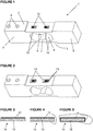
- Figure 1 shows a dual-beam cantilever load cell 1 with a top side 2 and a bottom side 3 (not visible), a load-receiving end portion 4 and a mounting end portion 5, an upper bending beam portion 6 and a lower bending beam portion 7.
- the load-receiving end portion 4 has two threaded holes 8 from the top side 2 for the attachment of a weighing platform or other kind of load receiver.
- the mounting end portion 5, analogously, has two threaded holes from the bottom (not visible in the drawing) to mount the load cell 1 on the base plate of a weighing scale (not shown) or on any other kind of supporting understructure.
- the bending beam portions 6, 7 are formed by machining an appropriately contoured opening 9 through the center of the load cell 1.
- the opening 9 is shaped to form thin bridge portions 10 in the bending beam portions 6, 7.
- Four strain gauges 12 - two on the top bending beam portion 6 and two (not visible) on the lower bending beam portion 7 are mounted with their resistor tracks exactly aligned and centered over the thin bridge portions 10.
- the principles of wiring the four strain gauges 12 in a Wheatstone bridge circuit and obtaining an electrical signal representative of a weighing load applied to the load-receiving end portion 4 of a dual-beam cantilever load cell 1 are well known in the art (see for example US 5,052,505 ) and will therefore not be further described here.
- FIG. 2 shows the same load cell 1 after moisture-insulating polymer film covers 14 have been installed on top of the strain gauges 12 by means of a commercially available strain gauge adhesive, for example M-Bond 43B made by Vishay Precision Group, Micro-Measurements, 951 Wendell Blvd., Wendell, NC 27591, USA.
- the area covered by moisture-insulating polymer film 14 extends somewhat beyond the borders of each strain gauge 12.
- the electrode pads 13 are left partially uncovered, so that circuit wires can be soldered or welded to them.
- the load cell in Figures 1 and 2 could also be replaced by a rocker pin load cell or any object on which strain measurements are to be performed, for example pressure sensors, or landing gears of airplanes or the chassis frames of trucks, as well as machines for static and dynamic testing and building structures.
- the base material for the moisture-insulating polymer film 14 is a thin sheet of polymer material 15.
- the polymer sheet material 15 receives its moisture-insulating property from a moisture barrier coating 17 of inorganic material, which is applied to the polymer sheet material 15 in a deposition process.
- the inorganic moisture barrier coating 17 can be applied to one side of the polymer sheet material 15 ( Figure 3 ), to both sides ( Figure 4 ), or to both sides as well as to the very narrow surface strips around the border ( Figure 5 ), so that the polymer material 15 is encapsulated by the moisture barrier coating 17.
- the thickness of the moisture-insulating polymer film 14 for a low-capacity dual-cantilever load cell 1 is within the range of micrometers.
- a greater thickness is feasible for load cells of higher weighing capacity, for example shear beam load cells and column load cells.
- Moisture-insulating polymer films 14 as thick as, for example 500 ⁇ m (micrometers) appear feasible for such high-capacity load cells and are considered to lie within the scope of this invention.
- Polymers that are suitable for the basic polymer sheet material 15 include for example PET (polyethylene terephthalate), polyimide, PEEK (polyether ether ketone) and related materials such as KAPTON (a polyimide film developed by DuPont).
- Non-metallic inorganic materials that are suitable for the moisture barrier coating 17 used in the method according to the invention include for example SiO 2 , Al 2 O 3 , TiO and SiN. Also possible are inorganic-organic multi-layered structures.
- the typical thickness of the moisture barrier coating 17 is less than 200 nanometers, but can go up to 2000 nanometers, depending on the manufacturing process used.
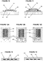
- strain gauges there are two commercially available types of strain gauges.
- the metallic resistor track 22 in the form of a meandering structure ending in electrode pads 23 and backed by a polymer substrate foil 20 is exposed on top, i.e. the open-faced strain gauge 21A has no mechanical protection cover.
- the resistor track 22 is protected by a mechanical protection cover 26, for example a polyimide layer.
- the method according to the present invention is applicable to open-faced strain gauges 21A as well as protected strain gauges 25A.
- Figure 7B and Figure 9B are showing the same layer structures of the strain gauge 21A and strain gauge 25A with the difference that on the surface of the polymer substrate foil 20 a moisture barrier coating 17 has been applied prior to the arrangement of a resistor track in the shape of a meandering structure and the electrode pads.
- the step of applying the moisture-insulating polymer film to the strain gauge can be implemented in different ways, as exemplified by (but not limited to) the following detail procedures 1, 2, and 3:
- the moisture-insulating polymer film 34 has a one-sided moisture barrier coating (as in Figure 3 ), the moisture-insulating polymer film 34 is installed with the coated side facing outward. An inward facing coated side is also possible and shall fall under the scope of the invention, but is less effective.
- the electrode pads 43 of the strain gauge are left at least partially uncovered by the moisture-insulating polymer film so that circuit wires can be soldered or welded to them.
- the strain gauges 31, 35 and the moisture-insulating polymer films 34 are fixated on the load cell body 33 by clamping, and the load cell is placed into an oven where the adhesive bonds 38 of the strain gauges 31, 35 and the moisture-insulating polymer films 34 are heat-cured together.
- the moisture-insulating polymer film 34 is installed on strain gauges 31, 35 that have already been heat-cured and are permanently bonded to a load cell body 33.
- the moisture-insulating polymer film 34 is laid over an area including the strain gauge 31, 35 and an adjoining border area 37 of the surface of the load cell body 33, using for example the previously mentioned M-Bond 43B.
- Moisture-insulating polymer film 14 with one-sided moisture barrier coating 17 is installed with the coated side facing outward.
- the electrode pads 43 of the strain gauge 31, 35 are at least partially outside the moisture-insulating polymer film 34 so that circuit wires can be soldered or welded to them.
- the load cell is placed in an oven to heat-cure the adhesive bond 38 of the moisture-insulating polymer film 34.
- the moisture-insulating polymer film 34 can also be installed with a room-temperature-curing adhesive, in which case the adhesive bond of the moisture-insulating polymer film 34 solidifies within a specified time period without oven-curing.
- the moisture-insulating polymer film 14, 34, 44 provides a high degree of protection, as no moisture can traverse the moisture barrier coating 17 of the polymer film 15. Lateral penetration of moisture through the adhesive layer between the moisture-insulating polymer film 14, 34, 44 and the surface of the load cell body 33 is minimized, as the exposed border of the adhesive layer is only 2 to 5 ⁇ m (micrometers) thick and the travel distance for the moisture molecules from the exposed border to the resistor tracks 22 of the strain gauge 31, 35 is relatively long.
- the moisture-insulating polymer film 14, 34, 44 is installed during the manufacturing process of strain gauges, so that the resultant product is a moisture-insulated strain gauge.
- the installation of the moisture-insulating polymer film 14, 34, 44 can be performed on individual strain gauges or on multi-unit sheets that are subsequently cut up into individual strain gauges. Strain gauges are normally produced in the form of multi-unit sheets, which are subsequently cut up into the final form of individual strain gauges that represent the final product.
- Figure 12A shows a top view of a strain gauge 41, 45 ( Figures 13 and 14 ) on which a moisture-insulating polymer film 44 has been installed according to the method of the invention.
- the strain gauge of Figure 12A can be an open-faced strain gauge 21A, 41 (as shown in cross-section in Figure 7A and 13 ) without a mechanical protection cover over the resistor tracks 42, or it can be an protected strain gauge 25A, 45 (as shown in cross-section in Figure 9A and 14 ) with a mechanical protection cover 26, 46 between the resistor tracks 42 and the moisture-insulating polymer film 44.
- the uncovered surface of the strain gauge can be overlaid by additional metallic material 48 (see Figure 12B ) that remains on the strain gauge after the chemical etching like the resistor track and the electrode pads 43.
- additional metallic material 48 see Figure 12B
- a small gap ensures that no electrically conductive connection exists between the additional metallic material 48 and the resistor track 42 or the electrode pads 43.
- the entire strain gauge 12, 21A, 21B, 25A, 25B, 31, 35, 41, 45 can be overlaid with the moisture-insulating polymer film 14, 34, 44.
- an opening 47 is made through the moisture-insulating polymer film 14, 34, 44 to the electrode pads 13, 23, 43 (see Figure 12C ) to ensure that circuit wires can be soldered or welded to them.
- the strain gauge of Figure 12C can also be a moisture-insulated open-faced strain gauge 21B as shown in Figure 7B without a mechanical protection cover over the resistor tracks 42, or it can be a moisture-insulated protected strain gauge 25B as shown in Figure 9B .
- the inventive method of manufacturing a strain gauge which is insulated against moisture penetration is not limited to the moisture protection of strain gauges in load cells that are used in weighing, but can be used generally for strain gauges that need protection against moisture without the drawback of compromising the measurement accuracy as a result of the protective measures.
- This includes for example strain gauges used in pressure sensors, or strain gauges used in the landing gears of airplanes or built into the chassis frames of trucks, as well as strain gauges used for static and dynamic testing of machines and building structures.
- Such applications and variations of the concepts described and claimed herein are considered to fall within the scope of protection that is hereby sought for the present invention.
Landscapes
- Physics & Mathematics (AREA)
- General Physics & Mathematics (AREA)
- Measurement Of Force In General (AREA)
Priority Applications (9)
| Application Number | Priority Date | Filing Date | Title |
|---|---|---|---|
| EP18191935.8A EP3617683A1 (en) | 2018-08-31 | 2018-08-31 | Method of insulating a strain gauge against moisture penetration |
| JP2021510965A JP2021535390A (ja) | 2018-08-31 | 2019-08-30 | 湿気絶縁ひずみゲージ、および湿気の侵入に対してひずみゲージを絶縁する方法 |
| PCT/EP2019/073246 WO2020043892A2 (en) | 2018-08-31 | 2019-08-30 | Moisture-insulated strain gauge and method of insulating a strain gauge against moisture penetration |
| US17/269,910 US11841282B2 (en) | 2018-08-31 | 2019-08-30 | Strain gauge insulated against moisture penetration and method of manufacturing same |
| CN201980056764.3A CN112912704A (zh) | 2018-08-31 | 2019-08-30 | 湿气隔绝型应变片及为应变片隔绝湿气渗透的方法 |
| KR1020217008842A KR20210049144A (ko) | 2018-08-31 | 2019-08-30 | 습기 차단된 스트레인 게이지 및 스트레인 게이지의 습기 침투 차단 방법 |
| EP19759004.5A EP3844467A2 (en) | 2018-08-31 | 2019-08-30 | Moisture-insulated strain gauge and method of insulating a strain gauge against moisture penetration |
| IL280992A IL280992A (en) | 2018-08-31 | 2021-02-21 | Moisture-insulated voltmeter and method of insulating a voltmeter against moisture penetration |
| JP2024001731A JP2024038304A (ja) | 2018-08-31 | 2024-01-10 | 湿気絶縁ひずみゲージ、および湿気の侵入に対してひずみゲージを絶縁する方法 |
Applications Claiming Priority (1)
| Application Number | Priority Date | Filing Date | Title |
|---|---|---|---|
| EP18191935.8A EP3617683A1 (en) | 2018-08-31 | 2018-08-31 | Method of insulating a strain gauge against moisture penetration |
Publications (1)
| Publication Number | Publication Date |
|---|---|
| EP3617683A1 true EP3617683A1 (en) | 2020-03-04 |
Family
ID=63452514
Family Applications (2)
| Application Number | Title | Priority Date | Filing Date |
|---|---|---|---|
| EP18191935.8A Withdrawn EP3617683A1 (en) | 2018-08-31 | 2018-08-31 | Method of insulating a strain gauge against moisture penetration |
| EP19759004.5A Pending EP3844467A2 (en) | 2018-08-31 | 2019-08-30 | Moisture-insulated strain gauge and method of insulating a strain gauge against moisture penetration |
Family Applications After (1)
| Application Number | Title | Priority Date | Filing Date |
|---|---|---|---|
| EP19759004.5A Pending EP3844467A2 (en) | 2018-08-31 | 2019-08-30 | Moisture-insulated strain gauge and method of insulating a strain gauge against moisture penetration |
Country Status (7)
| Country | Link |
|---|---|
| US (1) | US11841282B2 (ja) |
| EP (2) | EP3617683A1 (ja) |
| JP (2) | JP2021535390A (ja) |
| KR (1) | KR20210049144A (ja) |
| CN (1) | CN112912704A (ja) |
| IL (1) | IL280992A (ja) |
| WO (1) | WO2020043892A2 (ja) |
Families Citing this family (2)
| Publication number | Priority date | Publication date | Assignee | Title |
|---|---|---|---|---|
| US11698309B2 (en) * | 2020-03-05 | 2023-07-11 | Delta Electronics, Inc. | Linear actuator |
| CN115235331A (zh) * | 2020-12-31 | 2022-10-25 | 厦门市诺盛测控技术有限公司 | 一种焊点镀膜的应变计制备模版 |
Citations (7)
| Publication number | Priority date | Publication date | Assignee | Title |
|---|---|---|---|---|
| US4557150A (en) | 1982-10-26 | 1985-12-10 | Kabushiki Kaisha Ishida Koki Seisakusho | Load cell |
| US4957177A (en) | 1989-08-09 | 1990-09-18 | Toledo Scale Corporation | Enclosed moment-insensitive load cell |
| US5052505A (en) | 1989-05-24 | 1991-10-01 | Ishida Scales Mfg. Co., Ltd. | Load cell |
| EP0667514A2 (de) * | 1994-02-15 | 1995-08-16 | Hottinger Baldwin Messtechnik Gmbh | Verfahren zur Herstellung eines Dehnungsmessstreifens |
| DE29922560U1 (de) * | 1999-12-22 | 2000-03-16 | Fraunhofer Ges Forschung | Vorrichtung zur flächigen Messung von Betriebszustandsgrößen bei Maschinenkomponenten |
| EP1560011A1 (de) | 2004-01-27 | 2005-08-03 | Mettler-Toledo GmbH | Dehnmessstreifen mit Feuchtigkeitsschutz durch inhomogene anorganische Schicht auf glättender Polymerschicht (ORMOCER) und Schlitzanordnung |
| EP3358292A1 (en) * | 2015-09-29 | 2018-08-08 | Minebea Mitsumi Inc. | Strain gauge, load sensor, and method for manufacturing strain gauge |
Family Cites Families (16)
| Publication number | Priority date | Publication date | Assignee | Title |
|---|---|---|---|---|
| US3599139A (en) * | 1969-03-14 | 1971-08-10 | Blh Electronics | Strain gage protective cover |
| US4015326A (en) * | 1975-02-18 | 1977-04-05 | Brewer Engineering Laboratories, Inc. | Method of mounting a strain gage to a surface |
| DE2728916A1 (de) * | 1977-06-27 | 1979-01-18 | Hottinger Messtechnik Baldwin | Verfahren und vorrichtung zum abdecken eines dehnungsmesstreifens |
| JPS5920088B2 (ja) * | 1978-08-24 | 1984-05-10 | 東芝テック株式会社 | ロ−ドセル |
| JPS5542156U (ja) * | 1978-09-14 | 1980-03-18 | ||
| JPS5953147B2 (ja) | 1978-09-20 | 1984-12-24 | 三菱電機株式会社 | 水平固定管の全姿勢円周溶接方法 |
| JPH0528947U (ja) | 1992-09-22 | 1993-04-16 | 大和製衡株式会社 | ロードセル |
| DE4236985C1 (de) * | 1992-11-04 | 1994-02-24 | Hottinger Messtechnik Baldwin | Dehnungsmeßstreifen |
| JP3487675B2 (ja) * | 1995-06-16 | 2004-01-19 | 松下電器産業株式会社 | 力学量センサの製造方法 |
| JP2001091205A (ja) | 1999-07-22 | 2001-04-06 | Sumitomo Metal Ind Ltd | 物体搭載装置 |
| EP1384980A1 (de) * | 2002-07-25 | 2004-01-28 | Mettler-Toledo GmbH | Feuchtigkeitsschutz für einen elektromechanischen Wandler |
| ATE441843T1 (de) * | 2004-01-27 | 2009-09-15 | Mettler Toledo Ag | Kraftmesszelle mit dehnmessstreifen mit klebeschicht aus anorganisch-organischem hybrid- polymer (ormocer) |
| US7461560B2 (en) * | 2005-03-28 | 2008-12-09 | Microstrain, Inc. | Strain gauge with moisture barrier and self-testing circuit |
| JP2010243192A (ja) | 2009-04-01 | 2010-10-28 | A & D Co Ltd | 歪ゲージとロードセル。 |
| US20170213648A1 (en) | 2014-08-01 | 2017-07-27 | Western Michigan University Research Foundation | Self-supported electronic devices |
| US10359325B2 (en) * | 2017-05-15 | 2019-07-23 | Strain Measurement Devices, Inc. | Thin film strain gauge |
-
2018
- 2018-08-31 EP EP18191935.8A patent/EP3617683A1/en not_active Withdrawn
-
2019
- 2019-08-30 EP EP19759004.5A patent/EP3844467A2/en active Pending
- 2019-08-30 US US17/269,910 patent/US11841282B2/en active Active
- 2019-08-30 JP JP2021510965A patent/JP2021535390A/ja active Pending
- 2019-08-30 CN CN201980056764.3A patent/CN112912704A/zh active Pending
- 2019-08-30 KR KR1020217008842A patent/KR20210049144A/ko not_active Application Discontinuation
- 2019-08-30 WO PCT/EP2019/073246 patent/WO2020043892A2/en unknown
-
2021
- 2021-02-21 IL IL280992A patent/IL280992A/en unknown
-
2024
- 2024-01-10 JP JP2024001731A patent/JP2024038304A/ja active Pending
Patent Citations (8)
| Publication number | Priority date | Publication date | Assignee | Title |
|---|---|---|---|---|
| US4557150A (en) | 1982-10-26 | 1985-12-10 | Kabushiki Kaisha Ishida Koki Seisakusho | Load cell |
| US5052505A (en) | 1989-05-24 | 1991-10-01 | Ishida Scales Mfg. Co., Ltd. | Load cell |
| US4957177A (en) | 1989-08-09 | 1990-09-18 | Toledo Scale Corporation | Enclosed moment-insensitive load cell |
| EP0667514A2 (de) * | 1994-02-15 | 1995-08-16 | Hottinger Baldwin Messtechnik Gmbh | Verfahren zur Herstellung eines Dehnungsmessstreifens |
| US5631622A (en) | 1994-02-15 | 1997-05-20 | Hottinger Baldwin Messtechnik Gmbh | Strain gage and measuring transducer and method of producing the same |
| DE29922560U1 (de) * | 1999-12-22 | 2000-03-16 | Fraunhofer Ges Forschung | Vorrichtung zur flächigen Messung von Betriebszustandsgrößen bei Maschinenkomponenten |
| EP1560011A1 (de) | 2004-01-27 | 2005-08-03 | Mettler-Toledo GmbH | Dehnmessstreifen mit Feuchtigkeitsschutz durch inhomogene anorganische Schicht auf glättender Polymerschicht (ORMOCER) und Schlitzanordnung |
| EP3358292A1 (en) * | 2015-09-29 | 2018-08-08 | Minebea Mitsumi Inc. | Strain gauge, load sensor, and method for manufacturing strain gauge |
Non-Patent Citations (1)
| Title |
|---|
| "OIML R 60 - Parts 1 and 2, Metrological Regulation for Load Cells", OIML (ORGANISATION INTERNATIONALE DE METROLOGIE LEGALE, PARIS, FRANCE |
Also Published As
| Publication number | Publication date |
|---|---|
| US20210262873A1 (en) | 2021-08-26 |
| US11841282B2 (en) | 2023-12-12 |
| WO2020043892A2 (en) | 2020-03-05 |
| WO2020043892A3 (en) | 2020-04-16 |
| IL280992A (en) | 2021-04-29 |
| KR20210049144A (ko) | 2021-05-04 |
| JP2021535390A (ja) | 2021-12-16 |
| CN112912704A (zh) | 2021-06-04 |
| EP3844467A2 (en) | 2021-07-07 |
| JP2024038304A (ja) | 2024-03-19 |
Similar Documents
| Publication | Publication Date | Title |
|---|---|---|
| US7197940B2 (en) | Moisture protection for an electromechanical transducer | |
| JP2024038304A (ja) | 湿気絶縁ひずみゲージ、および湿気の侵入に対してひずみゲージを絶縁する方法 | |
| US4343197A (en) | Load-cell balance | |
| US7215870B2 (en) | Moisture protection for an electromechanical transducer | |
| RU2171455C2 (ru) | Емкостный датчик давления и способ его изготовления | |
| US7243558B2 (en) | Bonding of strain gauges to the deformable body of a force-measuring cell | |
| US4064744A (en) | Strain sensorextensiometer | |
| RU2398195C1 (ru) | Способ изготовления нано- и микроэлектромеханической системы датчика давления и датчик давления на его основе | |
| AU753160B2 (en) | Load cell | |
| GB2369889A (en) | Strain sensing device | |
| CA1239806A (en) | Capacitive sensing cell made of brittle material | |
| US4464419A (en) | Process for a low back-action, quasi-hermetic covering of susceptible physical structures | |
| JPH08122359A (ja) | 半導体加速度センサとその製造方法および試験方法 | |
| JP2549815B2 (ja) | 半導体加速度センサおよびその試験方法 | |
| CN110873616A (zh) | 防潮应变片及其制备方法 | |
| CN114414123A (zh) | 一种异形金属基底上的应变传感器芯片及其原位制备方法 | |
| US20210190606A1 (en) | Strain gages and methods for manufacturing thereof | |
| RU2397460C1 (ru) | Датчик давления на основе тензорезисторной тонкопленочной нано- и микроэлектромеханической системы | |
| Schmaljohann et al. | Thin film sensors for measuring small forces | |
| EP3939783B1 (en) | Insulating film-equipped metal material and pressure sensor | |
| WO2021126261A1 (en) | Strain gages and methods for manufacturing thereof | |
| CN109690233A (zh) | 应变片以及用于制造应变片的方法 | |
| US6301775B1 (en) | Alumina encapsulated strain gage, not mechanically attached to the substrate, used to temperature compensate an active high temperature gage in a half-bridge configuration | |
| JPH1138038A (ja) | 加速度センサ | |
| JP2009085672A (ja) | 剪断力検出装置 |
Legal Events
| Date | Code | Title | Description |
|---|---|---|---|
| PUAI | Public reference made under article 153(3) epc to a published international application that has entered the european phase |
Free format text: ORIGINAL CODE: 0009012 |
|
| AK | Designated contracting states |
Kind code of ref document: A1 Designated state(s): AL AT BE BG CH CY CZ DE DK EE ES FI FR GB GR HR HU IE IS IT LI LT LU LV MC MK MT NL NO PL PT RO RS SE SI SK SM TR |
|
| AX | Request for extension of the european patent |
Extension state: BA ME |
|
| STAA | Information on the status of an ep patent application or granted ep patent |
Free format text: STATUS: THE APPLICATION IS DEEMED TO BE WITHDRAWN |
|
| RAP1 | Party data changed (applicant data changed or rights of an application transferred) |
Owner name: METTLER-TOLEDO (CHANGZHOU) PRECISION INSTRUMENTS CO., LTD Owner name: METTLER-TOLEDO INTERNATIONAL TRADING (SHANGHAI) CO. LTD. Owner name: METTLER-TOLEDO (CHANGZHOU) MEASUREMENT TECHNOLOGY CO., LTD |
|
| 18D | Application deemed to be withdrawn |
Effective date: 20200905 |